A Framework for Integrating ESL Tools - IRIT
A Framework for Integrating ESL Tools - IRIT
A Framework for Integrating ESL Tools - IRIT

You also want an ePaper? Increase the reach of your titles
YUMPU automatically turns print PDFs into web optimized ePapers that Google loves.
First Workshop on Process-based approaches<br />
<strong>for</strong> Model-Driven Engineering (PMDE)<br />
June 7, 2011<br />
Birmingham, UK<br />
Proceedings<br />
In conjunction with<br />
ECMFA 2011 conference,<br />
June 6-9, 2011, Birmingham, UK
Contents<br />
Preface<br />
Foreword……………………………………………………………………………………. v<br />
Organization……………………………………………………………………………….. vi<br />
Collaborative Processes in the Real World: Embracing their Essential Nature<br />
Komlan Akpédjé KEDJI, Bernard COULETTE, Mahmoud NASSAR………………………….. 1<br />
<strong>Framework</strong> <strong>for</strong> <strong>Integrating</strong> <strong>ESL</strong> <strong>Tools</strong><br />
Ali Koudri, Teodora Petrisor, Joel Champeau, and Vincent Leilde…………………..……….. 13<br />
A Domain Specific Model to Support Model Driven Development of Business Logic<br />
Tobias Brückmann, Volker Gruhn………………………………………………………………….. 23<br />
Towards an Enactment Mechanism <strong>for</strong> MODAL Process Models<br />
Pierre-Yves Pillain, Joel Champeau, Hanh Nhi Tran………………………………….............. 33<br />
Component-oriented Multi-metamodel Process Modeling <strong>Framework</strong> (CoMProM)<br />
Fahad R. Golra and Fabien Dagnat………………………………………………………….......... 44
Foreword<br />
Welcome to the first edition of the Process-centered approaches <strong>for</strong> Model-Driven<br />
Engineering (PMDE), held in Birmingham, UK, on June 7 th , 2011.<br />
The PMDE Workshop aims to gather researchers and industrial practitioners<br />
working in the field of Model- Based Engineering, and more particularly on the<br />
use of processes to improve software reliability and productivity. Indeed, despite<br />
the benefits brought by the Model-Driven Engineering approach, the complexity<br />
of today's applications is still hard to master. Building complex and trustworthy<br />
software systems in the shortest time-to- market remains the challenging objective<br />
that competitive companies are facing constantly. A more challenging objective<br />
<strong>for</strong> these companies is to be able to <strong>for</strong>malize their development processes in<br />
order to analyze them, to simulate and execute them, and to reason about their<br />
possible improvement.<br />
The PMDE workshop’s goal in this edition is to present research results or workin-progress<br />
in all areas of process-based approaches <strong>for</strong> model-driven engineering.<br />
The main topics that where targeted this year by accepted papers range from<br />
collaborative processes, process enactment, DSLs to support MDE development,<br />
to the proposition of new process modeling techniques and frameworks.<br />
The organization of this first edition of the PMDE workshop would not have been<br />
possible without the dedication and professional work of many colleagues. We<br />
wish to express our gratitude to all contributors who submitted papers. Their work<br />
<strong>for</strong>med the basis <strong>for</strong> the success of this year’s edition and we hope, <strong>for</strong> the<br />
upcoming editions of PMDE. We would also like to thank the Program<br />
Committee members and reviewers <strong>for</strong> volunteering their time to help assess the<br />
submissions and guarantee the quality of the workshop.<br />
Finally, we are also grateful to the ECMFA 2011 organizing Committee,<br />
particularly to Behzad Bordbar and Rami Bahsoon <strong>for</strong> their help and valuable<br />
advices.<br />
June, 2011, The Organizing Committee.<br />
Reda Bendraou<br />
Redouane Lbath<br />
Marie-Pierre Gervais<br />
Bernard Coulette
Organization<br />
Program committee<br />
Colin Atkinson (University of Mannheim, Mannheim, Germany)<br />
Behzad Bordbar (University of Birmingham, UK)<br />
Jacky Estublier (University of Grenoble, France)<br />
Christian Haerdt (EADS, Germany)<br />
Jason Xabier Mansell (TECNALIA - ICT/European Software Institute, Spain)<br />
Larrucea Uriarte Xabier (TECNALIA - ICT/European Software Institute, Spain)<br />
Leon J. Osterweil (University of Massachusetts, USA)<br />
Richard Paige (University of York, UK)<br />
Garousi Vahid (University of Calgary Alberta, Canada)<br />
Organizers<br />
Bendraou Reda (LIP6, France)<br />
Lbath Redouane (<strong>IRIT</strong>, France)<br />
Coulette Bernard (<strong>IRIT</strong>, France)<br />
Gervais Marie-Pierre (LIP6, France)
Collaborative Processes in the Real World:<br />
Embracing their Ad-hoc Nature<br />
Komlan Akpédjé KEDJI 1 , Bernard COULETTE 1 , Mahmoud NASSAR 2 ,<br />
Redouane LBATH 1 , and Minh Tu TON THAT 3<br />
1 <strong>IRIT</strong>, Toulouse, France,<br />
{kedji, bernard.coulette, redouane.lbath}@irit.fr<br />
2 ENSIAS, SIME, Rabat, Morocco nassar@ensias.ma<br />
3 University of Toulouse, France minhtutonthat@gmail.com<br />
Abstract. In real world projects, collaboration in not only omnipresent,<br />
but efficient collaborative processes are also hard to get right, especially<br />
when the cohesion needed is high. In software engineering, a sizable<br />
amount of in<strong>for</strong>mation needed to understand and support collaboration<br />
is unavailable be<strong>for</strong>e the start of the project. We argue that such lack of<br />
in<strong>for</strong>mation is essential to the field, and needs to be embraced, rather<br />
that fought, or worse, ignored. We believe collaboration in the real world<br />
to be a feed-back process, where short-term decisions guide collaboration,<br />
and where the way collaboration unfolds in the project, in turn, guides<br />
future decisions about collaboration. Practitioners should be given the<br />
ability to express such evolving understanding about collaboration in a<br />
<strong>for</strong>malism suited <strong>for</strong> easy representation and tool-provided assistance.<br />
To this end, we propose an extension to the Software & System Process<br />
Engineering Meta-Model (SPEM), which introduces concepts needed to<br />
represent precise and dynamic collaboration setups that practitioners<br />
create to address ever-changing challenges.<br />
Keywords: process design; process planning; collaboration; collaborative<br />
work<br />
1 Introduction<br />
Collaboration can be simply defined as the act of working together, towards a<br />
common goal, and is a pervasive concern in any collective endeavor. While process<br />
<strong>for</strong>malisms and standards like SPEM [11] exist, support <strong>for</strong> the description<br />
of ad-hoc collaboration (that is, collaboration that is done because it happens<br />
to be needed, and not because it was planned) is lacking. We show that in the<br />
field of computer engineering, collaboration is usually ad-hoc, and that this is<br />
not by accident, but rather by necessity. We embrace that necessity in our quest<br />
to build a better mental model of collaboration, so as to be able to offer effective<br />
tool support to practitioners. Our approach naturally results in a feedback loop<br />
between reality and the model, where decisions taken in the project are continuously<br />
injected in the model, and at any given moment, the state of the model<br />
guides future decisions.<br />
1
We take the MDE (Model-Driven Engineering) approach, and build a metamodel<br />
suited to the description of ad-hoc collaboration practices, which extends<br />
SPEM. This paper shows, on an example taken from a real world project, how<br />
appropriate our conceptualization is <strong>for</strong> actual software projects. It should be<br />
noted that our ef<strong>for</strong>t is not restricted to face to face or synchronous interactions,<br />
but covers any collective work that escapes the plan-and-execute scheme.<br />
The rest of this paper is organized as follows. Section 2 characterizes adhoc<br />
collaboration to build an understanding which we <strong>for</strong>malize in Section 3<br />
as a metamodel. Section 4 describes and represents a real world collaboration<br />
scenario with the proposed concepts. Section 5 summarizes some related works.<br />
2 Ad-hoc Collaborative Processes<br />
Collaboration happens whenever two or more individuals work on the same<br />
task or interact with the same work product. Collaboration has been defined<br />
as “a collective ef<strong>for</strong>t to construct a shared understanding of a problem and its<br />
solution” [16].<br />
Various concerns such as power sharing, responsibility assignment, appropriate<br />
recognition, giving credit, coordinating actions, trust, etc., can easily undermine<br />
collaborative ef<strong>for</strong>ts, by incurring to much cognitive overhead on participants,<br />
and taking the focus away from their actual tasks. In software engineering,<br />
these problems are further complicated by worldwide distribution of teams, the<br />
amount of knowledge sharing required, communication among people with different<br />
expertise, and high complexity and interdependency of artifacts [9].<br />
Thus, people usually collaborate only when the need arises. While there<br />
can be some prior planning, collaboration, especially in software engineering,<br />
is mostly ad-hoc [3, 15]. Whereas planned collaboration happens because it was<br />
on the agenda, ad-hoc collaboration is prompted by a new issue or new considerations<br />
in an existing issue. A field study found ad-hoc collaboration to amount<br />
to as much as 69% of all collaborative work in software development [15].<br />
Any tool that seeks to support collaboration had better speak the language<br />
of its users, so as to not increase the cognitive overhead they are already fighting<br />
with, and provide a frictionless surface <strong>for</strong> development [2]. When ad-hoc<br />
collaboration occurs in software engineering, the concepts involved <strong>for</strong> the practitioners<br />
are the actual people doing the job, what each of them is doing, and<br />
which artifacts they are manipulating.<br />
However, the central concepts used in process models like SPEM (role, product,<br />
task) are at a much higher level of abstraction than those used by practitioners<br />
to understand collaboration, thus hiding needed in<strong>for</strong>mation:<br />
– Role. How do we describe interactions between people playing the same role,<br />
but still doing different things like coding two dependant components, when<br />
the very need <strong>for</strong> two people surfaces only in the middle of the project?<br />
– Tasks. When we find out that more than one person is needed <strong>for</strong> a task<br />
(which is the very definition of collaboration), how can we, <strong>for</strong> example,<br />
2
specify work dependency, when we lack a concept to represent work done by<br />
a specific person in the context of a task?<br />
– Products. When a group of participants have each a copy of a work product<br />
in their workspace, how do we describe their agreement <strong>for</strong> merging changes<br />
to produce an official version of the work product, while lacking the ability<br />
to identify each of those copies?<br />
SPEM is glaringly silent on such issues, and even proposes that these issues<br />
be solved by project manager as they see fit, when instantiating process models<br />
4 . We need to frame collaboration in terms of more appropriate concepts to<br />
effectively support the kind of ad-hoc collaboration that is dominant in software<br />
engineering.<br />
If we focus on ad-hoc collaboration, and structure it with the concepts familiar<br />
to practitioners, it follows that we can’t always describe collaboration in<br />
a generic way, and just reuse that description <strong>for</strong> any project. But this is not<br />
a limitation, as collaboration practices are ad-hoc precisely because in<strong>for</strong>mation<br />
needed is not available earlier. Postponing the description of ad-hoc collaboration<br />
is there<strong>for</strong>e better suited to taking into account whatever creative collaboration<br />
setup practitioners create to answer their actual needs [6].<br />
3 The CM_SPEM Metamodel<br />
Our conceptualization is presented as a metamodel, CM_SPEM (Collaborative<br />
Model-based Software & Systems Process Engineering Metamodel 5 ), that extends<br />
SPEM [11] but adding packages. Due to space limitation, the metamodel<br />
described in this article focuses on the structural description of collaboration,<br />
and the OCL (Object Constraint Language) [13] rules which specify the static<br />
semantics of the metamodel as well-<strong>for</strong>medness rules have also been left out. A<br />
more detailed overview is available in [4].<br />
In the current work, we chose to describe collaboration using the same central<br />
concepts which structure ad-hoc collaboration: Actor, ActorSpecificTask, and<br />
ActorSpecificArtifact. These concepts can be seen as refinements of the concepts<br />
we borrow from SPEM: RoleUse (from SPEM::ProcessStructure), TaskUse (from<br />
SPEM::ProcessWithMethods), and WorkProductUse (from SPEM::ProcessStructure).<br />
We encode knowledge about collaboration setups as relationships between<br />
the previous concepts, and use the SPEM Kind mechanism to allow them<br />
to have user-defined qualifications. This helps avoid the temptation to provide<br />
a fixed set of relationships which cannot cover all collaboration setups, while<br />
still providing some general structure. These structural concepts are grouped in<br />
the CM_SPEM::CollaborationStructure package, which reuses SPEM::Process-<br />
Structure and SPEM::ProcessWithMethods.<br />
4 See Section 16 “Enacting SPEM 2.0 Processes” of the standard [11].<br />
5 This work is part of a project which focuses on the MDE (Model Driven Engineering)<br />
approach to software development, hence the name of the metamodel. However, this<br />
paper is restricted to the collaborative features of the metamodel.<br />
3
Fig. 1: Overview of the Collaboration Structure package. Concepts in blue are<br />
borrowed from SPEM.<br />
4
3.1 Central Concepts<br />
The three central concepts in CM_SPEM are Actor, ActorSpecificTask, and ActorSpecificArtifact.<br />
All of them extend ExtensibleElement (from SPEM::Core).<br />
An actor identifies a specific human participant in a project. It is linked to<br />
instances of RoleUse (SPEM::ProcessStructure) to specify that the actor plays<br />
the corresponding roles. An ActorSpecificTask is a unit of work done by a specific<br />
actor, towards the execution of a TaskUse. An ActorSpecificArtifact 6 is a<br />
physical occurrence of a WorkProductUse, in the personal workspace of a specific<br />
actor. This is the personal copy of the actor, and is manipulated only by<br />
him/her 7 .<br />
3.2 Relationships<br />
All the defined relationships are subclasses of SPEM::Core::ExtensibleElement<br />
(which allow them to have user-defined qualifications) and SPEM::Core::BreakdownElement<br />
(which allows them to be nested by SPEM containers like Activity).<br />
A first set of relationships is used to associate instances of different concepts:<br />
TaskAssignment links an Actor to an ActorSpecificTask assigned to him/her, ArtifactOwnership<br />
relates an Actor to an ActorSpecificArtifact in his/her workspace,<br />
ArtifactUse relates an ActorSpecificTask to an ActorSpecificArtifact manipulated<br />
when carrying it out. This set of relationships can be conceived as a mirror<br />
of the set of links defined in SPEM between RoleUse and Activity (ProcessPer<strong>for</strong>mer),<br />
RoleUse and WorkProductUse (ProcessResponsibilityAssignment), and,<br />
Activity and WorkProductUse (ProcessParameter) 8 .<br />
The second set of relationships is used to relate instances of the same concept:<br />
– ActorRelationship, which is used to describe a couple of actors. An Actor-<br />
Relationship can be used to state that an actor A reports to actor B in a<br />
certain task, so that all contributions made by A, in the context of that task,<br />
are by default sent to B.<br />
– ActorSpecificTaskRelationship, which is used to describe a couple of ActorSpecificTask.<br />
An ActorSpecificTaskRelationship can <strong>for</strong> example specify<br />
temporal dependencies between the works done by two different actors in<br />
the context of the same TaskUse.<br />
6 In SPEM, Artifact (a tangible work product) is one of the three work product kinds.<br />
The two other are Outcome (a non-tangible work product) and Deliverable (a group<br />
of artifacts). While “Artifact” in ActorSpecificArtifact has a wider semantic (anything<br />
that represents a WorkProduct), the similarity with “Artifact” as used in<br />
SPEM is defensible. Indeed, an Outcome usually does not have distinct representations<br />
<strong>for</strong> each participant, and a Deliverable can be considered as a special Artifact.<br />
7 Arguably, there could be a lot of such copies, <strong>for</strong> the same actor, in different version<br />
control branches <strong>for</strong> example. However, we are only interested in the fact that any<br />
one of these artifacts is only manipulated by a single actor<br />
8 See Figure 9.4 of SPEM 2.0 [11]<br />
5
– ActorSpecificArtifactRelationship, which is used to describe a couple of ActorSpecificArtifact.<br />
An ActorSpecificArtifactRelationship can <strong>for</strong> example<br />
specify that an artifact A is the reference version of an artifact B (A and B<br />
represent the same work product).<br />
4 Ad-hoc Collaboration in a Real World Project<br />
This section describes an ad-hoc collaboration scenario extracted from a real<br />
world project, using the concepts introduced in the previous section.<br />
4.1 Context<br />
Mozilla is a project which produced a number of well-known software, among<br />
which the BugZilla[10] bug-tracking software, and the Firefox web-browser. Bug-<br />
Zilla is used to track bugs in the Firefox project.<br />
We are interested on how different people collaborate inside the Mozilla<br />
project to solve a single bug in Firefox’ source code, using BugZilla. We argue<br />
that with our conceptualization of collaboration, some of the functionality<br />
provided by an application like BugZilla can be simply implemented, using in<strong>for</strong>mation<br />
from CM_SPEM process models. This is a major progress, because<br />
many other support tools (like continuous integration servers, technical wikis,<br />
automatic development environment configuration scripts, etc.) could be built<br />
using in<strong>for</strong>mation from the same CM_SPEM process model.<br />
Fixing a bug can be considered as an activity, where roles like “Developer”,<br />
“User”, “Quality manager” are involved, and where the artifacts impacted by<br />
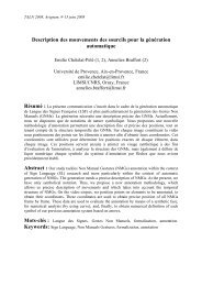
the bug are manipulated. The general lifecycle of bugs 9 in Bugzilla is shown in<br />
Figure 2. A bug is usually reported by an end user, and starts in the state “UN-<br />
CONFIRMED”. When a developer successfully reproduces the bug, it moves to<br />
the “CONFIRMED” state. The bug can them be assigned to a developer who will<br />
develop a fix, while the bug is in the state “ASSIGNED” or “IN PROGRESS”.<br />
Eventually, the developer finds a fix, and the bug is marked as “RESOLVED”,<br />
and moves to the state “VERIFIED” when someone from the quality assurance<br />
team confirms that the problem has been actually solved (with no regression)<br />
by the provided fix.<br />
For any particular bug, a custom collaboration setup can be created, to account<br />
<strong>for</strong> its peculiarities. As an illustration, we will study bug number 461304,<br />
titled “Loading URL by pressing ENTER on already present URL in location<br />
bar doesn’t maintain URL encoding” 10 . Simply put, this bug is a character-set<br />
encoding issue when selecting an entry in the drop-down menu that the browser<br />
shows when typing web URLs in the address bar.<br />
9 http://www.bugzilla.org/docs/tip/en/html/lifecycle.html<br />
10 https://bugzilla.mozilla.org/show_bug.cgi?id=461304<br />
6
Fig. 2: The lifecycle of a bug in BugZilla (Source: BugZilla Documentation [10])<br />
4.2 In<strong>for</strong>mal Description<br />
Bug 461304 has been reported Kai de Leeuw, in October 2010. José Jeria confirmed<br />
the bug, and added this was a windows-only issue. Mike Beltzner, a<br />
release driver at Mozilla, flagged the bug as “blocking-firefox3.5-”, which means<br />
that someone proposed that this particular bug be resolved be<strong>for</strong>e Firefox 3.5<br />
ships, and the release driver decided it should not block the release. Another<br />
release driver, Dietrich Ayala, flagged it as “wanted-firefox3.6+” which means<br />
he wants that bug to be resolved be<strong>for</strong>e Firefox 3.6 is released (by this will not<br />
block the release if it is not). Mike Beltzner then explicitly asked Gavin and<br />
Madark to localize the bug. Gavin found a conflict between the system encoding<br />
in windows (Windows-1252), and the encoding of natively used <strong>for</strong> URLs in<br />
Firefox (UTF-8).<br />
While investigating, Mike Beltzner suggested that this bug be marked a duplicate<br />
of bug 333859. But it became clear later that fixing bug 333859 will have<br />
too far reaching consequences (compatibility breaking). Another bug, 393246,<br />
was identified, as another duplicate, and fixing it will have less broad consequences.<br />
So it was decided to fix bug 393246, which will also fix the original bug<br />
461304.<br />
7
All the a<strong>for</strong>e mentioned people (and many others) were added to the “CC<br />
list” of the bug, meaning that they get emailed whenever a change is made to<br />
the bug in BugZilla.<br />
4.3 Description Using CM_SPEM Concepts<br />
There are a number of actors involved:<br />
– Kai de Leeuw is a user<br />
– José Jeria, Gavin, and Madark are developers<br />
– Mike Beltzner and Dietrich Ayala are release drivers<br />
A number of actor specific tasks can be identified:<br />
– “Report Bug”, carried out by the user Kai de Leew. Note that in this particular<br />
case, the task is identified, then affected to someone who carries it<br />
out. The user just stumbles upon the bug during normal browser usage,<br />
and decides to report it. Thus, this actor specific task in the model merely<br />
records something that has been done. This demonstrates how some tasks<br />
in a project cannot explicitly appear in a process model which exclusively<br />
focuses on planning.<br />
– “Confirm bug”, carried out by developer José Jeria.<br />
– “Identify bug cause”, carried out by Gavin<br />
– “Fix bug”, which will be carried out by the developer assigned to the bug<br />
(as of today, no one has been assigned to this bug).<br />
– “Confirm fix” which will be carried out by a member of the QA (Quality<br />
Assurance) team. Note that this actor is not yet identified, as bugs are usually<br />
fixed be<strong>for</strong>e a QA team member (depending on his workload and his area of<br />
expertise) reviews it <strong>for</strong> fix confirmation.<br />
The conversation happening around the bug, depending on how it is recorded,<br />
can be considered as an artifact on its own. In the case of BugZilla, the conversation<br />
is stored in BugZilla’s database, outside of the actual repository. Thus,<br />
we focus only on the artifacts impacted by the bug:<br />
– The file 11 which tracks user preferences (URL encoding can be specified as<br />
a preference in Firefox).<br />
– The file which handles URL encoding in Firefox 12<br />
Each copy of these files in a developer directory is an actor specific artifact<br />
on its own, which can evolve independently of others. Typically, the copy in the<br />
repository of the developer assigned to the bug will evolve first, and the changes<br />
made will be sent to an integrator (not shown in the actor list <strong>for</strong> simplicity).<br />
Some CM_SPEM relations can be identified as well in this situation:<br />
11 seamonkey/source/modules/libpref/src/init/all.js<br />
12 docshell/base/nsDefaultURIFixup.cpp<br />
8
– The actor specific task “Identify bug cause” can be carried out only when<br />
“Confirm bug” is complete (in other words, no developer is assigned to work<br />
on a bug be<strong>for</strong>e it has been reproduced by the Firefox team). This is an<br />
ActorSpecificTaskRelationship.<br />
– The user that reported the bug can provide feedback on the fixes proposed<br />
by the developer assigned to the bug (practically, it means every time the<br />
developer introduces a patch <strong>for</strong> that bug, the user can test it, and report<br />
results). This is an ActorRelationship.<br />
– In this particular case, as another bug was marked as a duplicate of the<br />
original bug, yet another ActorRelationship holds between the assignee of<br />
the original bug and the assignee of the duplicate bug. The latter, after<br />
fixing the bug assigned to him, must in<strong>for</strong>m the <strong>for</strong>mer (so that the orginal<br />
bug can also be marked as resolved). This particular relationship is already<br />
implemented by BugZilla.<br />
The above relations can materialize in a number of ways. For example,<br />
BugZilla has a feature called the “CC list”, which contains the email addresses<br />
of people who must be notified by email each time there is a significant change<br />
to a bug (like a change of state). The content of the CC list can be automatically<br />
derived from the above relations (by deriving all involved actors from the<br />
relationships, and then retrieving their email addresses).<br />
4.4 Other Exploitation Possibilities<br />
In this section, we showed how in<strong>for</strong>mation stored into CM_SPEM models can<br />
be used to provide a BugZilla-like functionality. Other possible usage scenarios<br />
include:<br />
– Automatically configure development environments (editors, version control<br />
systems, …).<br />
– Extract visualizations which helps practitioners understand what is going on.<br />
Example include displaying how connected people are by their work (which<br />
helps improve the organization of the team), or how much work load a person<br />
has at a given moment. Field studies in software engineering can also reuse<br />
this data.<br />
– Provide notifications. Relationships can be used to send useful in<strong>for</strong>mation to<br />
the people who need it (the “CC list” in the case of BugZilla is an example).<br />
While in<strong>for</strong>mation is desirable, practitioners can easily become drowned in<br />
irrelevant in<strong>for</strong>mation. The notifications sent can be filtered by considering<br />
the semantics of the relationships each participant is involved in.<br />
– In<strong>for</strong>m people of what their peers are actually currently doing, so they can<br />
know when they can interrupt them, and when they had better wait.<br />
5 Related Works<br />
Previous contributions of interest to our work relate to flexible instantiation of<br />
process models, extending process metamodels like SPEM to allow a more pre-<br />
9
cise definition of process models, and giving practitioners the ability to enhance<br />
process models with their evolving understanding of what they are doing.<br />
Killisperger et al., developed a framework <strong>for</strong> flexible process instantiation [8].<br />
The goal is to assist step-by-step tailoring and instantiation of generic and complex<br />
process models. While the progressive approach is shared by our proposal,<br />
they focus on constraining tailoring and instantiation (syntactic and organizational<br />
constraints), while we focus on supporting collaboration.<br />
There have been other ef<strong>for</strong>ts to extend SPEM. For example, [14] defines a<br />
<strong>for</strong>malism based on petri nets geared towards precise definition of MDE process<br />
models and process execution tracking. It however ignores resource allocation<br />
and roles definition, and concentrates on process steps (described with links,<br />
models, flow, resource, etc.) This <strong>for</strong>malism is more detailed than SPEM, but<br />
follows the same “define and execute” approach.<br />
Witshel et al. [17] identified the need to make business process execution<br />
more flexible. They start from the insight that – while offering valuable context<br />
in<strong>for</strong>mation – traditional business process modeling approaches are too rigid and<br />
inflexible to capture the actual way processes are executed. This is also the case<br />
in software engineering, where the execution is even less predictable. The paper<br />
explores how practitioner knowledge can be leveraged to enhance BPMN<br />
[12] process models, by allowing workers to leave semi-structured comments on<br />
BPMN activities. While this functionality is not natively present in our metamodel,<br />
it could be leveraged by considering our concepts (actor, actor specific<br />
task, actor specific artifact) and their relations as a way of annotating activities<br />
with the details of their collaborative execution.<br />
The ISO/IEC 24744 standard (Software Engineering – Metamodel <strong>for</strong> Development<br />
Methodologies) [7] is a metamodel which addresses some of the rigidity<br />
of SPEM. Its levels, metamodel, method, and endeavour, roughly correspond to<br />
the metamodel, model, and process instance levels in SPEM. However, ISO/IEC<br />
24744 has the ability to represent a concept defined at the metamodel level directly<br />
at the endeavour level (SPEM’s process instance level) and replaces rigid<br />
“instance-of” relations with representation relations. This has been shown[5] to<br />
be better suited to agile development and progressive decision-making in software<br />
projects, which makes our contribution on the ad-hoc nature of collaboration<br />
similar to the ISO/IEC 24744 ef<strong>for</strong>t. Besides the fact that ISO/IEC does<br />
not explicitly address the issue of collaboration, the choice of SPEM as a starting<br />
point has been motivated by project context (SPEM closely follows the model<br />
driven engineering approach, which is a central theme in the wider context of<br />
this work).<br />
In [6], Grudin et al. proposed a methodology <strong>for</strong> the design of collaborative<br />
environment which is halfway between the top-down approach of put-all-theknowledge-in-at-the-beginning<br />
and the bottom up approach of just-provide-anempty-framework.<br />
Witshel et al. [17] used this approach to design a “task pattern”<br />
<strong>for</strong>malism (task patterns are defined as “abstractions of tasks that provide<br />
in<strong>for</strong>mation and experience that is generally relevant <strong>for</strong> the task execution. By<br />
abstraction we mean common features of a family of similar tasks, which aim<br />
10
at the same goals under similar conditions”). Task patterns are instantiated by<br />
assigning real persons to the positions defined in the task pattern (concerned<br />
people can refuse or accept). A user can enhance a task pattern while executing<br />
it. The enhancements are stored locally, reused automatically <strong>for</strong> subsequent<br />
instances of the task pattern, and can be published so others can use it.<br />
In [1], Alegria et al. use three perspectives (views: role, task, work product) to<br />
visualize process models, and discover their defaults. This visualization approach<br />
could be exploited in our proposition by applying it to actors, actor specific task,<br />
and actor specific artifacts, so as to provide a precise and hopefully insightful<br />
view into the actual execution of a process model.<br />
6 Conclusion<br />
This work introduced CM_SPEM, a SPEM extension <strong>for</strong> the description of adhoc<br />
collaboration work. Our guiding principle is that collaboration should be<br />
conceptualized using the ideas most familiar to people collaborating. This is<br />
reflected in our choice of concepts and the way they are combined.<br />
We showed, on a real world example, that in<strong>for</strong>mation on collaboration usually<br />
becomes gradually available, which makes it impossible to provide all the<br />
details of collaborative process models at the start of project. Instead, we advocate<br />
a feedback loop between how collaboration unfolds in reality and what is<br />
(initially) recommended by the model.<br />
While enriching process models is useful, this could become time-consuming<br />
<strong>for</strong> practitioners. However, adding collaboration in<strong>for</strong>mation to process models<br />
need not be done by hand, but could be partially automated using the<br />
CM_SPEM API. For example, ActorRelationships could be identified by analysing<br />
version control history, and their addition suggested to practitioners.<br />
A graphical notation <strong>for</strong> CM_SPEM models, and a visual editor based on<br />
that notation have been developed, but are not presented here due to insufficient<br />
space. The editor is based on Eclipse, and provides some consistency checks<br />
when editing CM_SPEM models. There is also a project plan generator <strong>for</strong><br />
Microsoft Project and GanttProject in the making. We are currently <strong>for</strong>malizing<br />
the behavioral aspects of ad-hoc collaboration as an extension of CM_SPEM.<br />
Other future directions include the definition of a complete query API <strong>for</strong><br />
CM_SPEM process models (used by development support tools to extract in<strong>for</strong>mation<br />
from CM_SPEM models), and develop an ecosystem of tools which<br />
materialize the ultimate goal of our metamodel.<br />
Acknowledgment<br />
This ef<strong>for</strong>t is part of the Galaxy Project, funded by ANR – France.<br />
11
References<br />
1. Alegría, J., Lagos, A., Bergel, A., Bastarrica, M.: Software Process Model<br />
Blueprints. New Modeling Concepts <strong>for</strong> Today’s Software Processes pp. 273–284<br />
(2010)<br />
2. Booch, G., Brown, A.: Collaborative development environments. Advances in Computers<br />
59, 1–27 (2003)<br />
3. Cherry, S., Robillard, P.: The social side of software engineering–A real ad hoc<br />
collaboration network. International journal of human-computer studies 66(7),<br />
495–505 (2008)<br />
4. Coulette, B., Kedji, K., Nassar, M.: Vers un métamodèle pour la représentation<br />
des procédés idm collaboratifs. Proc. of 7ièmes Journées sur l’Ingénierie Dirigée<br />
par les Modèles (June 2011)<br />
5. Gonzalez-Perez, C.: Supporting situational method engineering with iso/iec 24744<br />
and the work product pool approach. Situational Method Engineering: Fundamentals<br />
and Experiences pp. 7–18 (2007)<br />
6. Grudin, J., McCall, R., Ostwald, J., Shipman, F.: Seeding, Evolutionary Growth,<br />
and Reseeding: The Incremental Development of Collaborative Design Environments.<br />
Coordination theory and collaboration technology p. 447 (2001)<br />
7. Henderson-Sellers, B., Gonzalez-Perez, C.: Standardizing methodology metamodelling<br />
and notation: An ISO exemplar. In<strong>for</strong>mation Systems and e-Business Technologies<br />
pp. 1–12 (2008)<br />
8. Killisperger, P., Stumptner, M., Peters, G., Grossmann, G., Stückl, T.: A <strong>Framework</strong><br />
<strong>for</strong> the Flexible Instantiation of Large Scale Software Process Tailoring. New<br />
Modeling Concepts <strong>for</strong> Today’s Software Processes pp. 100–111 (2010)<br />
9. Mistrík, I., Grundy, J., van der Hoek, A., Whitehead, J.: Collaborative Software<br />
Engineering: Challenges and Prospects. Collaborative Software Engineering p. 389<br />
(2010)<br />
10. Mozilla: The bugzilla project. http://www.bugzilla.org/ (2011)<br />
11. OMG: Software process engineering metamodel, version 2.0.<br />
http://www.omg.org/spec/SPEM/2.0/ (2007)<br />
12. OMG: Business process model and notation, version 1.2.<br />
http://www.omg.org/spec/BPMN/1.2/ (2009)<br />
13. OMG: Object constraint language. http://www.omg.org/spec/OCL/2.2/ (2010)<br />
14. Porres, I., Valiente, M.: Process definition and project tracking in model driven<br />
engineering. Product-Focused Software Process Improvement pp. 127–141 (2006)<br />
15. Robillard, P., Robillard, M.: Types of collaborative work in software engineering.<br />
Journal of Systems and Software 53(3), 219–224 (2000)<br />
16. Roschelle, J., Teasley, S.: The construction of shared knowledge in collaborative<br />
problem solving. NATO ASI Series F Computer and Systems Sciences 128, 69–69<br />
(1994)<br />
17. Witschel, H., Hu, B., Riss, U., Thönssen, B., Brun, R., Martin, A., Hinkelmann,<br />
K.: A Collaborative Approach to Maturing Process-Related Knowledge. Business<br />
Process Management pp. 343–358 (2010)<br />
12
A <strong>Framework</strong> <strong>for</strong> <strong>Integrating</strong> <strong>ESL</strong> <strong>Tools</strong><br />
Ali Koudri 1 , Teodora Petrisor 1 , Joel Champeau 2 , and Vincent Leilde 2<br />
1 Thales Research and Technology<br />
2 ENSTA Bretagne STIC/IDM<br />
Abstract. Today embedded systems are complex and their development<br />
is based on the use of a large set of tools. Although point to point<br />
tool integration can be efficient, it is not very well adapted to changing<br />
because it remains costly and human expensive. To solve this problem,<br />
several approaches on tool integration have been proposed. Even<br />
if those approaches handle the flexibility and the obsolescence issues,<br />
the tool synergy cannot still be achieved due to major problems such as<br />
technological or semantic gaps. Recently, new techniques such as model<br />
based engineering and communities such as OSLC have emerged. They<br />
represent a promising approach <strong>for</strong> significant improvement of integration<br />
frameworks. In this paper, we present the basics <strong>for</strong> an integration<br />
framework supporting HW/SW co-design development that takes benefits<br />
from modeling and current standards. This work is part of the iFEST<br />
ARTEMIS project.<br />
1 Introduction<br />
Today, development of real-time embedded systems is more and more stressed by<br />
higher demands in terms of functionalities as well as economical factors pushing<br />
the competitiveness by reducing costs and time to market. Indeed, developing,<br />
producing and maintaining embedded systems raise a number of challenges since<br />
they are inherently heterogeneous (mixing software and hardware parts, analog<br />
and digital parts, etc.). The development of embedded systems constitutes actually<br />
a multidisciplinary endeavor as it involves the cooperation of a large number<br />
of experts from various domains over the various stage of the development (Requirements<br />
Engineering and Analysis, Design and Implementation, Verification<br />
and Validation, Lifecycle Management). As such, stakeholders of the process<br />
have to face issues related to external communication (customer) as well as<br />
internal communication (between the various experts involved in the development).<br />
Those issues have a really strong impact on the cost, the time-to-market<br />
and the quality of the delivered products.<br />
In this context, we think that having more fluid communication between<br />
the various stakeholders would help to improve the overall productivity and the<br />
quality of the products. To achieve this goal, we shall consider the two most<br />
important communication styles that occur in any development project: the<br />
oral communication and the communication relying on the exchange of artifacts<br />
produced by the various tools used during the process lifecycle (MS-Word, MS-<br />
Excel, Doors, GNU C Compiler, etc.). The first one is addressed by the natural<br />
13
language processing and is out of the scope of this paper. Rather, we address in<br />
this paper the improvement of the communication between the various kinds of<br />
tools generally used in a co-design process targeting the development of real-time<br />
embedded systems. By communication, we mean ”intelligent communication”<br />
that takes into account not only syntactic considerations but also semantic ones<br />
as well as lifecycle issues. We present in this paper the basics <strong>for</strong> a framework<br />
dedicated to integrating <strong>ESL</strong> (Electronic System Level) tools which aims not<br />
only to reduce costs and time-to-market, but also to improve the quality of the<br />
products through early defects detection and correction. This work is done in<br />
the context of the iFEST ARTEMIS project [8].<br />
This paper is organized as follow: the second section presents the background<br />
and the motivations of our work; the third section presents the basis <strong>for</strong> the integration<br />
framework plat<strong>for</strong>m; the fourth section discusses the expected benefits<br />
of the integration framework plat<strong>for</strong>m; finally, the conclusion draws the current<br />
state of our work and its perspectives.<br />
2 Background and Motivation<br />
In nowadays practices, tools supporting the development of in<strong>for</strong>mation systems<br />
are not very well integrated. This is particularly the case <strong>for</strong> HW/SW co-design,<br />
which often addresses complex issues related to multi-cores and parallelism, and<br />
where tools are still sparse and not very mature. An appropriate tool chain would<br />
allow engineering assets to be developed and/or reused, and applied <strong>for</strong> different<br />
contexts with different purposes. Indeed, development of real-time embedded<br />
systems requires establishing tool chains tailored to fit production characteristics<br />
as well as business organization and concerns. Since requirements and supporting<br />
tools can evolve during the process lifecycle, such tool chains require to be<br />
maintained easily and seamlessly. For example, the necessity to reduce cost can<br />
push companies to change a tool by another one supporting the same features<br />
during one project. Such change can raise numerous risks related to bugs or<br />
learning curves that are potentially costly. This assertion is also right <strong>for</strong> the<br />
introduction of a new version of a given tool. Besides, lifecycle support represents<br />
an important issue as re-engineering can occur when hardware components<br />
become obsolete or when new software versions are developed and deployed.<br />
In this context, the adoption of a tool integration technology supporting the<br />
adding, the removing and the replacement of tools to support a given process<br />
is of a great necessity. <strong>Tools</strong> integration should enable smooth evolution from<br />
one generation to the next, with much lower ef<strong>for</strong>t than it takes today, retaining<br />
the best of previous generations and adding upgrades in a <strong>for</strong>mal environment,<br />
minimizing the risks. Moreover, if such integration technology can also support<br />
process orchestration, it would greatly improve the quality of the process and<br />
thus, the resulting products. <strong>Tools</strong> integration has been studied by many scientific<br />
and technological communities since the 70s [5, 14, 4, 10]. For instance,<br />
according to [5, 14], there are various levels <strong>for</strong> tools integration:<br />
14
– Data integration is concerned with the provision of mechanisms that support<br />
the sharing of data among tools and managing the relationships among<br />
data objects produced by different tools. This kind of integration deals with<br />
traceability, consistency, completeness and the granularity of the in<strong>for</strong>mation<br />
being exchanged,<br />
– Control integration refers to the ability of tools to per<strong>for</strong>m notifications to<br />
other tools as well as to run other tools,<br />
– Presentation integration is concerned with providing a common ”look and<br />
feel” <strong>for</strong> a number of tools from the user’s perspective,<br />
– Process integration is concerned with the roles of tools in the overall development<br />
process,<br />
– Plat<strong>for</strong>m integration is concerned with basic inter-operability among tools,<br />
traditionally referring to system services provided by a middleware or an<br />
operating system.<br />
Not all the dimensions have to be considered <strong>for</strong> a given project, it depends<br />
mainly on the organization and the project characteristics. For example, presentation<br />
integration may not be fully desirable when different disciplines already<br />
have established their ways of presenting in<strong>for</strong>mation. There can also be some<br />
possible dependencies and overlapping between those dimensions. In the following<br />
list, we give a brief overview of the main technologies supporting such<br />
capability:<br />
– Model-driven engineering includes the use of metamodels and model trans<strong>for</strong>mations<br />
to support tool integration. This has been a rapidly evolving area<br />
<strong>for</strong> the past 10 years and it represents a promising approach <strong>for</strong> systematic<br />
tool integration [11],<br />
– Process-driven tool integration emphasizes <strong>for</strong>malized descriptions of processes.<br />
Execution of such models allows process orchestration into which the<br />
process execution engines per<strong>for</strong>ms actions upon tools and artifacts [3],<br />
– Web-services based tool integration uses standardized communication protocols<br />
developed in the context of the internet and web <strong>for</strong> the purpose of<br />
tools integration [2],<br />
– Modular tools integration relies on extensible plat<strong>for</strong>ms supporting the definition<br />
of modular tools as new extensions. For instance, the Eclipse plat<strong>for</strong>m<br />
[7] complies with such a definition,<br />
– Database and life-cycle management approaches rely on structured in<strong>for</strong>mation<br />
management. They typically use centralized repositories and, sometimes,<br />
standardized exchange <strong>for</strong>mats.<br />
While some of the current technologies have a focus on providing support <strong>for</strong><br />
integrating engineering tools, this is <strong>for</strong> example true <strong>for</strong> Modelbus [13], others<br />
such as Eclipse or Jazz [6] are more agnostic and provide basic support <strong>for</strong> integrating<br />
any type of tool. Although all those technologies have their pros and their<br />
cons, they generally address one or two dimensions among the ones presented<br />
above. Then, through this work, we aim to cross a step <strong>for</strong>ward and propose a<br />
solution based on a real separation of concerns allowing the seamless integration<br />
15
of any tool into a co-design tool chain. To achieve this goal, we propose first to<br />
characterize any tool used in a co-design according several viewpoints. Later, we<br />
aim to support process orchestration based on automated enactment of process<br />
models.<br />
In order to reach our objectives, we have defined the following intermediate<br />
objectives:<br />
– select, and on very specific occasions develop, interoperable tools <strong>for</strong> tool<br />
chains,<br />
– automate the trans<strong>for</strong>mation of tool exchange data when going from one<br />
phase in the engineering life cycle to the next one,<br />
– select, and develop as needed, advanced integration technologies which shall<br />
be open, tool independent, and preferably standardized,<br />
– automate process steps, i.e. automate one or more development activities.<br />
We think that integration technologies must support both available and future<br />
tools, enabling them to be integrated into process flows with minimal disruption<br />
and ef<strong>for</strong>t. In this context, the iFEST project will emphasize the use of<br />
standardized technologies and will promote and support standardization of its<br />
integration technologies.<br />
3 Basis <strong>for</strong> the Integration <strong>Framework</strong><br />
As mentioned in the previous section, our integration framework aims to provide<br />
means <strong>for</strong>:<br />
– The development of complex real-time embedded systems requiring the use of<br />
heterogeneous and multi-core plat<strong>for</strong>ms, according to a well-defined HW/SW<br />
co-design process,<br />
– The support of all the development phases from requirements to the production<br />
of hardware and software, including the life cycle of the process /<br />
product / system. This involves the integration of tools in such a way that<br />
the interfaces are tool independent.<br />
We believe it will take a reasonable and straight-<strong>for</strong>ward ef<strong>for</strong>t to set up a<br />
tool chain supporting each phase of a co-design process. The main reason is that<br />
there are plenty of tools available <strong>for</strong> each phase of a co-design process. Then,<br />
our approach to characterize tools used in such process will be pragmatic: we<br />
start by analyzing the needs of the different industrial partners involved in the<br />
project, representing different domain areas (aerospace, automotive, railways,<br />
robotic), and the tool they use <strong>for</strong> each phase. Based on this idea, we have<br />
established a map of used tools <strong>for</strong> each partner at each main phase of their<br />
process (Requirement Engineering and Analysis, Design and Implementation,<br />
Verification and Validation, Lifecycle Support).<br />
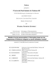
The figure 1 shows an example of such map <strong>for</strong> the development of a radar<br />
system. We can notice in this figure that a strong emphasis has been put on the<br />
life cycle issues. Indeed, the various aspects of the life cycle have considerable<br />
16
RE&A<br />
Matlab /<br />
Simulink<br />
D&I<br />
GNU C<br />
Compiler<br />
ISE<br />
Design Suite<br />
IRQA<br />
Word<br />
HP QC<br />
Windriver<br />
Workbench<br />
IEC-61131<br />
Tool<br />
RTW<br />
Embedded Coder<br />
iFEST <strong>Framework</strong><br />
Matlab /<br />
Simulink<br />
dSpace<br />
ModelSim<br />
Windriver<br />
SVN HP QC<br />
MS Team<br />
Workbench<br />
Foundation<br />
Trac<br />
Optima<br />
EDASL<br />
V&V<br />
Klocwork<br />
Lifecycle support<br />
Fig. 1. Co-design <strong>Tools</strong> <strong>for</strong> developing a Radar application<br />
impacts not only on the engineering process but also on the properties of the<br />
product itself from a structural and architectural point of view. These aspects<br />
are costly and difficult to change, once the product has been released, if they<br />
have not been considered up-front. This leads to the concept of Design <strong>for</strong> Life<br />
Cycle Support considering issues related to the major phases of development<br />
and/or evolution of the product.<br />
Regarding life cycle issues, we aim to achieve advances in the following areas:<br />
– Design <strong>for</strong> Changeability The ability to easily change system components<br />
(HW or SW) due to obsolescence, malfunctioning or the introduction of an<br />
additional functionality. The changes must be carried out in a cost effective<br />
and controlled fashion, i.e. they must not lead to quality or regression issues.<br />
The changes are not limited to the product and associated artifacts but they<br />
also include individual tools within the tool chains. Since tools are also part<br />
of the system environment, they may themselves be subject to obsolescence.<br />
Design <strong>for</strong> Changeability requires tooling support and automation of the<br />
change management process to allow rigorous and detailed tracking in terms<br />
of change types, reason, impact, ownership, etc.<br />
– Design <strong>for</strong> Traceability Traceability is the degree to which a relationship can<br />
be established between two or more artifacts of the product life cycle, especially<br />
establishing relationships between predecessors and successors (e.g.<br />
requirements and design, design and code, etc). The objective of iFEST is<br />
to allow <strong>for</strong> <strong>for</strong>ward and backward traceability,<br />
– Design <strong>for</strong> Modularity Modularity refers to the degree to which system<br />
components can be separated and re-integrated. Design <strong>for</strong> Modularity aims<br />
at minimizing unintended interactions between components, hence pushing<br />
towards the decoupling of interfaces. This has major benefits in terms of<br />
life cycle support: improving maintenance and quality as well as enabling<br />
concurrent engineering shortening time to market.<br />
17
The real challenge then is to provide a framework enabling the establishment<br />
of an HW/SW tool chain in a process centric approach based on the use of models<br />
and supporting life cycle management. The tool integration framework will foster<br />
architectural design space exploration in a cost effective design while reducing<br />
risks related to tools and communication between tools. A major innovation<br />
in this respect is the envisioned integration of traditional HW/SW co-design<br />
tools (with <strong>for</strong>malized models and partitioning schemes) and tools that typically<br />
belong to the MDE-world (with meta-modeling and trans<strong>for</strong>mations). Indeed,<br />
the use of model driven engineering will allow us to go from abstract modeling<br />
to hardware design and software coding in a cost-effective manner. Meanwhile,<br />
our goal is not really about developing new modeling technologies, nor about<br />
developing new tools as such. Rather, we are more concerned with establishing<br />
tool chains through the use of integration technology which is tool-independent.<br />
Thus, our main contribution will be in the definition and implementation<br />
of models and meta-models both <strong>for</strong> the targeted application domains and <strong>for</strong><br />
existing tools. Supported by the Integration <strong>Framework</strong>, these models and metamodels<br />
will allow different tool chains to be integrated and managed. Besides,<br />
meta-modeling approaches will be used to automatically implement necessary<br />
tool chain interfaces providing the search <strong>for</strong> interoperability of tools.<br />
Today, the solution we are developing has to face 3 issues: the interfacing<br />
between tools, the communication between tools and the orchestration of tools.<br />
For each of those issues, we have investigated several possible solutions. In the<br />
following paragraph, we present the solutions we have chosen to handle those<br />
issues. These solutions represent the basic building blocks used in the chosen<br />
architecture implementing our integration framework as illustrated in the figure<br />
2 and detailed below.<br />
Process<br />
Orchestration<br />
iFEST <strong>Framework</strong><br />
Life cycle<br />
Management<br />
OSLC<br />
OSLC<br />
OSLC<br />
Tool 1 Adaptor<br />
Tool 2 Adaptor<br />
Tool n Adaptor<br />
Tool 1<br />
Viewpoints<br />
Tool 2<br />
Viewpoints<br />
Tool n<br />
Viewpoints<br />
in/outTrans<strong>for</strong>mations<br />
Tool 1<br />
in/outTrans<strong>for</strong>mations<br />
Tool 2<br />
in/outTrans<strong>for</strong>mations<br />
Tool n<br />
Fig. 2. Architecture of the Integration Plat<strong>for</strong>m<br />
The adaptor component handles the adaptation of tools in order to facilitate<br />
its interfacing with other tools of the tools chain. The basic idea of this component<br />
is to characterize tools according to several viewpoints because we are<br />
18
not only interested on how input / output data are <strong>for</strong>matted, but also on their<br />
interpretation / meaning. For instance, the figure 3 shows the main aspect of our<br />
tool viewpoint metamodel. We use then this metamodel to characterize any tool<br />
used in a co-design flow. The figure 4 shows an example of a characterization of<br />
the SpearDE tool [9] according to two viewpoints (architecture and mapping).<br />
Fig. 3. Excerpt of the tool viewpoint metamodel<br />
Fig. 4. Example of SpearDE tool viewpoints<br />
While the tool viewpoint metamodel allows us to characterize the interfaces<br />
of the tools, we need mechanisms to support communication between those tools,<br />
possibly over a wide network (internet). For this purpose, we have chosen to use<br />
the OSLC (Open Services <strong>for</strong> Lifecycle Collaboration) services [1]. The OSLC<br />
19
initiative is a community based ef<strong>for</strong>t aiming to standardize different components<br />
<strong>for</strong> tool integration. It provides a set of specifications organized into topics (Requirement<br />
management, change management, etc.), based on core specification<br />
and guidelines. The OSLC does not target tools integration, but rather specify<br />
how tool data are interfaced externally. In this approach, the resources can be<br />
provided and requested using web services.<br />
Regarding the last point, e.g. process orchestration, we have made the choice<br />
of enacting process models. More precisely, we propose to use SPEM [12] to<br />
model co-design processes and integrate a process model execution engine into<br />
the framework in order to support a fine process orchestration, enabling or disabling<br />
tools according to the current state of the process execution. This last<br />
topic is a really hot one and is out of the scope of this paper. In the next section,<br />
we discuss what the main benefits we expect from this proposition are.<br />
4 Expected Benefits<br />
The proposition presented in the previous section contributes to the transition<br />
from separate sectorial, vertically structured markets to a horizontally structured<br />
market. Indeed, the open tool integration technologies enables horizontally<br />
structured market of embedded system tools as it intends to be applicable across<br />
several domains and markets. Enabling exchange of individual tools will open<br />
market opportunities <strong>for</strong> tool vendors. Enabling exchange of individual tools<br />
is also expected to stimulate cross-domain tools usage since tools used in one<br />
domain can be more easily used in the tool chain of another domain.<br />
We expect that tools that are exchangeable in a tool chain will lower the<br />
threshold <strong>for</strong> buying tools. Thus, we think this project will also stimulate the<br />
emergence of a new innovation ecosystem around integration frameworks. Indeed,<br />
one of the final goals of this project is to produce a set of interfaces and<br />
service definitions that will be pushed to become standards. This will be facilitated<br />
by the strong links of the project partners with standards bodies. For<br />
instance, iFEST participants have been successfully involved in the standardization<br />
of MARTE and SPEM profiles.<br />
At last, this project will demonstrate:<br />
– a cost reduction potential of 20% <strong>for</strong> the partners’ system design. It will<br />
achieve this by automating some of the processes that are not yet mainstream,<br />
such as trans<strong>for</strong>ms from plat<strong>for</strong>m independent to plat<strong>for</strong>m specific<br />
models, design space exploration, and broadening target hardware options<br />
(multi-core).<br />
– a potential time to market decrease of 20% <strong>for</strong> the partners. A well-functioning<br />
tool chain will reduce both the time <strong>for</strong> setting up an effective development<br />
environment and even more the time spent <strong>for</strong> development.<br />
– a potential of 20% <strong>for</strong> cost of poor quality <strong>for</strong> the partners. A well-functioning<br />
tool chain will avoid errors which todays manual processes introduce when<br />
going from one phase in the engineering life cycle to the next one. The<br />
tool integration solutions will enable use of analysis and synthesis tools that<br />
20
increase the chances of removing errors prior to product release, and thus<br />
improving development efficiency.<br />
The assessment of the Integration <strong>Framework</strong> will be realized according to<br />
several evaluation criteria set by the industrial partners of the project. It will<br />
be measured through the realization of real industrial use cases from different<br />
domains (software radio, aerospace, railways, etc.). Then, based on their strong<br />
experience, the industrial partners will able to say at the end of the project<br />
whether the Integration <strong>Framework</strong> has achieved its goal.<br />
5 Conclusion<br />
A number of interesting technologies have been studied to achieve the tool integration<br />
framework. The technologies stem from a number of different areas<br />
including model-driven engineering, and the IT and web domains. All of the studied<br />
plat<strong>for</strong>ms utilize variants of distributed architectures over standard protocols<br />
and middlewares. All approaches strive in different ways towards modularization<br />
and in achieving loose coupling and configurability of integration.<br />
While some plat<strong>for</strong>ms have a focus on providing support <strong>for</strong> integrating engineering<br />
tools, other are more agnostic and provide basic support <strong>for</strong> integrating<br />
any type of tool. Besides those ”basic” tool integration services, other services<br />
like user and project administration can be delivered as predefined services.<br />
Moreover, process modeling support is almost available in all of the plat<strong>for</strong>ms,<br />
at different levels of granularity. Meanwhile, process execution is still an area in<br />
progress.<br />
In this paper, we have presented the basics of our integration framework we<br />
aim to implement and standardize. This integration framework will allow the<br />
industry to compose a tool chain by combining tools from various vendors, and<br />
even open source tools. Later, we will integrate mechanisms <strong>for</strong> process orchestration<br />
in order to finely tune the usage of the tool over the process execution.<br />
Through this work, we aim to reduce costs and time to market and improve the<br />
quality of delivered products. This work is part of the iFEST project which is a<br />
European ARTEMIS project.<br />
References<br />
1. Open services <strong>for</strong> lifecycle collaboration, http://openservices.net/html/Home.html<br />
2. Aho, P., Mäki, M., Pakkala, D., Ovaska, E.: Mda-based tool chain <strong>for</strong> web services<br />
development. In: Proceedings of the 4th Workshop on Emerging Web Services<br />
Technology. pp. 11–18. WEWST ’09, ACM, New York, NY, USA (2009),<br />
http://doi.acm.org/10.1145/1645406.1645409<br />
3. Bendraou, R., Combemale, B., Cregut, X., Gervais, M.P.: Definition of an executable<br />
spem 2.0. In: Proceedings of the 14th Asia-Pacific Software Engineering<br />
Conference. pp. 390–397. APSEC ’07, IEEE Computer Society, Washington, DC,<br />
USA (2007), http://dx.doi.org/10.1109/APSEC.2007.38<br />
21
4. Brown, A., Feiler, P., Wallnau, K. (eds.): Past and future models of CASE integration<br />
(1992)<br />
5. Chung, C.M., Chow, L.R., Shih, T., Wang, Y.H., Lin, W.C., Chen, J.F.:<br />
Tool integration in a knowledge abstraction environment. In<strong>for</strong>mation Sciences<br />
105(1-4), 279 – 298 (1998), http://www.sciencedirect.com/science/article/B6V0C-<br />
3TKS65B-1B/2/a1f6c19d7f118884d25f1b82066dea91<br />
6. Datta, S., Sindhgatta, R., Sengupta, B.: Evolution of developer collaboration on<br />
the jazz plat<strong>for</strong>m: a study of a large scale agile project. In: Proceedings of the 4th<br />
India Software Engineering Conference. pp. 21–30. ISEC ’11, ACM, New York,<br />
NY, USA (2011), http://doi.acm.org/10.1145/1953355.1953359<br />
7. Eclipse: http://www.eclipse.org<br />
8. iFEST: Integration framework <strong>for</strong> embedded systems tools, http://www.artemisifest.eu/<br />
9. Lenormand, E., Edelin, G.: An industrial perspective: A pragmatic high-end signal<br />
processing design environment at thales. In: SAMOS-III, Computer Systems:<br />
Architecture, Modeling and Simulation (September 2003)<br />
10. Long, F., Morris, E.: An overview of pcte: A basis <strong>for</strong> a portable common tool<br />
environment. Tech. rep., CMU (1993)<br />
11. Marquardt, W., Nagl, M.: A Model-Driven Approach <strong>for</strong> A-posteriori Tool<br />
Integration, chap. 1, pp. 3–38. Springer-Verlag, Berlin, Heidelberg (2008),<br />
http://portal.acm.org/citation.cfm?id=1422985.1422987<br />
12. OMG: Software & systems process engineering meta-model specification, version<br />
2. Tech. rep., OMG (2008)<br />
13. Sriplakich, P., Blanc, X., Gervals, M.P.: Collaborative software engineering on<br />
large-scale models: requirements and experience in modelbus. In: Proceedings of<br />
the 2008 ACM symposium on Applied computing. pp. 674–681. SAC ’08, ACM,<br />
New York, NY, USA (2008), http://doi.acm.org/10.1145/1363686.1363849<br />
14. Wasserman, A.I.: Tool integration in software engineering environments. In: Proceedings<br />
of the international workshop on environments on Software engineering<br />
environments. pp. 137–149. Springer-Verlag New York, Inc., New York, NY, USA<br />
(1990), http://portal.acm.org/citation.cfm?id=111335.111346<br />
22
A Domain Specific Model to Support Model<br />
Driven Development of Business Logic<br />
Tobias Brückmann, Volker Gruhn<br />
paluno - The Ruhr Institute <strong>for</strong> Software Technology<br />
University of Duisburg-Essen, 45127 Essen, Germany<br />
{tobias.brueckmann, volker.gruhn}@uni-due.de<br />
Abstract. Despite of ongoing development of model-driven development<br />
approaches in industry and academia, we believe that there is a<br />
lack of support <strong>for</strong> the generation of business logic code from refined<br />
process models. In our work we developed a framework to support a<br />
consistent support of modeling and generation of business logic <strong>for</strong> in<strong>for</strong>mation<br />
systems. In this article, we analyse the modeling concepts of<br />
visual behavioral modeling languages. Based on the analysis results, we<br />
introduce a domain specific model (DSM) <strong>for</strong> business logic of in<strong>for</strong>mation<br />
systems. The DSM <strong>for</strong> business logic provides a compact and clear<br />
technical interface. It is used to connect visual modeling languages, model<br />
analysis tools, and code generators as part of our integrated framework.<br />
1 Introduction<br />
To provide a consistent support of model driven software development, we believe<br />
that an integrated framework considering all phases of a software process is<br />
needed (from early analysis and design until implementation and maintenance).<br />
There<strong>for</strong>e, at least following aspects have to be considered: (1) Visual software<br />
models have to support different modeling paradigms in different levels of detail;<br />
(2) Quality assurance tasks <strong>for</strong> complex visual software models have to support<br />
modelers in preventing a faulty and inconsistent model; and (3) A clear interface<br />
between visual software models and code generators is needed, in particular<br />
if several visual modeling languages and several code generators are deployed.<br />
Despite of ongoing development of model-driven development approaches in industry<br />
and academia as described in the related work section, we believe that<br />
in particular the business logic aspects of in<strong>for</strong>mation systems need to be better<br />
supported. In our work, we developed a framework that provides an integrated<br />
support of all phases of a development process. This includes business process<br />
modeling and system modeling, model analysis and verification of analysis and<br />
design models, generation of business logic code, and runtime assurance of the<br />
modeled business logic control flow and its constraints. The generation of structured<br />
process descriptions (such as BPEL) as required by workflow management<br />
systems are not focused (but not excluded). Additionally, we assume that the<br />
business logic of industrial in<strong>for</strong>mation systems often depends on external functions<br />
or systems such as web services, public APIs, or further systems of an<br />
enterprise application landscape.<br />
23
In our framework, a domain specific model (DSM) <strong>for</strong> business logic is used<br />
to provide a compact and clear interface between modeling languages and code<br />
generators. Based on the analysis of visual modeling languages <strong>for</strong> behavioral<br />
aspects of systems, we designed this domain specific model <strong>for</strong> business logic to<br />
support all relevant modeling concepts needed <strong>for</strong> business logic code generation<br />
of in<strong>for</strong>mation systems. After the discussion of related work in Sect. 2, we analyse<br />
several visual modeling languages <strong>for</strong> systems behavior in Sect. 3 be<strong>for</strong>e we<br />
define a domain specific model <strong>for</strong> business logic in Sect. 4. Then, we give a<br />
brief overview of the usage of the business logic DSM as part of a framework in<br />
Section 5 and conclude in Section 6.<br />
2 Related Work<br />
In general, we follow Waddington et al. who states in [17] that „multiple modeling<br />
notations and interpretations (views) are necessary to represent each of the<br />
different aspects of concern and to fulfill different roles within MCSD [Model-<br />
Centric Software Development] such as verification of correctness, human understanding<br />
through visual interpretation, and code generation”. In tool chains<br />
and frameworks <strong>for</strong> embedded systems (such as provided by Konrad et al. [8],<br />
) structural aspects are integrated with scenario models or state chart models<br />
or both, which are commonly applied behavioral modeling concepts <strong>for</strong> reactive<br />
systems. Ryndina et al. connected process and state modeling in [13] through<br />
generation of object live cycles based on process models, but they do not focus<br />
on an abstract model providing an integrated view. Gerth et al. provide in<br />
[4] a so-called “intermediate representation (IR)” of process models as abstract<br />
representation of process models and applied it <strong>for</strong> model change management<br />
purposes. However, this approach do not consider structural or state modeling<br />
concepts. Mohan et al. provides with their FlexFlow model in [9] an integration<br />
of structural and state modeling, but they do not consider process modeling<br />
aspects. However, <strong>for</strong> business logic generation <strong>for</strong> in<strong>for</strong>mation systems we need<br />
integrated model supporting process modeling (containing all actions and control<br />
flow specification), structural modeling (containing all business objects that<br />
are relevant during process execution) and state modeling (containing domain<br />
states of business objects and object live cycles).<br />
In context of modeling systems behavior there are several approaches that<br />
trans<strong>for</strong>m visual behavior diagrams into special purpose languages. One purpose<br />
<strong>for</strong> such trans<strong>for</strong>mation is to get a <strong>for</strong>mal-founded structure <strong>for</strong> automated model<br />
quality assurance. Target models are <strong>for</strong> example process algebras (e.g. Engels et<br />
al. in [3]) or Petri nets variants (as discussed by Stains in [15]) which are suitable<br />
<strong>for</strong> automated reasoning or simulation. However, the high level of abstraction<br />
of <strong>for</strong>mal models makes them difficult to handle them as technical interfaces<br />
<strong>for</strong> business logic code generators. Otherwise, in case of using domain specific<br />
behavioral models <strong>for</strong> code generation, they are designed <strong>for</strong> proprietary tool<br />
chains (such as FlexFlow [9] or J3 [18]) or specific target plat<strong>for</strong>ms (such as BPEL<br />
in [7], or Embedded Systems e.g. in [8]). As a difference to related approaches,<br />
24
with our DSM <strong>for</strong> business logic, we aim to support a compact and well-defined<br />
interface to connect different modeling languages, model trans<strong>for</strong>mation rules,<br />
and code generators without any dependency to modeling languages or target<br />
plat<strong>for</strong>ms. Approaches such as [2] also define and use intermediate models <strong>for</strong><br />
behavior modling of in<strong>for</strong>mation systems. However, we explicit consider state<br />
modeing in <strong>for</strong>m domain states in our approach.<br />
3 Analysis of Visual Behavior Models<br />
The following analysis of visual behavior models provides the basis <strong>for</strong> our domain<br />
specific model <strong>for</strong> behavior logic. For the analysis of major behavioural<br />
modeling concepts, we considered following visual modeling languages <strong>for</strong> process<br />
and systems behavior: eEPC [14], BPMN [11], Petri Nets [12] and Coloured<br />
Petri Nets [6], YAWL [16], and UML [10]. We dropped MSC [5], pure State<br />
Charts, and Data Flow diagrams <strong>for</strong> detailed analysis: MSCs focus only on scenarios<br />
and pure State Charts focus only on states. Data Flow diagrams contains<br />
agraphicaldepictionofdataflowthroughasystem,butonlyfromanabstract<br />
point of view. Model details such as order of processes, or control flows aspects<br />
are missing.<br />
Fig. 1 provides an tabular overview of modeling aspects and their support<br />
by visual modeling languages. In our analysis we focus on aspects of process<br />
modeling, structural modeling and state modeling concepts and their integration.<br />
Process Modeling Each analysed modeling language supports an atomic element<br />
that contains functions/actions/tasks that are executed during runtime of a process<br />
(see the first row in Fig. 1). It is named “function” in EPC, “task” in BPMN<br />
and YAWL, “action” in UML, and “transition” in Petri Nets. Moreover, “nesting”<br />
provides an opportunity <strong>for</strong> a more usable visual and logical structure that<br />
also allows the reuse of parts of the model. In eEPC such elements are called<br />
“process connector”, in BPMN “sub-process”, in YAWL “composite task”, and<br />
in UML “activity”. In Petri Nets, net trans<strong>for</strong>mations such as “coarsening” and<br />
“refinement” can be defined to support nesting.<br />
Flow control elements are used to specify in which order and under which conditions<br />
executable items as well as nested parts of the model are processed at<br />
runtime. Flow control elements have usually either one incoming and several<br />
outgoing connections (“split”) or one several incoming and one outgoing connection<br />
(“merge”). Typically, XOR, AND, and OR nodes are used to merge or split<br />
different control flows. Such flow control nodes are supported by high-level modeling<br />
languages eEPC, BPMN, YAWL, and UML. Petri nets (as well as CPN)<br />
do not support flow control nodes. A further concept to specify flow control are<br />
constraints that are associated to control flow edges. Coloured Petri Nets use<br />
so-called “arc functions” as an important flow control concept. The UML also<br />
use “guards” as constraints in activity diagrams. EPC, BPMN and YAWL do not<br />
include “guards” of control flow edges. However, YAWL introduces “conditions”,<br />
which can be compared to places in Petri nets and which are used to specify<br />
25
EPC / eEPC<br />
BPMN<br />
YAWL<br />
UML<br />
Petri Nets / CPN<br />
1<br />
Process Modeling<br />
Executables<br />
Function<br />
Task<br />
Task<br />
Action<br />
Transition<br />
2<br />
Nesting<br />
Flow Control<br />
Structural Modeling<br />
Process<br />
Connector<br />
X<br />
XOR AND<br />
V<br />
Role<br />
Data<br />
V<br />
OR<br />
Sub-<br />
Process<br />
XOR<br />
Events:<br />
Data<br />
OR<br />
AND<br />
Pool<br />
Lane<br />
Composite Task<br />
XOR AND OR<br />
Condition<br />
n/a<br />
Activity<br />
XOR<br />
AND/OR<br />
Class<br />
Attribute<br />
[Guard]<br />
«precondition»<br />
x==true<br />
(only an excerpt)<br />
Action<br />
Coarsening and<br />
Refinement<br />
[x==true]<br />
Arc Function<br />
[x==true]<br />
Initialisation Function<br />
(a:=true)<br />
Transition Function<br />
Token<br />
Color := INT<br />
Color := INTxINTxSTRING<br />
3<br />
State Modeling<br />
Event<br />
Data<br />
n/a<br />
State<br />
4 Integration of<br />
Process and Structure<br />
Function<br />
Item<br />
[State]<br />
Task<br />
n/a<br />
Transition<br />
Class<br />
(only an excerpt)<br />
Action<br />
Class<br />
Place<br />
B<br />
Data<br />
Data<br />
«precondition»<br />
Class.attribute==value<br />
[x==true]<br />
Action<br />
B<br />
«postcondition»<br />
Class.attribute==value<br />
B<br />
[Class.att1==no]<br />
(a:=true)<br />
[Class.att1==yes]<br />
5<br />
6<br />
Integration of<br />
State and Structure n/a<br />
Data<br />
n/a<br />
Item<br />
[State]<br />
Integration of<br />
State and Process<br />
Event<br />
Function<br />
Task<br />
Task<br />
n/a<br />
State Y<br />
State Z<br />
≙<br />
≙<br />
n/a<br />
:Class A<br />
att1=yes<br />
att2=10<br />
:Class A<br />
att1=no<br />
att2=20<br />
Token a := (1,2,no)<br />
Token b := (3,4,yes)<br />
B<br />
Event<br />
A<br />
Fig. 1. Process Modeling Concepts supported by Visual Modeling Languages<br />
26
patterns such as mutual exclusion. BPMN supports different types of “events”<br />
that are used to model conditions <strong>for</strong> task or sub-process execution. Constraints<br />
are also used to specify conditions that have to be assured during process execution.<br />
In CPN constraints are named “initialisation functions” and in UML they<br />
are defined with “preconditions” and “postconditions”.<br />
Structural Modeling As shown in Fig. 1 eEPC and BPMN supports structural<br />
modeling only on a very high level of abstraction: In eEPC “roles” and “data”<br />
items can be specified, whereas a “role” determines a user role or an organizational<br />
unit that is responsible <strong>for</strong> a function and a “data” item describe in<strong>for</strong>mation<br />
that is used or provided by a function. BPMN supports the “data”<br />
concept comparable to eEPC: A “pool” is used to identify an organization and<br />
a “lane” is comparable to “role” of eEPC. YAWL, which is defined as a workflow<br />
modeling language, does not support structural modeling concepts. CPN allows<br />
to specify different types of tokens (called ”colours”). Each token can comprise<br />
different properties (including composite properties), so that the set of current<br />
attribute values describes the internal state of tokens in CPN. The most complex<br />
structural modeling concepts are supported by UML class diagrams. For<br />
illustration purposes, Fig. 1 contains only a very basic set of structural model<br />
elements as supported by UML: classes (used to specify entities) and attributes<br />
(used as properties of classes).<br />
State Modeling In general, states can be used in different scopes: a single state<br />
can indicate the actual internal state of system as a whole (system scope), or the<br />
internal state of an object (object scope), or the internal state of a property of<br />
an entity (property scope). State modeling in eEPC is applied on system scope,<br />
each function leads to an “event”, which is used to defined the current state of a<br />
process. The state of a Petri net is described by its marking (defined by number<br />
of tokens in all places). With the use of CPN, single tokens can be distinguished<br />
by their types and attribute values, so that state modeling at object level is<br />
also supported by CPN. UML provides a separate view <strong>for</strong> state modeling (state<br />
machine diagram) at system scope and object scope. It comes with a set of<br />
convenience elements (such as history states) that reduces the visual complexity<br />
in large state diagrams. States in BPMN can be defined only together with data<br />
items. YAWL do no support state modeling.<br />
Integration of Process and Structure In eEPC and BPMN structural entities<br />
(“data” items) can be linked to functions or tasks. The link is established by<br />
a directed edge, which also enables a bi-directional connection. The connection<br />
between functions and data items is used to specify that a data item is used<br />
or modified or both. In UML, such a dependency is expressed with input and<br />
output pins that are modeled in relation to an action (or with an explicit modeled<br />
data flow). In contrast to eEPC and BPMN, UML data items (classes and<br />
attributes) can be directly linked to flow control elements (such as guards or<br />
preconditions) as well as to local constraints (such as postconditions). The integration<br />
of structural and process modeling in CPN is done by initialization and<br />
27
transition functions, which can be specified <strong>for</strong> each transition. Comparable to<br />
UML guards arc functions in CPN are also be linked to tokens directly. YAWL<br />
does not provide any integration between structural and process modeling concepts.<br />
Integration of State and Structure Integration between state and structural aspects<br />
of a model is only considered by UML and Coloured Petri Nets: In UML<br />
states of a state diagram can be linked to an internal state of either an object<br />
(object scope) or an internal state of a whole system (system scope). In CPN<br />
places are typed, they only contain tokens of a defined type. Hence, the marking<br />
of a CPN depends on the type of tokens, which is related to internal state of a<br />
token. Furthermore, arc functions can be used to specify dependencies between<br />
the internal state of a token and its routing to a place. States in BPMN are<br />
always part of defined data items. EPC and YAWL do not support integration<br />
of structural and state modeling.<br />
Integration of State and Process State modeling and process modeling concepts<br />
in EPC are realized through the alternating sequence of events and functions: a<br />
function follows an event (which is actual a system state) and results in an event<br />
(a further system state). Hence, states and processes are directly linked. The<br />
same concept of alternation between executables and system states is realized<br />
by Petri Nets, where transitions and functions alternate. A further way to link<br />
states and processes is used in BPMN, where events trigger the processing of<br />
executables. UML and YAWL do not provide explicit integration elements <strong>for</strong><br />
states and process.<br />
4 Abstract Business Logic Model Definition<br />
Based on the analysis result of visual modeling languages in the previous section,<br />
this section provides the definition of our abstract business logic model (Amabulo<br />
model). A general overview of all supported meta model elements is given by<br />
the class diagram in Fig. 2.<br />
The dashed lines group elements of three supported modeling concepts: Elements<br />
<strong>for</strong> process modeling are needed to describe the business logic in <strong>for</strong>m<br />
of structured sequences (nesting) of executables and their dependencies. They<br />
include control flow elements, required parameters, and conditions. In an Amabulo<br />
model “user functions” are elements that specify atomic process elements<br />
(executables) that are executed by users. “System functions” are atomic process<br />
elements (executables) that are executed automatically by a system. As modeled<br />
in Fig. 2 both types of executables can be generalized to “function”. “Processes”<br />
are used <strong>for</strong> nesting of functions. Processes and functions can be generalized<br />
to so-called “activity concepts”. An activity concept can have specified input<br />
and output “parameters”. Moreover, “constraints” can be used to define preconditions<br />
and postconditions <strong>for</strong> an activity concept. “Succession” elements are<br />
used to determine the sequence of activity concepts depending on control flow<br />
constraints.<br />
28
Process modeling<br />
UserFunction (UF)<br />
SystemFunction (SF)<br />
predecessor 0..1<br />
Succession (succ)<br />
State modeling<br />
StateChart (SC)<br />
contains<br />
(state)<br />
1..*<br />
0..1<br />
successor<br />
State (S)<br />
successor<br />
(succ)<br />
0..1<br />
initial state<br />
(init)<br />
1..*<br />
0..*<br />
Function (F)<br />
Process (P)<br />
ActivityConcept (AC)<br />
guard<br />
domain<br />
(dom)<br />
0..*<br />
contains<br />
(cont)<br />
1..*<br />
postcondition<br />
(postc)<br />
0..*<br />
0..*<br />
Constraint (C)<br />
Structure modeling<br />
Attribute (AT)<br />
type<br />
(type)<br />
Type (T)<br />
final node<br />
(final)<br />
1..*<br />
precondition<br />
(prec)<br />
1<br />
0..*<br />
inparameter<br />
(inpa)<br />
outparameter<br />
(outpa)<br />
uses<br />
attribute<br />
(att)<br />
0..*<br />
0..*<br />
Parameter (PA)<br />
1..*<br />
BusinessObject (BO)<br />
Fig. 2. Amabulo Meta Model<br />
Elements <strong>for</strong> structural modeling are needed to define business objects and<br />
their properties as used by control flow constraints to determine the actual flow<br />
through a process. Moreover, objects are used by functions to get in<strong>for</strong>mation<br />
about the current business data set, or to modify business data, or both. As Fig.<br />
2 shows, “business objects” in an Amabulo model are specialized parameters.<br />
Business objects can have “attributes” and each attribute has a defined “type”.<br />
Elements <strong>for</strong> state modeling are used to refine attributes of business objects<br />
by specification of object live cycles with the use of domain states. There<strong>for</strong>e<br />
“state charts” are elements of an Amabulo model that use “states” <strong>for</strong> domain<br />
state modeling (at property scope).<br />
More precisely, an Amabulo model A is denoted as tuple A =(M A ,R A )<br />
and consists of two different sets: M A the set of sets of different modeling concepts,<br />
which contains a set of user functions UF,asetofsystemfunctionsSF,a<br />
set of all functions F with F = UF∪SF,asetofprocessesP ,asetofallactivity<br />
concepts AC with AC = F ∪ P ,asetofparametersPA ,asetofconstraintsC,<br />
asetofbusinessobjectsBO, asetofattributesAT, asetoftypesT, asetof<br />
state charts SC, andasetofstatesS.<br />
The symbol R A of an Amabulo model indicates a set of relations between<br />
elements of elements of M A (such as relations between attributes and business<br />
objects or functions and processes). As shown in Fig. 2 those relations are namely<br />
arelationtype that specifies the data type of an attribute, a relation value that<br />
defines the actual value of an attribute, a relation att that relates attributes<br />
and business objects, a relation dom that relates attributes and state charts, a<br />
29
elation succ S that defines state transitions, a relation init that defines initial<br />
states of a state chart, a relation cont that relates processes to its contained activity<br />
concepts, a relation final that defines final activity concepts of a process,<br />
arelationsucc AC that defines an order between activity concepts, a relation<br />
prec defining preconditions of activity concepts, a relation postc defining postconditions<br />
of activity concepts, a relation inpa that relates input parameters<br />
and activity concepts, and a relation outpa that relates output parameters to<br />
activity concepts.<br />
5 Using The Abstract Business Logic Model<br />
The previously developed abstract business logic model is used as an important<br />
interface of our architectural blueprint (which we call “Amabulo infrastructure”).<br />
An Amabulo infrastructure comprise models, meta models, model trans<strong>for</strong>mations,<br />
and tools to set up the technical project infrastructure <strong>for</strong> model driven<br />
development of business logic of in<strong>for</strong>mation systems. As shown in Fig. 3, the<br />
framework consists of five different layers: The Visual Model Layer is re-<br />
uses<br />
Modeling Tool<br />
(Magic Draw)<br />
exports<br />
Visual Model<br />
instance of<br />
Meta Model<br />
(UML Profile)<br />
Visual<br />
Model<br />
Layer<br />
ATL<br />
Modeler<br />
uses<br />
uses<br />
Model Comparison<br />
Tool<br />
compares<br />
Amabulo Model<br />
instance of<br />
Amabulo<br />
Meta Model<br />
Abstract<br />
Model<br />
Layer<br />
QAuses<br />
Manager<br />
CPN Analysis Tool<br />
(CPN<strong>Tools</strong>)<br />
analyses<br />
and<br />
simulates<br />
Java<br />
Coloured Petri<br />
Net<br />
instance of<br />
Coloured Petri Net<br />
Definition<br />
Abstract<br />
System<br />
Layer<br />
uses<br />
provides input<br />
Code Comparison<br />
Tool<br />
controls<br />
Input Model<br />
Specific Code<br />
Generator<br />
(Scala, Java)<br />
Code<br />
Generation<br />
Layer<br />
Software uses<br />
Developer<br />
Development<br />
Tool<br />
(eclipse)<br />
Formal Specification<br />
edits<br />
Generated<br />
Application<br />
Output<br />
instance of<br />
Target Plat<strong>for</strong>m<br />
Specification<br />
(J2EE)<br />
Application<br />
Layer<br />
Model Trans<strong>for</strong>mation<br />
Code Generation<br />
Tool/<br />
Concept<br />
Dependency<br />
Fig. 3. Overview of the “Amabulo Infrastructure” <strong>Framework</strong><br />
sponsible <strong>for</strong> all visual modeling tasks. The visual modeling language and the<br />
modeling tool of this layer are used by human modelers to specify domain and<br />
technical requirements. Depending on actual requirements, yet existing modeling<br />
languages (such as UML [10], BPMN [11], or EPC [14]) and tools can be reused.<br />
The Visual Model Layer supports multiple modeling language in one concrete<br />
30
project setup: In early phases when talking to domain experts, a business process<br />
modeling language (such as EPC) can be the best choice <strong>for</strong> visual modeling.<br />
Afterwards, when domain requirements are complete and a technical modeling<br />
language is needed, the Visual Model Layer can be switched to Unified Modeling<br />
Language (UML). After the manual modeling tasks, the visual model is<br />
automatically trans<strong>for</strong>med into an Amabulo model, which is an instance of our<br />
business logic DSM. The Abstract Model Layer provides an abstract (nonvisual)<br />
view onto the business logic model as introduced above in Sect. 4, which<br />
is reduced only to model elements that are revelant <strong>for</strong> business logic generation.<br />
It is used as a common interface between visual modeling languages and<br />
code generators. With only having 13 precisely defined model elements it helps<br />
to reduce the complexity of the interface between models and code generators.<br />
Moreover, the abstract model is used to assist users in comparing different versions<br />
of the same model and exploring semantic changes between them as needed<br />
<strong>for</strong> impact analysis during maintenance tasks. Additionally, we implemented an<br />
automated model trans<strong>for</strong>mation from the abstract model into Coloured Petri<br />
Nets as part of the Abstract System Layer. Such a generated Coloured Petri<br />
Net representation of the modeled business logic is a <strong>for</strong>mal structure that can<br />
be analysed and simulated by quality assurance managers with suitable analysis<br />
and simulation tools (such as CPN<strong>Tools</strong>). The Code Generation Layer as<br />
introduced in [1] is responsible <strong>for</strong> generation the business logic of in<strong>for</strong>mation<br />
systems at the Application Layer.<br />
We implemented a proof of concept using an UML profile as visual model and<br />
JBoss-Seam as target plat<strong>for</strong>m <strong>for</strong> code generation. After the first experiences<br />
with this proof of concept infrastructure, we need to test our approach in scenarios<br />
with different modeling languages and different target plat<strong>for</strong>ms <strong>for</strong> the<br />
business logic. There<strong>for</strong>e, we currently integrate BPMN as a further modeling<br />
language and a .NET code generator.<br />
6 Conclusion<br />
In this article, we analysed visual modeling languages <strong>for</strong> business processes and<br />
systems behavior. Based on this analysis, we developed a domain specific model<br />
<strong>for</strong> business logic. This DSM provides a compact and clear technical interface<br />
to connect visual modeling languages, model analysis tools, and generators <strong>for</strong><br />
business logic <strong>for</strong> in<strong>for</strong>mation systems. The developed business logic model is<br />
used as a central artifact in a framework, which was developed to support a<br />
consistent model driven development process of business logic <strong>for</strong> in<strong>for</strong>mation<br />
systems.<br />
References<br />
1. Tobias Brückmann and Volker Gruhn. An architectural blueprint <strong>for</strong> model driven<br />
development and maintenance of business logic <strong>for</strong> in<strong>for</strong>mation systems. In Proceedings<br />
of the 4th European Conference on Software Architecture (ECSA2010),<br />
2010.<br />
31
2. Raymonde Le Delliou, Nicolas Ploquin, Mariano Belaunde, Reda Bendraou, and<br />
Louis Féraud. A model-driven approach <strong>for</strong> in<strong>for</strong>mation system migration. In<br />
Proceedings of the 4th Workshop on ODP <strong>for</strong> Enterprise Computing, 2004.<br />
3. Gregor Engels, Jochen Küster, Reiko Heckel, and Luuk Groenewegen. A methodology<br />
<strong>for</strong> specifying and analyzing consistency of object-oriented behavioral models.<br />
In ESEC/FSE-9 Proceedings of the 8th European software engineering conference.<br />
ACM, 2001.<br />
4. Christian Gerth, Jochen Küster, and Gregor Engels. Language-independent change<br />
management of process models. Model Driven Engineering Languages and Systems,<br />
pages 152–166, 2009.<br />
5. International Telecommunication Union (ITU). Message sequence chart (msc).<br />
http://www.itu.int/rec/T-REC-Z.120/en [last checked 2010-06-15], 2004.<br />
6. Kurt Jensen. Coloured Petri Nets: Basic Concepts, Analysis Methods, and Practical<br />
Use. Springer-Verlag,1992.<br />
7. Jana Koehler, Rainer Hauser, Jochen Küster, Ksenia Ryndina, Jussi Vanhatalo,<br />
and Michael Wahler. The role of visual modeling and model trans<strong>for</strong>mations in<br />
business-driven development. In Proceedings of the Fifth International Workshop<br />
on Graph Trans<strong>for</strong>mation and Visual Modeling Techniques (GT-VMT 2006), volume<br />
211 of Electronic Notes in Theoretical Computer Science, pages5–15.Elsevier<br />
Science, 2008.<br />
8. Sascha Konrad, Heather Goldsby, and Betty Cheng. i2MAP: An Incremental and<br />
Iterative Modeling and Analysis Process. In Model Driven Engineering Languages<br />
and Systems (MoDELS 2007), volume4735/2007ofLecture Notes in Computer<br />
Science. Springer-Verlag,2007.<br />
9. Rakesh Mohan, Mitchell Cohen, and Josef Schiefer. A State Machine Based Approach<br />
<strong>for</strong> a Process Driven Development of Web-Applications. In Advanced In<strong>for</strong>mation<br />
Systems Engineering (CAiSE 2002), volume2348/2006ofLecture Notes<br />
in Computer Science. Springer-Verlag,2002.<br />
10. Object Management Group (OMG). Unified Modeling Language (UML): Superstructure,<br />
Version 2.3. http://www.omg.org/spec/UML/2.3 [last checked 2011-04-<br />
15], 2010.<br />
11. Object Management Group (OMG). Business Process Modeling Notation (BPMN)<br />
2.0. http://www.omg.org/spec/BPMN/2.0 [last checked 2011-04-14], 2011.<br />
12. Carl Adam Petri. Kommunikation mit Automaten. Bonn: Institut für Instrumentelle<br />
Mathematik, Schriften des IIM Nr. 2, 1962.<br />
13. K Ryndina, J Küster, and H Gall. Consistency of business process models and<br />
object life cycles. In MoDELS 2006 Workshops, 2006.<br />
14. August-Wilhelm Scheer, Oliver Thomas, and Otmar Adam. Process modeling<br />
using event-driven process chains. In Process-aware in<strong>for</strong>mation systems: bridging<br />
people and software through process technology. John Wiley and Sons, Inc., 2005.<br />
15. Tony Staines. Intuitive mapping of uml 2 activity diagrams into fundamental<br />
modeling concept petri net diagrams and colored petri nets. 15th Annual IEEE<br />
International Conference and Workshop on the Engineering of Computer Based<br />
Systems (ECBS 2008), 2008.<br />
16. Wil van der Aalst and Arthur ter Hofstede. YAWL: yet another workflow language.<br />
In<strong>for</strong>mation Systems, 30(4):245–275,2005.<br />
17. Daniel Waddington and Patrick Lardieri. Model-centric software development.<br />
IEEE Computer, 39(2):28–29,Feb2006.<br />
18. Jules White, Douglas Schmidt, and Aniruddha Gokhale. Simplifying autonomic enterprise<br />
java bean applications via model-driven engineering and simulation. Software<br />
and Systems Modeling, 7(1):3–23,022008.<br />
32
Towards an Enactment Mechanism <strong>for</strong> MODAL Process<br />
Models<br />
Pierre-Yves Pillain, Joel Champeau, Hanh Nhi Tran<br />
Ensta-Bretagne<br />
2 rue Francois Verny, 29806 Brest cedex, FRANCE<br />
{pierre-yves.pillain, joel.champeau, hanh_nhi.tran}@ensta-bretagne.fr<br />
Abstract. Process modeling is mainly oriented towards static descriptions of<br />
processes which are operated through another framework and/or language. In<br />
these cases, the process execution is generally loosely controlled and it is hard<br />
to verify the satisfaction of process’ intention. We propose an enactment<br />
mechanism <strong>for</strong> the process modeling language MODAL that allows a smooth<br />
transition from process modeling to process execution and enable a tight<br />
integration of development tools as well as a validation of process results.<br />
Keywords: process execution, process modeling, process monitoring.<br />
1 Introduction<br />
Awareness of process and its improvement has increased significantly over the past<br />
decades in in<strong>for</strong>mation systems and software development. Both communities try to<br />
develop methods, techniques, and tools to support the design, enactment,<br />
management, and analysis of operational processes. Where the application of<br />
technology to support process has reached a certain maturity level in the Business<br />
Process Management domain, it is still in its early days <strong>for</strong> Software and System<br />
Process. However, some efficient mechanisms to assist, to control, and to monitor<br />
complex processes in the software/system development are certainly useful.<br />
Business Process Management is a well established research and practice field<br />
which aim to provide the assistance <strong>for</strong> operational business processes from the<br />
design to the enactment phases. Thus, works in this field have been investigated on<br />
both business process modeling and business process execution as well as on the<br />
transition from modeling to enacting. The consolidation of the community has led to a<br />
single language <strong>for</strong> business process execution BPEL [9] and the well adopted<br />
standard business process modeling notation BPMN [12]. These results enable the<br />
development of several commercial workflow and business process management<br />
systems that can support a complete business process lifecycle.<br />
Software Process Engineering, in contrast, generally separates process modeling<br />
from process enactment and does not always define the connection between these two<br />
axes. Most of works in this domain focus on developing software and system process<br />
modeling languages but few define mechanism to execute process models [2][4].<br />
Consequently, software process models are generally not executable and software<br />
process automation tools have been remarkably absent.<br />
33
2 Pierre-Yves Pillain, Joel Champeau, Hanh Nhi Tran<br />
To remedy the deficiency of software process enactment mechanisms, there were<br />
attempts to benefit from the execution features implemented in business process<br />
engineering tools to enact software process models (<strong>for</strong> instance, the works in [1][2] or<br />
the suggestion in [9]). However, <strong>for</strong> dealing with software and system processes, which<br />
are usually very complex and unstable, the execution mechanism provided by business<br />
management process systems seems inadequate. Generally software processes concern<br />
with several iterations, several versions of products and use many development tools.<br />
Workflow systems support well the tasks sequencing in processes, but they are not<br />
equipped with necessary constructs to allow a tight controlling of software development<br />
activities, e.g. <strong>for</strong> managing and validating software artifacts or <strong>for</strong> integrating<br />
development tools. There<strong>for</strong>e, we believe that proper mechanisms <strong>for</strong> software process<br />
enactment are necessary and should be more investigated.<br />
Our objective is to develop a process centered environment that support Model Based<br />
Engineering (MBE) processes. Such an environment should provide tightly interwoven<br />
modeling and enacting modules in order to enable a coherent management of process<br />
definition and execution. In the previous work [7], we proposed the process modeling<br />
language MODAL, a SPEM2.0 [9] extension dedicated to specify MBE processes. In<br />
this work, we propose the extensions to MODAL and implement the necessary<br />
mechanisms to enact MODAL process models. To enable MODAL process’ execution,<br />
first we added to MODAL the concepts allowing modeling the behaviors of activities<br />
and process components. We also modified the Java Cometa <strong>Framework</strong> [7], an<br />
extension of MARTE [11] that abstracts hardware plat<strong>for</strong>ms to communication models,<br />
to take into account the support <strong>for</strong> process enactment. Then, we defined a<br />
trans<strong>for</strong>mation converting a MODAL process model to a Cometa program in order to<br />
generate the process’s executable code. This trans<strong>for</strong>mation is integrated and realized in<br />
a process engine prototype which allows loading MODAL process models, instantiating<br />
them into process instances and then executing different process instances.<br />
In the next section we present the main concepts of MODAL process modeling<br />
language and the extensions made to describe process execution models. In Section 3<br />
we explain our approach to support the execution of MODAL process models.<br />
Section 4 presents the process engine prototype being developed together with a case<br />
study illustrating and validating our propositions. In the conclusion, we give some<br />
brief discussions on related works, and on our ongoing works<br />
2 MODAL Process Modeling Language<br />
MODAL (Model Oriented Development Application Language) [14] is a SPEM 2.0<br />
based process modeling language which introduces additional concepts enabling<br />
“Model Based Engineering” (MBE) process definition and elicitation and rein<strong>for</strong>ces<br />
the semantics of process models to enable some degree of process executability. In<br />
this section, first we outline the philosophy and contributions of MODAL, then we<br />
present the main MODAL concepts needed to describe executable process models.<br />
The detail description of MODAL can be found in [14]. Fig. 1 shows a fragment of<br />
the metamodel representing the main MODAL concepts.<br />
34
Towards an Enactment Mechanism <strong>for</strong> MODAL Process Models 3<br />
Fig. 1. MODAL core concepts<br />
As a SPEM 2.0 extension, MODAL separates reusable method contents from their<br />
applications in processes. In the method content space, MODAL keeps the basic<br />
elements TaskDefinition, WorkProductDefinition, RoleDefinition from SPEM 2.0 and<br />
defines, clarifies the concepts of ToolDefinition and ProcessComponent. In software<br />
process, especially in MBE process, tools play an important role in the development and<br />
should be integrated into process description and execution. The concept ToolDefinition<br />
is thus introduced to facilitate the specification of tools and ther integration to<br />
development process. One important contribution of MODAL is the clarification of<br />
ProcessComponent concept. When TaskDefinition of SPEM allows the reuse of “whitebox”<br />
and non executable activities, MODAL provides a precise definition <strong>for</strong><br />
ProcessComponent concept to allow the capture of “black-box” executable activities.<br />
There<strong>for</strong>e, ProcessComponent enables a more flexible way to define and reuse process<br />
as well as to integrate tightly development tools to process’ execution. The relations<br />
between TaskDefinition and RoleDefinition, WorkProductDefinition are established via<br />
the relations WorkDefinitionPer<strong>for</strong>mer and WorkDefinitionParameter.<br />
ProcessComponent defines the relations with other elements through its ports.<br />
Like SPEM 2.0, in the process space, MODAL provides the concepts representing<br />
process elements defined in the process or reused from method content elements. The<br />
concepts in MODAL process space are TaskUse, WorkProductUse, RoleUse, ToolUse<br />
and ProcessComponentUse. A MODAL process is composed of activities. An Activity<br />
(from SPEM 2.0) represents a grouping of nested breakdown elements such as RoleUse,<br />
WorkProductUse, TaskUse, ProcessComponentUse or other activities. An activity<br />
defined directly in a process can express its relations with WorkProductUses and<br />
RoleUses by using ProcessParameter and ProcessPer<strong>for</strong>mer. In cases of reuse<br />
predefined tasks or components (via TaskUse or ProcessComponentUse), the relations<br />
between process elements are inherited from their corresponding definition elements in<br />
the method content space (i.e. from TaskDefinition or ProcessComponent).<br />
35
4 Pierre-Yves Pillain, Joel Champeau, Hanh Nhi Tran<br />
To support MBE process modeling, MODAL aligns the definition of work product<br />
to model to allow specifying the metamodel typing a model as well as the model’s<br />
lifecycle and inter-model relationships. MODAL also <strong>for</strong>malizes the Constraint<br />
concept associated to process activities to insure the consistency of the process.<br />
Thanks to the refinement of work product definition, the pre and post-conditions of an<br />
activity can be better expressed as the constraints defined on products (models)<br />
manipulated by the activity. The execution of process activities hence can be guarded<br />
by more <strong>for</strong>mal constraints insuring a finer grained causality in the definition of<br />
processes. This approach is of great importance in the context of MBE processes<br />
where wide scope languages are used.<br />
One of MODAL’s special features is the separation of process’ intentions from<br />
their realization to facilitate process definition and analysis. MODAL introduces the<br />
concept Intention defining a methodological objective set by various stakeholders.<br />
When defining an intention, MODAL allows specifying and putting together several<br />
aspects of process need on products (business rules), tools (technical constraints) and<br />
required standards (organization constraints) <strong>for</strong> example. An intention can be<br />
satisfied by one or more strategies representing different technical solutions. MODAL<br />
defines the relationship “satisfy” between the intentions and creates intention maps to<br />
guide process designers choosing an appropriate strategy in a specific technical space<br />
to realize a process satisfying all intentions.<br />
An intention can be associated to a work product definition representing the result<br />
obtained when the intention is satisfied. This relation can help classifying work<br />
products according to their intention, but it cannot allow verifying if a concrete work<br />
product obtained during the process’ execution satisfies the associated intention. To<br />
enable such a validation, we associate an intention to an activity (or a TaksDefinition,<br />
a ProcessComponent) and assure that the activity’s output product and the intention’s<br />
product is the same. When executed, the activity’s post-conditions expressed on the<br />
output product’s content will be automatically verified to validate the satisfaction of<br />
process intention associated to the activity.<br />
Fig. 2. Trustworthy specification process<br />
36
Towards an Enactment Mechanism <strong>for</strong> MODAL Process Models 5<br />
Fig. 2 shows an example of a MODAL process model composed of three activities:<br />
“NeedSpecification”, “SystemModeling” and “NeedVerification”. These activities<br />
are linked by WorkSequences of type “finishTostart” so the “NeedVerification”<br />
activity just can start if both the “SystemModeling” and “NeedSpecification”<br />
activities are terminated. Each activity satisfies an intention and contains several<br />
process elements like roles, workproducts and process components. For example, the<br />
“NeedSpecification” activity contains an output named “NeedParameter”<br />
referencing “NeedSpecificationModel” model and the “NeedSpecificationEditor”<br />
process component. This activity is realized by the role System Engineer.<br />
3 Support MODAL Process Enactment<br />
In order to enable MODAL process’ execution, we realize a trans<strong>for</strong>mation converting a<br />
MODAL process model to an executable process model. We choose Cometa<br />
<strong>Framework</strong> [6][7] to simulate process model instances. Cometa is a language<br />
describing models of computations (MoCs) and helping to design a virtual execution<br />
plat<strong>for</strong>m <strong>for</strong> the simulation of hierarchical concurrent components communicating;<br />
there<strong>for</strong>e Cometa allows us to define the process’s execution semantics independently<br />
of the semantics of a specific plat<strong>for</strong>m (i.e. process engine). Cometa has been<br />
implemented as a library of java classes representing its different concepts. The<br />
execution plat<strong>for</strong>m is described as a class that instantiate all the elements of the virtual<br />
plat<strong>for</strong>m and how they communicate. Fig. 3 shows the general schema <strong>for</strong> trans<strong>for</strong>ming<br />
a MODAL process to an executable process.<br />
MODAL<br />
process<br />
(Trans<strong>for</strong>mation 1)<br />
(Trans<strong>for</strong>mation 2)<br />
Cometa<br />
model<br />
Fig. 3. Trans<strong>for</strong>mation from MODAL process model to executable process model<br />
First, we trans<strong>for</strong>m MODAL process model into a Cometa model defining process’<br />
execution semantics on a virtual plat<strong>for</strong>m (Trans<strong>for</strong>mation 1). In principle, from this<br />
Cometa process model, we can generate different executable process codes <strong>for</strong> different<br />
process execution plat<strong>for</strong>ms, e.g. <strong>for</strong> the Java Virtual Machine (Trans<strong>for</strong>mation 1a) or <strong>for</strong><br />
a X runtime framework (Trans<strong>for</strong>mation 1b). Because both the Cometa framework and<br />
process components are implemented in Jave, in our prototype’s implementation, we take<br />
a “shortcut” trans<strong>for</strong>mation to generate directly an executable Java program from a<br />
MODAL process (Trans<strong>for</strong>mation 2). To support such a trans<strong>for</strong>mation, first we extend<br />
MODAL with the concepts modeling process’ behaviors. We also added to Cometa the<br />
necessary constructs related to execution modeling to enable the adequate trans<strong>for</strong>mation<br />
from MODAL processes to Cometa programs.<br />
3.1 MODAL Process Execution Model<br />
(Trans<strong>for</strong>mation 1a) (Trans<strong>for</strong>mation 1b)<br />
Java Cometa<br />
process<br />
X runtime framework<br />
process<br />
To enact a process model, we have to know its execution semantics. Thus, we extended<br />
the MODAL metamodel proposed in [7] to allow the description of process execution<br />
models. In MODAL, the behavior of a process is described at three levels: the workflow<br />
JVM<br />
X Runtime <strong>Framework</strong><br />
37
6 Pierre-Yves Pillain, Joel Champeau, Hanh Nhi Tran<br />
of process’ activities; the behavior of an activity; and the executable actions of a process<br />
component. The process workflow is already described by the SPEM relation<br />
WorkSequence between activities. The behavior of an activity defines how its instances<br />
change their states during the process execution.<br />
We use a state machine to model the state transition of an activity’s instance (Fig. 4).<br />
Besides the principal activity’s states “Start”, “Run”, “Finish”, “Abort”, we proposed<br />
two other states “Repeat” and “NotValid” to represent situations where an activity is<br />
repeated because it can or cannot satisfy<br />
its intention. As explained in the section 2,<br />
we incorporated the validation of activity’s<br />
intention – expressed through the<br />
constraints on its work products- in order<br />
to better control the process’ execution.<br />
When changing to a “Run” state, an<br />
activity is realized by the execution of the<br />
ProcessComponent referenced in the<br />
activity’s ProcessComponentUse. An<br />
activity can reach “Finish” state when its<br />
per<strong>for</strong>mer can validate activity’s work<br />
products, in the context of MBE, such a<br />
validation concerning a verification of a set<br />
OCL rules on output models.<br />
Fig. 4. Activity’s state machine<br />
To make process components executable, we define an action language allowing<br />
the description of a process component’s internal behavior (Fig. 5). The component’s<br />
behavior is modeled by a flow of executable Actions. These actions can per<strong>for</strong>m<br />
communication instructions (SendAction, ReceiveAction) or invoke an executable<br />
component (Execute).<br />
Fig. 5. Definition of action language associated to a process component<br />
3.2 Cometa <strong>Framework</strong><br />
In Cometa, a MoC domain gathers the definition of a particular model of computation<br />
regarding the orthogonal concerns on the behavioral scheme, the temporal scheme,<br />
the data scheme, and the communication scheme. With Cometa, the behavior during<br />
38
Towards an Enactment Mechanism <strong>for</strong> MODAL Process Models 7<br />
communication phases between two system blocks is represented in the components<br />
MoCComponent, which is a concurrent entity having ports (MoCPort) and connectors<br />
(MoCConnector), in which application blocks are allocated. The behavior of the<br />
underlying model of computation is given by a Domain and the elements that describe<br />
the Behavior of a specific MoC.<br />
Fig. 6. Main Cometa concepts<br />
We want to simulate each MODAL activity by a Cometa MoCComponent thus<br />
simulate the process execution by activities communications. In MODAL, we modeled<br />
the behavior of an activity by a state machine. So, we added to Cometa the necessary<br />
constructs to implement such a state machine. The Fig. 6 shows a fragment of Cometa<br />
metamodel defining the main concepts used to enable process execution (the grayed<br />
elements represent the original Cometa concepts). We use the concept<br />
SimulationPlat<strong>for</strong>m to describe the process’ topology: how its activities are interrelated.<br />
The MocComponent represents an activity, its behavior can be described thanks to the<br />
other concepts: StatMoCComponent, Transition and Action which implement the<br />
activity’s state machine. Especially, the ActionRun is added to enable the execution of<br />
executable components captured in the activity’s process components.<br />
3.3 Trans<strong>for</strong>mation MODAL-Cometa<br />
Having the MODAL process metamodel and the Cometa framework which enable the<br />
description of process execution model, we can define the trans<strong>for</strong>mation from a MODAL<br />
process model to a Cometa executable program. The trans<strong>for</strong>mation covers the following<br />
process’s aspects: structure, behavior description and execution semantics.<br />
Structure: From a given MODAL process model, we define these following<br />
trans<strong>for</strong>mation rules to generate its corresponding COMETA program: (1) Process is<br />
trans<strong>for</strong>med into SimulationPlat<strong>for</strong>m; (2) Activity is trans<strong>for</strong>med into BasicComponent;<br />
(3) WorkSequence is trans<strong>for</strong>med into MoCConnector and MoCPort; (4) Execute action of<br />
ProcessComponent is trans<strong>for</strong>med into ActionRun. The trans<strong>for</strong>mation creates one<br />
BasicComponent <strong>for</strong> each Activity and then creates the process’ topology.<br />
Behavior and Execution Semantics: As presented in section 3.1, the behavior of an<br />
Activity is described by a state machine. When an activity is trans<strong>for</strong>med into a Cometa<br />
BasicComponent, we add to the generated component a state machine (c.f. Fig. 4).<br />
39
8 Pierre-Yves Pillain, Joel Champeau, Hanh Nhi Tran<br />
Current state attribute describes current state reached by an Activity. Activity<br />
behavior state machine describes reachable states: “Start”, “Finish”, “Abort”,<br />
“NotValid” and “Repeat”. Communication between Activity are necessary to per<strong>for</strong>m<br />
control event and data. We define there<strong>for</strong>e the “Finish”, “Repeat”, “Valid”,<br />
“NotValid” control message. An activity can send these messages to all of its<br />
successor activities by a KPN (Kahn Process Network) transmission. When a process<br />
model instance starts, all activities are in the state “Start”. An activity can step into<br />
“Run” state if the “Runnable” guard is set, i.e. if the activity has no predecessor<br />
activity or it receive a message “Finish” or “NotValid” from its predecessors<br />
(supposed that all the WorkSequences are finishTostart type). “Valid” guard enables<br />
an activity to change to “Finish” or “Repeat” states. This guard’s value is set to True<br />
when the OCL constraints associated with the simulated activity is validated. By<br />
allowing to represent these constraints as the conditions on products manipulated by<br />
the executable activity’s ProcessComponent and to evaluate them automatically, we<br />
can control if the activity is correctly per<strong>for</strong>med to satisfy its intention.<br />
4 MODAL Process Engine Prototype<br />
We are developing a process environment including several tools to support process<br />
modeling and simulation. These tools are developed in Java with EMF, GMF and<br />
SWT APIs. We outline in this section the functionalities of the MODAL Process<br />
Engine Prototype and illustrate the use of this environment with a case study.<br />
4.1 MODAL Process Engine<br />
The Fig. 7 presents the different steps of process simulation in the MODAL Process<br />
Engine that is being developed: first we use the MODAL editor to create process<br />
model; then we instantiate a process model to obtain one or more executable process<br />
instances by using Process Instantiation Editor; finally the process instances are<br />
executed on the Java Execution Engine.<br />
Fig. 7.<br />
MODAL<br />
Process<br />
Engine<br />
MODAL Editor: This tool helps process designers to create MODAL process models.<br />
Process designers can use reusable process elements (process models, process<br />
components) in the Methodologies base when modeling a process.<br />
40
Towards an Enactment Mechanism <strong>for</strong> MODAL Process Models 9<br />
Process Instantiation Editor: This tool allows creating executable process instances<br />
from a process model by substituting process <strong>for</strong>mal parameters with effective<br />
parameters, i.e. the physical resources generating process instances’ Cometa codes. To<br />
do so, we provided three sub-modules to (1) refer to physical resources (concrete<br />
models and real actors) <strong>for</strong> <strong>for</strong>mal process parameters concerning workproducts and<br />
roles; (2) complete the MODAL model with the process behavior model;<br />
(3) trans<strong>for</strong>m the MODAL process model into Cometa programs. Trans<strong>for</strong>mation rules<br />
are implemented in Java.<br />
Simulate Process Instances: Cometa process instances are simulated by the Java<br />
Virtual Machine. During the process enactment, we allow to serialize process<br />
instances as process snapshots to keep trace of process execution.<br />
4.2 Case Study<br />
The case study illustrates the use of MODAL Process Engine to design a process<br />
whose intention is to produce a verifiable specification of needs. Thus, this<br />
specification must be consistent in order to be checked by a <strong>for</strong>mal tool. The designed<br />
process is generic and does not depend on a particular domain. We do not present<br />
here the whole process modeling phase, just give in Fig. 2 the MODAL process<br />
model created with our MODAL editor. Below, we focus on the definition,<br />
instantiation and simulation of the “NeedSpecification” activity.<br />
The Fig. 8 shows that the WorkProductDefinition named Need<br />
SpecificationModelDefinition is linked to the intention “gather requirements and<br />
design scenarii''. To achieve this intention, we defined the activity NeedSpecification<br />
which produces a model con<strong>for</strong>med to the NeedSpecificationModel.<br />
Fig. 8. NeedSpecification Intention<br />
In order to define an activity, in MODAL a method engineer has to choose a<br />
technological space specifying the workproducts manipulated by the activity and the<br />
process component which per<strong>for</strong>ms the activity. In our case study, we use the Process<br />
Instantiation Editor to realize this step (Fig. 9).<br />
Fig. 9. MODAL Process Instantiation Editor<br />
The NeedSpecification activity has one parameter of type “inout” which is defined<br />
by the NeedSpecificationModelDefinition and refers to the NeedSpecificationModel.<br />
41
10 Pierre-Yves Pillain, Joel Champeau, Hanh Nhi Tran<br />
At this step of process instantiation, we have to specify the language used to represent<br />
the activity’s workproduct. In this example, we chose the metamodel CDL (Context<br />
Description Language) [13] to represent the NeedSpecificationModel. The result of<br />
this NeedSpecification activity is thus a model con<strong>for</strong>med to CDL metamodel. This<br />
choice of this metamodel determines the choice of the ProcessComponent per<strong>for</strong>ming<br />
the activity. So we chose the NeedSpecificationEditor process component which<br />
allows to produce a CDL model specifying system’s needs. As explained, the model<br />
created by the NeedSpecification activity must satisfy the intention “gather<br />
requirements and design scenarii''. To enable a validation of intention satisfaction, an<br />
OCL constraint is defined to verify the content and states of the output model. For<br />
example, here we defined the following constraint on NeedSpecificationModel:<br />
self.topActivity->size()>0 //the CDL model contains at least one actor.<br />
The next step is to create an executable<br />
instance of NeedSpecification activity by<br />
realizing the MODAL-Cometa<br />
trans<strong>for</strong>mation. The result of this<br />
trans<strong>for</strong>mation (Fig. 10) shows that each<br />
BasicComponent contains the state machine<br />
incorporated during the trans<strong>for</strong>mation.<br />
Fig. 10. An instance of the NeedSpecification<br />
activity<br />
This activity instance then is executed; invoked the execution of the program captured<br />
in its process component NeedSpecificationEditor (Fig. 11).<br />
Fig. 11. NeedSpecificationEditor process component’s screen<br />
When the process component execution is terminated, the OCL constraint<br />
“self.topActivity->size()>0” is verified and determines the next state of the<br />
NeedSpecification activity.<br />
5 Conclusion<br />
We have presented our work on supporting software process enactment, concretely to<br />
provide an execution environment to MODAL process models. Our approach focuses on<br />
integrated supports <strong>for</strong> controlling the per<strong>for</strong>mance of process’ activities, i.e. to closely<br />
manage used tools and manipulated products in order to satisfy the process’ intention.<br />
42
Towards an Enactment Mechanism <strong>for</strong> MODAL Process Models 11<br />
Closest to our work are the extensions of SPEM 2.0 done in xSPEM[2] and<br />
eSPEM[5]. xSPEM adds to SPEM 2.0 the features to model characteristics of a<br />
project and to store process’s states during enactment then proposes to validate the<br />
process model by translating it to a Petri net or to monitor the project by mapping the<br />
process model to BPEL code. eSPEM substitutes the SPEM 2.0 behavior interfacing<br />
concepts by more fine-grained concepts based on the UML behavior modeling<br />
concepts and uses state machines to model process lifecycle. Both of these works do<br />
not handle the verification of process intention achievement.<br />
A prototype of the MODAL process execution environment has been implemented,<br />
which is able to model, instantiate and simulate MODAL-based process models. The<br />
process execution environment has been validated by executing exemplary software<br />
process models. Currently, we are investigating a method to capture and manage<br />
snapshots of process instances to enable the analysis and possibly the process mining.<br />
6 References<br />
[1] Bendraou, R., Sadovykh, A., Gervais, M.-P. et al., “Software Process Modeling and<br />
Execution: The UML4SPM to WS-BPEL Approach,” In Proceedings of 33rd<br />
EUROMICRO Conference on Software Engineering and Advanced Applications, 2007.<br />
[2] Bendraou, R., Combemale, B., Cregut, X., Gervais, M.P.: Definition of an executable<br />
SPEM 2.0. In: Proceedings of the 14th Asia-Pacific Software Engineering Conference<br />
(APSEC 2007), Washington, DC, USA, pp. 390–397.<br />
[3] Bendraou, R., Jezéquél, J-M., Gervais, M.P. and Blanc, X. "A Comparison of Six UML-<br />
Based Languages <strong>for</strong> Software Process Modeling", in IEEE Transactions on Software<br />
Engineering, 2010<br />
[4] B. Henderson-Sellers, and C. A. González-Pérez, “A Comparison of Four Process<br />
Metamodels and the Creation of a New Generic Standard,” In<strong>for</strong>mation and Software<br />
Technology, vol. 47, no. 1, pp. 49-65, 2005.<br />
[5] Ellner, R.; Al-Hilank, S.; Drexler, J.; Jung, M.; Kips, D.; Philippsen, M.: eSPEM - A<br />
SPEM Extension <strong>for</strong> Enactable Behavior Modeling. In Proceeding of European<br />
Conference on Modelling Foundations and Applications (ECMFA 2010), pp. 189-200 .<br />
[6] Issa Dallo, J. Champeau. An approach <strong>for</strong> describing concurrency and Communication of<br />
heterogeneous systems. First Topcased Days Toulouse 2011<br />
[7] Koudri, A., Champeau, J.: MODAL: A SPEM Extension to Improve Co-design Process<br />
Models. New Modeling Concepts <strong>for</strong> Today’s Software Processes (ICSP 2010<br />
[8] Koudri, A., Champeau, J., Le Lann, J.C. and Leilde, V. MoPCoM Methodology: Focus<br />
on Models of Computation. Modelling Foundations and Applications (ECMFA 2010<br />
[9] OASIS, Web Services Business Process Execution Language Version 2.0. Working<br />
Draft. WS-BPEL TC OASIS, January 2007<br />
[10] OMG, SPEM2.0, “Software & Systems Process Engineering Meta-Model Specification”,<br />
at http://www.omg.org/cgi-bin/doc?<strong>for</strong>mal/08-01-04/, 2008.<br />
[11] OMG: Uml profile <strong>for</strong> Marte, beta 1. Technical Report ptc/07-08-04, 2007<br />
[12] OMG: Business Process Model and Notation (BPMN) 2.0, January 2011<br />
[13] P. Dhaussy, P.-Y. Pillain, S. Cre_, A. Raji, Y. L. Traon, and B. Baudry. Evaluating<br />
context descriptions and property definition patterns <strong>for</strong> software <strong>for</strong>mal verification.<br />
Model Driven Engineering Languages and Systems (MoDELS 2009).<br />
43
Component-oriented Multi-metamodel Process<br />
Modeling <strong>Framework</strong> (CoMProM)<br />
Fahad R. Golra and Fabien Dagnat<br />
Université Européenne de Bretagne<br />
Institut Télécom / Télécom Bretagne<br />
Brest, France<br />
{fahad.golra,fabien.dagnat}@telecom-bretagne.eu<br />
http://www.telecom-bretagne.eu<br />
Abstract. Recent advancements in Model Driven Engineering (MDE)<br />
call <strong>for</strong> the corresponding software development processes. These processes<br />
need to be able to assist multi-metamodel development by extending<br />
support <strong>for</strong> the usage of models and trans<strong>for</strong>mations. The automation<br />
of software process modeling is indispensable to keep up with the pace<br />
of industrial development needs. The use of component concepts also<br />
needs to be exploited <strong>for</strong> the an optimum support <strong>for</strong> process improvement.<br />
Component-oriented multi-metamodel software process framework<br />
(CoMProM) is presented in order to automate the software development<br />
processes allowing the flexibility to take processes as components.<br />
Keywords: Process, Metamodel, Multi-metamodel development, Component,<br />
Trans<strong>for</strong>mation<br />
1 Introduction<br />
The recent progress of Model Driven Engineering (MDE) has shaped the software<br />
industry to be model centric. Development through the evolution of one model<br />
from requirements till deployment passing through a series of trans<strong>for</strong>mations<br />
is the aim of MDE [3]. The progress towards the achievement of this goal needs<br />
corresponding process modeling support, which has been quite overlooked [14].<br />
The factors restraining software industry to unleash the full potential of<br />
Model Driven Engineering are quite explored [9]. One of these important factors<br />
is the lack of coherence between software process modeling and software development<br />
paradigm. To achieve coherence amongst the model driven development<br />
paradigm, software development lifecycles and software development processes,<br />
we argue that the software development process modeling should also be model<br />
centric. Besides this, a process modeling approach should allow the flexibility <strong>for</strong><br />
process improvement, not only at organizational level but also within a project.<br />
This can be achieved if the processes can be replaced or updated without affecting<br />
their context.<br />
Process modeling domain is dominated by business process models that focus<br />
on the workflow and sequence of the processes [1]. This results in the lack<br />
44
2 F. R. Golra & F. Dagnat<br />
of appropriate mechanisms <strong>for</strong> validation, verification and state maintenance of<br />
the work products. Software process modeling being targeted <strong>for</strong> the software<br />
industry should match the perspectives of the domain experts. The software jargon<br />
is more familiar with execution, initiation, implementation, and typing. We<br />
argue that current software process models are more close to business process<br />
modeling which creates a gap between the process modeling and architecture<br />
modeling. In order to reduce this gap, software process modeling approach is<br />
tailored to a software development paradigm (Component based software engineering),<br />
that is more comprehensible to software domain experts. The choice of<br />
component based paradigm helps in developing process components with specified<br />
interfaces. This approach favors both the execution mechanisms and the<br />
process improvement.<br />
This paper is structured as follows. Section 2 describes the recent endeavors<br />
in the field of software process modeling. Section 3 describes the General Process<br />
Metamodel. Section 4 presents the complete approach as in a Multi-metamodel<br />
framework. Finally Section 5 outlines the conclusions.<br />
2 Software Process Modeling<br />
Various approach have been proposed to model and execute processes. This<br />
section describes the most notable approaches.<br />
SPEM2.0 is presented by OMG as a standard with the vision of separation<br />
between the usage and the content <strong>for</strong> the software development processes [12].<br />
Different UML diagrams are used to model different views of the process model.<br />
The usage of these diagrams adds expressibility to process model but as a side<br />
effect, the model under study faces semantic limitations. These semantics limitations<br />
can vary from inter-process communications, artifact definitions, event<br />
descriptions to execution. Lack of proper explanation <strong>for</strong> exception handling<br />
leads to the absence of reactive control <strong>for</strong> the processes. In terms of execution,<br />
process enactment is nothing more than a mapping to project plan. This offers<br />
no support even <strong>for</strong> process simulations. The process components introduced<br />
by SPEM2.0 lack their proper semantics as well. These process components<br />
take WorkProducts as ports of a component, thus linking process components<br />
together on the basis of these WorkProducts. Keeping SPEM as a standard, various<br />
other techniques tend to extend it in order to overcome its shortcomings.<br />
OPSS is a workflow management system that is implemented on top of<br />
Java Event-based Distributed Infrastructure (JEDI) to use its event-based approach<br />
[11]. OPSS presents a translator that automatically translates the UML<br />
process models to java code. OPSS then enacts the process by executing this java<br />
code. The architecture of OPSS revolves around two main components as agents<br />
and the state server. The State server is responsible <strong>for</strong> managing the state of<br />
the processes, which helps in the coordination of agents. An event notification<br />
system defines a standard interoperation mechanism between agents. The use<br />
of events in state transitions offers a reactive control in activity sequencing. As<br />
events are used to trigger transitions thus it is also possible to define error states<br />
45
Component-oriented Multi-metamodel Process Modeling <strong>Framework</strong> 3<br />
leading to exception handling. This approach adds up to the semantics of UML<br />
at a lower level by translating it to java code.<br />
Chou’s method is a process modeling language that consists of two layers:<br />
high level UML-based diagrams and a corresponding low level process language<br />
[7]. The high level UML based diagrams use a variation of activity and<br />
class diagrams, whereas the low level process language is object oriented language<br />
and models a process as a set of classes (the process program). The high<br />
level diagrams hide the complexity of the rich semantics at the lower level. These<br />
process classes exploit exception handling and event signaling to offer reactive<br />
control. An automatic mapping between the two levels is not provided (with<br />
some tool), however their correspondence is well documented. This approach<br />
shares a common drawback with OPSS, that is to be complex. The software<br />
industry did not welcome the complex modeling approaches (model programs)<br />
presented in past decade.<br />
MODAL is a more recent work, enriching the original metamodel of SPEM<br />
to exploit the potential of Model Driven Engineering [10]. A concept of intention<br />
is introduced in MODAL to keep track of methodological objectives set by<br />
different stake-holders from an activity. Contrary to SPEM, it focuses more on<br />
execution of the process models, thus the ports of the process components are<br />
not taken up as work products, rather they act as services i.e. much like the<br />
service ports in component based programming paradigm. These process components<br />
are setup as hierarchical abstraction levels: Abstract Modeling Level,<br />
Execution Modeling Level and Detailed Modeling Level, which describe the process<br />
components from coarse grained analysis to fine grained analysis. SPEM<br />
does not provide the reactive control over the process sequence, thus a flexible<br />
constraint application offered by MODAL can help in developing more stable<br />
process models.<br />
UML4SPM is a recent endeavor <strong>for</strong> achieving executability <strong>for</strong> process models<br />
[5]. It is presented using two packages: the Process Structure package which<br />
defines the primary process elements and the Foundation package that extends<br />
a subset of the concepts from UML, specifically tailored <strong>for</strong> process modeling.<br />
Sequence control is offered at two levels (Activity sequencing and Action sequencing)<br />
through control flows and object flows. Actions serve as basic building<br />
blocks <strong>for</strong> the activities. This control is defined in terms of control nodes. A<br />
strong proactive control in the language is ensured by the use of these control<br />
nodes along with action and activity sequencing. An activity has the ability to<br />
invoke an action that can alter the control sequence of activities, thus offering<br />
reactive control. This approach is mapped to XPDL <strong>for</strong> its execution. Though<br />
MDE is used <strong>for</strong> the specification of this approach but it still lacks a concrete<br />
support <strong>for</strong> model driven software development.<br />
xSPEM stands out amongst all the process modeling languages discussed<br />
earlier in terms of execution semantics [4]. This approach extends SPEM with<br />
project management capabilities, a better process observation and event descriptions.<br />
This gives a basis <strong>for</strong> the process execution but still relies on mappings<br />
to BPEL <strong>for</strong> execution. A solid tool support is provided by a graphical editor<br />
46
4 F. R. Golra & F. Dagnat<br />
and a model simulator. xSPEM also offers model validation by translating the<br />
properties on SPEM into LTL properties on the corresponding Petrinet model.<br />
Though software process modeling languages are quite studied and researched,<br />
BPMN [13] still remains as the preferred technology <strong>for</strong> use in industry. The<br />
reason <strong>for</strong> its wide usage is its simplicity, standardization, and its support <strong>for</strong><br />
execution of processes. Initially BPML [6] took process as a set of activities executed<br />
in a context, where each activity has its own properties like local variables,<br />
exceptions, and internal functions. A process was triggered from either an event<br />
or an explicit call from another process or activity. BPML being neither easily<br />
understandable nor graphical had to be assisted by BPMN [13], which focused<br />
the dynamic aspects of processes and presented a graphical notation <strong>for</strong> them.<br />
Later on, BPMI dropped support <strong>for</strong> BPML in favor of WS4BPEL [2]. BPMN<br />
standard does not specify a mapping to WS4BPEL <strong>for</strong> execution but such a<br />
mapping is easily deducible and thus is used frequently in the industry. Any<br />
specialized software process modeling language has not been able to replace the<br />
general business process modeling approaches.<br />
All software process modeling approaches tend to support enactment but<br />
they do not exploit the full potential of MDE through the use of models. An<br />
approach where model is the basis of communication between the processes is<br />
still missing. Not much work has been done on the process modeling approach<br />
where models can serve as the input and output artifacts of a process. Though<br />
many current approaches offer processes as components, they fail to provide the<br />
execution semantics <strong>for</strong> these process components. Majority of these approaches<br />
rely on BPEL and XPDL <strong>for</strong> their execution. Most of the process modeling<br />
approaches use SPEM as their basis and tend to add up to its expressibility by<br />
translating the model into a process program or complementing the model with<br />
a process program. A concrete approach <strong>for</strong> a semantically rich process modeling<br />
language is still missing.<br />
3 General Process Model<br />
General Process metamodel defines all the basic structure of our framework. It<br />
is presented using three packages where activity implementation package and<br />
contract package merge into the core package. The core package defines the five<br />
core entities of our process framework, as illustrated in Figure 1. A process is<br />
defined as a collection of activities that can be arranged in a sequence through<br />
dependencies based on their contracts. Instead of focusing on the proactive control<br />
<strong>for</strong> the process, more focus is given to activity being a basic building block<br />
<strong>for</strong> the process. A process having both activities and their associated dependencies<br />
represents an architecture using activities as basic entities and dependencies<br />
to define the flow between them.<br />
An activity is decomposable thus presenting the process model as a hierarchical<br />
structure. Activities can be shared amongst different processes and super<br />
activities. An activity behaves as a black box component, where the interface to<br />
its context and content (in case of composite activity) is through its contract.<br />
47
Component-oriented Multi-metamodel Process Modeling <strong>Framework</strong> 5<br />
Fig. 1. Core Package<br />
Inspired from the component based paradigm, all the interactions between two<br />
activities is handled through this contract. Each activity is per<strong>for</strong>med by role(s).<br />
No explicit control flow is defined <strong>for</strong> the activities. The contracts of the activities<br />
and the dependencies between them together allow the dynamic sequence<br />
of flow <strong>for</strong> the processes. This dynamic sequence of processes gives a reactive<br />
control <strong>for</strong> process models that have the capability of restructuring the control<br />
flow at runtime.<br />
Another package called the activity implementation package defines the content<br />
of the activity, as shown in Figure 2. As recently adopted by SPEM2.0,<br />
the current approach is to separate usage from the content. We have also used<br />
this approach <strong>for</strong> the definition of activity. Each activity is implemented by one<br />
or more activity implementations. These activity implementations present a set<br />
of different alternative usages. One amongst these implementations can be used<br />
later on to decide the process instance. A contract that serves as an interface<br />
to the context or content is associated to each activity implementation. An activity<br />
implementation has to con<strong>for</strong>m to the contract of its activity (type). This<br />
contract is used by the dependencies that serve <strong>for</strong> the transition of control flow<br />
at the time of execution.<br />
An activity implementation can be either primitive or composite. In case of<br />
a composite activity implementation, it contains a process. A composite activity<br />
containing a process, encapsulates the activities and dependencies contained by<br />
that process, which serves as its content. In order to interact with the content,<br />
this composite activity implementation uses the internal contracts. All the interactions<br />
of the contents of this composite activity to its context has to pass<br />
through this activity. In case of a primitive activity, its implementation defines<br />
the procedure <strong>for</strong> its realization.<br />
A primitive activity can be automatic, semi-automatic or manual. All activities<br />
are per<strong>for</strong>med by roles. If no per<strong>for</strong>mer is amongst the associated roles, then<br />
48
6 F. R. Golra & F. Dagnat<br />
Fig. 2. Activity Implementation Package<br />
the activity is automatic. If no tool is amongst the associated roles, then it is a<br />
manual activity. In case of a semi-automatic activity a per<strong>for</strong>mer per<strong>for</strong>ms the<br />
activity by using a tool. Such a categorization of activities helps manage different<br />
types of activities where special focus is given to automation of activities in<br />
order to use model trans<strong>for</strong>mations.<br />
The third package of the general process metamodel is the contract package<br />
as shown in Figure 3. Activities can be connected together <strong>for</strong> the purpose of<br />
control flow only using these contracts. A Contract may be internal or external.<br />
In case of composite activities, <strong>for</strong> each external contract there is a corresponding<br />
internal contract of the opposite nature. A nature of a contract is either required<br />
or provided. Thus <strong>for</strong> a required external contract, there exists a provided internal<br />
contract and vice versa. Each contract defines the events, properties and<br />
artifacts, so that the dependency can link together two activities. These events,<br />
properties and artifacts can be optional or mandatory, based on the behavior of<br />
the activity.<br />
An event in our framework can be a triggering event, a consumable event<br />
or a producable event. A triggering event is responsible to trigger an activity.<br />
Every required contract defines the triggering events <strong>for</strong> the activity, which are<br />
responsible to trigger its initiation. Provided contracts do not have any triggering<br />
event. A consumable event is an event that may be consumed by an activity<br />
<strong>for</strong> its realization. If the consumable event is mandatory, the activity can not<br />
be per<strong>for</strong>med without this event, however an optional event can be neglected.<br />
Consumable events are defined in the required contract of the activities. A producable<br />
event is defined in the provided contract, which may or may not be<br />
mandatory. This event is produced as a target or side effect of the realization of<br />
49
Component-oriented Multi-metamodel Process Modeling <strong>Framework</strong> 7<br />
Fig. 3. Contract Package<br />
the current activity. This provided event may be used by the successor activity<br />
as a required event.<br />
An artifact defines the resource needed or produced by an activity. An artifact<br />
in our process framework can either be a model or any other resource. In case<br />
of a model, an artifact defines the metamodel <strong>for</strong> the contract. This adds up the<br />
flexibility to use models as a basis of communication between the activities. Such<br />
models can be used <strong>for</strong> the semi-automatic trans<strong>for</strong>mations in order to carry out<br />
model trans<strong>for</strong>mations. A needed resource is a requisite which is defined in the<br />
required contract whereas a produced resource is defined in the provided contract<br />
as a deliverable. An artifact can be optional or mandatory, depending upon the<br />
nature of the activity.<br />
The contracts of an activity also define the properties that help linking two<br />
activities together through the use of dependencies. There are three types of<br />
properties i.e. invariants, pre-conditions and post-conditions. Pre-conditions are<br />
defined in the required contract of an activity. These are used to evaluate the<br />
properties, that need to be met in order to start the realization of the activity.<br />
Invariants are the properties that need to be met throughout per<strong>for</strong>mance of an<br />
activity and are thus also defined in the required contract. Post conditions on<br />
the other hand are defined in the provided contract of an activity and record<br />
the conditions created by the realization of an activity. The contracts of the<br />
sub-activities con<strong>for</strong>m to the contracts of the super-activities.<br />
One of the major benefits of using the component based approaches <strong>for</strong> process<br />
modeling, is to restrict the interaction through the specified contracts. Having<br />
defined specified contracts <strong>for</strong> the activities and activity implementations, we<br />
have the flexibility to choose any of the alternatives in activity implementations<br />
at runtime. Besides this, any activity implementation of an activity (type) can<br />
be replaced by any other alternative to work in the same context. This serves<br />
both <strong>for</strong> the content and context of an activity. Replacing one of the sub-activity<br />
implementations <strong>for</strong> an activity, does not affect its interaction with its context.<br />
Same way, some modification in the context, does not affect the interaction with<br />
the content of an activity.<br />
50
8 F. R. Golra & F. Dagnat<br />
4 Multi-metamodel processes<br />
The hallmark of MDE is the usage of multiple models along with defined trans<strong>for</strong>mations<br />
amongst them. Models are created, modified, merged or split, as the<br />
software development project advances. We argue that a unique process model<br />
cannot capture all the semantics of the processes at different development stages.<br />
For this reason, our approach presents three metamodels: the General Process<br />
Metamodel, the Application Process Metamodel and the Instance Process Metamodel.<br />
The General Process Metamodel is used to document the process best<br />
practices. It is not specific to certain organization or project. When this General<br />
Process Metamodel is applied to a specific project by some organization, it is refined<br />
to guide the development process. This project specific metamodel is called<br />
Application Process Metamodel. The Instance Process Metamodel is responsible<br />
<strong>for</strong> the execution of the processes <strong>for</strong> the project, thus it takes into account the<br />
time plan and status of the project. Model trans<strong>for</strong>mations are used amongst<br />
the models con<strong>for</strong>ming to these metamodels. This global picture is illustrated in<br />
Figure 4.<br />
General Process<br />
Metamodel<br />
application<br />
specific<br />
Application Process<br />
Metamodel<br />
execution<br />
specific<br />
Instance Process<br />
Metamodel<br />
General Process<br />
Model<br />
con<strong>for</strong>ms-to con<strong>for</strong>ms-to con<strong>for</strong>ms-to<br />
trans<strong>for</strong>mation<br />
Application Process<br />
Model<br />
trans<strong>for</strong>mation<br />
Instance Process<br />
Model<br />
Fig. 4. Process metamodels <strong>for</strong> Multi-metamodel development<br />
The Component-oriented Multi-metamodel Software development Process<br />
framework (CoMProM) is presented through these three different metamodels.<br />
For the reasons of brevity, we have only presented the first metamodel i.e.<br />
General Process metamodel. The Application Process Metamodel refines this<br />
metamodel with some additional features so as to keep it application specific.<br />
A categorization of activities is added to group them in disciplines. Activities<br />
can also be categorized on other aspects like tool collections and role collections.<br />
Guidance is used to guide each activity. In order to add planning, processes are<br />
then refined to phases and sub-phases, where each of them has a milestone.<br />
Finally the Instance Process Metamodel is used to guide one specific process<br />
model instance. This metamodel refines the Application Process Metamodel so<br />
as to add up the capabilities to manage time. Actual project statistics can be<br />
compared and analyzed against the expected statistics. This gives the ability<br />
to use the reactive control <strong>for</strong> process sequencing to reschedule the processes<br />
accordingly.<br />
In our approach, we use model trans<strong>for</strong>mations amongst these metamodels.<br />
The vision of this software process modeling framework is that an organization<br />
51
Component-oriented Multi-metamodel Process Modeling <strong>Framework</strong> 9<br />
can keep their general software development process models in the <strong>for</strong>m of best<br />
practices acquired from the experience. These models can then be trans<strong>for</strong>med to<br />
application specific models when some specific application is under development.<br />
Finally this application process model can be trans<strong>for</strong>med to instance process<br />
model that gives the support <strong>for</strong> the execution of process models.<br />
The tool <strong>for</strong> this software process modeling framework is visioned to be developed<br />
on top of METADONE, a METACASE tool providing a graphical environment<br />
<strong>for</strong> metamodeling [8]. The instantiation semantics <strong>for</strong> these processes is<br />
being sought, which would allow us to have an executable software development<br />
process modeling approach that can support model driven engineering. Furthermore<br />
we are looking <strong>for</strong>ward <strong>for</strong> defining a <strong>for</strong>mal semantics of these processes.<br />
Such <strong>for</strong>mal semantics would allow us to verify the properties of the processes<br />
all way starting from the requirements phase till the deployment.<br />
5 Conclusion<br />
CoMProM framework presents activities as process components which have their<br />
defined contracts. The overall hierarchical structure of the framework allows to<br />
model processes at different abstraction levels. Moreover, the framework is itself<br />
defined using three metamodels i.e. General, Application and Instance metamodel,<br />
which helps capture the semantics of processes at all development stages.<br />
By accepting models as required and provided artifacts and extending support<br />
<strong>for</strong> model trans<strong>for</strong>mations, processes are adapted with the capabilities to support<br />
Model Driven Engineering. Moreover, the inspirations from component based architecture<br />
add to the expressiveness of software process modeling by the use of<br />
familiar jargon <strong>for</strong> the domain experts.<br />
References<br />
1. van der Aalst, W.M.P., ter Hofstede, A.H.M., Weske, M.: Business Process Management:<br />
A Survey. In: van der Aalst, W.M.P., ter Hofstede, A.H.M., Weske, M.<br />
(eds.) Business Process Management. Lecture Notes in Computer Science, vol.<br />
2678, pp. 1–12. Springer (2003)<br />
2. Andrews, T., Curbera, F., Dholakia, H., Goland, Y., Klein, J., Leymann, F., Liu,<br />
K., Roller, D., Smith, D., Thatte, S., Trickovic, I., Weerawarana, S.: Business<br />
Process Execution Language <strong>for</strong> Web Services, version 1.1 (May 2003)<br />
3. Ardagna, D., Ghezzi, C., Mirandola, R.: Rethinking the use of models in Software<br />
Architecture. In: Proceedings of the 4th International Conference on Quality of<br />
Software-Architectures: Models and Architectures. pp. 1–27. QoSA ’08, Springer-<br />
Verlag, Berlin, Heidelberg (2008)<br />
4. Bendraou, R., Combemale, B., Crégut, X., Gervais, M.P.: Definition of an<br />
eXecutable SPEM2.0. In: 14th Asian-Pacific Software Engineering Conference<br />
(APSEC). pp. 390–397. IEEE Computer Society, Nagoya, Japan (Dec 2007)<br />
5. Bendraou, R., Gervais, M.P., Blanc, X.: UML4SPM: An Executable Software Process<br />
Modeling Language providing high-level abstractions. Enterprise Distributed<br />
Object Computing Conference, IEEE International 0, 297–306 (2006)<br />
52
10 F. R. Golra & F. Dagnat<br />
6. BPMI: Business Process Modeling Language. Business Process Modeling Institute,<br />
Version 1.0 (November 2002)<br />
7. Chou, S.C.: A Process Modeling Language consisting of high level UML-based<br />
diagrams and low level Process Language. Journal of Object Technology 1(4),<br />
137–163 (Sep 2002)<br />
8. Englebert, V., Heymans, P.: Towards More Extensible MetaCASE <strong>Tools</strong>. In:<br />
Krogstie, J., Opdahl, A., Sindre, G. (eds.) Advanced In<strong>for</strong>mation Systems Engineering,<br />
Lecture Notes in Computer Science, vol. 4495, pp. 454–468. Springer<br />
Berlin / Heidelberg (2007)<br />
9. Forward, A., Lethbridge, T.C.: Problems and opportunities <strong>for</strong> Model-centric versus<br />
Code-centric Software Development: A survey of software professionals. In:<br />
Proceedings of the 2008 international workshop on Models in software engineering.<br />
pp. 27–32. MiSE ’08, ACM, New York, NY, USA (2008)<br />
10. Koudri, A., Champeau, J.: MODAL: A SPEM Extension to improve Co-design Process<br />
Models. In: New Modeling Concepts <strong>for</strong> Today’s Software Processes, Lecture<br />
Notes in Computer Science, vol. 6195, pp. 248–259. Springer Berlin / Heidelberg<br />
(2010)<br />
11. Nitto, E.D., Lavazza, L., Schiavoni, M., Tracanella, E., Trombetta, M.: Deriving<br />
executable process descriptions from UML. In: ICSE ’02: Proceedings of the 24th<br />
International Conference on Software Engineering. pp. 155–165. ACM, New York,<br />
NY, USA (2002)<br />
12. OMG: Software and Systems Process Engineering Metamodel Specification. Version<br />
2.0 (April 2008), http://www.omg.org/spec/SPEM/2.0/<br />
13. OMG: Business Process Modeling Notation (BPMN). Version 2.0 (January 2011),<br />
http://www.omg.org/spec/BPMN/<br />
14. Van Der Straeten, R., Mens, T., Van Baelen, S.: Challenges in Model-Driven Software<br />
Engineering. In: Models in Software Engineering, Lecture Notes in Computer<br />
Science, vol. 5421, pp. 35–47. Springer Berlin / Heidelberg (2009)<br />
53