vacon nxl the easy and impressive ac drive
vacon nxl the easy and impressive ac drive
vacon nxl the easy and impressive ac drive

You also want an ePaper? Increase the reach of your titles
YUMPU automatically turns print PDFs into web optimized ePapers that Google loves.
<strong>v<strong>ac</strong>on</strong> <strong>nxl</strong><br />
<strong>the</strong> <strong>easy</strong> <strong>and</strong> <strong>impressive</strong> <strong>ac</strong> <strong>drive</strong><br />
1
<strong>easy</strong> to plug, <strong>and</strong> easiest to play<br />
The V<strong>ac</strong>on NXL is a powerful <strong>and</strong> comp<strong>ac</strong>t AC <strong>drive</strong> for industrial <strong>and</strong> residential purposes in <strong>the</strong><br />
power range from 0.25 to 30 kW. The sp<strong>ac</strong>e-saving bookshelf design with high protection classes,<br />
versatile control <strong>and</strong> programming capabilities offer an optimal solution for all operating environments.<br />
Installation, connection <strong>and</strong> commissioning procedures are extremely quick <strong>and</strong> convenient<br />
with instructions att<strong>ac</strong>hed to <strong>the</strong> unit.<br />
Thanks to an extremely effective design, everything is included<br />
as st<strong>and</strong>ard. The units can be installed on <strong>the</strong> wall without<br />
additional cabinets because of high protection classes. The<br />
RFI filters <strong>and</strong> brake choppers are always integrated. The<br />
st<strong>and</strong>ard units fit almost everywhere in both industrial <strong>and</strong><br />
residential areas. The integrated choke reduces <strong>the</strong> stress on<br />
supply transformers, cables <strong>and</strong> fuses.<br />
Convenient installation <strong>and</strong> programming<br />
The installation <strong>and</strong> programming is extremely quick <strong>and</strong><br />
convenient with <strong>the</strong> help of <strong>the</strong> credit-card-size Quick Guide.<br />
The programming is often just a selection of load type <strong>and</strong><br />
fine-tuning of <strong>the</strong> motor nominal current <strong>and</strong> speed.<br />
Although <strong>the</strong> V<strong>ac</strong>on NXL is simple in construction compared<br />
to o<strong>the</strong>r V<strong>ac</strong>on NX ranges, it is <strong>the</strong> most flexible <strong>drive</strong> in its<br />
class. The flexibility means a wide range of control possibilities,<br />
programmable features, installation possibilities <strong>and</strong><br />
modularity. The <strong>easy</strong>-to-use PC tools can be used e.g. for<br />
programming <strong>and</strong> parameter copying. Sometimes it is possible<br />
to remove <strong>the</strong> PLC from <strong>the</strong> system by adding logic to <strong>the</strong><br />
<strong>drive</strong> with <strong>the</strong> NC61131-3 PC tool.<br />
The double rating of <strong>the</strong> V<strong>ac</strong>on NXL <strong>and</strong> dynamic open loop<br />
vector control make <strong>the</strong> NXL a perfect choice for all kinds of<br />
loads, from simple pumps <strong>and</strong> fans to dem<strong>and</strong>ing material<br />
h<strong>and</strong>ling applications.<br />
The motor noise level is extremely low because of a high<br />
switching frequency <strong>and</strong> a near-sinusoidal current waveform.<br />
More features, more performance<br />
• No additional cabinets required<br />
• Everything integrated as st<strong>and</strong>ard (dust/water protection,<br />
RFI filter, AC choke, brake chopper)<br />
• Easy to install, <strong>easy</strong> to use<br />
• Low noise (both <strong>drive</strong> <strong>and</strong> motor)<br />
• Large amount of control possibilities (via I/Os, field buses<br />
or display panel)<br />
• Large amount of features (e.g. fully programmable I/O,<br />
auto-identification, PID controller, flying start)<br />
• High performance<br />
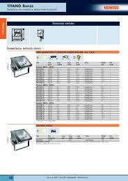
<strong>v<strong>ac</strong>on</strong> <strong>nxl</strong> mf4-mf6, ip21<br />
<strong>v<strong>ac</strong>on</strong> <strong>nxl</strong> mf4-mf6, ip54<br />
2
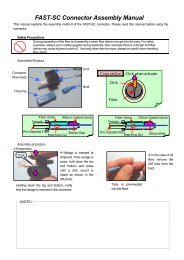
design & dimensions<br />
The mechanical design is extremely comp<strong>ac</strong>t. The IP54 units in particular are <strong>the</strong> smallest AC<br />
<strong>drive</strong>s on <strong>the</strong> market. All units are suitable for both wall <strong>and</strong> enclosure mounting with all necessary<br />
components: integrated EMC filters, AC chokes, cable protection, dust <strong>and</strong> water protection. The<br />
effective super-cooling principle allows high ambient temperatures <strong>and</strong> high switching frequencies<br />
without derating.<br />
Motor nominal values<br />
V<strong>ac</strong>on NXL features<br />
Voltage<br />
U (V)<br />
Power<br />
High overload<br />
P H (kW)<br />
Power<br />
Low overload<br />
P L (kW)<br />
Supply<br />
voltage<br />
U (V)<br />
EMC<br />
Enclosure<br />
Dimensions<br />
W x H x D (mm)<br />
Weight<br />
(kg)<br />
Integrated<br />
brake chopper<br />
Integrated<br />
AC choke<br />
Mechanical<br />
frame size<br />
400 0.75...4 1.1...5.5 380...500 H/T, C IP21/IP54 128 x 292 x 190 5 st<strong>and</strong>ard st<strong>and</strong>ard MF4<br />
500 1.1...5.5 1.5...7.5 380...500 H/T, C IP21/IP54 128 x 292 x 190 5 st<strong>and</strong>ard st<strong>and</strong>ard MF4<br />
400 5.5...11 7.5...15 380...500 H/T, C IP21/IP54 144 x 391 x 214 8.1 st<strong>and</strong>ard st<strong>and</strong>ard MF5<br />
500 7.5...15 11...18.5 380...500 H/T, C IP21/IP54 144 x 391 x 214 8.1 st<strong>and</strong>ard st<strong>and</strong>ard MF5<br />
400 15...22 18.5...30 380...500 H/T, C IP21/IP54 195 x 519 x 237 18.5 st<strong>and</strong>ard st<strong>and</strong>ard MF6<br />
500 18.5...30 22...37 380...500 H/T, C IP21/IP54 195 x 519 x 237 18.5 st<strong>and</strong>ard st<strong>and</strong>ard MF6<br />
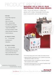
High voltage separated<br />
from control unit<br />
Temperature-controlled cooling<br />
fan, easily repl<strong>ac</strong>ed<br />
Cooling channel isolated<br />
from electronics<br />
Separate control unit<br />
Removable display panel<br />
Robust structure<br />
St<strong>and</strong>ard control I/O<br />
Integrated EMC filters<br />
as st<strong>and</strong>ard for both<br />
industrial <strong>and</strong> residential<br />
networks<br />
Option boards<br />
Integrated AC choke as st<strong>and</strong>ard<br />
Modular design to fulfill all EMC<br />
regulations (Faraday cage)<br />
3
mf4-mf6 product range<br />
Mains voltage 380—500 V, 50/60 Hz, 3~, enclosure class IP21/IP54, EMC level H<br />
Loadability<br />
Motor shaft power<br />
Low High 400 V supply<br />
AC <strong>drive</strong> type *<br />
Rated<br />
continuous<br />
current<br />
I L (A)<br />
10%<br />
overload<br />
current<br />
(A)<br />
Rated<br />
continuous<br />
current<br />
I H (A)<br />
50%<br />
overload<br />
current<br />
(A)<br />
Maximum 10%<br />
current I S overload<br />
40°C<br />
P (kW)<br />
50%<br />
overload<br />
50°C<br />
P (kW)<br />
Frame size<br />
NXL<br />
NXL<br />
NXL<br />
NXL<br />
NXL<br />
NXL<br />
0003<br />
0004<br />
0005<br />
0007<br />
0009<br />
0012<br />
5 C 2 H 1<br />
5 C 2 H 1<br />
5 C 2 H 1<br />
5 C 2 H 1<br />
5 C 2 H 1<br />
5 C 2 H 1<br />
3.3<br />
4.3<br />
5.6<br />
7.6<br />
9<br />
12<br />
3.6<br />
4.7<br />
6.2<br />
8.4<br />
9.9<br />
13.2<br />
2.2<br />
3.3<br />
4.3<br />
5.6<br />
7.6<br />
9<br />
3.3<br />
5.0<br />
6.5<br />
8.4<br />
11.4<br />
13.5<br />
4.4<br />
6.2<br />
8.6<br />
10.8<br />
14<br />
18<br />
1.1<br />
1.5<br />
2.2<br />
3<br />
4<br />
5.5<br />
0.75<br />
1.1<br />
1.5<br />
2.2<br />
3<br />
4<br />
MF4<br />
MF4<br />
MF4<br />
MF4<br />
MF4<br />
MF4<br />
NXL<br />
NXL<br />
NXL<br />
0016<br />
0023<br />
0031<br />
5 C 2 H 1<br />
5 C 2 H 1<br />
5 C 2 H 1<br />
16<br />
23<br />
31<br />
17.6<br />
25.3<br />
34<br />
12<br />
16<br />
23<br />
18.0<br />
24.0<br />
35<br />
24<br />
32<br />
46<br />
7.5<br />
11<br />
15<br />
5,5<br />
7,5<br />
11<br />
MF5<br />
MF5<br />
MF5<br />
NXL<br />
NXL<br />
NXL<br />
0038<br />
0046<br />
0061<br />
5 C 2 H 1<br />
5 C 2 H 1<br />
5 C 2 H 1<br />
38<br />
46<br />
61<br />
42<br />
51<br />
67<br />
31<br />
38<br />
46<br />
47<br />
57<br />
69<br />
62<br />
76<br />
92<br />
18.5<br />
22<br />
30<br />
15<br />
18.5<br />
22<br />
MF6<br />
MF6<br />
MF6<br />
* Type code of <strong>the</strong> IP21 unit. The type code of <strong>the</strong> IP54 unit: repl<strong>ac</strong>e ‘2’ with ‘5’; for example, NXL 0003 5C5H1<br />
For all V<strong>ac</strong>on NXL <strong>drive</strong>s, overloadability is defined as follows:<br />
High: 1.5 x I H (1 min/10 min) at 50°C; Low: 1.1 x I L (1 min/10 min) at 40°C; I S for 2 seconds every 20 seconds.<br />
<strong>v<strong>ac</strong>on</strong> <strong>nxl</strong> mf4–mf6 type designation code<br />
NXL 0007 5 C 2 H 1 SSS 00 AI<br />
F<strong>ac</strong>tory installed I/O exp<strong>and</strong>er boards <strong>and</strong> fieldbus boards (slot E)<br />
00 = no board<br />
AI = I/O extension board (3xDI, 1xRO, 1xTherm)<br />
AA = I/O extension board (3xDI, 1xRO, 1xDO)<br />
C3 = Profibus DP<br />
- More boards, see page 6<br />
F<strong>ac</strong>tory installed fieldbus boards (slot D)<br />
00 = no board<br />
C3 = Profibus DP<br />
- More boards, see page 6<br />
Hardware modifications (power unit, special modifications, board varnishing)<br />
SSS = st<strong>and</strong>ard<br />
SSV = varnished boards<br />
STS = flange mounting<br />
Brake chopper option<br />
1 = internal brake chopper (st<strong>and</strong>ard)<br />
Emission level<br />
H = fulfills <strong>the</strong> st<strong>and</strong>ard EN 61800-3 (2004), category C2<br />
C = fulfills <strong>the</strong> st<strong>and</strong>ard EN 61800-3 (2004), category C1<br />
T = Low earth-current solution for IT networks (can be modified from H level units)<br />
Enclosure classification<br />
2 = IP21<br />
5 = IP54<br />
Control keypad<br />
C = 7-segment LCD keypad<br />
B = no keypad<br />
Nominal mains voltage<br />
5 = 380…500 V AC (3-phase)<br />
Nominal current (Low overload)<br />
e.g. 0007 = 7 Amps<br />
Product range<br />
V<strong>ac</strong>on NXL<br />
4
comp<strong>ac</strong>t yet so powerful<br />
The V<strong>ac</strong>on NXL range also offers comp<strong>ac</strong>t, cabinet-mounted units for lower motor powers. Frames<br />
MF2 <strong>and</strong> MF3 are suitable for both 208–230 V <strong>and</strong> 380–500 V supply voltages for powers up to 2.2<br />
kW. The comp<strong>ac</strong>t size <strong>and</strong> flexible installation options make <strong>the</strong> V<strong>ac</strong>on NXL suitable for installations<br />
where sp<strong>ac</strong>e is at a premium. The st<strong>and</strong>ard control I/O can be extended with one I/O exp<strong>and</strong>er<br />
board or one fieldbus board.<br />
Features<br />
• Small size<br />
• Flexible installation (b<strong>ac</strong>k or side, screw or DIN rail)<br />
• Easy to install <strong>and</strong> use<br />
• Low noise<br />
• Large amount of control possibilities (via I/Os,<br />
fieldbuses or display panel)<br />
• Large amount of features (e.g. fully programmable<br />
I/O, auto-identification, PID controller, flying start)<br />
• High performance<br />
• RFI filters <strong>and</strong> AC chokes available as options<br />
Mains voltage 380—500 V, 50/60 Hz, 3~, enclosure class IP20, EMC level N<br />
Loadability<br />
Motor shaft power<br />
Low High 400 V supply<br />
AC <strong>drive</strong> type<br />
Rated<br />
continuous<br />
current<br />
I L (A)<br />
10%<br />
overload<br />
current<br />
(A)<br />
Rated<br />
continuous<br />
current<br />
I H (A)<br />
50%<br />
overload<br />
current<br />
(A)<br />
Maximum 10%<br />
current I S overload<br />
40°C<br />
P (kW)<br />
50%<br />
overload<br />
50°C<br />
P (kW)<br />
Frame size <strong>and</strong><br />
dimensions<br />
(W x H x D)<br />
NXL 0001 5 C 1 N 0 1.9 2.1 1.3 2.0 2.6 0.55 0.37 MF2 / 60 x 130 x 150<br />
NXL 0002 5 C 1 N 0 2.4 2.6 1.9 2.9 3.8 0.75 0.55 MF2 / 60 x 130 x 150<br />
NXL 0003 5 C 1 N 1 3.3 3.6 2.4 3.6 4.8 1.1 0.75 MF3 / 84 x 220 x 172<br />
NXL 0004 5 C 1 N 1 4.3 4.7 3.3 5.0 6.6 1.5 1.1 MF3 / 84 x 220 x 172<br />
NXL 0005 5 C 1 N 1 5.4 5.9 4.3 6.5 8.6 2.2 1.5 MF3 / 84 x 220 x 172<br />
Mains voltage 208—240 V, 50/60 Hz, 1/3~ (3~ motor), enclosure class IP20, EMC level N<br />
Loadability<br />
Motor shaft power<br />
Low High 230 V supply<br />
AC <strong>drive</strong> type<br />
Rated<br />
continuous<br />
current<br />
I L (A)<br />
10%<br />
overload<br />
current<br />
(A)<br />
Rated<br />
continuous<br />
current<br />
I H (A)<br />
50%<br />
overload<br />
current<br />
(A)<br />
Maximum 10%<br />
current I S overload<br />
40°C<br />
P (kW)<br />
50%<br />
overload<br />
50°C<br />
P (kW)<br />
Frame size <strong>and</strong><br />
dimensions<br />
(W x H x D)<br />
NXL 0002 2 C 1 N 0* 2.4 2.6 1.7 2.6 3.4 0.37 0.25 MF2 / 60 x 130 x 150<br />
NXL 0003 2 C 1 N 1 3.7 4.1 2.8 4.2 5.6 0.75 0.55 MF3 / 84 x 220 x 172<br />
NXL 0004 2 C 1 N 1 4.8 5.3 3.7 5.6 7.4 1.1 0.75 MF3 / 84 x 220 x 172<br />
NXL 0006 2 C 1 N 1 6.6 7.2 4.8 7.2 9.6 1.5 1.1 MF3 / 84 x 220 x 172<br />
* suitable only for single-phase supply voltage (<strong>the</strong> rest suitable for both single-phase <strong>and</strong> three-phase supply voltages)<br />
5
<strong>v<strong>ac</strong>on</strong> <strong>nxl</strong> control unit<br />
I/O exp<strong>and</strong>er boards,<br />
fieldbus boards<br />
The st<strong>and</strong>ard I/O of <strong>the</strong> V<strong>ac</strong>on NXL has been optimized for typical<br />
control requirements. In addition to digital <strong>and</strong> analog inputs<br />
<strong>and</strong> outputs, RS485 (Modbus RTU) is included as st<strong>and</strong>ard.<br />
All inputs <strong>and</strong> outputs of <strong>the</strong> st<strong>and</strong>ard I/O <strong>and</strong> option boards are<br />
freely programmable. Both Analog Inputs can be programmed<br />
for 0...10 V or 0(4)...20 mA signals. Analog Input can also be programmed<br />
as Digital Input.<br />
St<strong>and</strong>ard I/O<br />
The st<strong>and</strong>ard I/O can easily <strong>and</strong> cost-effectively be extended<br />
with OPT-AA or OPT-AI boards, if necessary. The OPT-AA is <strong>the</strong><br />
most effective way to add one more Relay Output, <strong>and</strong> <strong>the</strong> OPT-<br />
AI is normally used when galvanically isolated motor <strong>the</strong>rmistor<br />
connection is needed. These boards are installed in option<br />
board slot E.<br />
It is also possible to control <strong>the</strong> V<strong>ac</strong>on NXL with various kinds of<br />
fieldbuses with OPT-C-type boards (see <strong>the</strong> table below). The<br />
I/O extension <strong>and</strong> fieldbus boards are <strong>the</strong> same for all V<strong>ac</strong>on NX<br />
products. The fieldbus boards can be installed in slot D or E.<br />
There are a large number of OPT-B-type option boards available.<br />
The most typical boards are included in <strong>the</strong> table below. It<br />
is possible, for instance, to add three more output relays with<br />
OPT-B5, if necessary. The OPT-B-type boards are typically installed<br />
in slot E.<br />
<strong>v<strong>ac</strong>on</strong> <strong>nxl</strong> option boards<br />
Card typecode Slot I/O signal<br />
D E DI DO AI<br />
mA<br />
isol.<br />
AO<br />
mA<br />
isol.<br />
RO<br />
NO<br />
NC<br />
RO<br />
NO<br />
Therm +24<br />
EXT<br />
+24V<br />
NOTE<br />
Basic I/O cards (OPT-A)<br />
OPT-AA 3 1 1<br />
OPT-AI 3 1 1<br />
I/O exp<strong>and</strong>er cards (OPT-B), typical<br />
OPT-B2 1 1 1<br />
OPT-B4 1 2 1 analog signals galvanically isolated separately<br />
OPT-B5 3<br />
Fieldbus cards (OPT-C)<br />
OPT-C2 RS-485 (Multiprotocol) N2 (Modbus as st<strong>and</strong>ard)<br />
OPT-C3<br />
OPT-C4<br />
OPT-C5<br />
OPT-C6<br />
OPT-C7<br />
Profibus DP<br />
LonWorks<br />
Profibus DP (D9 type connector)<br />
CANopen (slave)<br />
DeviceNet<br />
OPT-C8 RS-485 (Multiprotocol, D9 type connector) N2 (Modbus as st<strong>and</strong>ard)<br />
OPT-CI<br />
OPT-CJ<br />
Modbus/TCP (E<strong>the</strong>rnet)<br />
BACnet<br />
NOTES: Allowed slots for <strong>the</strong> board are marked in blue. Allowed option board combinations are as follows:<br />
no boards, 1xOPT-Ax, 1xOPT-Bx, 1xOPT-Cx, or 1xOPT-Ax <strong>and</strong> 1xOPT-Cx.<br />
6
<strong>v<strong>ac</strong>on</strong> <strong>nxl</strong> control i/o<br />
St<strong>and</strong>ard I/O<br />
OPT-AA (typical option)<br />
Terminal<br />
Signal, default settings<br />
Terminal<br />
Signal, default settings<br />
1...10 kΩ<br />
mA<br />
1 +10V Reference voltage<br />
2 AI1+ Analog input, 0–10 V (0/4–20 mA)<br />
3 AI1- AI common<br />
4 AI2+ Analog input, 0/4–20 mA (0–10 V)<br />
5 AI2- AI common<br />
6 +24V 24V auxiliary voltage<br />
7 GND I/O ground<br />
8 DIN1 Start forward<br />
9 DIN2 Start reverse<br />
10 DIN3 Preset speed 1<br />
11 GND I/O ground<br />
18 AO1+ Analog output, output frequency<br />
19 AO1- AO common<br />
A RS485 Serial bus (Modbus RTU)<br />
B RS485 Serial bus<br />
30 +24V External control voltage supply<br />
21 RO1 Relay output 1, FAULT<br />
22 RO1<br />
23 RO1<br />
All inputs <strong>and</strong> outputs of <strong>the</strong> st<strong>and</strong>ard I/O <strong>and</strong> option boards are<br />
freely programmable.<br />
1 +24V 24 V auxiliary voltage<br />
2 GND I/O ground<br />
3 DIN1 Preset speed 2<br />
4 DIN2 Fault reset<br />
5 DIN3 Disable PID<br />
6 DO1 Digital output, Ready<br />
24 RO1 Relay output 1, RUN<br />
25 RO1<br />
26 RO1<br />
OPT-AI (typical option)<br />
Terminal Signal, default settings<br />
12 +24V 24 V auxiliary voltage<br />
13 GND I/O ground<br />
14 DIN1 Preset speed 2<br />
15 DIN2 Fault reset<br />
16 DIN3 Disable PID<br />
25 RO1 Relay output 1, RUN<br />
26 RO1<br />
28 TI1+ Thermistor input<br />
29 TI1- (galvanically isolated)<br />
o<strong>the</strong>r typical options<br />
OPTION ORDER TYPECODE SUITABILITY NOTE<br />
IP54 enclosure F<strong>ac</strong>tory option MF4-MF6 Repl<strong>ac</strong>e ‘2’ by ‘5’ in <strong>the</strong> type code, e.g. NXL00315C5H1 (SSS...)<br />
IP5-FR_ MF4-MF6 IP54 kit, e.g. IP5-FR4<br />
Through-hole mounting F<strong>ac</strong>tory option MF4-MF6 E.g. NXL00315CTH1STS..., IP54 b<strong>ac</strong>k, IP21 front, kits available<br />
External brake resistors BRR-0022-LD-5 00035-00225 LD = Light Duty: 5 sec nominal torque braking from<br />
BRR-0031-LD-5 00315<br />
nominal speed decreasing linearily to zero, once per 120 sec.<br />
HD = Heavy Duty: 3 sec nominal torque braking at<br />
BRR-0045-LD-5 00385-00465 nominal speed + 7 sec nominal torque braking from nominal<br />
BRR-0061-LD-5 00615<br />
speed decreasing linearily to zero, once per 120 sec.<br />
Repl<strong>ac</strong>e LD by HD in <strong>the</strong> type code, e.g. BRR-0031-HD-5<br />
The brake resistor manual is available for more precise selection<br />
Panel door installation sets<br />
DRA-02L<br />
DRA-04L<br />
All<br />
Door installation set with a 2-m RS232C cable<br />
Door installation set with a 4-m RS232C cable<br />
PC adapter PAN-RS All Adapter PAN-RS <strong>and</strong> a RS232C cable are required for PC connection<br />
RS232C cables<br />
RS232C-2M<br />
RS232C-4M<br />
All<br />
2-meter-long RS232C cable for PC connection<br />
4-meter-long RS232C cable for PC connection<br />
Varnished circuit boards F<strong>ac</strong>tory option MF4-MF6 Repl<strong>ac</strong>e <strong>the</strong> ‘S’ by ‘V’, e.g. NXL00315C5H1SSV...<br />
C-level RFI filters F<strong>ac</strong>tory option MF4-MF6 Repl<strong>ac</strong>e ‘H’ by ‘C’ in <strong>the</strong> typecode, e.g. NXL00315C2C1 (SSS...)<br />
OPTIONS FOR COMPACT UNITS (MF2-MF3)<br />
RFI filters RFI-0012-2-1 00022-00062 RFI filter for 208-230 V units, H level, 1~ supply<br />
RFI-0013-2-1 00022-00062 RFI filter for 208-230 V units, H level, 1~ supply, footprint installation<br />
RFI-0008-5-1 00015-00055 RFI filter for 380-500 V units, H level, footprint installation<br />
DIN rail installation F<strong>ac</strong>tory option MF2-MF3 Repl<strong>ac</strong>e ‘S’ by ‘D’ in <strong>the</strong> typecode, e.g. NXL 00025C1HO SDS<br />
7
first-class usability<br />
The basic settings can be programmed by simply launching <strong>the</strong> V<strong>ac</strong>on NXL start-up wizard.<br />
Only four steps are required, <strong>and</strong> <strong>the</strong> <strong>drive</strong> is ready to run.<br />
START-UP WIZARD<br />
=Push <strong>the</strong> button<br />
START MODE rpm n I n (A)<br />
+<br />
rpm<br />
A<br />
+<br />
+<br />
-<br />
+<br />
+<br />
-<br />
ENTER<br />
reset<br />
-<br />
ENTER<br />
reset<br />
-<br />
ENTER<br />
reset<br />
-<br />
ENTER<br />
reset<br />
1 Push 5 seconds 2 Select <strong>the</strong> 3 Accept<br />
4 Tune 5 Accept<br />
6 Tune Accept<br />
to <strong>ac</strong>tivate (in<br />
mode. See<br />
n(rpm)<br />
7<br />
I(A)<br />
stop mode)<br />
table below!<br />
P2.1.1Min. Freq (Hz)<br />
P2.1..2 Max.Freq (Hz)<br />
P2.1.3 Acc time (s)<br />
P2.1.4 Dec time (s)<br />
P2.1.5 Current limit(A)<br />
P2.1.6 Motor Un (V)<br />
P2.1.7 Motor fn(Hz)<br />
P2.1.11Start funct.<br />
P2.1.12 Stop funct.<br />
P2.1.13 U/f optimization<br />
P2.1.14 I/0 ref<br />
P2.1.21 Auto restart<br />
P3.1 Control pl<strong>ac</strong>e<br />
M<br />
St<strong>and</strong>ard<br />
Fan<br />
Pump<br />
0<br />
Hz<br />
20<br />
Hz<br />
20<br />
Hz<br />
0<br />
Hz<br />
High<br />
performance<br />
50<br />
Hz<br />
50<br />
Hz<br />
50<br />
Hz<br />
50<br />
Hz<br />
3<br />
s<br />
20<br />
s<br />
5<br />
s<br />
1<br />
s<br />
3<br />
s<br />
20<br />
s<br />
5<br />
s<br />
1<br />
s<br />
I *1,5 400<br />
H<br />
V<br />
I *1,1 400<br />
L<br />
V<br />
I *1,1 400<br />
L<br />
V<br />
I *1,8 400<br />
H<br />
V<br />
50<br />
Hz<br />
50<br />
Hz<br />
50<br />
Hz<br />
50<br />
Hz<br />
0= 0=<br />
Ramp Coasting<br />
0= 0=<br />
Ramp Coasting<br />
0=<br />
Ramp<br />
1=<br />
Ramp<br />
0= 0=<br />
Ramp Coasting<br />
0=<br />
Not<br />
used<br />
0=<br />
Not<br />
used<br />
0=<br />
Not<br />
used<br />
1=<br />
automatic<br />
torque<br />
boost<br />
0=<br />
Ai1<br />
0-10V<br />
0=<br />
Ai1<br />
0-10V<br />
0=<br />
Ai1<br />
0-10V<br />
0=<br />
Ai1<br />
0-10V<br />
0=<br />
Not<br />
used<br />
0=<br />
Not<br />
used<br />
0=<br />
Not<br />
used<br />
0=<br />
Not<br />
used<br />
I/O<br />
I/O<br />
I/O<br />
I/O<br />
For example: These settings are made automatically<br />
if <strong>the</strong> fan mode is selected.<br />
The instructions to install, connect <strong>and</strong> program <strong>the</strong> V<strong>ac</strong>on<br />
NXL are included in <strong>the</strong> credit-card size Quick Guide att<strong>ac</strong>hed<br />
to e<strong>ac</strong>h unit.<br />
8
multi-control application<br />
The st<strong>and</strong>ard Multi-Control Application software of <strong>the</strong> V<strong>ac</strong>on NXL is extremely flexible <strong>and</strong> <strong>easy</strong> to<br />
use. All inputs <strong>and</strong> outputs are programmable, <strong>and</strong> <strong>the</strong>re is a full set of features <strong>and</strong> possibilities<br />
for system or process control <strong>and</strong> protections.<br />
The default settings are very close to optimum, <strong>and</strong> <strong>the</strong><br />
<strong>drive</strong> operates <strong>ac</strong>curately enough without any programming.<br />
It still is recommended to check <strong>and</strong> fine-tune <strong>the</strong><br />
motor nominal values to optimize <strong>the</strong> performance <strong>and</strong><br />
motor protection. Programming can be made simply by<br />
using <strong>the</strong> start-up wizard feature of <strong>the</strong> display panel, programming<br />
parameter by parameter with display panel, or<br />
programming by <strong>the</strong> NCDrive tool. The instructions, if required,<br />
can be found in <strong>the</strong> credit-card-size Quick Guide.<br />
The V<strong>ac</strong>on PC tools are available for downloading from <strong>the</strong><br />
V<strong>ac</strong>on website at http://www.<strong>v<strong>ac</strong>on</strong>.com. These include:<br />
• V<strong>ac</strong>on NCDrive for parameter setting, copying, storing,<br />
printing, monitoring <strong>and</strong> controlling<br />
• V<strong>ac</strong>on NCLoad for software updating <strong>and</strong> uploading<br />
special software to <strong>the</strong> <strong>drive</strong><br />
• V<strong>ac</strong>on NC61131-3 Engineering is available for making tailor-made<br />
software. (A license key <strong>and</strong> training required)<br />
There are many parameters <strong>and</strong> features which can be utilized,<br />
if necessary. For example:<br />
The following software applications are available for special<br />
requirements:<br />
• PID controller<br />
• Pump <strong>and</strong> fan control for a maximum of 4 parallel motors<br />
• Flying start<br />
• Auto-tuning<br />
• Programming of all control inputs <strong>and</strong> outputs<br />
• Output relay delays<br />
• Brake control<br />
• Lift<br />
• Multi-motor<br />
• Sliding door<br />
• Local/remote<br />
• Fire mode<br />
• Multi-purpose<br />
In addition to <strong>the</strong> st<strong>and</strong>ard MultiControl Application software,<br />
some special application software is also available.<br />
It is even possible to make totally customer-specific software<br />
with <strong>the</strong> NC61131-3 Engineering tool, <strong>and</strong> remove <strong>the</strong><br />
PLC by integrating <strong>the</strong> logic to <strong>the</strong> NXL software.<br />
Exp<strong>and</strong>er board menu<br />
System menu<br />
Fault history menu<br />
+<br />
- ENTER<br />
reset<br />
Active faults menu<br />
Keypad control menu<br />
Parameter menu<br />
Navigation <strong>and</strong><br />
selection keys<br />
Monitoring menu<br />
Navigating <strong>the</strong> menu structure (e.g. special parameters,<br />
monitoring signals)<br />
Activating <strong>the</strong> start-up wizard<br />
9
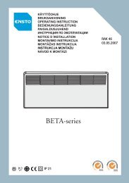
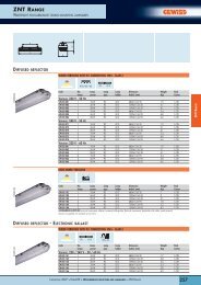
emc <strong>and</strong> installation environment<br />
1ST ENVIRONMENT<br />
3<br />
2<br />
1<br />
2<br />
4<br />
5<br />
2ND ENVIRONMENT<br />
The product family st<strong>and</strong>ard EN61800-3 sets limits for both<br />
emissions <strong>and</strong> immunity of radio frequency disturbances. The<br />
environment has been divided into <strong>the</strong> 1st <strong>and</strong> 2nd environments,<br />
which, in pr<strong>ac</strong>tice, means public <strong>and</strong> industrial networks.<br />
Radio Frequency Interference (RFI) filters are typically required<br />
to meet <strong>the</strong> EN61800-3 st<strong>and</strong>ard. These filters are integrated<br />
in <strong>the</strong> V<strong>ac</strong>on NXL MF4-MF6 as st<strong>and</strong>ard.<br />
The V<strong>ac</strong>on NXL fulfills all <strong>the</strong> requirements of <strong>the</strong> 1st <strong>and</strong><br />
2nd environments (H level: EN61800-3 (2004), category C2).<br />
No additional RFI filters or cabinets are required for frames<br />
MF4-MF6.<br />
The V<strong>ac</strong>on NXL MF4-MF6 units are also available with extremely<br />
low-emission integrated EMC filters (C level:<br />
EN61800-3 (2004), category C1; EN55011, class B). These filters<br />
are sometimes required in very sensitive locations such<br />
as hospitals.<br />
EMC Selection Table, restricted distribution<br />
1 2 3 4 5<br />
V<strong>ac</strong>on NXL EMC Hospital Residential Area Commercial Light Industry Area Heavy Industry Marine<br />
C<br />
O<br />
H R R R O O<br />
L R R<br />
T R (IT Network) R (IT Network)<br />
R = Required ; O = Optional<br />
10
technical data<br />
Mains<br />
connection<br />
Motor<br />
connection<br />
Control<br />
char<strong>ac</strong>teristics<br />
Input voltage U in 380…500 V, –10%…+10%, 208...240 V, -10%...+10%<br />
Input frequency<br />
45…66 Hz<br />
Connection to mains<br />
Once per minute or less (normal case)<br />
Output voltage<br />
0...U in<br />
Continuous output current<br />
High overloadability: I H , ambient temperature max. +50°C<br />
Low overloadability: I L , ambient temperature max. +40°C<br />
Overloadability<br />
High: 1.5 x I H (1 min/10 min), Low: 1.1 x I L (1 min/10 min)<br />
Max. starting current<br />
I s for 2 s every 20 s<br />
Output frequency<br />
0…320 Hz<br />
Frequency resolution<br />
0.01 Hz<br />
Control method<br />
Frequency control U/f; Open Loop Vector Control<br />
Switching frequency<br />
1…16 kHz; F<strong>ac</strong>tory default 6 kHz, (MF2, MF3: default 3,6 kHz)<br />
Field weakening point<br />
8…320 Hz<br />
Acceleration time<br />
0…3000 s<br />
Deceleration time<br />
0…3000 s<br />
Braking<br />
DC brake: 30% * T N (without brake resistor), flux braking<br />
Ambient conditions Ambient operating temperature –10°C (no frost)…+50°C: I H<br />
–10°C (no frost)…+40°C: I L<br />
Storage temperature<br />
–40°C…+70°C<br />
Relative humidity<br />
Air quality:<br />
- chemical vapours<br />
- mechanical particles<br />
Altitude<br />
Vibration<br />
EN50178/EN60068-2-6<br />
Shock<br />
EN50178, EN60068-2-27<br />
Enclosure class<br />
EMC Immunity Fulfills all EMC immunity requirements<br />
Emissions<br />
0 to 95% RH, non-condensing, non-corrosive, no dripping water<br />
IEC 721-3-3, unit in operation, class 3C2<br />
IEC 721-3-3, unit in operation, class 3S2<br />
100% load cap<strong>ac</strong>ity (no derating) up to 1000 m<br />
1% derating for e<strong>ac</strong>h 100 m above 1000 m; max. 3000 m<br />
5...150 Hz<br />
Displ<strong>ac</strong>ement amplitude 1 mm (peak) at 3…15.8 Hz<br />
Max <strong>ac</strong>celeration amplitude 1 G at 15.8…150 Hz<br />
UPS Drop Test (for applicable UPS weights)<br />
Storage <strong>and</strong> shipping: max 15 G, 11 ms (in p<strong>ac</strong>kage)<br />
MF4-MF6: IP21 <strong>and</strong> IP54; MF2-MF3: IP20<br />
MF4-MF6:<br />
EMC level H: EN61800-3 (2004), category C2; EN61000-6-4, EN50081-2; EN55011 class A<br />
EMC level C: EN61800-3 (2004), category C1; EN61000-6-3, EN50081-1,-2; EN55011 class B<br />
EMC level T: Low earth-current solution suitable for IT networks (can be modified from H-level units)<br />
MF2-MF3:<br />
EMC level N: EN61800-3 (2004), category C4<br />
EMC level H w/ RFI filter: EN61800-3 (2004), category C2; EN61000-6-4, EN50081-2; EN55011 class A.<br />
Safety<br />
Control<br />
connections<br />
(values in br<strong>ac</strong>kets<br />
valid for OPT-AA or<br />
OPT-AI)<br />
Protections<br />
EN 50178 (1997), EN 60204-1 (1996), EN 60950 (2000, 3rd edition) (as relevant),<br />
IEC 61800-5, CE, UL, CUL; (see unit nameplate for more detailed approvals)<br />
Analogue input voltage 0…+10 V, R i = 200 kΩ, resolution 0.1%, <strong>ac</strong>cur<strong>ac</strong>y ±1%<br />
Analogue input current 0(4)…20 mA, R i = 250 Ω differential, resolution 0.1%, <strong>ac</strong>cur<strong>ac</strong>y ±1%<br />
Digital inputs<br />
3 (6), 18…30 VDC<br />
Auxiliary voltage<br />
+24 V, ±15 %, max. 250mA (MF2-MF3: 100mA)<br />
Output reference voltage +10 V, +3%, max. load 10 mA<br />
Analogue output 0(4)…20 mA; R L max. 500 Ω, resolution 10 bit, <strong>ac</strong>cur<strong>ac</strong>y ±2%<br />
Relay outputs<br />
1 (2) programmable relay output(s)<br />
Switching cap<strong>ac</strong>ity: 24 VDC/8 A, 250 VAC/8 A, 125 VDC/0.4 A. Min. switching load: 5 V/10 mA<br />
RS-485<br />
Serial bus (Modbus RTU)<br />
Thermistor input<br />
Galvanically isolated, R trip = 4.7 kΩ (OPT-AI)<br />
Overvoltage, undervoltage, earth fault, motor phase supervision, overcurrent, unit overtemperature,<br />
motor overload, motor stall, motor underload, short-circuit of +24 V <strong>and</strong> +10 V reference voltages<br />
11
www.<strong>v<strong>ac</strong>on</strong>.com<br />
V<strong>ac</strong>on Partner<br />
Subject to changes without notice.<br />
12<br />
BC00089D