
Create successful ePaper yourself
Turn your PDF publications into a flip-book with our unique Google optimized e-Paper software.
<strong>Relays</strong> & Sockets<br />
<strong>RY</strong>/<strong>RM</strong> <strong>Series</strong><br />
<strong>RY</strong>/<strong>RM</strong> <strong>Series</strong> <strong>Miniature</strong> <strong>Relays</strong><br />
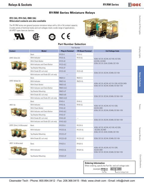
<strong>RY</strong>2 (3A), <strong>RY</strong>4 (5A), <strong>RM</strong>2 (5A)<br />
Bifurcated contacts are also available<br />
The <strong>RY</strong>/<strong>RM</strong> series are general purpose miniature relays with a 3A or 5A contact capacity.<br />
A wide variety of terminal styles and coil voltages meet a wide range of applications.<br />
All 4PDT types have arc barriers.<br />
Part Number Selection<br />
Part Number<br />
Contact Model Plug-in Terminal PC Board Terminal Coil Voltage Code<br />
DPDT (Slim) 3A<br />
DPDT (Wide) 5A<br />
4PDT 5A<br />
Basic <strong>RY</strong>2S-U <strong>RY</strong>2V-U<br />
With Indicator <strong>RY</strong>2S-UL <strong>RY</strong>2V-UL<br />
With Check Button<br />
With Indicator and Check Button<br />
Top Bracket Mounting<br />
<strong>RY</strong>2S-UC<br />
<strong>RY</strong>2S-ULC<br />
<strong>RY</strong>2S-UT<br />
With Diode (DC coil only) <strong>RY</strong>2S-UD <strong>RY</strong>2V-UD<br />
With Indicator and Diode (DC coil only) —<br />
Basic <strong>RM</strong>2S-U <strong>RM</strong>2V-U<br />
With Indicator <strong>RM</strong>2S-UL <strong>RM</strong>2V-UL<br />
With Check Button<br />
<strong>RM</strong>2S-UC<br />
With Indicator and Check Button <strong>RM</strong>2S-ULC<br />
Top Bracket Mounting<br />
<strong>RM</strong>2S-UT<br />
With Diode (DC coil only)<br />
<strong>RM</strong>2S-UD<br />
With Indicator and Diode (DC coil only) <strong>RM</strong>2S-ULD<br />
Basic <strong>RY</strong>4S-U <strong>RY</strong>4V-U<br />
With Indicator <strong>RY</strong>4S-UL <strong>RY</strong>4V-UL<br />
With Check Button<br />
<strong>RY</strong>4S-UC<br />
With Indicator and Check Button <strong>RY</strong>4S-ULC<br />
Top Bracket Mounting<br />
<strong>RY</strong>4S-UT<br />
With Diode (DC coil only) <strong>RY</strong>4S-UD —<br />
With Indicator and Diode (DC coil only)<br />
<strong>RY</strong>4S-ULD<br />
DPDT (Slim) 1A Bifurcated Basic <strong>RY</strong>22S-U <strong>RY</strong>22V-U<br />
With Indicator <strong>RY</strong>22S-UL <strong>RY</strong>22V-UL<br />
Top Bracket Mounting<br />
<strong>RY</strong>22S-UT<br />
AC6V, AC12V, AC24V, AC110V, AC120V,<br />
AC220V, AC240V<br />
DC6V, DC12V, D24V, DC48V, DC110V<br />
DC6V, DC12V, DC24V, DC48V, DC110V<br />
AC6V, AC12V, AC24V, AC110-120V, AC220-240V<br />
DC6V, DC12V, DC24V, DC48V, DC100-110V<br />
DC6V, DC12V, DC24V, DC48V, DC100-110V<br />
AC6V, AC12V, AC24V, AC110-120V,<br />
AC220-240V<br />
DC6V, DC12V, DC24V, DC48V, DC100-110V<br />
DC6V, DC12V, DC24V, DC48V, DC100-110V<br />
AC6V, AC12V, AC24V, AC110V, AC120V,<br />
AC220V, AC240V<br />
DC6V, DC12V, D24V, DC48V, DC110V<br />
With Diode (DC coil only) <strong>RY</strong>22S-UD <strong>RY</strong>22V-UD DC6V, DC12V, DC24V, DC48V, DC110V<br />
4PDT 1A Bifurcated Basic <strong>RY</strong>42S-U <strong>RY</strong>42V-U<br />
With Indicator <strong>RY</strong>42S-UL <strong>RY</strong>42V-UL<br />
Top Bracket Mounting<br />
<strong>RY</strong>42S-UT<br />
AC6V, AC12V, AC24V, AC110-120V,<br />
AC220-240V<br />
DC6V, DC12V, DC24V, DC48V, DC100-110V<br />
Ordering Information<br />
When ordering, specify the Part No. and coil voltage code:<br />
(example) <strong>RY</strong>4S-U AC110-120V<br />
Part No.<br />
Coil Voltage Code<br />
Switches & Pilot Lights Display Lights <strong>Relays</strong> & Sockets Timers Terminal Blocks Circuit Breakers<br />
Clearwater Tech - Phone: 800.894.0412 USA: 800-262-<strong>IDEC</strong> - Fax: 208.368.0415 Canada: - 888-317-<strong>IDEC</strong> Web: www.clrwtr.com - Email: info@clrwtr.com763
<strong>Relays</strong> & Sockets<br />
Switches & Pilot Lights<br />
Sockets<br />
<strong>RY</strong>2S<br />
<strong>RY</strong>22S<br />
<strong>Relays</strong><br />
Standard DIN<br />
Rail Mount<br />
Finger-safe DIN<br />
Rail Mount<br />
Through Panel Mount<br />
SY2S-05 SY2S-05C SY2S-51 SY2S-61<br />
<strong>RM</strong>2 SM2S-05 SM2S-05C SM2S-51<br />
<strong>RY</strong>4S<br />
<strong>RY</strong>42S<br />
SY4S-05 SY4S-05C SY4S-51<br />
SY4S-61<br />
SY4S-62<br />
PCB Mount<br />
Display Lights<br />
Hold Down Springs & Clips<br />
Appearance Description Relay<br />
For DIN<br />
Mount Socket<br />
For Through Panel &<br />
PCB Mount Socket<br />
Min Order Qty<br />
<strong>RY</strong>2S<br />
<strong>RY</strong>22S<br />
SY2S-02F1<br />
SY4S-51F1<br />
<strong>Relays</strong> & Sockets<br />
Pullover Wire<br />
Spring<br />
Leaf Spring*<br />
(side latch)<br />
<strong>RM</strong>2<br />
<strong>RY</strong>4S<br />
<strong>RY</strong>42S<br />
<strong>RY</strong>2S, <strong>RY</strong>22S<br />
<strong>RM</strong>2, <strong>RY</strong>4S, <strong>RY</strong>42S<br />
SY4S-51F1<br />
SY4S-51F1<br />
SFA-202 SFA-302<br />
10<br />
Leaf Spring*<br />
(top latch)<br />
<strong>RY</strong>2S, <strong>RY</strong>22S<br />
<strong>RM</strong>2<br />
<strong>RY</strong>4S, <strong>RY</strong>42S<br />
SFA-101 SFA-301<br />
20<br />
Timers<br />
*Not available for PCB mount socket SY4S-62.<br />
Terminal Blocks<br />
Accessories<br />
Description Appearance Use with Part No. Remarks<br />
Aluminum<br />
DIN Rail<br />
(1 meter length)<br />
DIN Rail End<br />
Stop<br />
Replacement<br />
Hold-Down<br />
Spring Anchor<br />
All DIN rail sockets BNDN1000<br />
DIN rail BNL5 9.1 mm wide.<br />
Horseshoe clip for all DIN rail<br />
sockets<br />
Y778-011<br />
<strong>IDEC</strong> offers a low-profile DIN rail (BNDN1000). The BNDN1000 is designed<br />
to accommodate DIN mount sockets. Made of durable extruded<br />
aluminum, the BNDN1000 measures 0.413 (10.5mm) in height and 1.37<br />
(35mm) in width (DIN standard). Standard length is 39” (1,000mm).<br />
For use on DIN rail mount socket when using pullover wire hold down<br />
spring. 2 pieces included with each socket.<br />
Circuit Breakers<br />
Clearwater Tech - Phone: 800.894.0412 - Fax: 208.368.0415 - Web: www.clrwtr.com - Email: info@clrwtr.com
<strong>Relays</strong> & Sockets<br />
<strong>RY</strong>/<strong>RM</strong> <strong>Series</strong><br />
Specifications<br />
Contact Model<br />
Standard Contact<br />
Bifurcated Contact<br />
<strong>RY</strong>2 - DPDT Slim <strong>RM</strong>2 - DPDT Wide <strong>RY</strong>4 - 4PDT <strong>RY</strong>22 - DPDT / <strong>RY</strong>42 - 4PDT<br />
Contact Material Gold-plated silver Silver Gold-plated silver Silver-palladium alloy<br />
Contact Resistance 1 50 mΩ maximum 30 mΩ maximum 50 mΩ maximum 100 mΩ minimum<br />
Minimum Applicable Load<br />
Operate Time 2<br />
Release Time 2<br />
Power Consumption<br />
(approx.)<br />
Insulation Resistance<br />
Dielectric Strength 3<br />
24V DC, 5 mA; 5V DC,<br />
10 mA (reference value)<br />
AC: 1.1 VA (50 Hz), 1 VA (60 Hz)<br />
DC: 0.8W<br />
100 MΩ minimum (500V DC megger)<br />
24V DC, 10 mA; 5V DC,<br />
20 mA (reference value)<br />
AC: 1.4 VA (50 Hz), 1.2 VA (60 Hz)<br />
DC: 0.9W<br />
24V DC, 5 mA; 5V DC,<br />
10 mA (reference value)<br />
20 ms maximum<br />
20 ms maximum<br />
Between live and dead parts:<br />
AC: 1.4 VA (50 Hz), 1.2 VA (60 Hz)<br />
DC: 0.9W<br />
1V DC, 100 μA (reference value)<br />
AC: 1.1 VA (50 Hz), 1 VA (60 Hz)<br />
DC: 0.8W<br />
1500V AC, 1 minute 2000V AC, 1 minute 2000V AC, 1 minute 1500V AC, 1 minute 3<br />
Between contact and coil:<br />
1500V AC, 1 minute 2000V AC, 1 minute 2000V AC, 1 minute 1500V AC, 1 minute<br />
Between contacts of different poles:<br />
1500V AC, 1 minute 2000V AC, 1 minute 2000V AC, 1 minute 1500V AC, 1 minute<br />
Between contacts of the same pole:<br />
1000V AC, 1 minute 1000V AC, 1 minute 1000V AC, 1 minute 1000V AC, 1 minute<br />
Operating Frequency<br />
Electrical:<br />
1800 operations/h maximum<br />
Mechanical:<br />
18,000 operations/h maximum<br />
Vibration Resistance<br />
Damage limits: 10 to 55 Hz, amplitude 0.5 mm<br />
Operating extremes: 10 to 55 Hz, amplitude 0.5 mm<br />
Shock Resistance<br />
Damage limits: 1000 m/s 2<br />
Operating extremes: 100 m/s 2 (DPDT Slim), 200 m/s 2 (4PDT, DPDT Wide)<br />
Mechanical Life<br />
50,000,000 operations<br />
Electrical Life 200,000 operations (220V AC, 3A) 500,000 operations (220V AC, 5A)<br />
100,000 operations (220V AC, 5A)<br />
200,000 operations (220V AC, 3A)<br />
200,000 operations (110V AC, 1A)<br />
Operating Temperature 4 –25 to +55°C (no freezing) –25 to +45°C (no freezing) –25 to +55°C (no freezing) 5 –25 to +55°C (no freezing)<br />
Operating Humidity<br />
45 to 85% RH (no condensation)<br />
Weight (approx.) 23g 35g 34g <strong>RY</strong>22: 23g / <strong>RY</strong>42: 34g<br />
Note: Above values are initial values.<br />
1. Measured using 5V DC, 1A voltage drop method<br />
2. Measured at the rated voltage (at 20°C), excluding contact bouncing<br />
Release time of relays with diode: 40 ms maximum<br />
3. <strong>Relays</strong> with indicator or diode: 1000V AC, 1 minute<br />
4. For use under different temperature conditions, refer to<br />
Continuous Load Current vs. Operating Temperature Curve.<br />
The operating temperature range of relays with indicator or diode is –25 to +40°C.<br />
5. When the total current of 4 contacts<br />
is less than 15A, the operating temperature<br />
range is –25 to +70°C.<br />
Switches & Pilot Lights Display Lights <strong>Relays</strong> & Sockets Timers Terminal Blocks Circuit Breakers<br />
Clearwater Tech - Phone: 800.894.0412 USA: 800-262-<strong>IDEC</strong> - Fax: 208.368.0415 Canada: - 888-317-<strong>IDEC</strong> Web: www.clrwtr.com - Email: info@clrwtr.com765
<strong>Relays</strong> & Sockets<br />
Switches & Pilot Lights<br />
Display Lights<br />
<strong>Relays</strong> & Sockets<br />
AC Coil Ratings<br />
Voltage (V)<br />
DPDT<br />
Slim<br />
Rated Current (mA) ±15% at 20°C<br />
AC 50Hz<br />
DPDT Wide &<br />
4PDT<br />
DPDT<br />
Slim<br />
AC 60Hz<br />
DPDT Wide &<br />
4PDT<br />
Coil Resistance (Ω)<br />
±10% at 20°C<br />
DPDT<br />
Slim<br />
DPDT Wide &<br />
4PDT<br />
6 170 240 150 200 18.8 9.4<br />
12 86 121 75 100 76.8 39.3<br />
24 42 60.5 37 50 300 153<br />
110 9.6 — 8.4 — 6,950 —<br />
110-120 — 9.4-10.8 — 8.0-9.2 — 4,290<br />
120 8.6 — 7.5 — 8,100 —<br />
220 4.7 — 4.1 — 25,892 —<br />
220-240 — 4.7-5.4 — 4.0-4.6 — 18,820<br />
240 4.9 — 4.3 — 26,710 —<br />
DC Coil Ratings<br />
Voltage (V)<br />
Rated Current (mA)<br />
±15% at 20°C<br />
DPDT Slim DPDT Wide & 4PDT DPDT Slim<br />
Coil Resistance (Ω)<br />
±10% at 20°C<br />
DPDT Wide &<br />
4PDT<br />
6 128 150 47 40<br />
12 64 75 188 160<br />
24 32 36.9 750 650<br />
48 18 18.5 2,660 2,600<br />
100-110 — 8.2-9.0 — 12,250<br />
110 8 — 13,800 —<br />
Max. Continuous<br />
Applied Voltage<br />
Operation Characteristics<br />
(against rated values at 20ºC)<br />
Max. Continuous<br />
Applied Voltage<br />
Pickup<br />
Voltage<br />
110% 80% maximum<br />
Operation Characteristics<br />
(against rated values at 20ºC)<br />
Pickup<br />
Voltage<br />
Dropout<br />
Voltage<br />
110% 80% maximum 10% minimum<br />
Dropout<br />
Voltage<br />
30%<br />
minimum<br />
Timers<br />
Terminal Blocks<br />
Contact Ratings<br />
Maximum Contact Capacity<br />
Contact<br />
Continuous Allowable Contact Power<br />
Rated Load<br />
Current Resistive Load Inductive Load Voltage (V) Res. Load Ind. Load<br />
110V AC 3A 1.5A<br />
DPDT Slim<br />
660 VA AC 176 VA AC<br />
3A<br />
(<strong>RY</strong>2)<br />
90W DC 45W DC<br />
220V AC 3A 0.8A<br />
30V DC 3A 1.5A<br />
110V AC 5A 2.5A<br />
DPDT Wide<br />
1100VA AC 440VA AC<br />
5A<br />
(<strong>RM</strong>2)<br />
150W DC 75W DC<br />
220V AC 5A 2A<br />
30V DC 5A 2.5A<br />
4PDT (<strong>RY</strong>4) 5A<br />
1200 VA AC 288 VA AC 240V AC 5A 1.2A<br />
150W DC 60W DC 30V DC 5A 2A<br />
Bifurcated<br />
110V AC 1A 0.5A<br />
Contact<br />
176 VA AC 88 VA AC<br />
1A<br />
(<strong>RY</strong>22/<br />
30W DC 15W DC<br />
220V AC 0.8A 0.4A<br />
<strong>RY</strong>42)<br />
30V DC 1A 0.5A<br />
Note: Inductive load for the rated load — cos ø = 0.3, L/R = 7 ms<br />
UL Ratings (Standard Contact)<br />
Voltage<br />
DPDT<br />
Slim<br />
Resistive<br />
DPDT<br />
Wide<br />
4PDT<br />
DPDT<br />
Slim<br />
General use<br />
DPDT<br />
Wide<br />
4PDT<br />
240V AC 3A 5A 5A 0.8A 2A 5A<br />
120V AC — — — 1.5A 2.5A —<br />
100V DC 0.2A 0.4A 0.2A 0.2A — 0.2A<br />
30V DC 3A 5A 5A 3A — 5A<br />
CSA Ratings (Standard Contact)<br />
Resistive<br />
Voltage DPDT DPDT<br />
DPDT<br />
4PDT<br />
Slim Wide<br />
Slim<br />
General use<br />
DPDT<br />
Wide<br />
4PDT<br />
240V AC 3A 5A 5A 0.8A 2A 5A<br />
120V AC 3A 5A — 1.5A 2.5A —<br />
100V DC — — — 0.2A 0.4A 0.2A<br />
30V DC 3A 5A 5A 1.5A 2.5A 1.5A<br />
Circuit Breakers<br />
TÜV Ratings (Standard Contact)<br />
Voltage<br />
DPDT<br />
Slim<br />
DPDT<br />
Wide<br />
4PDT<br />
240V AC 3A 5A 5A<br />
30V DC 3A 5A 5A<br />
UL Ratings (Bifurcated Contact)<br />
Voltage Resistive General use<br />
240V AC 0.8A 0.4A<br />
120V AC 1A 0.5A<br />
30V DC 1A 0.5A<br />
CSA Ratings (Bifurcated Contact)<br />
Voltage Resistive General use<br />
240V AC 0.8A 0.4A<br />
120V AC 1A 0.5A<br />
30V DC 1A —<br />
AC: cos ø = 1.0, DC: L/R = 0 ms<br />
Clearwater Tech - Phone: 800.894.0412 - Fax: 208.368.0415 - Web: www.clrwtr.com - Email: info@clrwtr.com
<strong>Relays</strong> & Sockets<br />
<strong>RY</strong>/<strong>RM</strong> <strong>Series</strong><br />
Socket Specifications<br />
DIN Rail<br />
Mount<br />
Sockets<br />
Finger-safe<br />
DIN Rail<br />
Mount<br />
Through<br />
Panel Mount<br />
Socket<br />
PCB Mount<br />
Socket<br />
Sockets Terminal Electrical Rating Wire Size Torque<br />
SY2S-05 M3 screws with captive wire clamp 300V, 7A Maximum up to 2–#14AWG 5.5 - 9 in•lbs<br />
SM2S-05 M3 screw with captive wire clamp 300V, 10A Maximum up to 2–#14AWG 5.5 - 9 in•lbs<br />
SY4S-05 M3 screw with captive wire clamp 300V, 7A* Maximum up to 2–#14AWG 5.5 - 9 in•lbs<br />
SY2S-05C M3 screws with captive wire clamp, fingersafe 300V, 7A Maximum up to 2–#14AWG 5.5 - 9 in•lbs<br />
SM2S-05C M3 screw with captive wire clamp, fingersafe 300V, 10A Maximum up to 2–#14AWG 5.5 - 9 in•lbs<br />
SY4S-05C M3 screw with captive wire clamp, fingersafe 300V, 7A* Maximum up to 2–#14AWG 5.5 - 9 in•lbs<br />
SY2S-51 Solder 250V, 7A — —<br />
SM2S-51 Solder 250V, 10A — —<br />
SY4S-51 Solder 250V, 7A* — —<br />
SY2S-61 PCB Mount 300V, 7A — —<br />
SY4S-61 PCB Mount 300V, 7A — —<br />
SY4S-62 PCB Mount 250V, 7A — —<br />
* When using only 2 poles of the 4-poles, the UL recognized current is 10A.<br />
Switches & Pilot Lights Display Lights <strong>Relays</strong> & Sockets Timers Terminal Blocks Circuit Breakers<br />
Clearwater Tech - Phone: 800.894.0412 USA: 800-262-<strong>IDEC</strong> - Fax: 208.368.0415 Canada: - 888-317-<strong>IDEC</strong> Web: www.clrwtr.com - Email: info@clrwtr.com767
<strong>Relays</strong> & Sockets<br />
Characteristics (Reference Data)<br />
Switches & Pilot Lights<br />
Display Lights<br />
Electrical Life Curves<br />
AC Load<br />
(<strong>RY</strong>2)<br />
(<strong>RY</strong>42/<br />
<strong>RY</strong>22)<br />
Life (× 10,000 operations)<br />
1000<br />
500<br />
200<br />
100<br />
50<br />
20<br />
10<br />
0 1<br />
1000<br />
110V AC resistive<br />
220V AC resistive<br />
110V AC inductive<br />
220V AC inductive<br />
2 3<br />
Load Current (A)<br />
(<strong>RY</strong>4)<br />
(<strong>RM</strong>2)<br />
Life ( × 10,000 operations)<br />
1000<br />
500<br />
240V AC resistive<br />
200<br />
100<br />
240V AC inductive<br />
50<br />
20<br />
10<br />
0 1 2 3 4 5<br />
Load Current (A)<br />
110V AC resistive<br />
220V AC resistive<br />
<strong>Relays</strong> & Sockets<br />
Life (× 10,000 operations)<br />
500<br />
100<br />
50<br />
20<br />
10<br />
110V AC resistive<br />
220V AC resistive<br />
110V AC inductive<br />
220V AC inductive<br />
1<br />
Load Current (A)<br />
Life ( × 10,000 operations)<br />
1000<br />
500<br />
100<br />
50<br />
110V AC inductive<br />
220V AC inductive<br />
10<br />
0 1 2 3 4 5<br />
Load Current (A)<br />
DC Load<br />
(<strong>RY</strong>2)<br />
30V DC resistive<br />
(<strong>RY</strong>4)<br />
Timers<br />
Terminal Blocks<br />
Circuit Breakers<br />
(<strong>RY</strong>42/<br />
<strong>RY</strong>22)<br />
Life (× 10,000 operations)<br />
Life (× 10,000 operations)<br />
1000<br />
500<br />
200<br />
100<br />
50<br />
30V DC inductive<br />
20<br />
100V DC resistive<br />
100V DC inductive<br />
10<br />
0 5<br />
2 3<br />
Load Current (A)<br />
1000<br />
500<br />
100<br />
50<br />
20<br />
10<br />
30V DC resistive<br />
30V DC inductive<br />
100V DC resistive<br />
100V DC inductive<br />
1<br />
Load Current (A)<br />
(<strong>RM</strong>2)<br />
Life (× 10,000 operations)<br />
Life (× 10,000 operations)<br />
1000<br />
500<br />
200<br />
30V DC resistive<br />
100<br />
30V DC inductive<br />
50<br />
20<br />
10<br />
0 1 2 3 4 5<br />
Load Current (A)<br />
30V DC resistive<br />
1000 30V DC inductive<br />
500<br />
100<br />
50<br />
100V DC resistive<br />
100V DC inductive<br />
10<br />
0 1 2 3 4 5<br />
Load Current (A)<br />
Clearwater Tech - Phone: 800.894.0412 - Fax: 208.368.0415 - Web: www.clrwtr.com - Email: info@clrwtr.com
<strong>Relays</strong> & Sockets<br />
<strong>RY</strong>/<strong>RM</strong> <strong>Series</strong><br />
Maximum Switching Capacity<br />
(<strong>RY</strong>2)<br />
(<strong>RY</strong>42/<br />
<strong>RY</strong>22)<br />
Load Current (A)<br />
Load Current (A)<br />
5<br />
3<br />
1<br />
0.5<br />
0.1<br />
1 5<br />
1<br />
0.5<br />
0.1<br />
0.05<br />
0.01<br />
1 5<br />
DC inductive<br />
AC resistive<br />
AC<br />
inductive<br />
DC resistive<br />
10 50 100 200 300<br />
Load Voltage (V)<br />
DC resistive<br />
DC inductive<br />
AC<br />
resistive<br />
AC<br />
inductive<br />
10 50 100 200 300<br />
Load Voltage (V)<br />
(<strong>RY</strong>4)<br />
(<strong>RM</strong>2)<br />
Load Current (A)<br />
Load Current (A)<br />
5<br />
3<br />
2<br />
1<br />
0.5<br />
0.3<br />
0.2<br />
1<br />
5<br />
1<br />
0.5<br />
0.1<br />
1 5<br />
DC resistive<br />
DC inductive<br />
AC resistive<br />
AC inductive<br />
10 20 30 50 100 200 300<br />
Load Voltage (V)<br />
DC inductive<br />
AC resistive<br />
AC<br />
inductive<br />
DC<br />
resistive<br />
10 50 100 200 300<br />
Load Voltage (V)<br />
Continuous Load Current vs. Operating Temperature Curve (Basic Type, With Check Button, and Top Bracket Mounting Type)<br />
(<strong>RY</strong>2)<br />
Operating Temperature (°C)<br />
100<br />
90<br />
80<br />
70<br />
60<br />
50<br />
40<br />
30<br />
20<br />
10<br />
0<br />
AC Coil<br />
DC Coil<br />
1 2 3<br />
Load Current (A)<br />
(<strong>RY</strong>4)<br />
Operating Temperature (°C)<br />
100<br />
90<br />
80<br />
70<br />
60<br />
50<br />
40<br />
30<br />
20<br />
10<br />
0<br />
AC Coil<br />
DC Coil<br />
1 2 3<br />
Load Current (A)<br />
(<strong>RM</strong>2)<br />
Operating Temperature (°C)<br />
100<br />
90<br />
80<br />
70<br />
60<br />
50<br />
40<br />
30<br />
20<br />
10<br />
0<br />
1<br />
AC Coil<br />
DC Coil<br />
2 3 4 5<br />
Load Current (A)<br />
Switches & Pilot Lights Display Lights <strong>Relays</strong> & Sockets Timers Terminal Blocks Circuit Breakers<br />
Clearwater Tech - Phone: 800.894.0412 USA: 800-262-<strong>IDEC</strong> - Fax: 208.368.0415 Canada: - 888-317-<strong>IDEC</strong> Web: www.clrwtr.com - Email: info@clrwtr.com769
<strong>Relays</strong> & Sockets<br />
Switches & Pilot Lights<br />
Internal Connection (View from Bottom)<br />
Basic Type<br />
DPDT Slim (<strong>RY</strong>2/<strong>RY</strong>22) DPDT Wide (<strong>RM</strong>2) 4PDT (<strong>RY</strong>4/<strong>RY</strong>42) With Check Button<br />
1<br />
4<br />
5<br />
8<br />
9<br />
12<br />
13( – ) ( + ) 14<br />
1<br />
4<br />
5<br />
8<br />
9<br />
12<br />
13(–) (+)14<br />
1<br />
5<br />
9<br />
2<br />
6<br />
10<br />
3<br />
7<br />
11<br />
4<br />
8<br />
12<br />
13( – ) ( + ) 14<br />
Front<br />
Pushbutton<br />
Contacts can be operated by pressing the<br />
check button.<br />
With Indicator (-L type)<br />
DPDT Slim (<strong>RY</strong>2/<strong>RY</strong>22) DPDT Wide (<strong>RM</strong>2) 4PDT (<strong>RY</strong>4/<strong>RY</strong>42)<br />
Display Lights<br />
<strong>Relays</strong> & Sockets<br />
Coil<br />
Below<br />
100V<br />
AC/DC<br />
Coil<br />
100V<br />
AC/DC<br />
and over<br />
1<br />
4<br />
5<br />
8<br />
9<br />
12<br />
13(–) (+)14<br />
∗<br />
1<br />
4<br />
5<br />
8<br />
9<br />
12<br />
13(–) (+)14<br />
Coil<br />
Below<br />
24V<br />
AC/DC<br />
Coil 24V<br />
AC/DC<br />
and over<br />
1<br />
4<br />
5<br />
8<br />
9<br />
12<br />
13(–) (+)14<br />
1<br />
5<br />
9<br />
∗<br />
4<br />
8<br />
12<br />
13(–) (+)14<br />
With Diode (-D type)<br />
DPDT Slim (<strong>RY</strong>2/<strong>RY</strong>22) DPDT Wide (<strong>RM</strong>2) 4PDT (<strong>RY</strong>4)<br />
∗<br />
1<br />
5<br />
9<br />
2<br />
6<br />
10<br />
3<br />
7<br />
11<br />
4<br />
8<br />
12<br />
13(–) (+)14<br />
1<br />
5<br />
9<br />
2<br />
6<br />
10<br />
3<br />
7<br />
11<br />
4<br />
8<br />
12<br />
13(–) (+)14<br />
When the relay is energized,<br />
the indicator goes on.<br />
• The LED protection diode<br />
is not contained in DPDT<br />
relays for coils below 100V<br />
DC.<br />
• If coil polarity is reversed<br />
LED will not light.<br />
1<br />
4<br />
5<br />
8<br />
9<br />
12<br />
13(–) (+)14<br />
1<br />
4<br />
5<br />
8<br />
9<br />
12<br />
13(–) (+)14<br />
1<br />
5<br />
9<br />
2<br />
6<br />
10<br />
3<br />
7<br />
11<br />
4<br />
8<br />
12<br />
13(–) (+)14<br />
Contains a diode to absorb the back emf generated<br />
when the coil is de-energized. The release<br />
time is slightly longer.<br />
• Diode Characteristics<br />
Reverse withstand voltage: 1,000V<br />
Forward current: 1A<br />
Timers<br />
With Indicator and Diode (-LD type)<br />
DPDT Wide (<strong>RM</strong>2) 4PDT (<strong>RY</strong>4) DPDT Wide (<strong>RM</strong>2) 4PDT (<strong>RY</strong>4)<br />
Coil<br />
Below<br />
24V DC<br />
1<br />
4<br />
5<br />
8<br />
9<br />
12<br />
13(–) 14(+)<br />
1<br />
5<br />
9<br />
2<br />
6<br />
10<br />
3<br />
7<br />
11<br />
4<br />
8<br />
12<br />
13(–) (+)14<br />
Coil 24V<br />
DC and<br />
over<br />
1<br />
5<br />
9<br />
13(–)<br />
4<br />
8<br />
12<br />
(+)14<br />
1<br />
5<br />
9<br />
2<br />
6<br />
10<br />
3<br />
7<br />
11<br />
4<br />
8<br />
13(–) (+)14<br />
12 Contains LED indicator<br />
and a surge absorber.<br />
Circuit Breakers<br />
Terminal Blocks<br />
Clearwater Tech - Phone: 800.894.0412 - Fax: 208.368.0415 - Web: www.clrwtr.com - Email: info@clrwtr.com
<strong>Relays</strong> & Sockets<br />
<strong>RY</strong>/<strong>RM</strong> <strong>Series</strong><br />
Dimensions (mm)<br />
43.2<br />
<strong>RY</strong>2S/<strong>RY</strong>22S <strong>RY</strong>4S/<strong>RY</strong>42S <strong>RM</strong>2S<br />
Total length from panel surface including relay socket<br />
SY2S-05: 61.5 (63.5) max., SY2S-51: 39.6 (41.6) max.<br />
3 × ø1.2 oblong hole<br />
0.5<br />
Dimensions in the ( )<br />
include a hold-down spring.<br />
2.6<br />
35.6 max. 5.4 14<br />
1<br />
5<br />
9<br />
13<br />
4<br />
8<br />
12<br />
14<br />
27.5<br />
Total length from the panel surface including relay socket<br />
SY4S-05: 61.5 (63.5) max., SY4S-51: 39.6 (41.6) max.<br />
2.2 × ø1.2 oblong hole Dimensions in the ( )<br />
include a hold-down spring.<br />
0.5 2.6<br />
1 2<br />
35.6 max. 6.4 21<br />
<strong>RY</strong>2V/<strong>RY</strong>22V <strong>RY</strong>4V/<strong>RY</strong>42V <strong>RM</strong>2V<br />
0.5<br />
0.5 0.8<br />
2.6<br />
35.6 max. 4 14 4.4<br />
1<br />
5<br />
9<br />
13<br />
4<br />
8<br />
12<br />
14<br />
27.5<br />
7.15<br />
8-ø1 holes<br />
6.4<br />
12.7 4.1<br />
0.5<br />
2.6<br />
0.5<br />
0.8<br />
1 2<br />
35.6 max. 4 21 4.4<br />
5<br />
9<br />
13<br />
6<br />
10<br />
3<br />
7<br />
11<br />
4<br />
8<br />
12<br />
14<br />
27.5<br />
7.15<br />
5<br />
9<br />
13<br />
14-ø1 holes<br />
<strong>RY</strong>2S-UT/<strong>RY</strong>22S-UT <strong>RY</strong>4S-UT/<strong>RY</strong>42S-UT <strong>RM</strong>2S-UT<br />
38<br />
3.5<br />
14.5<br />
3 × ø1.2 oblong hole<br />
2<br />
0.5 2.6<br />
6.4 6.3 4.1 4.4<br />
35.6 max. 5.4<br />
1 4<br />
5 8<br />
9 12<br />
13 14<br />
27.5<br />
43.2<br />
38<br />
3.5<br />
21.5<br />
2.2 × ø1.2 oblong hole<br />
2.6<br />
0.5<br />
4.4<br />
4.4<br />
4.1<br />
6.4<br />
2<br />
35.6 max. 6.4<br />
6<br />
10<br />
4.4<br />
6.3<br />
3<br />
7<br />
11<br />
4<br />
8<br />
12<br />
14<br />
4.4<br />
6.6<br />
1 2<br />
5 6<br />
9<br />
13<br />
27.5<br />
10<br />
3<br />
7<br />
11<br />
6.4<br />
4.4<br />
4<br />
8<br />
12<br />
14<br />
12.7 4.1<br />
27.5<br />
43.2<br />
38<br />
Total length from the panel surface including relay socket.<br />
SM2S-05: 61.5 (63.5) max., SM2S-51: 39.6 (41.6) max.<br />
Dimensions in the ( )<br />
include a hold-down spring.<br />
0.5<br />
2.2 ø1.2 hole<br />
2.6<br />
0.5<br />
35.6 max. 6.4 21<br />
2.6<br />
0.5<br />
0.8<br />
35.6 max. 4 21<br />
3.5<br />
21.5<br />
1<br />
5<br />
9<br />
13<br />
4<br />
8<br />
12<br />
14<br />
1<br />
5<br />
9<br />
13<br />
27.5<br />
2.2 × ø1.2 hole<br />
4<br />
8<br />
12<br />
14<br />
7.15<br />
2.6<br />
13.2<br />
0.5<br />
4.1<br />
6.4<br />
2<br />
35.6 max. 6.4<br />
27.5<br />
6.3<br />
13.2<br />
8-ø1 hole<br />
1<br />
5<br />
9<br />
13<br />
6.4<br />
4<br />
8<br />
12<br />
14<br />
12.7 4.1<br />
27.5<br />
Switches & Pilot Lights Display Lights <strong>Relays</strong> & Sockets Timers Terminal Blocks Circuit Breakers<br />
Clearwater Tech - Phone: 800.894.0412 USA: 800-262-<strong>IDEC</strong> - Fax: 208.368.0415 Canada: - 888-317-<strong>IDEC</strong> Web: www.clrwtr.com - Email: info@clrwtr.com771
<strong>Relays</strong> & Sockets<br />
Dimensions<br />
Switches & Pilot Lights<br />
Standard DIN Rail Mount Sockets<br />
SY2S-05<br />
62<br />
2<br />
17<br />
16<br />
20<br />
6<br />
4.2<br />
M3 Terminal<br />
Screw<br />
45<br />
31.5<br />
18<br />
14.5<br />
25<br />
DIN Rail<br />
(BNDN)<br />
2-ø4.2 Mounting Holes<br />
(or M4 Tapped Holes)<br />
16<br />
4 max. 4.8 min.<br />
5.9 max.<br />
ø3.2 min.<br />
Terminal Arrangement<br />
8<br />
4<br />
5<br />
1<br />
14 13<br />
12 9<br />
(Top View)<br />
SM2S-05<br />
3 62<br />
0.7<br />
30<br />
26<br />
6<br />
4.2<br />
M3 Terminal<br />
Screw<br />
45<br />
31.5<br />
18<br />
18.5<br />
25<br />
DIN Rail<br />
(BNDN)<br />
5.9 max.<br />
2-ø4.2 Mounting Holes<br />
(or M4 Tapped Holes)<br />
26<br />
4 max. 4.8 min.<br />
ø3.2 min.<br />
Terminal Arrangement<br />
8 5<br />
4 1<br />
14 13<br />
12 9<br />
(Top View)<br />
<strong>Relays</strong> & Sockets<br />
Display Lights<br />
3 62<br />
0.7<br />
SY4S-05<br />
30<br />
26<br />
6<br />
4.2<br />
M3 Terminal<br />
Screw<br />
45<br />
31.5<br />
18<br />
18.5<br />
25<br />
DIN Rail<br />
(BNDN)<br />
5.9 max.<br />
Finger-safe DIN Rail Mount Sockets<br />
SY2S-05C<br />
2-ø4.2 Mounting Holes<br />
(or M4 Tapped Holes)<br />
26<br />
4 max. 4.8 min.<br />
ø3.2 min.<br />
Terminal Arrangement<br />
8 7 6 5<br />
4 3 2 1<br />
14 13<br />
12 11 10 9<br />
(Top View)<br />
SM2S-05C<br />
Timers<br />
1.6 64<br />
17.2<br />
6<br />
16<br />
20<br />
M3 Terminal<br />
Screw<br />
ø5<br />
4.2<br />
2<br />
46<br />
35.5<br />
25<br />
18.2<br />
29<br />
DIN Rail<br />
(BNDN)<br />
2-ø4.2 Mounting Holes<br />
(or M4 Tapped Holes)<br />
16<br />
Ring terminals<br />
cannot be used.<br />
Terminal Arrangement<br />
8<br />
4<br />
5<br />
1<br />
14 13<br />
12 9<br />
(Top View)<br />
64<br />
1.6<br />
30<br />
26<br />
6<br />
ø5.5<br />
4.2<br />
M3 Terminal<br />
Screw<br />
2<br />
46<br />
35.5<br />
25<br />
18<br />
18.2<br />
29<br />
DIN Rail<br />
(BNDN)<br />
2-ø4.2 Mounting Holes<br />
(or M4 Tapped Holes)<br />
26<br />
Ring terminals<br />
cannot be used.<br />
Terminal Arrangement<br />
8 5<br />
4 1<br />
14 13<br />
12 9<br />
(Top View)<br />
SY4S-05C<br />
30<br />
6<br />
M3 Terminal<br />
Screw<br />
35.5<br />
25<br />
DIN Rail<br />
(BNDN)<br />
Terminal Arrangement<br />
ø5.5<br />
18<br />
2-ø4.2 Mounting Holes<br />
(or M4 Tapped Holes)<br />
8 7 6<br />
4 3 2<br />
5<br />
1<br />
Circuit Breakers<br />
Terminal Blocks<br />
64<br />
1.6<br />
4.2<br />
26<br />
2<br />
46<br />
18.2<br />
29<br />
26<br />
Ring terminals<br />
cannot be used.<br />
14 13<br />
12 11 10 9<br />
(Top View)<br />
Clearwater Tech - Phone: 800.894.0412 - Fax: 208.368.0415 - Web: www.clrwtr.com - Email: info@clrwtr.com
<strong>Relays</strong> & Sockets<br />
<strong>RY</strong>/<strong>RM</strong> <strong>Series</strong><br />
Through Panel Mount Socket<br />
31<br />
31<br />
SY2S-51<br />
18<br />
12.2<br />
SY4S-51<br />
27<br />
2.4<br />
24<br />
3<br />
11<br />
18.7<br />
Panel Thickness:<br />
1 to 2<br />
0.3<br />
3<br />
11<br />
18.7<br />
PCB Mount Sockets<br />
SY2S-61<br />
31<br />
18<br />
12.2<br />
SY4S-62<br />
29<br />
21.2<br />
15<br />
1.5<br />
3<br />
11<br />
15<br />
3<br />
25.4<br />
Panel Thickness:<br />
1 to 2<br />
0.3<br />
0.3<br />
25.4<br />
11<br />
15<br />
25.4<br />
Terminal Arrangement<br />
1 4<br />
5 8<br />
9 12<br />
+0.2<br />
0<br />
5.4 min.∗ 25.6<br />
[18(N–1)+12.4] +0.5<br />
0<br />
SM2S-51<br />
13 14<br />
(Bottom View) N: No. of sockets mounted<br />
27<br />
3<br />
Terminal Arrangement<br />
1 2 3 4<br />
5 6 7 8<br />
9 10 11 12<br />
13 14<br />
1 4<br />
5 8<br />
9 12<br />
13 14<br />
(Bottom View)<br />
(Bottom View)<br />
Terminal Arrangement<br />
0.3<br />
∗ 19.2 min. when using<br />
hold-down springs<br />
∗ 10.4 min. when husing hold-down springs<br />
14.2 min.∗ 16.8<br />
10.4<br />
4.1<br />
+0.2<br />
0<br />
25.6<br />
5.4 min.∗<br />
4.4<br />
Terminal Arrangement<br />
1 2 3 4<br />
5 6 7 8<br />
9 10 1112<br />
13 14<br />
(Bottom View)<br />
[27 (N–1) + 21.4]<br />
+0.5<br />
0<br />
N: No. of sock<br />
∗ 10.4 min. when using hold-do<br />
10.4<br />
16.8<br />
12.2 min.∗<br />
13.6 min.<br />
4.1<br />
1.4<br />
4.4<br />
9<br />
8-ø2 holes<br />
(Tolerance ±0.1)<br />
13.2<br />
8.8<br />
31<br />
SY4S-61<br />
31<br />
27<br />
21.2<br />
2.4<br />
1.5<br />
11<br />
18.7<br />
3<br />
11<br />
15<br />
Panel Thickness:<br />
1 to 2<br />
0.3<br />
0.3<br />
25.4<br />
25.4<br />
Terminal Arrangement<br />
1 4<br />
5 8<br />
9 12<br />
13 14<br />
(Bottom View)<br />
Terminal Arrangement<br />
1 2 3 4<br />
5 6 7 8<br />
9 10 1112<br />
13 14<br />
(Bottom View)<br />
14.2 min.∗ 16.8<br />
∗ 19.2 min. when using<br />
hold-down springs<br />
+0.2<br />
0<br />
25.6<br />
5.4 min.∗<br />
10.4<br />
4.1<br />
1.4<br />
+0.5<br />
[27 (N–1) + 21.4] 0<br />
N: No. of sockets mo<br />
∗ 10.4 min. when using hold-down sp<br />
8.8<br />
13.2<br />
4.4<br />
13.8 min.<br />
15-ø2 holes<br />
9<br />
(Tolerance ±0.1)<br />
Switches & Pilot Lights Display Lights <strong>Relays</strong> & Sockets Timers Terminal Blocks Circuit Breakers<br />
Clearwater Tech - Phone: 800.894.0412 USA: 800-262-<strong>IDEC</strong> - Fax: 208.368.0415 Canada: - 888-317-<strong>IDEC</strong> Web: www.clrwtr.com - Email: info@clrwtr.com773
<strong>Relays</strong> & Sockets<br />
Operating Instructions<br />
Terminal Blocks<br />
Timers<br />
<strong>Relays</strong> & Sockets<br />
Display Lights<br />
Switches & Pilot Lights<br />
Driving Circuit for <strong>Relays</strong><br />
1. To ensure correct relay operation, apply rated voltage to the relay coil.<br />
2. Input voltage for the DC coil:<br />
A complete DC voltage is best for the coil power to make sure of stable relay<br />
operation. When using a power supply containing a ripple voltage, suppress<br />
the ripple factor within 5%. When power is supplied through a rectifi cation<br />
circuit, the relay operating characteristics, such as pickup voltage and dropout<br />
voltage, depend on the ripple factor. Connect a smoothing capacitor for better<br />
operating characteristics as shown below.<br />
Smoothing<br />
Capacitor<br />
+<br />
R<br />
–<br />
Relay<br />
Pulsation<br />
Emin Emax Emean DC<br />
Emax – Emin<br />
Ripple Factor (%) × 100%<br />
Emean<br />
Emax = Maximum of pulsating current<br />
Emin = Minimum of pulsating current<br />
Emean = DC mean value<br />
3. Leakage current while relay is off:<br />
When driving an element at the same time as the relay operation, special<br />
consideration is needed for the circuit design. As shown in the incorrect<br />
circuit below, leakage current (Io) fl ows through the relay coil while the relay<br />
is off. Leakage current causes coil release failure or adversely affects the<br />
vibration resistance and shock resistance. Design a circuit as shown in the<br />
correct example.<br />
Incorrect<br />
R<br />
Io<br />
TE<br />
Correct<br />
4. Surge suppression for transistor driving circuits:<br />
When the relay coil is turned off, a high-voltage pulse is generated, causing a<br />
transistor to deteriorate and sometimes to break. Be sure to connect a diode<br />
to suppress the back electromotive force. Then, the coil release time becomes<br />
slightly longer. To shorten the coil release time, connect a Zener diode<br />
between the collector and emitter of the transistor. Select a Zener diode with<br />
a Zener voltage slightly higher than the power voltage.<br />
Back emf<br />
suppressing diode<br />
+<br />
R Relay<br />
–<br />
R<br />
Protection for Relay Contacts<br />
1. The contact ratings show maximum values. Make sure that these values are<br />
not exceeded. When an inrush current fl ows through the load, the contact<br />
may become welded. If this is the case, connect a contact protection circuit,<br />
such as a current limiting resistor.<br />
2. Contact protection circuit:<br />
When switching an inductive load, arcing causes carbides to form on the<br />
contacts, resulting in increased contact resistance. In consideration of contact<br />
reliability, contact life, and noise suppression, use of a surge absorbing circuit<br />
is recommended. Note that the release time of the load becomes slightly<br />
longer. Check the operation using the actual load. Incorrect use of a contact<br />
protection circuit will adversely affect switching characteristics. Four typical<br />
examples of contact protection circuits are shown in the following table:<br />
RC<br />
Diode<br />
Varistor<br />
Power<br />
Power<br />
+<br />
Power<br />
–<br />
Power<br />
C<br />
R<br />
C<br />
R<br />
D<br />
Varistor<br />
Ind. Load<br />
Ind. Load<br />
Ind. Load<br />
Ind. Load<br />
This protection circuit can be used when the load<br />
impedance is smaller than the RC impedance in an<br />
AC load power circuit.<br />
• R: Resistor of approximately the same resistance<br />
value as the load<br />
• C:0.1 to 1 μF<br />
This protection circuit can be used for both AC and<br />
DC load power circuits.<br />
R: Resistor of approximately the same resistance<br />
value as the load<br />
C: 0.1 to 1 μF<br />
This protection circuit can be used for DC load power<br />
circuits. Use a diode with the following ratings.<br />
Reverse withstand voltage: Power voltage of the<br />
load circuit x 10<br />
Forward current: More than the load current<br />
This protection circuit can be used for both AC and<br />
DC load power circuits.<br />
For a best result, when using a power voltage of 24<br />
to 48V AC/DC, connect a varistor across the load.<br />
When using a power voltage of 100 to 240V AC/DC,<br />
connect a varistor across the contacts.<br />
3. Do not use a contact protection circuit as shown below:<br />
C<br />
Power<br />
C<br />
Power<br />
Load<br />
Load<br />
This protection circuit is very effective in arc suppression when<br />
opening the contacts. But, the capacitor is charged while the<br />
contacts are opened. When the contacts are closed, the capacitor<br />
is discharged through the contacts, increasing the possibility of<br />
contact welding.<br />
This protection circuit is very effective in arc suppression when<br />
opening the contacts. But, when the contacts are closed, a current<br />
flows to charge the capacitor, causing contact welding.<br />
Generally, switching a DC inductive load is more diffi cult than switching a DC<br />
resistive load. Using an appropriate arc suppressor, however, will improve the<br />
switching characteristics of a DC inductive load.<br />
Soldering<br />
Circuit Breakers<br />
1. When soldering the relay terminals, use a soldering iron of 30 to 60W, and<br />
quickly complete soldering (within approximately 3 seconds).<br />
2. Use a non-corrosive rosin fl ux.<br />
Clearwater Tech - Phone: 800.894.0412 - Fax: 208.368.0415 - Web: www.clrwtr.com - Email: info@clrwtr.com
<strong>Relays</strong> & Sockets<br />
Operating Instructions<br />
Operating Instructions con’t<br />
Other Precautions<br />
1. General notice:<br />
To maintain the initial characteristics, do not drop or shock the relay.<br />
The relay cover cannot be removed from the base during normal operation. To<br />
maintain the initial characteristics, do not remove the relay cover.<br />
Use the relay in environments free from condensation, dust, sulfur dioxide<br />
(SO 2<br />
), and hydrogen sulfide (H 2<br />
S).<br />
Make sure that the coil voltage does not exceed applicable coil voltage range.<br />
• Turn off the power to the relay before starting installation, removal, wiring,<br />
maintenance, and inspection of the relays. Failure to turn power off may<br />
cause electrical shock or fi re hazard.<br />
• Observe specifications and rated values, otherwise electrical shock or fi re<br />
hazard may be caused.<br />
• Use wires of the proper size to meet voltage and current requirements. Tighten<br />
the terminal screws on the relay socket to the proper tightening torque.<br />
• Surge absorbing elements on AC relays with RC or DC relays with diode are<br />
provided to absorb the back electromotive force generated by the coil. When<br />
the relay is subject to an excessive external surge voltage, the surge absorbing<br />
element may be damaged. Add another surge absorbing provision to the<br />
relay to prevent damage.<br />
Safety Precautions<br />
2. UL and CSA ratings may differ from product rated values determined by <strong>IDEC</strong>.<br />
3. Do not use relays in the vicinity of strong magnetic fi eld, as this may affect<br />
relay operation.<br />
Precautions for the RU <strong>Relays</strong><br />
• Before operating the latching lever of the RU relay, turn off the power to<br />
the RU relay. After checking the circuit, return the latching lever to the<br />
original position.<br />
• Do not use the latching lever as a switch. The durability of the latching lever<br />
is a minimum of 100 operations.<br />
• When using DC loads on 4PDT relays, apply a positive voltage to terminals of<br />
neighboring poles and a negative voltage to the other terminals of neighboring<br />
poles to prevent the possibility of short circuits.<br />
• DC relays with a diode have a polarity in the coil terminals. Apply the DC voltage<br />
to the correct terminals.<br />
Switches & Pilot Lights Display Lights <strong>Relays</strong> & Sockets Timers Terminal Blocks Circuit Breakers<br />
Clearwater Tech - Phone: 800.894.0412 USA: 800-262-<strong>IDEC</strong> - Fax: 208.368.0415 Canada: - 888-317-<strong>IDEC</strong> Web: www.clrwtr.com - Email: info@clrwtr.com775