ATmega48PA/88PA/168PA/328P Datasheet ... - Atmel Corporation
ATmega48PA/88PA/168PA/328P Datasheet ... - Atmel Corporation
ATmega48PA/88PA/168PA/328P Datasheet ... - Atmel Corporation

You also want an ePaper? Increase the reach of your titles
YUMPU automatically turns print PDFs into web optimized ePapers that Google loves.
Features<br />
• High Performance, Low Power AVR ® 8-Bit Microcontroller<br />
• Advanced RISC Architecture<br />
– 131 Powerful Instructions – Most Single Clock Cycle Execution<br />
– 32 x 8 General Purpose Working Registers<br />
– Fully Static Operation<br />
– Up to 20 MIPS Throughput at 20 MHz<br />
– On-chip 2-cycle Multiplier<br />
• High Endurance Non-volatile Memory Segments<br />
– 4/8/16/32K Bytes of In-System Self-Programmable Flash progam memory<br />
(<strong>ATmega48PA</strong>/<strong>88PA</strong>/<strong>168PA</strong>/<strong>328P</strong>)<br />
– 256/512/512/1K Bytes EEPROM (<strong>ATmega48PA</strong>/<strong>88PA</strong>/<strong>168PA</strong>/<strong>328P</strong>)<br />
– 512/1K/1K/2K Bytes Internal SRAM (<strong>ATmega48PA</strong>/<strong>88PA</strong>/<strong>168PA</strong>/<strong>328P</strong>)<br />
– Write/Erase Cycles: 10,000 Flash/100,000 EEPROM<br />
– Data retention: 20 years at 85°C/100 years at 25°C (1)<br />
– Optional Boot Code Section with Independent Lock Bits<br />
In-System Programming by On-chip Boot Program<br />
True Read-While-Write Operation<br />
– Programming Lock for Software Security<br />
• Peripheral Features<br />
– Two 8-bit Timer/Counters with Separate Prescaler and Compare Mode<br />
– One 16-bit Timer/Counter with Separate Prescaler, Compare Mode, and Capture<br />
Mode<br />
– Real Time Counter with Separate Oscillator<br />
– Six PWM Channels<br />
– 8-channel 10-bit ADC in TQFP and QFN/MLF package<br />
Temperature Measurement<br />
– 6-channel 10-bit ADC in PDIP Package<br />
Temperature Measurement<br />
– Programmable Serial USART<br />
– Master/Slave SPI Serial Interface<br />
– Byte-oriented 2-wire Serial Interface (Philips I 2 C compatible)<br />
– Programmable Watchdog Timer with Separate On-chip Oscillator<br />
– On-chip Analog Comparator<br />
– Interrupt and Wake-up on Pin Change<br />
• Special Microcontroller Features<br />
– Power-on Reset and Programmable Brown-out Detection<br />
– Internal Calibrated Oscillator<br />
– External and Internal Interrupt Sources<br />
– Six Sleep Modes: Idle, ADC Noise Reduction, Power-save, Power-down, Standby,<br />
and Extended Standby<br />
• I/O and Packages<br />
– 23 Programmable I/O Lines<br />
– 28-pin PDIP, 32-lead TQFP, 28-pad QFN/MLF and 32-pad QFN/MLF<br />
• Operating Voltage:<br />
– 1.8 - 5.5V for <strong>ATmega48PA</strong>/<strong>88PA</strong>/<strong>168PA</strong>/<strong>328P</strong><br />
• Temperature Range:<br />
–-40°C to 85°C<br />
• Speed Grade:<br />
– 0 - 20 MHz @ 1.8 - 5.5V<br />
• Low Power Consumption at 1 MHz, 1.8V, 25°C for <strong>ATmega48PA</strong>/<strong>88PA</strong>/<strong>168PA</strong>/<strong>328P</strong>:<br />
– Active Mode: 0.2 mA<br />
– Power-down Mode: 0.1 µA<br />
– Power-save Mode: 0.75 µA (Including 32 kHz RTC)<br />
8-bit<br />
Microcontroller<br />
with 4/8/16/32K<br />
Bytes In-System<br />
Programmable<br />
Flash<br />
<strong>ATmega48PA</strong><br />
ATmega<strong>88PA</strong><br />
ATmega<strong>168PA</strong><br />
ATmega<strong>328P</strong><br />
Summary<br />
Rev. 8161DS–AVR–10/09
<strong>ATmega48PA</strong>/<strong>88PA</strong>/<strong>168PA</strong>/<strong>328P</strong><br />
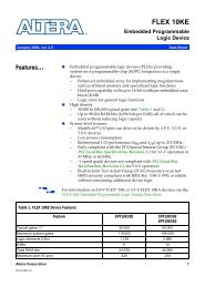
1. Pin Configurations<br />
Figure 1-1.<br />
Pinout <strong>ATmega48PA</strong>/<strong>88PA</strong>/<strong>168PA</strong>/<strong>328P</strong><br />
TQFP Top View<br />
PDIP<br />
(PCINT19/OC2B/INT1) PD3<br />
(PCINT20/XCK/T0) PD4<br />
GND<br />
VCC<br />
GND<br />
VCC<br />
(PCINT6/XTAL1/TOSC1) PB6<br />
(PCINT7/XTAL2/TOSC2) PB7<br />
1<br />
2<br />
3<br />
4<br />
5<br />
6<br />
7<br />
8<br />
PD2 (INT0/PCINT18)<br />
PD1 (TXD/PCINT17)<br />
PD0 (RXD/PCINT16)<br />
PC6 (RESET/PCINT14)<br />
PC5 (ADC5/SCL/PCINT13)<br />
PC4 (ADC4/SDA/PCINT12)<br />
PC3 (ADC3/PCINT11)<br />
PC2 (ADC2/PCINT10)<br />
32<br />
31<br />
30<br />
29<br />
28<br />
27<br />
26<br />
25<br />
9<br />
10<br />
11<br />
12<br />
13<br />
14<br />
15<br />
16<br />
(PCINT21/OC0B/T1) PD5<br />
(PCINT22/OC0A/AIN0) PD6<br />
(PCINT23/AIN1) PD7<br />
(PCINT0/CLKO/ICP1) PB0<br />
(PCINT1/OC1A) PB1<br />
(PCINT2/SS/OC1B) PB2<br />
(PCINT3/OC2A/MOSI) PB3<br />
(PCINT4/MISO) PB4<br />
24<br />
23<br />
22<br />
21<br />
20<br />
19<br />
18<br />
17<br />
PC1 (ADC1/PCINT9)<br />
PC0 (ADC0/PCINT8)<br />
ADC7<br />
GND<br />
AREF<br />
ADC6<br />
AVCC<br />
PB5 (SCK/PCINT5)<br />
(PCINT14/RESET) PC6<br />
(PCINT16/RXD) PD0<br />
(PCINT17/TXD) PD1<br />
(PCINT18/INT0) PD2<br />
(PCINT19/OC2B/INT1) PD3<br />
(PCINT20/XCK/T0) PD4<br />
VCC<br />
GND<br />
(PCINT6/XTAL1/TOSC1) PB6<br />
(PCINT7/XTAL2/TOSC2) PB7<br />
(PCINT21/OC0B/T1) PD5<br />
(PCINT22/OC0A/AIN0) PD6<br />
(PCINT23/AIN1) PD7<br />
(PCINT0/CLKO/ICP1) PB0<br />
1<br />
2<br />
3<br />
4<br />
5<br />
6<br />
7<br />
8<br />
9<br />
10<br />
11<br />
12<br />
13<br />
14<br />
28<br />
27<br />
26<br />
25<br />
24<br />
23<br />
22<br />
21<br />
20<br />
19<br />
18<br />
17<br />
16<br />
15<br />
PC5 (ADC5/SCL/PCINT13)<br />
PC4 (ADC4/SDA/PCINT12)<br />
PC3 (ADC3/PCINT11)<br />
PC2 (ADC2/PCINT10)<br />
PC1 (ADC1/PCINT9)<br />
PC0 (ADC0/PCINT8)<br />
GND<br />
AREF<br />
AVCC<br />
PB5 (SCK/PCINT5)<br />
PB4 (MISO/PCINT4)<br />
PB3 (MOSI/OC2A/PCINT3)<br />
PB2 (SS/OC1B/PCINT2)<br />
PB1 (OC1A/PCINT1)<br />
28 MLF Top View<br />
32 MLF Top View<br />
28<br />
27<br />
26<br />
25<br />
24<br />
23<br />
22<br />
32<br />
31<br />
30<br />
29<br />
28<br />
27<br />
26<br />
25<br />
PD2 (INT0/PCINT18)<br />
PD1 (TXD/PCINT17)<br />
PD0 (RXD/PCINT16)<br />
PC6 (RESET/PCINT14)<br />
PC5 (ADC5/SCL/PCINT13)<br />
PC4 (ADC4/SDA/PCINT12)<br />
PC3 (ADC3/PCINT11)<br />
PC2 (ADC2/PCINT10)<br />
1<br />
2<br />
3<br />
4<br />
5<br />
6<br />
7<br />
8<br />
9<br />
10<br />
11<br />
12<br />
13<br />
14<br />
PD2 (INT0/PCINT18)<br />
PD1 (TXD/PCINT17)<br />
PD0 (RXD/PCINT16)<br />
PC6 (RESET/PCINT14)<br />
PC5 (ADC5/SCL/PCINT13)<br />
PC4 (ADC4/SDA/PCINT12)<br />
PC3 (ADC3/PCINT11)<br />
(PCINT19/OC2B/INT1) PD3<br />
(PCINT20/XCK/T0) PD4<br />
VCC<br />
GND<br />
(PCINT6/XTAL1/TOSC1) PB6<br />
(PCINT7/XTAL2/TOSC2) PB7<br />
(PCINT21/OC0B/T1) PD5<br />
21<br />
20<br />
19<br />
18<br />
17<br />
16<br />
15<br />
PC2 (ADC2/PCINT10)<br />
PC1 (ADC1/PCINT9)<br />
PC0 (ADC0/PCINT8)<br />
GND<br />
AREF<br />
AVCC<br />
PB5 (SCK/PCINT5)<br />
(PCINT19/OC2B/INT1) PD3<br />
(PCINT20/XCK/T0) PD4<br />
GND<br />
VCC<br />
GND<br />
VCC<br />
(PCINT6/XTAL1/TOSC1) PB6<br />
(PCINT7/XTAL2/TOSC2) PB7<br />
1<br />
2<br />
3<br />
4<br />
5<br />
6<br />
7<br />
8<br />
24<br />
23<br />
22<br />
21<br />
20<br />
19<br />
18<br />
17<br />
PC1 (ADC1/PCINT9)<br />
PC0 (ADC0/PCINT8)<br />
ADC7<br />
GND<br />
AREF<br />
ADC6<br />
AVCC<br />
PB5 (SCK/PCINT5)<br />
NOTE: Bottom pad should be soldered to ground.<br />
(PCINT22/OC0A/AIN0) PD6<br />
(PCINT23/AIN1) PD7<br />
(PCINT0/CLKO/ICP1) PB0<br />
(PCINT1/OC1A) PB1<br />
(PCINT2/SS/OC1B) PB2<br />
(PCINT3/OC2A/MOSI) PB3<br />
(PCINT4/MISO) PB4<br />
NOTE: Bottom pad should be soldered to ground.<br />
9<br />
10<br />
11<br />
12<br />
13<br />
14<br />
15<br />
16<br />
(PCINT21/OC0B/T1) PD5<br />
(PCINT22/OC0A/AIN0) PD6<br />
(PCINT23/AIN1) PD7<br />
(PCINT0/CLKO/ICP1) PB0<br />
(PCINT1/OC1A) PB1<br />
(PCINT2/SS/OC1B) PB2<br />
(PCINT3/OC2A/MOSI) PB3<br />
(PCINT4/MISO) PB4<br />
8161DS–AVR–10/09<br />
2
<strong>ATmega48PA</strong>/<strong>88PA</strong>/<strong>168PA</strong>/<strong>328P</strong><br />
1.1 Pin Descriptions<br />
1.1.1 VCC<br />
1.1.2 GND<br />
Digital supply voltage.<br />
Ground.<br />
1.1.3 Port B (PB7:0) XTAL1/XTAL2/TOSC1/TOSC2<br />
Port B is an 8-bit bi-directional I/O port with internal pull-up resistors (selected for each bit). The<br />
Port B output buffers have symmetrical drive characteristics with both high sink and source<br />
capability. As inputs, Port B pins that are externally pulled low will source current if the pull-up<br />
resistors are activated. The Port B pins are tri-stated when a reset condition becomes active,<br />
even if the clock is not running.<br />
1.1.4 Port C (PC5:0)<br />
Depending on the clock selection fuse settings, PB6 can be used as input to the inverting Oscillator<br />
amplifier and input to the internal clock operating circuit.<br />
Depending on the clock selection fuse settings, PB7 can be used as output from the inverting<br />
Oscillator amplifier.<br />
If the Internal Calibrated RC Oscillator is used as chip clock source, PB7..6 is used as TOSC2..1<br />
input for the Asynchronous Timer/Counter2 if the AS2 bit in ASSR is set.<br />
The various special features of Port B are elaborated in ”Alternate Functions of Port B” on page<br />
76 and ”System Clock and Clock Options” on page 26.<br />
Port C is a 7-bit bi-directional I/O port with internal pull-up resistors (selected for each bit). The<br />
PC5..0 output buffers have symmetrical drive characteristics with both high sink and source<br />
capability. As inputs, Port C pins that are externally pulled low will source current if the pull-up<br />
resistors are activated. The Port C pins are tri-stated when a reset condition becomes active,<br />
even if the clock is not running.<br />
1.1.5 PC6/RESET<br />
If the RSTDISBL Fuse is programmed, PC6 is used as an I/O pin. Note that the electrical characteristics<br />
of PC6 differ from those of the other pins of Port C.<br />
If the RSTDISBL Fuse is unprogrammed, PC6 is used as a Reset input. A low level on this pin<br />
for longer than the minimum pulse length will generate a Reset, even if the clock is not running.<br />
The minimum pulse length is given in Table 28-3 on page 308. Shorter pulses are not guaranteed<br />
to generate a Reset.<br />
The various special features of Port C are elaborated in ”Alternate Functions of Port C” on page<br />
79.<br />
1.1.6 Port D (PD7:0)<br />
Port D is an 8-bit bi-directional I/O port with internal pull-up resistors (selected for each bit). The<br />
Port D output buffers have symmetrical drive characteristics with both high sink and source<br />
capability. As inputs, Port D pins that are externally pulled low will source current if the pull-up<br />
resistors are activated. The Port D pins are tri-stated when a reset condition becomes active,<br />
even if the clock is not running.<br />
8161DS–AVR–10/09<br />
3
<strong>ATmega48PA</strong>/<strong>88PA</strong>/<strong>168PA</strong>/<strong>328P</strong><br />
The various special features of Port D are elaborated in ”Alternate Functions of Port D” on page<br />
82.<br />
1.1.7 AV CC<br />
AV CC is the supply voltage pin for the A/D Converter, PC3:0, and ADC7:6. It should be externally<br />
connected to V CC , even if the ADC is not used. If the ADC is used, it should be connected to V CC<br />
through a low-pass filter. Note that PC6..4 use digital supply voltage, V CC .<br />
1.1.8 AREF<br />
AREF is the analog reference pin for the A/D Converter.<br />
1.1.9 ADC7:6 (TQFP and QFN/MLF Package Only)<br />
In the TQFP and QFN/MLF package, ADC7:6 serve as analog inputs to the A/D converter.<br />
These pins are powered from the analog supply and serve as 10-bit ADC channels.<br />
8161DS–AVR–10/09<br />
4
<strong>ATmega48PA</strong>/<strong>88PA</strong>/<strong>168PA</strong>/<strong>328P</strong><br />
2. Overview<br />
The <strong>ATmega48PA</strong>/<strong>88PA</strong>/<strong>168PA</strong>/<strong>328P</strong> is a low-power CMOS 8-bit microcontroller based on the<br />
AVR enhanced RISC architecture. By executing powerful instructions in a single clock cycle, the<br />
<strong>ATmega48PA</strong>/<strong>88PA</strong>/<strong>168PA</strong>/<strong>328P</strong> achieves throughputs approaching 1 MIPS per MHz allowing<br />
the system designer to optimize power consumption versus processing speed.<br />
2.1 Block Diagram<br />
Figure 2-1.<br />
Block Diagram<br />
GND<br />
VCC<br />
Watchdog<br />
Timer<br />
Watchdog<br />
Oscillator<br />
Power<br />
Supervision<br />
POR / BOD &<br />
RESET<br />
debugWIRE<br />
PROGRAM<br />
LOGIC<br />
Oscillator<br />
Circuits /<br />
Clock<br />
Generation<br />
Flash<br />
SRAM<br />
EEPROM<br />
CPU<br />
AVCC<br />
AREF<br />
GND<br />
8bit T/C 0<br />
16bit T/C 1<br />
A/D Conv.<br />
2<br />
DATABUS<br />
8bit T/C 2<br />
Analog<br />
Comp.<br />
Internal<br />
Bandgap<br />
6<br />
USART 0<br />
SPI<br />
TWI<br />
PORT D (8)<br />
PORT B (8)<br />
PORT C (7)<br />
RESET<br />
XTAL[1..2]<br />
PD[0..7]<br />
PB[0..7]<br />
PC[0..6]<br />
ADC[6..7]<br />
The AVR core combines a rich instruction set with 32 general purpose working registers. All the<br />
32 registers are directly connected to the Arithmetic Logic Unit (ALU), allowing two independent<br />
registers to be accessed in one single instruction executed in one clock cycle. The resulting<br />
8161DS–AVR–10/09<br />
5
<strong>ATmega48PA</strong>/<strong>88PA</strong>/<strong>168PA</strong>/<strong>328P</strong><br />
architecture is more code efficient while achieving throughputs up to ten times faster than conventional<br />
CISC microcontrollers.<br />
The <strong>ATmega48PA</strong>/<strong>88PA</strong>/<strong>168PA</strong>/<strong>328P</strong> provides the following features: 4/8/16/32K bytes of In-<br />
System Programmable Flash with Read-While-Write capabilities, 256/512/512/1K bytes<br />
EEPROM, 512/1K/1K/2K bytes SRAM, 23 general purpose I/O lines, 32 general purpose working<br />
registers, three flexible Timer/Counters with compare modes, internal and external<br />
interrupts, a serial programmable USART, a byte-oriented 2-wire Serial Interface, an SPI serial<br />
port, a 6-channel 10-bit ADC (8 channels in TQFP and QFN/MLF packages), a programmable<br />
Watchdog Timer with internal Oscillator, and five software selectable power saving modes. The<br />
Idle mode stops the CPU while allowing the SRAM, Timer/Counters, USART, 2-wire Serial Interface,<br />
SPI port, and interrupt system to continue functioning. The Power-down mode saves the<br />
register contents but freezes the Oscillator, disabling all other chip functions until the next interrupt<br />
or hardware reset. In Power-save mode, the asynchronous timer continues to run, allowing<br />
the user to maintain a timer base while the rest of the device is sleeping. The ADC Noise Reduction<br />
mode stops the CPU and all I/O modules except asynchronous timer and ADC, to minimize<br />
switching noise during ADC conversions. In Standby mode, the crystal/resonator Oscillator is<br />
running while the rest of the device is sleeping. This allows very fast start-up combined with low<br />
power consumption.<br />
The device is manufactured using <strong>Atmel</strong>’s high density non-volatile memory technology. The<br />
On-chip ISP Flash allows the program memory to be reprogrammed In-System through an SPI<br />
serial interface, by a conventional non-volatile memory programmer, or by an On-chip Boot program<br />
running on the AVR core. The Boot program can use any interface to download the<br />
application program in the Application Flash memory. Software in the Boot Flash section will<br />
continue to run while the Application Flash section is updated, providing true Read-While-Write<br />
operation. By combining an 8-bit RISC CPU with In-System Self-Programmable Flash on a<br />
monolithic chip, the <strong>Atmel</strong> <strong>ATmega48PA</strong>/<strong>88PA</strong>/<strong>168PA</strong>/<strong>328P</strong> is a powerful microcontroller that<br />
provides a highly flexible and cost effective solution to many embedded control applications.<br />
The <strong>ATmega48PA</strong>/<strong>88PA</strong>/<strong>168PA</strong>/<strong>328P</strong> AVR is supported with a full suite of program and system<br />
development tools including: C Compilers, Macro Assemblers, Program Debugger/Simulators,<br />
In-Circuit Emulators, and Evaluation kits.<br />
2.2 Comparison Between <strong>ATmega48PA</strong>, ATmega<strong>88PA</strong>, ATmega<strong>168PA</strong> and ATmega<strong>328P</strong><br />
The <strong>ATmega48PA</strong>, ATmega<strong>88PA</strong>, ATmega<strong>168PA</strong> and ATmega<strong>328P</strong> differ only in memory<br />
sizes, boot loader support, and interrupt vector sizes. Table 2-1 summarizes the different memory<br />
and interrupt vector sizes for the three devices.<br />
Table 2-1.<br />
Memory Size Summary<br />
Device Flash EEPROM RAM Interrupt Vector Size<br />
<strong>ATmega48PA</strong> 4K Bytes 256 Bytes 512 Bytes 1 instruction word/vector<br />
ATmega<strong>88PA</strong> 8K Bytes 512 Bytes 1K Bytes 1 instruction word/vector<br />
ATmega<strong>168PA</strong> 16K Bytes 512 Bytes 1K Bytes 2 instruction words/vector<br />
ATmega<strong>328P</strong> 32K Bytes 1K Bytes 2K Bytes 2 instruction words/vector<br />
ATmega<strong>88PA</strong>, ATmega<strong>168PA</strong> and ATmega<strong>328P</strong> support a real Read-While-Write Self-Programming<br />
mechanism. There is a separate Boot Loader Section, and the SPM instruction can<br />
only execute from there. In <strong>ATmega48PA</strong>, there is no Read-While-Write support and no separate<br />
Boot Loader Section. The SPM instruction can execute from the entire Flash.<br />
8161DS–AVR–10/09<br />
6
<strong>ATmega48PA</strong>/<strong>88PA</strong>/<strong>168PA</strong>/<strong>328P</strong><br />
3. Resources<br />
A comprehensive set of development tools, application notes and datasheets are available for<br />
download on http://www.atmel.com/avr.<br />
Note: 1.<br />
4. Data Retention<br />
Reliability Qualification results show that the projected data retention failure rate is much less<br />
than 1 PPM over 20 years at 85°C or 100 years at 25°C.<br />
8161DS–AVR–10/09<br />
7
<strong>ATmega48PA</strong>/<strong>88PA</strong>/<strong>168PA</strong>/<strong>328P</strong><br />
5. Register Summary<br />
Address Name Bit 7 Bit 6 Bit 5 Bit 4 Bit 3 Bit 2 Bit 1 Bit 0 Page<br />
(0xFF) Reserved – – – – – – – –<br />
(0xFE) Reserved – – – – – – – –<br />
(0xFD) Reserved – – – – – – – –<br />
(0xFC) Reserved – – – – – – – –<br />
(0xFB) Reserved – – – – – – – –<br />
(0xFA) Reserved – – – – – – – –<br />
(0xF9) Reserved – – – – – – – –<br />
(0xF8) Reserved – – – – – – – –<br />
(0xF7) Reserved – – – – – – – –<br />
(0xF6) Reserved – – – – – – – –<br />
(0xF5) Reserved – – – – – – – –<br />
(0xF4) Reserved – – – – – – – –<br />
(0xF3) Reserved – – – – – – – –<br />
(0xF2) Reserved – – – – – – – –<br />
(0xF1) Reserved – – – – – – – –<br />
(0xF0) Reserved – – – – – – – –<br />
(0xEF) Reserved – – – – – – – –<br />
(0xEE) Reserved – – – – – – – –<br />
(0xED) Reserved – – – – – – – –<br />
(0xEC) Reserved – – – – – – – –<br />
(0xEB) Reserved – – – – – – – –<br />
(0xEA) Reserved – – – – – – – –<br />
(0xE9) Reserved – – – – – – – –<br />
(0xE8) Reserved – – – – – – – –<br />
(0xE7) Reserved – – – – – – – –<br />
(0xE6) Reserved – – – – – – – –<br />
(0xE5) Reserved – – – – – – – –<br />
(0xE4) Reserved – – – – – – – –<br />
(0xE3) Reserved – – – – – – – –<br />
(0xE2) Reserved – – – – – – – –<br />
(0xE1) Reserved – – – – – – – –<br />
(0xE0) Reserved – – – – – – – –<br />
(0xDF) Reserved – – – – – – – –<br />
(0xDE) Reserved – – – – – – – –<br />
(0xDD) Reserved – – – – – – – –<br />
(0xDC) Reserved – – – – – – – –<br />
(0xDB) Reserved – – – – – – – –<br />
(0xDA) Reserved – – – – – – – –<br />
(0xD9) Reserved – – – – – – – –<br />
(0xD8) Reserved – – – – – – – –<br />
(0xD7) Reserved – – – – – – – –<br />
(0xD6) Reserved – – – – – – – –<br />
(0xD5) Reserved – – – – – – – –<br />
(0xD4) Reserved – – – – – – – –<br />
(0xD3) Reserved – – – – – – – –<br />
(0xD2) Reserved – – – – – – – –<br />
(0xD1) Reserved – – – – – – – –<br />
(0xD0) Reserved – – – – – – – –<br />
(0xCF) Reserved – – – – – – – –<br />
(0xCE) Reserved – – – – – – – –<br />
(0xCD) Reserved – – – – – – – –<br />
(0xCC) Reserved – – – – – – – –<br />
(0xCB) Reserved – – – – – – – –<br />
(0xCA) Reserved – – – – – – – –<br />
(0xC9) Reserved – – – – – – – –<br />
(0xC8) Reserved – – – – – – – –<br />
(0xC7) Reserved – – – – – – – –<br />
(0xC6) UDR0 USART I/O Data Register 189<br />
(0xC5) UBRR0H USART Baud Rate Register High 193<br />
(0xC4) UBRR0L USART Baud Rate Register Low 193<br />
(0xC3) Reserved – – – – – – – –<br />
(0xC2) UCSR0C UMSEL01 UMSEL00 UPM01 UPM00 USBS0 UCSZ01 /UDORD0 UCSZ00 / UCPHA0 UCPOL0 191/206<br />
8161DS–AVR–10/09<br />
8
<strong>ATmega48PA</strong>/<strong>88PA</strong>/<strong>168PA</strong>/<strong>328P</strong><br />
Address Name Bit 7 Bit 6 Bit 5 Bit 4 Bit 3 Bit 2 Bit 1 Bit 0 Page<br />
(0xC1) UCSR0B RXCIE0 TXCIE0 UDRIE0 RXEN0 TXEN0 UCSZ02 RXB80 TXB80 190<br />
(0xC0) UCSR0A RXC0 TXC0 UDRE0 FE0 DOR0 UPE0 U2X0 MPCM0 189<br />
(0xBF) Reserved – – – – – – – –<br />
(0xBE) Reserved – – – – – – – –<br />
(0xBD) TWAMR TWAM6 TWAM5 TWAM4 TWAM3 TWAM2 TWAM1 TWAM0 – 239<br />
(0xBC) TWCR TWINT TWEA TWSTA TWSTO TWWC TWEN – TWIE 236<br />
(0xBB) TWDR 2-wire Serial Interface Data Register 238<br />
(0xBA) TWAR TWA6 TWA5 TWA4 TWA3 TWA2 TWA1 TWA0 TWGCE 239<br />
(0xB9) TWSR TWS7 TWS6 TWS5 TWS4 TWS3 – TWPS1 TWPS0 238<br />
(0xB8) TWBR 2-wire Serial Interface Bit Rate Register 236<br />
(0xB7) Reserved – – – – – – –<br />
(0xB6) ASSR – EXCLK AS2 TCN2UB OCR2AUB OCR2BUB TCR2AUB TCR2BUB 158<br />
(0xB5) Reserved – – – – – – – –<br />
(0xB4) OCR2B Timer/Counter2 Output Compare Register B 156<br />
(0xB3) OCR2A Timer/Counter2 Output Compare Register A 156<br />
(0xB2) TCNT2 Timer/Counter2 (8-bit) 156<br />
(0xB1) TCCR2B FOC2A FOC2B – – WGM22 CS22 CS21 CS20 155<br />
(0xB0) TCCR2A COM2A1 COM2A0 COM2B1 COM2B0 – – WGM21 WGM20 152<br />
(0xAF) Reserved – – – – – – – –<br />
(0xAE) Reserved – – – – – – – –<br />
(0xAD) Reserved – – – – – – – –<br />
(0xAC) Reserved – – – – – – – –<br />
(0xAB) Reserved – – – – – – – –<br />
(0xAA) Reserved – – – – – – – –<br />
(0xA9) Reserved – – – – – – – –<br />
(0xA8) Reserved – – – – – – – –<br />
(0xA7) Reserved – – – – – – – –<br />
(0xA6) Reserved – – – – – – – –<br />
(0xA5) Reserved – – – – – – – –<br />
(0xA4) Reserved – – – – – – – –<br />
(0xA3) Reserved – – – – – – – –<br />
(0xA2) Reserved – – – – – – – –<br />
(0xA1) Reserved – – – – – – – –<br />
(0xA0) Reserved – – – – – – – –<br />
(0x9F) Reserved – – – – – – – –<br />
(0x9E) Reserved – – – – – – – –<br />
(0x9D) Reserved – – – – – – – –<br />
(0x9C) Reserved – – – – – – – –<br />
(0x9B) Reserved – – – – – – – –<br />
(0x9A) Reserved – – – – – – – –<br />
(0x99) Reserved – – – – – – – –<br />
(0x98) Reserved – – – – – – – –<br />
(0x97) Reserved – – – – – – – –<br />
(0x96) Reserved – – – – – – – –<br />
(0x95) Reserved – – – – – – – –<br />
(0x94) Reserved – – – – – – – –<br />
(0x93) Reserved – – – – – – – –<br />
(0x92) Reserved – – – – – – – –<br />
(0x91) Reserved – – – – – – – –<br />
(0x90) Reserved – – – – – – – –<br />
(0x8F) Reserved – – – – – – – –<br />
(0x8E) Reserved – – – – – – – –<br />
(0x8D) Reserved – – – – – – – –<br />
(0x8C) Reserved – – – – – – – –<br />
(0x8B) OCR1BH Timer/Counter1 - Output Compare Register B High Byte 132<br />
(0x8A) OCR1BL Timer/Counter1 - Output Compare Register B Low Byte 132<br />
(0x89) OCR1AH Timer/Counter1 - Output Compare Register A High Byte 132<br />
(0x88) OCR1AL Timer/Counter1 - Output Compare Register A Low Byte 132<br />
(0x87) ICR1H Timer/Counter1 - Input Capture Register High Byte 133<br />
(0x86) ICR1L Timer/Counter1 - Input Capture Register Low Byte 133<br />
(0x85) TCNT1H Timer/Counter1 - Counter Register High Byte 132<br />
(0x84) TCNT1L Timer/Counter1 - Counter Register Low Byte 132<br />
(0x83) Reserved – – – – – – – –<br />
(0x82) TCCR1C FOC1A FOC1B – – – – – – 131<br />
(0x81) TCCR1B ICNC1 ICES1 – WGM13 WGM12 CS12 CS11 CS10 130<br />
(0x80) TCCR1A COM1A1 COM1A0 COM1B1 COM1B0 – – WGM11 WGM10 128<br />
8161DS–AVR–10/09<br />
9
<strong>ATmega48PA</strong>/<strong>88PA</strong>/<strong>168PA</strong>/<strong>328P</strong><br />
Address Name Bit 7 Bit 6 Bit 5 Bit 4 Bit 3 Bit 2 Bit 1 Bit 0 Page<br />
(0x7F) DIDR1 – – – – – – AIN1D AIN0D 244<br />
(0x7E) DIDR0 – – ADC5D ADC4D ADC3D ADC2D ADC1D ADC0D 261<br />
(0x7D) Reserved – – – – – – – –<br />
(0x7C) ADMUX REFS1 REFS0 ADLAR – MUX3 MUX2 MUX1 MUX0 257<br />
(0x7B) ADCSRB – ACME – – – ADTS2 ADTS1 ADTS0 260<br />
(0x7A) ADCSRA ADEN ADSC ADATE ADIF ADIE ADPS2 ADPS1 ADPS0 258<br />
(0x79) ADCH ADC Data Register High byte 260<br />
(0x78) ADCL ADC Data Register Low byte 260<br />
(0x77) Reserved – – – – – – – –<br />
(0x76) Reserved – – – – – – – –<br />
(0x75) Reserved – – – – – – – –<br />
(0x74) Reserved – – – – – – – –<br />
(0x73) Reserved – – – – – – – –<br />
(0x72) Reserved – – – – – – – –<br />
(0x71) Reserved – – – – – – – –<br />
(0x70) TIMSK2 – – – – – OCIE2B OCIE2A TOIE2 157<br />
(0x6F) TIMSK1 – – ICIE1 – – OCIE1B OCIE1A TOIE1 133<br />
(0x6E) TIMSK0 – – – – – OCIE0B OCIE0A TOIE0 105<br />
(0x6D) PCMSK2 PCINT23 PCINT22 PCINT21 PCINT20 PCINT19 PCINT18 PCINT17 PCINT16 68<br />
(0x6C) PCMSK1 – PCINT14 PCINT13 PCINT12 PCINT11 PCINT10 PCINT9 PCINT8 68<br />
(0x6B) PCMSK0 PCINT7 PCINT6 PCINT5 PCINT4 PCINT3 PCINT2 PCINT1 PCINT0 68<br />
(0x6A) Reserved – – – – – – – –<br />
(0x69) EICRA – – – – ISC11 ISC10 ISC01 ISC00 65<br />
(0x68) PCICR – – – – – PCIE2 PCIE1 PCIE0<br />
(0x67) Reserved – – – – – – – –<br />
(0x66) OSCCAL Oscillator Calibration Register 37<br />
(0x65) Reserved – – – – – – – –<br />
(0x64) PRR PRTWI PRTIM2 PRTIM0 – PRTIM1 PRSPI PRUSART0 PRADC 42<br />
(0x63) Reserved – – – – – – – –<br />
(0x62) Reserved – – – – – – – –<br />
(0x61) CLKPR CLKPCE – – – CLKPS3 CLKPS2 CLKPS1 CLKPS0 37<br />
(0x60) WDTCSR WDIF WDIE WDP3 WDCE WDE WDP2 WDP1 WDP0 54<br />
0x3F (0x5F) SREG I T H S V N Z C 9<br />
0x3E (0x5E) SPH – – – – – (SP10) 5. SP9 SP8 12<br />
0x3D (0x5D) SPL SP7 SP6 SP5 SP4 SP3 SP2 SP1 SP0 12<br />
0x3C (0x5C) Reserved – – – – – – – –<br />
0x3B (0x5B) Reserved – – – – – – – –<br />
0x3A (0x5A) Reserved – – – – – – – –<br />
0x39 (0x59) Reserved – – – – – – – –<br />
0x38 (0x58) Reserved – – – – – – – –<br />
0x37 (0x57) SPMCSR SPMIE (RWWSB) 5. – (RWWSRE) 5. BLBSET PGWRT PGERS SELFPRGEN 284<br />
0x36 (0x56) Reserved – – – – – – – –<br />
0x35 (0x55) MCUCR – BODS BODSE PUD – – IVSEL IVCE 44/62/86<br />
0x34 (0x54) MCUSR – – – – WDRF BORF EXTRF PORF 54<br />
0x33 (0x53) SMCR – – – – SM2 SM1 SM0 SE 40<br />
0x32 (0x52) Reserved – – – – – – – –<br />
0x31 (0x51) Reserved – – – – – – – –<br />
0x30 (0x50) ACSR ACD ACBG ACO ACI ACIE ACIC ACIS1 ACIS0 242<br />
0x2F (0x4F) Reserved – – – – – – – –<br />
0x2E (0x4E) SPDR SPI Data Register 169<br />
0x2D (0x4D) SPSR SPIF WCOL – – – – – SPI2X 168<br />
0x2C (0x4C) SPCR SPIE SPE DORD MSTR CPOL CPHA SPR1 SPR0 167<br />
0x2B (0x4B) GPIOR2 General Purpose I/O Register 2 25<br />
0x2A (0x4A) GPIOR1 General Purpose I/O Register 1 25<br />
0x29 (0x49) Reserved – – – – – – – –<br />
0x28 (0x48) OCR0B Timer/Counter0 Output Compare Register B<br />
0x27 (0x47) OCR0A Timer/Counter0 Output Compare Register A<br />
0x26 (0x46) TCNT0 Timer/Counter0 (8-bit)<br />
0x25 (0x45) TCCR0B FOC0A FOC0B – – WGM02 CS02 CS01 CS00<br />
0x24 (0x44) TCCR0A COM0A1 COM0A0 COM0B1 COM0B0 – – WGM01 WGM00<br />
0x23 (0x43) GTCCR TSM – – – – – PSRASY PSRSYNC 137/159<br />
0x22 (0x42) EEARH (EEPROM Address Register High Byte) 5. 21<br />
0x21 (0x41) EEARL EEPROM Address Register Low Byte 21<br />
0x20 (0x40) EEDR EEPROM Data Register 21<br />
0x1F (0x3F) EECR – – EEPM1 EEPM0 EERIE EEMPE EEPE EERE 21<br />
0x1E (0x3E) GPIOR0 General Purpose I/O Register 0 25<br />
8161DS–AVR–10/09<br />
10
<strong>ATmega48PA</strong>/<strong>88PA</strong>/<strong>168PA</strong>/<strong>328P</strong><br />
Address Name Bit 7 Bit 6 Bit 5 Bit 4 Bit 3 Bit 2 Bit 1 Bit 0 Page<br />
0x1D (0x3D) EIMSK – – – – – – INT1 INT0 66<br />
0x1C (0x3C) EIFR – – – – – – INTF1 INTF0 66<br />
0x1B (0x3B) PCIFR – – – – – PCIF2 PCIF1 PCIF0<br />
0x1A (0x3A) Reserved – – – – – – – –<br />
0x19 (0x39) Reserved – – – – – – – –<br />
0x18 (0x38) Reserved – – – – – – – –<br />
0x17 (0x37) TIFR2 – – – – – OCF2B OCF2A TOV2 157<br />
0x16 (0x36) TIFR1 – – ICF1 – – OCF1B OCF1A TOV1 134<br />
0x15 (0x35) TIFR0 – – – – – OCF0B OCF0A TOV0<br />
0x14 (0x34) Reserved – – – – – – – –<br />
0x13 (0x33) Reserved – – – – – – – –<br />
0x12 (0x32) Reserved – – – – – – – –<br />
0x11 (0x31) Reserved – – – – – – – –<br />
0x10 (0x30) Reserved – – – – – – – –<br />
0x0F (0x2F) Reserved – – – – – – – –<br />
0x0E (0x2E) Reserved – – – – – – – –<br />
0x0D (0x2D) Reserved – – – – – – – –<br />
0x0C (0x2C) Reserved – – – – – – – –<br />
0x0B (0x2B) PORTD PORTD7 PORTD6 PORTD5 PORTD4 PORTD3 PORTD2 PORTD1 PORTD0 87<br />
0x0A (0x2A) DDRD DDD7 DDD6 DDD5 DDD4 DDD3 DDD2 DDD1 DDD0 87<br />
0x09 (0x29) PIND PIND7 PIND6 PIND5 PIND4 PIND3 PIND2 PIND1 PIND0 87<br />
0x08 (0x28) PORTC – PORTC6 PORTC5 PORTC4 PORTC3 PORTC2 PORTC1 PORTC0 86<br />
0x07 (0x27) DDRC – DDC6 DDC5 DDC4 DDC3 DDC2 DDC1 DDC0 86<br />
0x06 (0x26) PINC – PINC6 PINC5 PINC4 PINC3 PINC2 PINC1 PINC0 86<br />
0x05 (0x25) PORTB PORTB7 PORTB6 PORTB5 PORTB4 PORTB3 PORTB2 PORTB1 PORTB0 86<br />
0x04 (0x24) DDRB DDB7 DDB6 DDB5 DDB4 DDB3 DDB2 DDB1 DDB0 86<br />
0x03 (0x23) PINB PINB7 PINB6 PINB5 PINB4 PINB3 PINB2 PINB1 PINB0 86<br />
0x02 (0x22) Reserved – – – – – – – –<br />
0x01 (0x21) Reserved – – – – – – – –<br />
0x0 (0x20) Reserved – – – – – – – –<br />
Note: 1. For compatibility with future devices, reserved bits should be written to zero if accessed. Reserved I/O memory addresses<br />
should never be written.<br />
2. I/O Registers within the address range 0x00 - 0x1F are directly bit-accessible using the SBI and CBI instructions. In these<br />
registers, the value of single bits can be checked by using the SBIS and SBIC instructions.<br />
3. Some of the Status Flags are cleared by writing a logical one to them. Note that, unlike most other AVRs, the CBI and SBI<br />
instructions will only operate on the specified bit, and can therefore be used on registers containing such Status Flags. The<br />
CBI and SBI instructions work with registers 0x00 to 0x1F only.<br />
4. When using the I/O specific commands IN and OUT, the I/O addresses 0x00 - 0x3F must be used. When addressing I/O<br />
Registers as data space using LD and ST instructions, 0x20 must be added to these addresses. The<br />
<strong>ATmega48PA</strong>/<strong>88PA</strong>/<strong>168PA</strong>/<strong>328P</strong> is a complex microcontroller with more peripheral units than can be supported within the 64<br />
location reserved in Opcode for the IN and OUT instructions. For the Extended I/O space from 0x60 - 0xFF in SRAM, only<br />
the ST/STS/STD and LD/LDS/LDD instructions can be used.<br />
5. Only valid for ATmega<strong>88PA</strong>.<br />
8161DS–AVR–10/09<br />
11
<strong>ATmega48PA</strong>/<strong>88PA</strong>/<strong>168PA</strong>/<strong>328P</strong><br />
6. Instruction Set Summary<br />
Mnemonics Operands Description Operation Flags #Clocks<br />
ARITHMETIC AND LOGIC INSTRUCTIONS<br />
ADD Rd, Rr Add two Registers Rd ← Rd + Rr Z,C,N,V,H 1<br />
ADC Rd, Rr Add with Carry two Registers Rd ← Rd + Rr + C Z,C,N,V,H 1<br />
ADIW Rdl,K Add Immediate to Word Rdh:Rdl ← Rdh:Rdl + K Z,C,N,V,S 2<br />
SUB Rd, Rr Subtract two Registers Rd ← Rd - Rr Z,C,N,V,H 1<br />
SUBI Rd, K Subtract Constant from Register Rd ← Rd - K Z,C,N,V,H 1<br />
SBC Rd, Rr Subtract with Carry two Registers Rd ← Rd - Rr - C Z,C,N,V,H 1<br />
SBCI Rd, K Subtract with Carry Constant from Reg. Rd ← Rd - K - C Z,C,N,V,H 1<br />
SBIW Rdl,K Subtract Immediate from Word Rdh:Rdl ← Rdh:Rdl - K Z,C,N,V,S 2<br />
AND Rd, Rr Logical AND Registers Rd ← Rd • Rr Z,N,V 1<br />
ANDI Rd, K Logical AND Register and Constant Rd ← Rd • K Z,N,V 1<br />
OR Rd, Rr Logical OR Registers Rd ← Rd v Rr Z,N,V 1<br />
ORI Rd, K Logical OR Register and Constant Rd ← Rd v K Z,N,V 1<br />
EOR Rd, Rr Exclusive OR Registers Rd ← Rd ⊕ Rr Z,N,V 1<br />
COM Rd One’s Complement Rd ← 0xFF − Rd Z,C,N,V 1<br />
NEG Rd Two’s Complement Rd ← 0x00 − Rd Z,C,N,V,H 1<br />
SBR Rd,K Set Bit(s) in Register Rd ← Rd v K Z,N,V 1<br />
CBR Rd,K Clear Bit(s) in Register Rd ← Rd • (0xFF - K) Z,N,V 1<br />
INC Rd Increment Rd ← Rd + 1 Z,N,V 1<br />
DEC Rd Decrement Rd ← Rd − 1 Z,N,V 1<br />
TST Rd Test for Zero or Minus Rd ← Rd • Rd Z,N,V 1<br />
CLR Rd Clear Register Rd ← Rd ⊕ Rd Z,N,V 1<br />
SER Rd Set Register Rd ← 0xFF None 1<br />
MUL Rd, Rr Multiply Unsigned R1:R0 ← Rd x Rr Z,C 2<br />
MULS Rd, Rr Multiply Signed R1:R0 ← Rd x Rr Z,C 2<br />
MULSU Rd, Rr Multiply Signed with Unsigned R1:R0 ← Rd x Rr Z,C 2<br />
FMUL Rd, Rr Fractional Multiply Unsigned R1:R0 ← (Rd x Rr)
<strong>ATmega48PA</strong>/<strong>88PA</strong>/<strong>168PA</strong>/<strong>328P</strong><br />
Mnemonics Operands Description Operation Flags #Clocks<br />
BRIE k Branch if Interrupt Enabled if ( I = 1) then PC ← PC + k + 1 None 1/2<br />
BRID k Branch if Interrupt Disabled if ( I = 0) then PC ← PC + k + 1 None 1/2<br />
BIT AND BIT-TEST INSTRUCTIONS<br />
SBI P,b Set Bit in I/O Register I/O(P,b) ← 1 None 2<br />
CBI P,b Clear Bit in I/O Register I/O(P,b) ← 0 None 2<br />
LSL Rd Logical Shift Left Rd(n+1) ← Rd(n), Rd(0) ← 0 Z,C,N,V 1<br />
LSR Rd Logical Shift Right Rd(n) ← Rd(n+1), Rd(7) ← 0 Z,C,N,V 1<br />
ROL Rd Rotate Left Through Carry Rd(0)←C,Rd(n+1)← Rd(n),C←Rd(7) Z,C,N,V 1<br />
ROR Rd Rotate Right Through Carry Rd(7)←C,Rd(n)← Rd(n+1),C←Rd(0) Z,C,N,V 1<br />
ASR Rd Arithmetic Shift Right Rd(n) ← Rd(n+1), n=0..6 Z,C,N,V 1<br />
SWAP Rd Swap Nibbles Rd(3..0)←Rd(7..4),Rd(7..4)←Rd(3..0) None 1<br />
BSET s Flag Set SREG(s) ← 1 SREG(s) 1<br />
BCLR s Flag Clear SREG(s) ← 0 SREG(s) 1<br />
BST Rr, b Bit Store from Register to T T ← Rr(b) T 1<br />
BLD Rd, b Bit load from T to Register Rd(b) ← T None 1<br />
SEC Set Carry C ← 1 C 1<br />
CLC Clear Carry C ← 0 C 1<br />
SEN Set Negative Flag N ← 1 N 1<br />
CLN Clear Negative Flag N ← 0 N 1<br />
SEZ Set Zero Flag Z ← 1 Z 1<br />
CLZ Clear Zero Flag Z ← 0 Z 1<br />
SEI Global Interrupt Enable I ← 1 I 1<br />
CLI Global Interrupt Disable I ← 0 I 1<br />
SES Set Signed Test Flag S ← 1 S 1<br />
CLS Clear Signed Test Flag S ← 0 S 1<br />
SEV Set Twos Complement Overflow. V ← 1 V 1<br />
CLV Clear Twos Complement Overflow V ← 0 V 1<br />
SET Set T in SREG T ← 1 T 1<br />
CLT Clear T in SREG T ← 0 T 1<br />
SEH Set Half Carry Flag in SREG H ← 1 H 1<br />
CLH Clear Half Carry Flag in SREG H ← 0 H 1<br />
DATA TRANSFER INSTRUCTIONS<br />
MOV Rd, Rr Move Between Registers Rd ← Rr None 1<br />
MOVW Rd, Rr Copy Register Word Rd+1:Rd ← Rr+1:Rr None 1<br />
LDI Rd, K Load Immediate Rd ← K None 1<br />
LD Rd, X Load Indirect Rd ← (X) None 2<br />
LD Rd, X+ Load Indirect and Post-Inc. Rd ← (X), X ← X + 1 None 2<br />
LD Rd, - X Load Indirect and Pre-Dec. X ← X - 1, Rd ← (X) None 2<br />
LD Rd, Y Load Indirect Rd ← (Y) None 2<br />
LD Rd, Y+ Load Indirect and Post-Inc. Rd ← (Y), Y ← Y + 1 None 2<br />
LD Rd, - Y Load Indirect and Pre-Dec. Y ← Y - 1, Rd ← (Y) None 2<br />
LDD Rd,Y+q Load Indirect with Displacement Rd ← (Y + q) None 2<br />
LD Rd, Z Load Indirect Rd ← (Z) None 2<br />
LD Rd, Z+ Load Indirect and Post-Inc. Rd ← (Z), Z ← Z+1 None 2<br />
LD Rd, -Z Load Indirect and Pre-Dec. Z ← Z - 1, Rd ← (Z) None 2<br />
LDD Rd, Z+q Load Indirect with Displacement Rd ← (Z + q) None 2<br />
LDS Rd, k Load Direct from SRAM Rd ← (k) None 2<br />
ST X, Rr Store Indirect (X) ← Rr None 2<br />
ST X+, Rr Store Indirect and Post-Inc. (X) ← Rr, X ← X + 1 None 2<br />
ST - X, Rr Store Indirect and Pre-Dec. X ← X - 1, (X) ← Rr None 2<br />
ST Y, Rr Store Indirect (Y) ← Rr None 2<br />
ST Y+, Rr Store Indirect and Post-Inc. (Y) ← Rr, Y ← Y + 1 None 2<br />
ST - Y, Rr Store Indirect and Pre-Dec. Y ← Y - 1, (Y) ← Rr None 2<br />
STD Y+q,Rr Store Indirect with Displacement (Y + q) ← Rr None 2<br />
ST Z, Rr Store Indirect (Z) ← Rr None 2<br />
ST Z+, Rr Store Indirect and Post-Inc. (Z) ← Rr, Z ← Z + 1 None 2<br />
ST -Z, Rr Store Indirect and Pre-Dec. Z ← Z - 1, (Z) ← Rr None 2<br />
STD Z+q,Rr Store Indirect with Displacement (Z + q) ← Rr None 2<br />
STS k, Rr Store Direct to SRAM (k) ← Rr None 2<br />
LPM Load Program Memory R0 ← (Z) None 3<br />
LPM Rd, Z Load Program Memory Rd ← (Z) None 3<br />
LPM Rd, Z+ Load Program Memory and Post-Inc Rd ← (Z), Z ← Z+1 None 3<br />
SPM Store Program Memory (Z) ← R1:R0 None -<br />
IN Rd, P In Port Rd ← P None 1<br />
OUT P, Rr Out Port P ← Rr None 1<br />
PUSH Rr Push Register on Stack STACK ← Rr None 2<br />
8161DS–AVR–10/09<br />
13
<strong>ATmega48PA</strong>/<strong>88PA</strong>/<strong>168PA</strong>/<strong>328P</strong><br />
Mnemonics Operands Description Operation Flags #Clocks<br />
POP Rd Pop Register from Stack Rd ← STACK None 2<br />
MCU CONTROL INSTRUCTIONS<br />
NOP No Operation None 1<br />
SLEEP Sleep (see specific descr. for Sleep function) None 1<br />
WDR Watchdog Reset (see specific descr. for WDR/timer) None 1<br />
BREAK Break For On-chip Debug Only None N/A<br />
8161DS–AVR–10/09<br />
14
<strong>ATmega48PA</strong>/<strong>88PA</strong>/<strong>168PA</strong>/<strong>328P</strong><br />
7. Ordering Information<br />
7.1 <strong>ATmega48PA</strong><br />
Speed (MHz) Power Supply Ordering Code (2) Package (1) Operational Range<br />
20 (3) 1.8 - 5.5<br />
<strong>ATmega48PA</strong>-AU<br />
<strong>ATmega48PA</strong>-MMH (4)<br />
<strong>ATmega48PA</strong>-MU<br />
<strong>ATmega48PA</strong>-PU<br />
32A<br />
28M1<br />
32M1-A<br />
28P3<br />
Industrial<br />
(-40°C to 85°C)<br />
Note: 1. This device can also be supplied in wafer form. Please contact your local <strong>Atmel</strong> sales office for detailed ordering information<br />
and minimum quantities.<br />
2. Pb-free packaging complies to the European Directive for Restriction of Hazardous Substances (RoHS directive).Also<br />
Halide free and fully Green.<br />
3. See ”Speed Grades” on page 306.<br />
4. NiPdAu Lead Finish.<br />
Package Type<br />
32A<br />
28M1<br />
32M1-A<br />
28P3<br />
32-lead, Thin (1.0 mm) Plastic Quad Flat Package (TQFP)<br />
28-pad, 4 x 4 x 1.0 body, Lead Pitch 0.45 mm Quad Flat No-Lead/Micro Lead Frame Package (QFN/MLF)<br />
32-pad, 5 x 5 x 1.0 body, Lead Pitch 0.50 mm Quad Flat No-Lead/Micro Lead Frame Package (QFN/MLF)<br />
28-lead, 0.300” Wide, Plastic Dual Inline Package (PDIP)<br />
8161DS–AVR–10/09<br />
15
<strong>ATmega48PA</strong>/<strong>88PA</strong>/<strong>168PA</strong>/<strong>328P</strong><br />
7.2 ATmega<strong>88PA</strong><br />
Speed (MHz) Power Supply Ordering Code (2) Package (1) Operational Range<br />
20 (3) 1.8 - 5.5<br />
ATmega<strong>88PA</strong>-AU<br />
ATmega<strong>88PA</strong>-MMH (4)<br />
ATmega<strong>88PA</strong>-MU<br />
ATmega<strong>88PA</strong>-PU<br />
32A<br />
28M1<br />
32M1-A<br />
28P3<br />
Industrial<br />
(-40°C to 85°C)<br />
Note: 1. This device can also be supplied in wafer form. Please contact your local <strong>Atmel</strong> sales office for detailed ordering information<br />
and minimum quantities.<br />
2. Pb-free packaging complies to the European Directive for Restriction of Hazardous Substances (RoHS directive).Also<br />
Halide free and fully Green.<br />
3. See ”Speed Grades” on page 306.<br />
4. NiPdAu Lead Finish.<br />
Package Type<br />
32A<br />
28M1<br />
32M1-A<br />
28P3<br />
32-lead, Thin (1.0 mm) Plastic Quad Flat Package (TQFP)<br />
28-pad, 4 x 4 x 1.0 body, Lead Pitch 0.45 mm Quad Flat No-Lead/Micro Lead Frame Package (QFN/MLF)<br />
32-pad, 5 x 5 x 1.0 body, Lead Pitch 0.50 mm Quad Flat No-Lead/Micro Lead Frame Package (QFN/MLF)<br />
28-lead, 0.300” Wide, Plastic Dual Inline Package (PDIP)<br />
8161DS–AVR–10/09<br />
16
<strong>ATmega48PA</strong>/<strong>88PA</strong>/<strong>168PA</strong>/<strong>328P</strong><br />
7.3 ATmega<strong>168PA</strong><br />
Speed (MHz) (3) Power Supply Ordering Code (2) Package (1) Operational Range<br />
20 1.8 - 5.5<br />
ATmega<strong>168PA</strong>-AU<br />
ATmega<strong>168PA</strong>-MMH (4)<br />
ATmega<strong>168PA</strong>-MU<br />
ATmega<strong>168PA</strong>-PU<br />
32A<br />
28M1<br />
32M1-A<br />
28P3<br />
Industrial<br />
(-40°C to 85°C)<br />
Note: 1. This device can also be supplied in wafer form. Please contact your local <strong>Atmel</strong> sales office for detailed ordering information<br />
and minimum quantities.<br />
2. Pb-free packaging complies to the European Directive for Restriction of Hazardous Substances (RoHS directive).Also<br />
Halide free and fully Green.<br />
3. See ”Speed Grades” on page 312.<br />
4. NiPdAu Lead Finish.<br />
Package Type<br />
32A<br />
28M1<br />
32M1-A<br />
28P3<br />
32-lead, Thin (1.0 mm) Plastic Quad Flat Package (TQFP)<br />
28-pad, 4 x 4 x 1.0 body, Lead Pitch 0.45 mm Quad Flat No-Lead/Micro Lead Frame Package (QFN/MLF)<br />
32-pad, 5 x 5 x 1.0 body, Lead Pitch 0.50 mm Quad Flat No-Lead/Micro Lead Frame Package (QFN/MLF)<br />
28-lead, 0.300” Wide, Plastic Dual Inline Package (PDIP)<br />
8161DS–AVR–10/09<br />
17
<strong>ATmega48PA</strong>/<strong>88PA</strong>/<strong>168PA</strong>/<strong>328P</strong><br />
7.4 ATmega<strong>328P</strong><br />
Speed (MHz) Power Supply Ordering Code (2) Package (1) Operational Range<br />
20 (3) 1.8 - 5.5<br />
ATmega<strong>328P</strong>- AU<br />
ATmega<strong>328P</strong>- MU<br />
ATmega<strong>328P</strong>- PU<br />
32A<br />
32M1-A<br />
28P3<br />
Industrial<br />
(-40°C to 85°C)<br />
Note: 1. This device can also be supplied in wafer form. Please contact your local <strong>Atmel</strong> sales office for detailed ordering information<br />
and minimum quantities.<br />
2. Pb-free packaging complies to the European Directive for Restriction of Hazardous Substances (RoHS directive).Also<br />
Halide free and fully Green.<br />
3. See Figure 28-1 on page 316.<br />
Package Type<br />
32A<br />
28P3<br />
32M1-A<br />
32-lead, Thin (1.0 mm) Plastic Quad Flat Package (TQFP)<br />
28-lead, 0.300” Wide, Plastic Dual Inline Package (PDIP)<br />
32-pad, 5 x 5 x 1.0 body, Lead Pitch 0.50 mm Quad Flat No-Lead/Micro Lead Frame Package (QFN/MLF)<br />
8161DS–AVR–10/09<br />
18
<strong>ATmega48PA</strong>/<strong>88PA</strong>/<strong>168PA</strong>/<strong>328P</strong><br />
8. Packaging Information<br />
8.1 32A<br />
PIN 1<br />
PIN 1 IDENTIFIER<br />
B<br />
e E1 E<br />
D1<br />
D<br />
C<br />
0˚~7˚<br />
L<br />
A1 A2 A<br />
COMMON DIMENSIONS<br />
(Unit of Measure = mm)<br />
Notes:<br />
1. This package conforms to JEDEC reference MS-026, Variation ABA.<br />
2. Dimensions D1 and E1 do not include mold protrusion. Allowable<br />
protrusion is 0.25 mm per side. Dimensions D1 and E1 are maximum<br />
plastic body size dimensions including mold mismatch.<br />
3. Lead coplanarity is 0.10 mm maximum.<br />
SYMBOL MIN NOM MAX NOTE<br />
A – – 1.20<br />
A1 0.05 – 0.15<br />
A2 0.95 1.00 1.05<br />
D 8.75 9.00 9.25<br />
D1 6.90 7.00 7.10 Note 2<br />
E 8.75 9.00 9.25<br />
E1 6.90 7.00 7.10 Note 2<br />
B 0.30 – 0.45<br />
C 0.09 – 0.20<br />
L 0.45 – 0.75<br />
e<br />
0.80 TYP<br />
10/5/2001<br />
R<br />
2325 Orchard Parkway<br />
San Jose, CA 95131<br />
TITLE<br />
32A, 32-lead, 7 x 7 mm Body Size, 1.0 mm Body Thickness,<br />
0.8 mm Lead Pitch, Thin Profile Plastic Quad Flat Package (TQFP)<br />
DRAWING NO.<br />
32A<br />
REV.<br />
B<br />
8161DS–AVR–10/09<br />
19
<strong>ATmega48PA</strong>/<strong>88PA</strong>/<strong>168PA</strong>/<strong>328P</strong><br />
8.2 28M1<br />
D<br />
C<br />
1<br />
2<br />
3<br />
Pin 1 ID<br />
E<br />
SIDE VIEW<br />
TOP VIEW<br />
A<br />
A1<br />
K<br />
D2<br />
y<br />
b<br />
0.4 Ref<br />
(4x)<br />
R 0.20<br />
BOTTOM VIEW<br />
Note: The terminal #1 ID is a Laser-marked Feature.<br />
e<br />
1<br />
2<br />
3<br />
0.45 COMMON DIMENSIONS<br />
(Unit of Measure = mm)<br />
E2<br />
L<br />
SYMBOL MIN NOM MAX NOTE<br />
A 0.80 0.90 1.00<br />
A1 0.00 0.02 0.05<br />
b 0.17 0.22 0.27<br />
C<br />
0.20 REF<br />
D 3.95 4.00 4.05<br />
D2 2.35 2.40 2.45<br />
E 3.95 4.00 4.05<br />
E2 2.35 2.40 2.45<br />
e 0.45<br />
L 0.35 0.40 0.45<br />
y 0.00 – 0.08<br />
K 0.20 – –<br />
10/24/08<br />
Package Drawing Contact:<br />
packagedrawings@atmel.com<br />
TITLE<br />
28M1, 28-pad, 4 x 4 x 1.0 mm Body, Lead Pitch 0.45 mm,<br />
2.4 x 2.4 mm Exposed Pad, Thermally Enhanced<br />
Plastic Very Thin Quad Flat No Lead Package (VQFN)<br />
GPC<br />
ZBV<br />
DRAWING NO.<br />
28M1<br />
REV.<br />
B<br />
20<br />
8161DS–AVR–10/09
<strong>ATmega48PA</strong>/<strong>88PA</strong>/<strong>168PA</strong>/<strong>328P</strong><br />
8.3 32M1-A<br />
D<br />
D1<br />
1<br />
2<br />
3<br />
Pin 1 ID<br />
0<br />
E1<br />
E<br />
SIDE VIEW<br />
P<br />
P<br />
b<br />
TOP VIEW<br />
K<br />
D2<br />
Pin #1 Notch<br />
(0.20 R)<br />
BOTTOM VIEW<br />
e<br />
Note: JEDEC Standard MO-220, Fig. 2 (Anvil Singulation), VHHD-2.<br />
1<br />
2<br />
3<br />
E2<br />
L<br />
K<br />
A2<br />
A<br />
A3<br />
A1<br />
0.08 C<br />
COMMON DIMENSIONS<br />
(Unit of Measure = mm)<br />
SYMBOL MIN NOM MAX NOTE<br />
A 0.80 0.90 1.00<br />
A1 – 0.02 0.05<br />
A2 – 0.65 1.00<br />
A3<br />
0.20 REF<br />
b 0.18 0.23 0.30<br />
D 4.90 5.00 5.10<br />
D1 4.70 4.75 4.80<br />
D2 2.95 3.10 3.25<br />
E 4.90 5.00 5.10<br />
E1 4.70 4.75 4.80<br />
E2 2.95 3.10 3.25<br />
e<br />
0.50 BSC<br />
L 0.30 0.40 0.50<br />
P – – 0.60<br />
– – 12 o<br />
0<br />
K 0.20 – –<br />
5/25/06<br />
R<br />
2325 Orchard Parkway<br />
San Jose, CA 95131<br />
TITLE<br />
32M1-A, 32-pad, 5 x 5 x 1.0 mm Body, Lead Pitch 0.50 mm,<br />
3.10 mm Exposed Pad, Micro Lead Frame Package (MLF)<br />
DRAWING NO.<br />
32M1-A<br />
REV.<br />
E<br />
8161DS–AVR–10/09<br />
21
<strong>ATmega48PA</strong>/<strong>88PA</strong>/<strong>168PA</strong>/<strong>328P</strong><br />
8.4 28P3<br />
D<br />
PIN<br />
1<br />
E1<br />
A<br />
SEATING PLANE<br />
L<br />
e<br />
B1<br />
B<br />
A1<br />
B2<br />
(4 PLACES)<br />
Note:<br />
C<br />
E<br />
eB<br />
0º ~ 15º<br />
1. Dimensions D and E1 do not include mold Flash or Protrusion.<br />
Mold Flash or Protrusion shall not exceed 0.25 mm (0.010").<br />
REF<br />
COMMON DIMENSIONS<br />
(Unit of Measure = mm)<br />
SYMBOL MIN NOM MAX NOTE<br />
A – – 4.5724<br />
A1 0.508 – –<br />
D 34.544 – 34.798 Note 1<br />
E 7.620 – 8.255<br />
E1 7.112 – 7.493 Note 1<br />
B 0.381 – 0.533<br />
B1 1.143 – 1.397<br />
B2 0.762 – 1.143<br />
L 3.175 – 3.429<br />
C 0.203 – 0.356<br />
eB – – 10.160<br />
e<br />
2.540 TYP<br />
09/28/01<br />
R<br />
2325 Orchard Parkway<br />
San Jose, CA 95131<br />
TITLE<br />
28P3, 28-lead (0.300"/7.62 mm Wide) Plastic Dual<br />
Inline Package (PDIP)<br />
DRAWING NO.<br />
28P3<br />
REV.<br />
B<br />
8161DS–AVR–10/09<br />
22
<strong>ATmega48PA</strong>/<strong>88PA</strong>/<strong>168PA</strong>/<strong>328P</strong><br />
9. Errata<br />
9.1 Errata <strong>ATmega48PA</strong><br />
The revision letter in this section refers to the revision of the <strong>ATmega48PA</strong> device.<br />
9.1.1 Rev. D<br />
No known errata.<br />
9.2 Errata ATmega<strong>88PA</strong><br />
The revision letter in this section refers to the revision of the ATmega<strong>88PA</strong> device.<br />
9.2.1 Rev. F<br />
No known errata.<br />
9.3 Errata ATmega<strong>168PA</strong><br />
The revision letter in this section refers to the revision of the ATmega<strong>168PA</strong> device.<br />
9.3.1 Rev E<br />
No known errata.<br />
9.4 Errata ATmega<strong>328P</strong><br />
The revision letter in this section refers to the revision of the ATmega<strong>328P</strong> device.<br />
9.4.1 Rev D<br />
9.4.2 Rev C<br />
9.4.3 Rev B<br />
No known errata.<br />
Not sampled.<br />
• Unstable 32 kHz Oscillator<br />
1. Unstable 32 kHz Oscillator<br />
The 32 kHz oscillator does not work as system clock.<br />
The 32 kHz oscillator used as asynchronous timer is inaccurate.<br />
Problem Fix/ Workaround<br />
None<br />
9.4.4 Rev A<br />
• Unstable 32 kHz Oscillator<br />
1. Unstable 32 kHz Oscillator<br />
The 32 kHz oscillator does not work as system clock.<br />
The 32 kHz oscillator used as asynchronous timer is inaccurate.<br />
Problem Fix/ Workaround<br />
None<br />
8161DS–AVR–10/09<br />
23
<strong>ATmega48PA</strong>/<strong>88PA</strong>/<strong>168PA</strong>/<strong>328P</strong><br />
10. <strong>Datasheet</strong> Revision History<br />
10.1 Rev. 8161D – 10/09<br />
Please note that the referring page numbers in this section are referred to this document. The<br />
referring revision in this section are referring to the document revision.<br />
1. Inserted Table 8-8 on page 32, Capacitance for Low-frequency Crystal Oscillator.<br />
10.2 Rev. 8161C – 05/09<br />
10.3 Rev. 8161B – 01/09<br />
1. Updated ”Features” on page 1 for <strong>ATmega48PA</strong>/<strong>88PA</strong>/<strong>168PA</strong>/<strong>328P</strong>.<br />
2. Updated ”Overview” on page 5 included the Table 2-1 on page 6.<br />
3. Updated ”AVR Memories” on page 16 included ”Register Description” on page 21 and inserted<br />
Figure 7-1 on page 17.<br />
4. Updated ”Register Description” on page 44.<br />
5. Updated ”System Control and Reset” on page 46.<br />
6. Updated ”Interrupts” on page 57.<br />
7. Updated ”External Interrupts” on page 70.<br />
8. Updated ”Boot Loader Support – Read-While-Write Self-Programming, ATmega<strong>88PA</strong>,<br />
ATmega<strong>168PA</strong> and ATmega<strong>328P</strong>” on page 277.<br />
9. Inserted ”ATmega<strong>168PA</strong> DC Characteristics” on page 315.<br />
10. Inserted ”ATmega<strong>328P</strong> DC Characteristics” on page 316.<br />
11. Inserted ”ATmega<strong>168PA</strong> Typical Characteristics” on page 375.<br />
12. Inserted ”ATmega<strong>328P</strong> Typical Characteristics” on page 399.<br />
13. Inserted Ordering Information for ”ATmega<strong>168PA</strong>” on page 432.<br />
14. Inserted Ordering Information for ”ATmega<strong>328P</strong>” on page 433.<br />
15. Inserted ”Errata ATmega<strong>328P</strong>” on page 438.<br />
16. Editing updates.<br />
1. Updated ”Features” on page 1 for <strong>ATmega48PA</strong> and updated the book accordingly.<br />
2. Updated ”Overview” on page 5 included the Table 2-1 on page 6.<br />
3. Updated ”AVR Memories” on page 16 included ”Register Description” on page 21 and inserted<br />
Figure 7-1 on page 17.<br />
4. Updated ”Register Description” on page 44.<br />
5. Updated ”System Control and Reset” on page 46.<br />
6. Updated ”Interrupts” on page 57.<br />
8161DS–AVR–10/09<br />
24
<strong>ATmega48PA</strong>/<strong>88PA</strong>/<strong>168PA</strong>/<strong>328P</strong><br />
7. Updated ”External Interrupts” on page 70.<br />
8. Inserted Typical characteristics for ”<strong>ATmega48PA</strong> Typical Characteristics” on page 327.<br />
9. Updated figure names in Typical characteristics for ”ATmega<strong>88PA</strong> Typical Characteristics”<br />
on page 351.<br />
10. Inserted ”<strong>ATmega48PA</strong> DC Characteristics” on page 314.<br />
11. Updated Table 28-1 on page 317 by removing the footnote from Vcc/User calibration<br />
12. Updated Table 28-7 on page 323 by removing Max value (2.5 LSB) from Absolute<br />
accuracy, V REF = 4V, V CC = 4V, ADC clock = 200 kHz.<br />
13. Inserted Ordering Information for ”<strong>ATmega48PA</strong>” on page 430.<br />
10.4 Rev. 8161A – 11/08<br />
1. Initial revision (Based on the ATmega48P/88P/168P/<strong>328P</strong> datasheet 8025F-AVR-08/08).<br />
2. Changes done compared to ATmega48P/88P/168P/<strong>328P</strong> datasheet 8025F-AVR-08/08:<br />
– Updated ”DC Characteristics” on page 313 with new typical values for I CC .<br />
– Updated ”Speed Grades” on page 316.<br />
– New graphics in ”Typical Characteristics” on page 326.<br />
–New”Ordering Information” on page 430.<br />
8161DS–AVR–10/09<br />
25
Headquarters<br />
International<br />
<strong>Atmel</strong> <strong>Corporation</strong><br />
2325 Orchard Parkway<br />
San Jose, CA 95131<br />
USA<br />
Tel: 1(408) 441-0311<br />
Fax: 1(408) 487-2600<br />
<strong>Atmel</strong> Asia<br />
Unit 1-5 & 16, 19/F<br />
BEA Tower, Millennium City 5<br />
418 Kwun Tong Road<br />
Kwun Tong, Kowloon<br />
Hong Kong<br />
Tel: (852) 2245-6100<br />
Fax: (852) 2722-1369<br />
<strong>Atmel</strong> Europe<br />
Le Krebs<br />
8, Rue Jean-Pierre Timbaud<br />
BP 309<br />
78054 Saint-Quentin-en-<br />
Yvelines Cedex<br />
France<br />
Tel: (33) 1-30-60-70-00<br />
Fax: (33) 1-30-60-71-11<br />
<strong>Atmel</strong> Japan<br />
9F, Tonetsu Shinkawa Bldg.<br />
1-24-8 Shinkawa<br />
Chuo-ku, Tokyo 104-0033<br />
Japan<br />
Tel: (81) 3-3523-3551<br />
Fax: (81) 3-3523-7581<br />
Product Contact<br />
Web Site<br />
www.atmel.com<br />
Technical Support<br />
avr@atmel.com<br />
Sales Contact<br />
www.atmel.com/contacts<br />
Literature Requests<br />
www.atmel.com/literature<br />
Disclaimer: The information in this document is provided in connection with <strong>Atmel</strong> products. No license, express or implied, by estoppel or otherwise, to any<br />
intellectual property right is granted by this document or in connection with the sale of <strong>Atmel</strong> products. EXCEPT AS SET FORTH IN ATMEL’S TERMS AND CONDI-<br />
TIONS OF SALE LOCATED ON ATMEL’S WEB SITE, ATMEL ASSUMES NO LIABILITY WHATSOEVER AND DISCLAIMS ANY EXPRESS, IMPLIED OR STATUTORY<br />
WARRANTY RELATING TO ITS PRODUCTS INCLUDING, BUT NOT LIMITED TO, THE IMPLIED WARRANTY OF MERCHANTABILITY, FITNESS FOR A PARTICULAR<br />
PURPOSE, OR NON-INFRINGEMENT. IN NO EVENT SHALL ATMEL BE LIABLE FOR ANY DIRECT, INDIRECT, CONSEQUENTIAL, PUNITIVE, SPECIAL OR INCIDEN-<br />
TAL DAMAGES (INCLUDING, WITHOUT LIMITATION, DAMAGES FOR LOSS OF PROFITS, BUSINESS INTERRUPTION, OR LOSS OF INFORMATION) ARISING OUT OF<br />
THE USE OR INABILITY TO USE THIS DOCUMENT, EVEN IF ATMEL HAS BEEN ADVISED OF THE POSSIBILITY OF SUCH DAMAGES. <strong>Atmel</strong> makes no<br />
representations or warranties with respect to the accuracy or completeness of the contents of this document and reserves the right to make changes to specifications<br />
and product descriptions at any time without notice. <strong>Atmel</strong> does not make any commitment to update the information contained herein. Unless specifically provided<br />
otherwise, <strong>Atmel</strong> products are not suitable for, and shall not be used in, automotive applications. <strong>Atmel</strong>’s products are not intended, authorized, or warranted for use<br />
as components in applications intended to support or sustain life.<br />
© 2009 <strong>Atmel</strong> <strong>Corporation</strong>. All rights reserved. <strong>Atmel</strong> ® , <strong>Atmel</strong> logo and combinations thereof, AVR ® and others are registered trademarks or<br />
trademarks of <strong>Atmel</strong> <strong>Corporation</strong> or its subsidiaries. Other terms and product names may be trademarks of others.<br />
8161DS–AVR–10/09