instruction and operation manual - Jordair Compressors Inc.
instruction and operation manual - Jordair Compressors Inc.
instruction and operation manual - Jordair Compressors Inc.

Create successful ePaper yourself
Turn your PDF publications into a flip-book with our unique Google optimized e-Paper software.
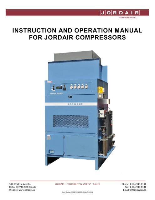
INSTRUCTION AND OPERATION MANUAL<br />
FOR JORDAIR COMPRESSORS<br />
101-7950 Huston Rd.<br />
Delta, BC V4G 1C2 Canada<br />
Website: www.jordair.ca<br />
JORDAIR – “RELIABILITY & SAFETY” - BAUER Phone: 1-604-940-8101<br />
Fax: 1-604-940-8131<br />
Email: info@jordair.ca<br />
Doc. <strong>Jordair</strong> COMPRESSOR-MANUAL-2013
JORDAIR GENERIC INSTRUCTION AND OPERATION MANUAL<br />
This <strong>Jordair</strong> Compressor Operators Manual is for your reference, the user’s safety<br />
<strong>and</strong> to ensure the correct <strong>operation</strong> of the compressor system.<br />
For the operator’s safety, it is important that this entire <strong>manual</strong> be read <strong>and</strong><br />
followed!!!<br />
WARNING!<br />
Failure to operate <strong>and</strong> maintain the compressor system according to<br />
this <strong>instruction</strong> book can result in unacceptable air quality <strong>and</strong> be<br />
hazardous to the operator. These practices will also void the warranty.<br />
GENERAL NOTE:<br />
The <strong>operation</strong>s <strong>manual</strong> is designed to cover all of the options <strong>and</strong> features<br />
available on the st<strong>and</strong>ard <strong>Jordair</strong> Compressor <strong>Inc</strong>. breathing air compressor<br />
systems. As such, it is quite normal that some of the features listed may or may not<br />
be on your specific compressor model. Please review the complete <strong>manual</strong> to<br />
familiarize yourself with all aspects of the compressor system. Be sure to pay<br />
specific attention to those items, which apply, directly to your compressor system.<br />
The Bauer compressor block <strong>manual</strong> <strong>and</strong> parts list is the supplementary <strong>manual</strong> for<br />
the specific compressor model <strong>and</strong> system.<br />
Please contact the factory for additional detailed technical clarification or any other<br />
specific information required:<br />
HEAD OFFICE AND MANUFACTURING:<br />
<strong>Jordair</strong> <strong>Compressors</strong> <strong>Inc</strong>.<br />
#101-7950 Huston Rd<br />
Delta, BC V4G 1C2<br />
Toll Free: (800) 940-8101<br />
Fax: (604) 940-8131<br />
Email: info@jordair.ca<br />
Website: www.jordair.ca<br />
All rights reserved. No part of this publication may be reproduced, distributed, or transmitted in any form or by any means, or stored in<br />
a database or retrieval system, without the prior written permission of <strong>Jordair</strong> <strong>Compressors</strong> Ltd.<br />
101-7950 Huston Rd.<br />
Delta, BC V4G 1C2 Canada<br />
Website: www.jordair.ca<br />
JORDAIR – “RELIABILITY & SAFETY” - BAUER Phone: 1-604-940-8101<br />
Fax: 1-604-940-8131<br />
Email: info@jordair.ca<br />
Doc. <strong>Jordair</strong> COMPRESSOR-MANUAL-2013
WARNING!<br />
HIGH PRESSURE UNITS<br />
Never operate a high-pressure<br />
compressor with the inter-stage or<br />
final safety relief valves removed<br />
<strong>and</strong> plugged, or if the safety<br />
valves are adjusted above the<br />
factory set range.<br />
Tampering with inter-stage relief<br />
valves can result in an<br />
“Explosion Failure” of a cylinder<br />
or cooler tubing.<br />
High pressure air has<br />
Tremendous Kinetic Energy <strong>and</strong><br />
should be treated with the utmost<br />
caution.<br />
101-7950 Huston Rd.<br />
Delta, BC V4G 1C2 Canada<br />
Website: www.jordair.ca<br />
JORDAIR – “RELIABILITY & SAFETY” - BAUER Phone: 1-604-940-8101<br />
Fax: 1-604-940-8131<br />
Email: info@jordair.ca<br />
Doc. <strong>Jordair</strong> COMPRESSOR-MANUAL-2013
TABLE OF CONTENTS<br />
Safety Facts for setting up your Compressor ............................................................. 1<br />
Preparation for Compressor Service ........................................................................... 2<br />
Intake Filters .................................................................................................................. 2<br />
Compressor Description ............................................................................................... 3<br />
Air Flow .......................................................................................................................... 3<br />
Maintenance Timetable ................................................................................................. 4<br />
Type of Oil ...................................................................................................................... 5<br />
Oil Change Procedure ................................................................................................... 5<br />
To Prepare the Compressor for Prolonged Storage ................................................... 6<br />
Reactivating the Compressor Unit ............................................................................... 6<br />
Lubrication System ....................................................................................................... 6<br />
Compressor Oil Pump Drive ......................................................................................... 7<br />
Oil Pump Drive Service ................................................................................................. 7<br />
Initial Trial Run of the Compressor .............................................................................. 7<br />
Pressure Relief Valves .................................................................................................. 8<br />
Valve Heads ................................................................................................................... 8<br />
Valve Head Maintenance ............................................................................................... 9<br />
Cylinder Removal .......................................................................................................... 9<br />
Piston Final Stage ......................................................................................................... 10<br />
Automatic Drain System ............................................................................................... 10<br />
101-7950 Huston Rd.<br />
Delta, BC V4G 1C2 Canada<br />
Website: www.jordair.ca<br />
JORDAIR – “RELIABILITY & SAFETY” - BAUER Phone: 1-604-940-8101<br />
Fax: 1-604-940-8131<br />
Email: info@jordair.ca<br />
Doc. <strong>Jordair</strong> COMPRESSOR-MANUAL-2013
Automatic Drain Operation ........................................................................................... 10<br />
Service of the Automatic Drain ............................................................................... 11-12<br />
<strong>Jordair</strong> Compressor Controls ....................................................................................... 13<br />
Manual-Off-Auto Switch ..................................................................................... 13<br />
Auto Mode ........................................................................................................... 13<br />
Start Switch ......................................................................................................... 13<br />
LOP Fault Indicator Light <strong>and</strong> Audible Alarm................................................... 13<br />
HAT Fault Indicator ............................................................................................. 14<br />
Silence Button for the Audible Alarms ............................................................. 14<br />
Power on Light .................................................................................................... 14<br />
Initial Operating Sequence ..................................................................................... 14-15<br />
Compressor Air Pressure Switch ................................................................................. 16<br />
Compressor Oil Switch ................................................................................................. 16<br />
Service of the Final Oil <strong>and</strong> Water Separator ......................................................... 17-18<br />
Service of the Pressure Maintaining Valve............................................................. 18-19<br />
Note to Operators .....................................................................................................20-21<br />
Recommended Procedures for Testing Pure Air .................................................. 22-24<br />
General Recommendations ......................................................................................... 24<br />
Filter Information for 5000 PSIG Systems .................................................................. 25<br />
Filter Information for 6000 PSIG Systems .................................................................. 26<br />
Motor Voltage <strong>and</strong> Amp Load ...................................................................................... 27<br />
Troubleshooting ...................................................................................................... 28-29<br />
Daily SCBA Log<br />
Compressor Service Log (2 Pages)<br />
SUPPLEMENTARY: Bauer Block Instruction Manual <strong>and</strong> Spare Parts Catalogue<br />
101-7950 Huston Rd.<br />
Delta, BC V4G 1C2 Canada<br />
Website: www.jordair.ca<br />
JORDAIR – “RELIABILITY & SAFETY” - BAUER Phone: 1-604-940-8101<br />
Fax: 1-604-940-8131<br />
Email: info@jordair.ca<br />
Doc. <strong>Jordair</strong> COMPRESSOR-MANUAL-2013
Safety Facts for Setting up Your Compressor<br />
Setting up in a Closed Room<br />
A compressor is an air-cooled machine, <strong>and</strong> since air under compression increases in<br />
temperature, it is imperative that the compressor be installed with adequate ventilation.<br />
<br />
<br />
<br />
<br />
<br />
<br />
The machine should be placed at least 18” away from any wall on the fan side of<br />
the compressor <strong>and</strong> 2.5 feet on the discharge air side of the compressor The 18”<br />
may be ignored if the machine is placed in front of a suitably sized opening cut<br />
into the wall to allow cooling air to flow over the compressor.<br />
Air should be available from two directions within the room, the openings in each<br />
wall being in excess of six square feet, preferably with one opening close to the floor<br />
<strong>and</strong> the other close to the ceiling.<br />
If flowing ventilation is not available, a fan must be used to remove the heated air.<br />
Follow the installation guidelines in the Bauer Compressor Installation Manual IH-E<br />
11/94<br />
The compressor should never be operated with an ambient room temperature in<br />
excess of 40°C.<br />
The air must be free of poisonous gases <strong>and</strong> exhaust gases (such as flue gases,<br />
solvent fumes, paint fumes, engine exhaust etc.)<br />
Note: When setting up a compressor station in a sub-grade or basement location,<br />
always ensure that the intake air supply is from an external location where the<br />
ambient air is as pure as possible.<br />
Warning!<br />
Do not place the compressor air intake hose in a basement window which is set<br />
below ground level or on the same level with the sidewalk. Danger to life exists due<br />
to the possible contamination from vehicle exhaust gases!<br />
Setting up in the Open Air<br />
For gasoline or diesel driven units it is important that pure air only is sourced for the<br />
compressor intake. Set up the unit in so that the engine exhaust is downstream of the wind<br />
direction, so the combustion gases are carried away from the compressor unit <strong>and</strong> the air<br />
intake. <strong>Jordair</strong> recommends the mounting of an intake hose of at least 7.5 feet in length<br />
to the compressor intake filter with pre-filter. The pre-filter is to be placed at a height of 5<br />
feet. This method of compressor set up provides a safe distance between the outlets of the<br />
exhaust gases <strong>and</strong> air the compressor intake air supply.<br />
101-7950 Huston Rd.<br />
Delta, BC V4G 1C2 Canada<br />
Website: www.jordair.ca<br />
JORDAIR – “RELIABILITY & SAFETY” - BAUER Phone: 1-604-940-8101<br />
Fax: 1-604-940-8131<br />
Email: info@jordair.ca<br />
Doc. <strong>Jordair</strong> COMPRESSOR-MANUAL-2013<br />
1
If there is a change in the wind direction, turn the unit correspondingly.<br />
Operate a unit with a diesel or gasoline engine in the open air; never operate an<br />
engine driven compressor in a room being completely or partially closed.<br />
An engine driven compressor can be operated within an enclosed or partially<br />
enclosed area if the exhaust is piped outside of the space through a wall <strong>and</strong> the<br />
compressor intake air is sourced at a high elevation away from the exhaust gas<br />
contamination.<br />
Ensure that vehicles with running engines are not within 50 meters of the intake inlet<br />
unless the compressor is integrated into the vehicle <strong>and</strong> operates off the vehicle<br />
engine or generator system.<br />
On truck mounted systems ensure the air intake is located well away <strong>and</strong> elevated<br />
above the source of the vehicle exhaust gases.<br />
Do not run the unit near an open fire (flue gases).<br />
Preparation for Compressor Service<br />
Open frame units – these compressors are readily accessible <strong>and</strong> will not require the removal<br />
of frame enclosing components for routine service.<br />
Enclosed units – the Ultra-Silent <strong>and</strong> Integra compressors require panel removal before<br />
service work is performed. Lift the latches out <strong>and</strong> turn to release the panel, <strong>and</strong> then<br />
remove the front, rear <strong>and</strong> top panels from the unit. This will expose the compressor unit for<br />
service. The lower panel must be removed to adjust the drive belts.<br />
Intake Filters & Extended Intake Piping<br />
The air intake filter is a dry paper type micron element, effective to 5-micron filtration of<br />
particulate matter. This cartridge can be easily replaced without the use of tools. If an<br />
intake extension is to be attached to the intake filter, use a short section of non-collapsible<br />
flexible hose. This flexible hose will connect the compressor to the wall mounted intake<br />
pipe. The flex hose will absorb vibration between the compressor <strong>and</strong> the air intake<br />
extension pipe. The plastic wall-mounted intake pipe is to have a minimum diameter of<br />
three inches for up to 45 feet of length. This is based on a flexible intake hose length of 5<br />
feet. The plastic intake pipe is to be increased by ½” increments in diameter for every<br />
additional 25 feet of distance from the compressor.<br />
101-7950 Huston Rd.<br />
Delta, BC V4G 1C2 Canada<br />
Website: www.jordair.ca<br />
JORDAIR – “RELIABILITY & SAFETY” - BAUER Phone: 1-604-940-8101<br />
Fax: 1-604-940-8131<br />
Email: info@jordair.ca<br />
Doc. <strong>Jordair</strong> COMPRESSOR-MANUAL-2013<br />
2
Discharge Piping<br />
All compressor installation piping is under the Provincial Boilers & Pressure Vessels<br />
jurisdiction <strong>and</strong> installed tubing <strong>and</strong> fittings must have CRN registration <strong>and</strong> be installed by<br />
a B&PV licensed <strong>and</strong> registered contractor.<br />
Compressor Description<br />
The air compressor is a multi-stage, air cooled, single acting <strong>and</strong> reciprocating unit,<br />
designed to deliver a final discharge pressure depending on the specific model of unit of<br />
5000, 6000, or 7250 PSIG. Lower pressure shut down is set on the final operating<br />
pressure switch shut down set point.<br />
Note: The st<strong>and</strong>ard design of compressor is for 5000 or 6000 PSIG service <strong>and</strong><br />
special units are offered for 7250 PSIG filling applications. Lubrication is by splash<br />
<strong>and</strong> full flow filtered oil pressure injection to the final free floating piston.<br />
The compressor operates with an optimum oil pressure range from 50 to 75 psig<br />
depending on the model. The oil pump pressure regulator on all units automatically<br />
regulates the compressor oil pressure. Note: Junior <strong>and</strong> Oceanus <strong>Compressors</strong> are<br />
splash lubricated only.<br />
Air Flow<br />
The process airflow is subjected to heat generation as part of the thermal temperature<br />
increase when air is subjected to the compression stages of the compressor. The inter-stage<br />
coolers are designed to remove most of the heat <strong>and</strong> the separators collect the<br />
accumulating moisture generated during compression. The airflow begins when the<br />
compressor crankshaft rotates <strong>and</strong> the first-stage piston draws the ambient air through the<br />
micron intake filter <strong>and</strong> the suction valve into the first stage cylinder. This air is<br />
compressed by the first stage piston <strong>and</strong> expelled through the discharge valve <strong>and</strong> travels<br />
via the inter-cooler to the second stage. It is necessary to cool the air to nearly ambient<br />
temperature to reduce component wear <strong>and</strong> prevent combustion of the lubricating oil <strong>and</strong><br />
production of carbon monoxide. The Bauer block achieves the optimum in cooling efficiency<br />
with all inter-coolers <strong>and</strong> cylinders located in the direct airflow path of the cooling fan.<br />
The air enters the second stage through the suction valve <strong>and</strong> is compressed by the<br />
piston. The compressed air after passing through the discharge valve is cooled by an<br />
inter-cooler <strong>and</strong> any oil droplets or an inter-stage separator removes liquid moisture. On the<br />
four stage compressors this process is repeated in the third stage <strong>and</strong> the air is again<br />
cooled <strong>and</strong> liquid oil <strong>and</strong> moisture is removed at a separator prior to entering the fourth<br />
101-7950 Huston Rd.<br />
Delta, BC V4G 1C2 Canada<br />
Website: www.jordair.ca<br />
JORDAIR – “RELIABILITY & SAFETY” - BAUER Phone: 1-604-940-8101<br />
Fax: 1-604-940-8131<br />
Email: info@jordair.ca<br />
Doc. <strong>Jordair</strong> COMPRESSOR-MANUAL-2013<br />
3
stage. In five stage compressors the process is repeated on the fourth stage. The<br />
compressed air leaving the final stage is cooled to approximately 5 to 8°C above ambient<br />
temperature <strong>and</strong> remaining liquids are collected in the final oil/water coalescing separator.<br />
The collected moisture <strong>and</strong> oil droplets can be drained <strong>manual</strong>ly or by an automatic drain<br />
device into the condensate collection container for <strong>manual</strong> draining of accumulated liquids.<br />
The process air is pre-cleaned to 5 microns by a micro-fibre or sintered element in the oil<br />
<strong>and</strong> water separator <strong>and</strong> passes out through a check valve. This one-way check valve stops<br />
the purified air from flowing back into the oil <strong>and</strong> water separator. The process air is then<br />
dried in a drying cartridge <strong>and</strong> purified to eliminate oil <strong>and</strong> hydrocarbons. A CO catalyst<br />
removes any CO <strong>and</strong> the activated carbon completes the process of purifying the air to the<br />
CSA breathing air st<strong>and</strong>ard.<br />
Special filters <strong>and</strong> purifications systems can be installed to remove any undesirable<br />
component in the compressed air.<br />
The final pressure-maintaining valve is set at approximately 2200 PSIG to ensure efficient<br />
<strong>operation</strong> of the filter system on 5000 PSIG compressors. On 6000 PSIG <strong>and</strong> higher<br />
compressors, the pressure maintaining valve is set at 2800 PSIG.<br />
Contact <strong>Jordair</strong> <strong>Compressors</strong> directly for specialized technical assistance<br />
on nonst<strong>and</strong>ard applications.<br />
Maintenance Timetable<br />
A logbook is an ideal means of maintaining running time <strong>and</strong> dates of service.<br />
The first oil change is recommended after reaching 25 hours of running time or within 3<br />
months, whichever occurs first. Each additional oil change is to take place after 500 hours of<br />
<strong>operation</strong> or every 6 months. (It is recommended the compressor be run for<br />
approximately 30 minutes to warm the oil prior to draining).<br />
Note: Check all mounting bolts, compressor bolts <strong>and</strong> electrical connections prior<br />
to placing a compressor in service <strong>and</strong> also at 100 hours to avoid any problems<br />
related to transport vibration or other reasons.<br />
101-7950 Huston Rd.<br />
Delta, BC V4G 1C2 Canada<br />
Website: www.jordair.ca<br />
JORDAIR – “RELIABILITY & SAFETY” - BAUER Phone: 1-604-940-8101<br />
Fax: 1-604-940-8131<br />
Email: info@jordair.ca<br />
Doc. <strong>Jordair</strong> COMPRESSOR-MANUAL-2013<br />
4
Type of Oil<br />
The use of the correct oil is necessary to maintain compressor reliability <strong>and</strong> warranty.<br />
The compression loading is over three, four or five stages, which neither stresses the oil<br />
mechanically nor creates thermal excesses. It is, however, recommended that only first<br />
class grades of oil be used. To ensure reliable compressor service <strong>and</strong> warranty, use those<br />
oils as prescribed by <strong>Jordair</strong>, which have the smallest inclination to produce carbon <strong>and</strong><br />
guarantee protection against corrosion.<br />
The recommended oil is <strong>Jordair</strong> part number J-EP-65 compressor oil. Contact <strong>Jordair</strong><br />
for an alternate oil selection if it is impractical to obtain the <strong>Jordair</strong> oil at the compressor<br />
location. Synthetic oils are also available for use in breathing air compressors to<br />
increase the operating life when the compressor is subject to heavy-duty cycles <strong>and</strong> high<br />
ambient temperature condition.<br />
Oil Change Procedure<br />
If the recommended operating hours, between changes, are not reached in six months<br />
time, the oil is to be changed to avoid internal corrosion.<br />
Remove the drain plug <strong>and</strong> open the drain valve, then drain the oil into a container for<br />
disposal. The oil is to be drained while the compressor is still warm. On compressor units<br />
with magnetic plugs, remove <strong>and</strong> clean all particulate.<br />
Note: On year 2000 <strong>and</strong> newer the oil filter also needs to be replaced.<br />
To re-fill the oil, close the valve <strong>and</strong> replace the drain plug then remove the oil cap <strong>and</strong><br />
add the oil slowly to the correct level on the sight indicator glass, older models may have<br />
an oil level dipstick.<br />
Caution:<br />
Never over-fill the compressor with oil. If the compressor is overfilled, drain the<br />
excess oil to the correct level on the sight level glass or dipstick. After oil change,<br />
open all drain valves <strong>and</strong> run the compressor unloaded until correct oil pressure<br />
is indicated on oil gauge.<br />
Start the unit <strong>and</strong> check the sight glass or oil pressure gauge to ensure the lubricating oil<br />
system is operating correctly. If the oil pressure fluctuates then bleed any air at the<br />
pressure gauge or oil regulator. Always bleed at the highest point to remove all air from the<br />
pressure lubrication system.<br />
101-7950 Huston Rd.<br />
Delta, BC V4G 1C2 Canada<br />
Website: www.jordair.ca<br />
JORDAIR – “RELIABILITY & SAFETY” - BAUER Phone: 1-604-940-8101<br />
Fax: 1-604-940-8131<br />
Email: info@jordair.ca<br />
Doc. <strong>Jordair</strong> COMPRESSOR-MANUAL-2013<br />
5
To Prepare the Compressor for Prolonged Storage<br />
First proceed as above <strong>and</strong> perform the oil change. Next, remove the intake filter<br />
housing <strong>and</strong> operate the compressor with the drain cocks open, slowly pour<br />
approximately 20 ml. of oil into the cylinder intake hole on the first stage while the interstage<br />
drain valves are open.<br />
Stop the compressor, close all drains, replace <strong>and</strong> seal the compressor intake housing.<br />
Now the compressor unit is ready for storage.<br />
Reactivating the Compressor Unit<br />
<br />
<br />
<br />
<br />
<br />
<br />
<br />
<br />
<br />
Remove the dust cap from the inlet port <strong>and</strong> replace the intake filter.<br />
Check the oil level of the compressor.<br />
Check the motor/engine according to the manufacturer’s <strong>instruction</strong>s.<br />
Only applicable for units equipped with a filter system: open the purifier <strong>and</strong> change<br />
all filter cartridges.<br />
Operate the compressor with open filling valves or outlet valve for approx. 5 minutes.<br />
Check the oil pressure on the pressure gauge. If there is any fault, check the<br />
lubrication of the compressor.<br />
After 5 minutes, close the filling valves or the outlet valve <strong>and</strong> run the unit up to final<br />
pressure or until the final pressure safety valve blows. To check the final safety valve,<br />
override the pressure switch if installed on the unit.<br />
Check the inter-pressure safety valves for leakage.<br />
Establish the cause of any fault by identifying it in the general information from the<br />
trouble–shooting table, section 19, <strong>and</strong> remedy.<br />
The compressor is now ready to return to normal service.<br />
Lubrication System (Year 2000 <strong>and</strong> newer)<br />
The final stage piston is pressure lubricated by a gear pump with a nominal pressure of<br />
50 to 75 psig. The lubricating oil is pumped through an in-line filter to the minimum<br />
pressure valve mounted on the oil pump housing. The lubricating oil is regulated <strong>and</strong><br />
injected on the lower part of the floating piston when it is in the top dead center position.<br />
The oil enters into the clearance between the floating piston <strong>and</strong> the cylinder sleeve. The<br />
high-pressure oil lubricates the piston <strong>and</strong> rings <strong>and</strong> minimizes compression blow by. The<br />
excess oil from the regulator flows back to the crankcase through a return line.<br />
101-7950 Huston Rd.<br />
Delta, BC V4G 1C2 Canada<br />
Website: www.jordair.ca<br />
JORDAIR – “RELIABILITY & SAFETY” - BAUER Phone: 1-604-940-8101<br />
Fax: 1-604-940-8131<br />
Email: info@jordair.ca<br />
Doc. <strong>Jordair</strong> COMPRESSOR-MANUAL-2013<br />
6
Lubrication System (Year 2,000 <strong>and</strong> prior)<br />
The compressor is provided with forced-feed lubrication for the 3 rd , 4 th , or 5 th stage. A Bosch<br />
injection pump is driven either by a cam lobe on the end of the crankshaft, or a camshaft<br />
driven via a V-belt or cog belt, depending on the model of compressor. It pumps oil into the<br />
pressure regulating valve at the 3 rd, 4 th or 5 th stage cylinder. The oil pressure regulator doses<br />
the oil quantity <strong>and</strong> is adjusted to the respective oil pressure. The oil pressure on these<br />
machines is adjusted to between 850 P.S.I. <strong>and</strong> 950 P.S.I. On the IK 14.11 <strong>and</strong> the IK 18.1<br />
compressors, the oil pressure is regulated by the 3 rd stage pressure <strong>and</strong> the oil pressure<br />
gauge will match the 3 rd stage pressure gauge. These compressors use an oil controller <strong>and</strong><br />
the pressure is non adjustable.<br />
The drive gear atomizes the oil <strong>and</strong> the mist lubricates the piston rings <strong>and</strong> rod bearing. The<br />
crank <strong>and</strong> main bearings are splash lubricated when the crankshaft counter weight<br />
enters the oil. The first stage cylinder receives additional lubrication from the crankcase<br />
breather pipe, which is connected to the intake port of the cylinder head.<br />
Compressor Oil Pump Drive<br />
Bauer Blocks 2000 <strong>and</strong> newer production series IK100II to IK18.1II – The compressor<br />
oil pressure of 5 bar (72 PSIG) is developed by a low revving gear type oil pump. The oil<br />
is pumped up through a final oil filter element. The filter element is to be changed every<br />
time the oil is changed to ensure correct service procedures.<br />
Oil Pump Drive Service<br />
On the 2000 <strong>and</strong> newer series compressors the oil pressure is not adjustable, if<br />
the oil pressure drops below the minimum of 30 psig, replace the minimum pressure<br />
valve as an assembly, part number 81050. If the oil pressure is still not correct then the<br />
pump must be replaced. An oil pump assembly is replaced under part number N24585.<br />
The oil filter element number for replacement is N25326. Review the specific model parts list<br />
<strong>and</strong> Bauer <strong>manual</strong> for service procedures.<br />
Initial Trial Run of the Compressor<br />
On start-up, a clicking or knocking sound will be heard from the final stage of the<br />
compressor. This is a normal condition produced by the free-floating piston tapping the<br />
guide piston in the final stage. This noise will only last until a counter pressure is built up,<br />
usually within 15 to 20 seconds. If the knocking sound continues check for inter-stage<br />
leaks, open drain cocks, or a defective automatic drain system seat or solenoid valve.<br />
Follow the repair procedures as outlined for the specific component in this <strong>manual</strong>.<br />
101-7950 Huston Rd.<br />
Delta, BC V4G 1C2 Canada<br />
Website: www.jordair.ca<br />
JORDAIR – “RELIABILITY & SAFETY” - BAUER Phone: 1-604-940-8101<br />
Fax: 1-604-940-8131<br />
Email: info@jordair.ca<br />
Doc. <strong>Jordair</strong> COMPRESSOR-MANUAL-2013<br />
7
Pressure Relief Valves<br />
As required by ASME <strong>and</strong> Boiler & Pressure Vessel, each stage of compression is provided<br />
with a spring-loaded type pressure relief valve factory set <strong>and</strong> sealed to operate at a suitable<br />
pressure to protect the individual stages of the compressor. The pressure relief valves<br />
are set high enough to allow for the momentary pressure surges, which occur as a cylinder<br />
discharges. The final discharge pressure relief valve is located on top of the final oil <strong>and</strong><br />
water separator. The final separator is usually mounted on the same part of the compressor<br />
frame as the purification chambers.<br />
Safety valves between stages protect the prior cylinder <strong>and</strong> also indicate a compressor<br />
inlet or exhaust valve malfunction when the safety valve is venting. For example: a final<br />
stage inlet or exhaust valve leak will cause excessive pressure rise between it <strong>and</strong> the<br />
preceding stage, opening the third stage relief valve. The over pressure that is built up<br />
by the final stage <strong>and</strong> not pumped onward in the system is vented safely to atmosphere<br />
by the relief valve.<br />
Warning!<br />
Never adjust inter-stage relief valves; this can cause failure of a cylinder or<br />
intercooler resulting in a possible injury or death. Only a certified company can<br />
reset relief valves.<br />
Worn or defective valves must be replaced as a complete assembly. On some compressor<br />
models, the unitized valves can be returned to the factory for repair. Contact <strong>Jordair</strong> to<br />
determine if a compressor valve is suitable for repair or must be replaced. Always replace<br />
both the inlet <strong>and</strong> exhaust valves in a compressor cylinder head as a set to avoid<br />
premature failure of the valves.<br />
Valve Heads<br />
Each cylinder has its own individual valve head complete with intake <strong>and</strong> exhaust valve.<br />
Valve heads of individual stages form the top part of the cylinder. The valves are spring<br />
loaded <strong>and</strong> operated by airflow. On the suction stroke the intake valves open <strong>and</strong> air<br />
flows into the cylinders. At the start of the compression stroke, the intake valve closes <strong>and</strong><br />
the air opens the outlet valve allowing it to flow out of the cylinder.<br />
All suction <strong>and</strong> discharge valves are spring-loaded, disc type valves consisting of a<br />
valve insert, valve spring, valve disc, <strong>and</strong> valve seat. On most models the suction<br />
valves are mounted at the bottom side of the valve head. The first stage cylinder has either<br />
a reed valve assembly between the head <strong>and</strong> cylinder or the valves installed from the<br />
topside of the valve head.<br />
101-7950 Huston Rd.<br />
Delta, BC V4G 1C2 Canada<br />
Website: www.jordair.ca<br />
JORDAIR – “RELIABILITY & SAFETY” - BAUER Phone: 1-604-940-8101<br />
Fax: 1-604-940-8131<br />
Email: info@jordair.ca<br />
Doc. <strong>Jordair</strong> COMPRESSOR-MANUAL-2013<br />
8
Valve Head Maintenance<br />
The cylinder heads should be checked after every 1000 operating hours on three stage<br />
<strong>and</strong> four stage compressors. It is important to check the security of the head bolts, cooler<br />
fittings <strong>and</strong> valve wear <strong>and</strong> cleanliness. To do so, disconnect the piping, remove the cap<br />
screws <strong>and</strong> lift off the head. Clean in a solution of mineral spirits <strong>and</strong> blow dry before<br />
removing the valves. Intake valves will be on the bottom side of the head, while<br />
exhaust valves are on the top. The exhaust valves are held in place by an Allen screw,<br />
covered by an acorn nut. Remove the acorn nut, then the Allen screw, <strong>and</strong> finally the<br />
exhaust valve.<br />
Note: Detailed valve service information for each compressor model is obtained<br />
from the factory service <strong>manual</strong> for the specific compressor type.<br />
It is usually sufficient to clean the valves with ship cloth <strong>and</strong> mineral spirits. Remove<br />
any oil, carbon, or dirt. Then clean heads with soap <strong>and</strong> water <strong>and</strong> blow dry. Heavier<br />
deposits might require the use of a glass beading machine, making sure to clean all<br />
leftover residue from the heads.<br />
The exhaust valve of the final stage on compressors can be removed by using<br />
two screwdrivers to pop it out.<br />
When re-installing the valve head, make sure that the adjusting screw on top is tightened<br />
after the valve head is torqued down on the cylinder, otherwise the stud will put too much<br />
pressure on the sealing surface of the final outlet valve. Detailed valve service is in the<br />
compressor service <strong>manual</strong>.<br />
Cylinder Removal<br />
When removing <strong>and</strong> replacing the cylinders for any reason, the pistons must come up<br />
flush with the top edge of the cylinder. If the piston projects above the cylinder, add<br />
gaskets to the cylinder base until the piston is flush.<br />
101-7950 Huston Rd.<br />
Delta, BC V4G 1C2 Canada<br />
Website: www.jordair.ca<br />
JORDAIR – “RELIABILITY & SAFETY” - BAUER Phone: 1-604-940-8101<br />
Fax: 1-604-940-8131<br />
Email: info@jordair.ca<br />
Doc. <strong>Jordair</strong> COMPRESSOR-MANUAL-2013<br />
9
Piston Final Stage<br />
First <strong>and</strong> second stage (<strong>and</strong> third stage on 4-stage machines) pistons are normal<br />
compressor types with rings. On the 1999 <strong>and</strong> older compressor blocks, the final stage<br />
piston is free floating in a piston bushing, without rings. On the 2000 <strong>and</strong> newer compressor<br />
blocks, the final stage piston is free floating with polymer rings. When replacement of the<br />
final stage is required, the piston <strong>and</strong> bushing must be replaced as a unit.<br />
Automatic Drain System<br />
Some compressor models are equipped, as a factory st<strong>and</strong>ard, with an automatic drain<br />
system for the inter-stage separators <strong>and</strong> the final oil <strong>and</strong> water separator. The automatic<br />
drain consists of an electronic timer (integrated into the PLC program), a solenoid valve,<br />
<strong>and</strong> the system drain blocks.<br />
The compressor unit is automatically drained every 15 minutes for 6 seconds, <strong>and</strong> on<br />
shutdown. This feature will ensure that the compressor will always start unloaded.<br />
The drain system is designed to be fail-safe in the open position. This feature will drain<br />
the condensate at shutdown even if the interval timer fails to operate.<br />
The o-rings <strong>and</strong> piston seals in the auto drain system are to be inspected <strong>and</strong><br />
replaced bi-annually or every 1000 hours in order to ensure reliable service.<br />
Automatic Drain Operation<br />
The operating air for the drain blocks is controlled by a solenoid that is connected by a<br />
hose from the 2nd stage separator. The timer of the PC energizes the solenoid in the<br />
closed position to direct air to actuate the pistons of the automatic drain blocks <strong>and</strong><br />
prevent draining of the inter-stage air <strong>and</strong> condensate. The solenoid valve is deenergized<br />
for 6 seconds in the open position to drain the condensate from the<br />
separators. The connection of the solenoid valve in the normally open position creates a<br />
fail-safe drain system. The compressor is to be checked for auto drain cycling every<br />
month to be sure that the drain timer is functioning correctly.<br />
101-7950 Huston Rd.<br />
Delta, BC V4G 1C2 Canada<br />
Website: www.jordair.ca<br />
JORDAIR – “RELIABILITY & SAFETY” - BAUER Phone: 1-604-940-8101<br />
Fax: 1-604-940-8131<br />
Email: info@jordair.ca<br />
Doc. <strong>Jordair</strong> COMPRESSOR-MANUAL-2013<br />
10
Service of the Automatic Drain<br />
The auto drain system is simple <strong>and</strong> easy to service. To maintain product reliability<br />
<strong>Jordair</strong> recommends that the auto drain seats, cup seals <strong>and</strong> o-rings are replaced biannually<br />
or every 1000 hours. The pistons are to be inspected <strong>and</strong> if the sealing face<br />
shows imperfections or a wear line then they are to be replaced.<br />
Valve Body<br />
Low & High Pressure Pistons<br />
Seat Lower Body<br />
O-rings, Seat & Piston Cup Seal<br />
101-7950 Huston Rd.<br />
Delta, BC V4G 1C2 Canada<br />
Website: www.jordair.ca<br />
JORDAIR – “RELIABILITY & SAFETY” - BAUER Phone: 1-604-940-8101<br />
Fax: 1-604-940-8131<br />
Email: info@jordair.ca<br />
Doc. <strong>Jordair</strong> COMPRESSOR-MANUAL-2013<br />
11
Service steps for the auto drain:<br />
1. The service of the drain is done with the exhaust manifold remaining connected to the<br />
blocks.<br />
2. Proceed to disconnect the pilot pressure line from the solenoid valve mounted on<br />
the electrical control box <strong>and</strong> the drain line from the manifold to the collection<br />
tank.<br />
3. The Allen bolts (4 to a block) are loosened <strong>and</strong> removed from the drain assembly<br />
which will provide for the removal of the top manifold exposing the valve pistons<br />
on all drains <strong>and</strong> also the lower section containing the valve seat assembly.<br />
4. This leaves the main section of the drain manifold with the block bodies mounted<br />
as a unit; the bodies can be removed to replace o-rings bi-annually.<br />
5. The seats in the lower bases can be removed <strong>and</strong> new ones installed with new o-rings.<br />
6. Push the pistons up <strong>and</strong> out of the drain bodies for inspection <strong>and</strong> seal <strong>and</strong> o-ring<br />
replacement.<br />
7. Inspect <strong>and</strong> replace all rubber parts.<br />
8. Check the pistons for any sign of wear or imperfection on the tapered sealing face,<br />
replace if wear is evident.<br />
9. After carefully inspecting all components, lubricate the working parts with silicone<br />
lubricant <strong>and</strong> assemble the drain blocks.<br />
10. When the automatic drain system is assembled: operate the compressor <strong>and</strong> check<br />
for leaks.<br />
11. While the compressor is operating at 90% of the full system operating pressure,<br />
remove the drain hose from the manifold <strong>and</strong> check that the drain pistons are seated<br />
correctly <strong>and</strong> there is no sign of leaking air.<br />
101-7950 Huston Rd.<br />
Delta, BC V4G 1C2 Canada<br />
Website: www.jordair.ca<br />
JORDAIR – “RELIABILITY & SAFETY” - BAUER Phone: 1-604-940-8101<br />
Fax: 1-604-940-8131<br />
Email: info@jordair.ca<br />
Doc. <strong>Jordair</strong> COMPRESSOR-MANUAL-2013<br />
12
<strong>Jordair</strong> Compressor Controls<br />
The compressor is controlled by an industrial PLC with control sequence in a permanent<br />
memory E-PROM. In the event of an E-PROM failure the compressor can be repaired by<br />
the replacement of the control E-PROM. Contact <strong>Jordair</strong> for any desired changes to the<br />
control system, which is done by the installation of a newly programmed E-PROM with<br />
the required control changes. The compressor can be supplied with the PLC allowing some<br />
service technician interface or password protected.<br />
Controls <strong>and</strong> Indicator Functions<br />
Note: Not all compressors will have all of the following controls<br />
Manual-Off-Auto Switch<br />
This switch controls power to the compressor system. The <strong>manual</strong> mode allows the<br />
starting of the compressor by depressing the “start” switch. The compressor will stop<br />
automatically according to the pressure switch setting or by turning the <strong>manual</strong> switch<br />
to OFF. The compressor can be re-started <strong>manual</strong>ly when the air pressure drops below<br />
the pressure switch dead b<strong>and</strong> setting.<br />
Auto Mode<br />
In this selected switch position the compressor system is controlled by the air pressure<br />
switch (PSI), which turns the compressor on <strong>and</strong> off according to preset high air<br />
pressure limits as set by <strong>Jordair</strong> or as requested by the customer. The auto re-start<br />
pressure differential is according to the pressure switch dead b<strong>and</strong>. The typical dead b<strong>and</strong><br />
range is approximately 500 PSIG. If the compressor shut down pressure is 5000 PSIG<br />
then in Auto mode the compressor will start when the pressure drops to approximately<br />
4500 PSIG.<br />
Start Switch<br />
This push type switch starts the compressor in the selected <strong>manual</strong> mode position<br />
provided the system pressure is below the pressure switch dead b<strong>and</strong> setting.<br />
LOP Fault Indicator Light <strong>and</strong> Audible Alarm<br />
A low oil pressure or an oil pressure fluctuation can cause a lubrication failure shut down<br />
condition. Check the oil level before attempting to start the compressor. In order to restart<br />
the machine the “Manual-off-Auto” switch must be turned “Off”, <strong>and</strong> then back to the<br />
selected mode of <strong>operation</strong>. This will re-set the oil pressure switch inter-lock delay timer<br />
in the control PLC. There is a 30 second delay on the compressor start cycle to allow the oil<br />
pressure to register on the pressure switch before the fault latch of the PLC is interlocked.<br />
101-7950 Huston Rd.<br />
Delta, BC V4G 1C2 Canada<br />
Website: www.jordair.ca<br />
JORDAIR – “RELIABILITY & SAFETY” - BAUER Phone: 1-604-940-8101<br />
Fax: 1-604-940-8131<br />
Email: info@jordair.ca<br />
Doc. <strong>Jordair</strong> COMPRESSOR-MANUAL-2013<br />
13
HAT Fault Indicator Light <strong>and</strong> Audible Alarm<br />
The compressor is equipped with a high air temperature sensor <strong>and</strong> shut down feature<br />
set at 275° F. The high temperature fault condition activates the light <strong>and</strong> audible alarm<br />
system in the event of a high temperature condition of the final stage of the compressor.<br />
This safety device indicates that system shutdown has occurred due to overheating of the<br />
compressor (high air temperature). To restart the machine the "Manual-Off-Auto"<br />
switch must be turned "Off", <strong>and</strong> then back to the selected mode of <strong>operation</strong>. Check<br />
the compressor carefully <strong>and</strong> ensure that it rotates easily before starting. Observe the<br />
compressor <strong>operation</strong> to find the reason for the temperature-actuated shutdown. The<br />
compressor can be started again when the unit temperature drops sufficiently to allow the<br />
switch contacts to return to the normal contact position.<br />
Important! The safety functions of the high air temperature <strong>and</strong> low oil pressure alarms<br />
<strong>and</strong> shutdown are also <strong>operation</strong>al in the “Manual” mode, thus affording full protection<br />
on <strong>manual</strong> as well as auto <strong>operation</strong>.<br />
Silence Button for the Audible Alarms<br />
The fault alarm will sound until the Manual – Off Auto switch is turned to the off position to<br />
stop the fault alarm. This will reset the audible alarm feature of the control system.<br />
Power on Light<br />
The electrical supply power light indicator is on in both <strong>manual</strong> <strong>and</strong> auto mode. If the<br />
light is on it indicates that there is power into the starter of the compressor unit. The<br />
power on light confirms the compressor is energized <strong>and</strong> depending on the <strong>operation</strong>al<br />
switch selection mode the compressor may start at any time.<br />
Initial Operating Sequence<br />
1. Place the “Manual-Off-Auto” switch in “Off” position.<br />
2. Connect the supply power at the correct voltage, from the customer’s fused disconnect<br />
switch. This switch is to be visible from the compressor <strong>and</strong> to have clear access in<br />
an emergency in accordance with Canadian Electrical codes. Be sure to install a<br />
lockable switch to ensure the compressor can be locked out electrically during service<br />
<strong>and</strong> maintenance procedures.<br />
3. Engage the disconnect switch <strong>and</strong> supply power to the compressor, check that the<br />
unit has power as indicated by the power-on light. Turn the selector switch to <strong>manual</strong><br />
<strong>and</strong> push the start button to momentarily bump the compressor to check that the<br />
rotation is correct. All <strong>Jordair</strong> compressors rotate in a counter clockwise direction<br />
when viewed from the drive pulley side.<br />
101-7950 Huston Rd.<br />
Delta, BC V4G 1C2 Canada<br />
Website: www.jordair.ca<br />
JORDAIR – “RELIABILITY & SAFETY” - BAUER Phone: 1-604-940-8101<br />
Fax: 1-604-940-8131<br />
Email: info@jordair.ca<br />
Doc. <strong>Jordair</strong> COMPRESSOR-MANUAL-2013<br />
14
Note: The Fan blows the cooling air across the compressor block <strong>and</strong> coolers<br />
exhausting the heated air on the opposite side to the flywheel.<br />
Caution! <strong>Inc</strong>orrect rotation will result in a premature compressor failure due to a<br />
higher overall machine temperature.<br />
4. Start the compressor in either Auto or Manual mode. Current will flow through the<br />
PSI air pressure switch. This will energize the motor starter (M1), the elapsed timer<br />
meter (ETM), the purge timer (PTR) <strong>and</strong> the low oil pressure timer (TR1). The<br />
power continues through contacts 95 <strong>and</strong> 96 of the overload relay to the grounded<br />
side of the transformer T1 secondary. When the starter M1 energizes, auxiliary<br />
contacts 13 <strong>and</strong> 14 close, locking the system in the operating condition.<br />
Note A: The Air Pressure switch, (PSI), is wired so that it is normally closed, <strong>and</strong><br />
opens on rising pressure. The pressure switch (PSI) is active in both <strong>manual</strong> <strong>and</strong> auto<br />
circuits so that the system shuts down at the preset final air pressure.<br />
Note B: The oil pressure delay timer (TR1) will time out after a preset time<br />
period of 30 seconds <strong>and</strong> if the oil pressure is normal, (70 psig nominal), the<br />
compressor will continue to run normally. If the oil pressure drops to 45 PSIG, it<br />
closes the normally open contacts on (PS2 - the oil pressure switch), which turns on<br />
the (LOP) indicator light <strong>and</strong> audible alarm <strong>and</strong> shuts the compressor down.<br />
Note C: The temperature switch is wired normally open <strong>and</strong> closes on rising<br />
temperature, which turns on the high temperature indicator light <strong>and</strong> audible alarm<br />
<strong>and</strong> shuts the compressor down.<br />
Note D: To re-start the system after a low oil, high temperature, or any safety<br />
shutdown <strong>and</strong> lockout: re-set the “Manual-Auto” switch to “Off”, <strong>and</strong> then back to<br />
either <strong>manual</strong> or auto to start the compressor.<br />
101-7950 Huston Rd.<br />
Delta, BC V4G 1C2 Canada<br />
Website: www.jordair.ca<br />
JORDAIR – “RELIABILITY & SAFETY” - BAUER Phone: 1-604-940-8101<br />
Fax: 1-604-940-8131<br />
Email: info@jordair.ca<br />
Doc. <strong>Jordair</strong> COMPRESSOR-MANUAL-2013<br />
15
Compressor Air Pressure Switch<br />
The start-up <strong>and</strong> shutdown of the compressor is controlled through the air pressure<br />
switch (PS1). If the compressor air switch requires adjustment, use the following<br />
procedures:<br />
1. Start compressor <strong>and</strong> run it until the unit shuts down.<br />
2. Release the pressure from the compressor system to a point that the compressor<br />
starts in the auto mode.<br />
3. Remove the cover of the pressure switch.<br />
4. Note the pressure <strong>and</strong> rotate the adjusting screw on the pressure switch onehalf<br />
turn clock-wise to increase the pressure setting, or counter-clockwise to<br />
decrease the setting. Repeat Step 1.<br />
5. Repeat Step No. 4 until desired shutdown pressure setting is reached.<br />
Note: The only apparent difference between the air switch <strong>and</strong> the oil switch is the pressure<br />
rating <strong>and</strong> the high-pressure switch has a stainless steel sensor <strong>and</strong> connecting tube. The<br />
oil switch sensor is brass <strong>and</strong> the oil line is a flexible hose.<br />
Compressor Oil Switch<br />
Occasionally oil pressure switches may require re-adjustment due to spring set from time,<br />
vibration or other factors encountered in normal use. Oil pressure switch settings are to be<br />
checked annually to ensure the safety shutdown is functioning correctly.<br />
Re-adjustment is as follows:<br />
1. Use a multi-meter across the switch contacts to verify the low oil set pressure.<br />
2. Start the compressor <strong>and</strong> operate for one minute to allow the oil pressure to<br />
stabilize then shut down.<br />
3. Start the compressor <strong>and</strong> note the pressure on the gauge when the contacts<br />
open on the switch. If required correct the contact opening pressure.<br />
101-7950 Huston Rd.<br />
Delta, BC V4G 1C2 Canada<br />
Website: www.jordair.ca<br />
JORDAIR – “RELIABILITY & SAFETY” - BAUER Phone: 1-604-940-8101<br />
Fax: 1-604-940-8131<br />
Email: info@jordair.ca<br />
Doc. <strong>Jordair</strong> COMPRESSOR-MANUAL-2013<br />
16
Service of the Final Oil <strong>and</strong> Water Separator<br />
The final separator contains a micro-fibre or sintered element type cartridge, which<br />
separates the free water <strong>and</strong> oil droplets causing them to collect in the bottom section<br />
of the chamber. The process air stream enters a tube in the centre of the element <strong>and</strong><br />
passes through a number of side holes. The air then flows through the micro-fibre or sintered<br />
metal element into the open area of the chamber. The oil <strong>and</strong> water droplets are collected by<br />
the element <strong>and</strong> move down its fibre structure to drip off <strong>and</strong> collect in the chamber base.<br />
The air is also cooling <strong>and</strong> moisture is collecting on the chamber walls. The accumulating<br />
liquids are drained to collection, either <strong>manual</strong>ly or by an automatic drain device. The<br />
separator micro-fibre element is to be changed at the same intervals as the purification<br />
cartridges; sintered elements are to be changed every 12 months.<br />
Sintered Element<br />
Micro-Fibre Element<br />
101-7950 Huston Rd.<br />
Delta, BC V4G 1C2 Canada<br />
Website: www.jordair.ca<br />
JORDAIR – “RELIABILITY & SAFETY” - BAUER Phone: 1-604-940-8101<br />
Fax: 1-604-940-8131<br />
Email: info@jordair.ca<br />
Doc. <strong>Jordair</strong> COMPRESSOR-MANUAL-2013<br />
17
Changing of the element:<br />
1. Be sure to vent all pressure from the compressor system before attempting to<br />
service the separator.<br />
2. Disconnect the tubing on both sides of the top cap. Remove the top cap from<br />
the chamber to expose the element <strong>and</strong> stem assembly. The Bauer sintered<br />
element is to be cleaned every 3 to 6 months <strong>and</strong> replaced once a year.<br />
3. Remove the bottom plastic retaining plate <strong>and</strong> change the micro-fiber<br />
element; it is to be changed according to the correct hours of use or every 6<br />
months as specified by <strong>Jordair</strong> in accordance with the CSA requirements for<br />
correct service of breathing air systems.<br />
4. Change the o-ring <strong>and</strong> back up rings on the chamber cap.<br />
5. Be sure to lubricate the o-rings, the sealing surface of the chamber <strong>and</strong> the<br />
threads before installing the cap in the separator or the barrel onto the<br />
base cap.<br />
6. Install the cap <strong>and</strong> return it to the correct position to the match tubing.<br />
7. After completing the cartridge changes start the compressor <strong>and</strong> check the<br />
system for any leaks.<br />
Service of the Pressure Maintaining Valve<br />
The pressure-maintaining valve of the filter system provides a backpressure to ensure<br />
the highest degree of moisture removal efficiency is achieved by the desiccant in the<br />
purification bed. The desiccant reaches the highest level of efficiency at operating<br />
pressures above 2000 PSIG. The normal set pressure for the pressure-maintaining<br />
valve in a 5000 PSIG <strong>and</strong> higher filter system is 2800 PSIG. To provide optimum<br />
service of this valve the seat <strong>and</strong> o-rings are to be replaced once a year.<br />
101-7950 Huston Rd.<br />
Delta, BC V4G 1C2 Canada<br />
Website: www.jordair.ca<br />
JORDAIR – “RELIABILITY & SAFETY” - BAUER Phone: 1-604-940-8101<br />
Fax: 1-604-940-8131<br />
Email: info@jordair.ca<br />
Doc. <strong>Jordair</strong> COMPRESSOR-MANUAL-2013<br />
18
Support Spring Retainer Lock Adjuster<br />
Seat Body Spring Stem Nozzle<br />
1. To service the valve slowly vent the air in the purification system via the vent valve<br />
mounted on the side of the pressure-maintaining valve.<br />
2. Turn the upper adjusting screw counter clockwise <strong>and</strong> remove from the upper section<br />
of the valve.<br />
3. Remove the spring retainer from the body of the valve to allow removal of the stem<br />
<strong>and</strong> seat assembly, replace the seat <strong>and</strong> o-ring on the stem assembly.<br />
4. The body is to be unscrewed from the connecting fitting to allow removal of the<br />
stainless seat nozzle assembly so that the o-ring can be replaced. Check the nozzle<br />
for any imperfections <strong>and</strong> replace if damaged.<br />
5. Re-assemble the valve <strong>and</strong> using a pressure gauge connected to the side port set<br />
the valve to open at 2800 PSIG.<br />
Caution:<br />
Do not set above 2800 PSIG or tighten until the valve will not open.<br />
Always release all pressure before repairing any tubing or system air leaks.<br />
101-7950 Huston Rd.<br />
Delta, BC V4G 1C2 Canada<br />
Website: www.jordair.ca<br />
JORDAIR – “RELIABILITY & SAFETY” - BAUER Phone: 1-604-940-8101<br />
Fax: 1-604-940-8131<br />
Email: info@jordair.ca<br />
Doc. <strong>Jordair</strong> COMPRESSOR-MANUAL-2013<br />
19
April 15, 2006<br />
To: All Operators of Bauer/JMAR <strong>and</strong> <strong>Jordair</strong> Breathing Air <strong>Compressors</strong><br />
<strong>Jordair</strong> is the exclusive Canadian Agent for Bauer Kompressoren GmbH for the Sales,<br />
Assembly <strong>and</strong> Service of breathing air systems with Bauer compressor blocks. Please<br />
refer to the Bauer “Authorization Letter” dated April 03, 2006 in accordance with the CSA<br />
st<strong>and</strong>ard for breathing air.<br />
<strong>Jordair</strong> as an accredited ISO 9001-2008 company <strong>and</strong> follows the recommendations of<br />
CSA St<strong>and</strong>ard CAN/CSA Z180.1-00 for Breathing Air to ensure the highest degree of<br />
safety <strong>and</strong> reliability in all <strong>Jordair</strong>/Bauer breathing air systems.<br />
The following is the <strong>Jordair</strong> <strong>Compressors</strong> <strong>Inc</strong>. policy <strong>and</strong> factory requirements for<br />
authorized service technicians, which became effective May 1st 2002.<br />
<br />
<br />
<br />
<br />
Only <strong>Jordair</strong> <strong>Compressors</strong> <strong>Inc</strong>. factory trained service technicians holding<br />
current training certificates are authorized by <strong>Jordair</strong> to work on <strong>Jordair</strong>,<br />
Bauer or JMAR compressor systems operating in Canada.<br />
<strong>Jordair</strong> technical service representatives are required to participate in a<br />
refresher course every 2-year’s in order to have a valid certificate.<br />
Any unauthorized service of <strong>Jordair</strong>/Bauer breathing air systems will result<br />
in a void of any <strong>and</strong> all warranty. See the Bauer “Authorization Letter”.<br />
Any compressor system using a Bauer block <strong>and</strong> assembled in Canada<br />
other than by <strong>Jordair</strong> <strong>Compressors</strong> <strong>Inc</strong>. is void of any <strong>and</strong> all <strong>Jordair</strong> <strong>and</strong><br />
Bauer Kompressoren Gmbh. Factory warranty.<br />
The implementation of factory recommended service intervals as per CSA:<br />
CSA St<strong>and</strong>ard Clause 5.7 “The installation, inspection, testing, <strong>operation</strong>, maintenance,<br />
<strong>and</strong> repair of components of a compressed breathing air system shall be performed as<br />
specified by the manufacturers of the components of the compressed breathing air<br />
system”.<br />
101-7950 Huston Rd.<br />
Delta, BC V4G 1C2 Canada<br />
Website: www.jordair.ca<br />
JORDAIR – “RELIABILITY & SAFETY” - BAUER Phone: 1-604-940-8101<br />
Fax: 1-604-940-8131<br />
Email: info@jordair.ca<br />
Doc. <strong>Jordair</strong> COMPRESSOR-MANUAL-2013<br />
20
The proper service of these ultra-high pressure systems will ensure operator safety,<br />
compressor reliability <strong>and</strong> the highest quality of breathing air. In order to comply with the<br />
current CSA st<strong>and</strong>ard the compressor system must be checked <strong>and</strong> serviced at regular<br />
intervals by factory certified technicians as specified in the CSA st<strong>and</strong>ard.<br />
CSA St<strong>and</strong>ard Clause 7.1 General, “Air compressors shall be installed, maintained, <strong>and</strong><br />
operated in accordance with the manufacturer’s <strong>instruction</strong>s”.<br />
As the manufacturer <strong>and</strong> Exclusive Canadian Agent for Bauer Kompressoren Gmbh.,<br />
<strong>Jordair</strong> has implemented the following procedures for the safe <strong>operation</strong> <strong>and</strong> qualified<br />
technical service of the breathing air products supplied.<br />
All <strong>Jordair</strong>/Bauer/JMAR compressor systems producing breathing air except<br />
with a Securus Moisture Monitor are to have the purification cartridges<br />
changed every 6-month even if the life span of the cartridge in operating<br />
hours has not been reached.<br />
Purification systems supplied with a Securus Moisture Monitor can be<br />
operated beyond six months <strong>and</strong> up to one year or until the yellow warning<br />
light comes on, whichever comes first.<br />
To guarantee air purity st<strong>and</strong>ards <strong>and</strong> warrantee requirements only original<br />
<strong>Jordair</strong> or Bauer purification cartridges will be used in the<br />
<strong>Jordair</strong>/Bauer/JMAR breathing air systems.<br />
The compressor system will be checked once a year for pressure leaks <strong>and</strong><br />
the minimum service will include a filter <strong>and</strong> oil change.<br />
Only <strong>Jordair</strong> factory certified technicians with current certificates are<br />
authorized to service <strong>Jordair</strong>/Bauer/JMAR systems in Canada.<br />
For any further clarification in this regards contact:<br />
Mr. Jeremy Row<strong>and</strong><br />
Managing Director<br />
<strong>Jordair</strong> <strong>Compressors</strong> <strong>Inc</strong><br />
Email jrow<strong>and</strong>@jordair.ca<br />
Tel: 604-589-8189 ext. 306<br />
Fax: 604-589-8131<br />
101-7950 Huston Rd.<br />
Delta, BC V4G 1C2 Canada<br />
Website: www.jordair.ca<br />
JORDAIR – “RELIABILITY & SAFETY” - BAUER Phone: 1-604-940-8101<br />
Fax: 1-604-940-8131<br />
Email: info@jordair.ca<br />
Doc. <strong>Jordair</strong> COMPRESSOR-MANUAL-2013<br />
21
RECOMMENDED PROCEDURE FOR TESTING PURIFIED AIR<br />
The testing of high pressure breathing air can often result in a failure to meet the CSA st<strong>and</strong>ard<br />
unless procedures are followed to avoid obtaining inaccurate results. There are four factors that are<br />
often found that can lead to an incorrect test of the air sample. If the sample is not taken in the most<br />
controlled manner an air test can fail on one or more of these. The main failure reasons are listed<br />
below <strong>and</strong> the sample method is provided to assist the technician to avoid receiving an incorrect test<br />
result when complying with the current <strong>and</strong> (NEW pending CSA breathing Air St<strong>and</strong>ard CAN/CSA-<br />
Z180.1-09).<br />
1. High Moisture: this can occur if the test cylinder has not been properly controlled or purged; a<br />
long synthetic sample hose will raise dew point.<br />
2. High Carbon Dioxide: this condition is normally due to high atmospheric levels of CO 2 from local<br />
industry. If the condition is a normal occurrence then a CO 2 removal inlet scrubber or a CO 2<br />
removing high pressure chamber must be added to the compressor. Ensuring a clean source of<br />
the compressor fresh air intake away from any potential source of CO or CO2 contamination will<br />
help to avoid failed test results.<br />
3. High Oxygen: this is an unusual test failure <strong>and</strong> it will occur with a new drying/purifying cartridge<br />
change out. If the test is done with very little compressor running time prior to taking the air<br />
sample the molecular sieve bed will adsorb nitrogen <strong>and</strong> increase the oxygen content of the air.<br />
This is a short-term effect <strong>and</strong> stabilizes once the compressor has run for 60 minutes or longer<br />
<strong>and</strong> the cartridge purged. See air test procedures.<br />
4. Test Equipment Calibration: this is the least common reason for a test failure. The testing lab<br />
must ensure that the equipment is correctly calibrated. Always use a recognized <strong>and</strong> accredited<br />
air test facility for the CSA air testing.<br />
PLEASE NOTE: The nature of the air stream adsorbing desiccant <strong>and</strong> the other cartridge materials is<br />
they will initially store <strong>and</strong> release various gases (O2 & CO2) back into the air stream unless the<br />
system is purged.<br />
In order to have an accurate test the following procedures will correct for these physical properties<br />
of the cartridge materials <strong>and</strong> help to ensure accurate test results.<br />
101-7950 Huston Rd.<br />
Delta, BC V4G 1C2 Canada<br />
Website: www.jordair.ca<br />
JORDAIR – “RELIABILITY & SAFETY” - BAUER Phone: 1-604-940-8101<br />
Fax: 1-604-940-8131<br />
Email: info@jordair.ca<br />
Doc. <strong>Jordair</strong> AIR-TEST-PROCEDURE-2013<br />
22
AIR TEST PROCEDURES:<br />
<br />
<br />
<br />
<br />
<br />
<br />
<br />
<br />
<br />
<br />
<br />
Follow the manufacturer’s recommended procedure for the filter change.<br />
Check the setting of the Pressure Maintaining Valve (PMV) <strong>and</strong> ensure it is set at 1800 PSIG to<br />
2500 PSIG to provide efficient adsorption of moisture <strong>and</strong> other impurities by the filter cartridge.<br />
Operate the compressor for 90 to 120 minutes before proceeding with the air test.<br />
In order to balance the new cartridge the filter system must be depressurized to about 200 PSIG<br />
three times to release the retained O2 <strong>and</strong> CO2 from within the desiccant cell structure.<br />
After 60 minutes of <strong>operation</strong> slowly open the lower vent valve on the PMV valve <strong>and</strong> bleed out<br />
the pressure in the filter system. This must be done slowly to avoid physical damage to the filter<br />
media due to rapid depressurization of the system.<br />
To avoid any issues of rapid decompression of the filter system it is prudent to install an orifice<br />
up-stream of the vent valve.<br />
Close the valve <strong>and</strong> allow the unit to come up to pressure, repeat this twice more to ensure any<br />
adsorbed O2 or CO2 has come out of the adsorbing materials.<br />
Connect the sample cylinder directly to the compressor discharge point located after the filter<br />
system. Using a stainless steel connecting line to the sample cylinder will ensure the most<br />
accurate test results. A long length of high-pressure flex hose can affect the moisture content of<br />
the air due to moisture migration into the material.<br />
Follow the accredited laboratory’s procedure for filling the sample cylinder. When using another<br />
sample cylinder, it is safe practice to purge <strong>and</strong> leave a positive pressure of 200 PSIG in the<br />
sample cylinder before taking the actual test sample. The positive pressure of 200 PSIG will avoid<br />
any atmospheric moisture entering the cylinder during the purging process.<br />
Now the system is ready <strong>and</strong> the test sample can be taken with the confidence that it will be<br />
accurate <strong>and</strong> provide the desired test results.<br />
Fill the test cylinder <strong>and</strong> send it to the testing lab. Best test results will be achieved by using the<br />
air test cylinder supplied by the designated Lab.<br />
101-7950 Huston Rd.<br />
Delta, BC V4G 1C2 Canada<br />
Website: www.jordair.ca<br />
JORDAIR – “RELIABILITY & SAFETY” - BAUER Phone: 1-604-940-8101<br />
Fax: 1-604-940-8131<br />
Email: info@jordair.ca<br />
Doc. <strong>Jordair</strong> AIR-TEST-PROCEDURE-2013<br />
23
GENERAL RECOMMENDATIONS:<br />
CSA has recommendations for ensuring the <strong>operation</strong> of a safe high pressure breathing air system.<br />
Please obtain a copy of the current st<strong>and</strong>ard to ensure your system complies with all local <strong>and</strong><br />
federal agencies. Compliance with the Provincial Boiler <strong>and</strong> Pressure Vessels Department <strong>and</strong> the<br />
Worker Safety Department is a part of the CSA st<strong>and</strong>ard.<br />
<br />
<br />
<br />
<br />
<br />
<br />
<br />
All operators of high pressure breathing air systems are to be trained thoroughly to follow correct<br />
procedures for the h<strong>and</strong>ling <strong>and</strong> recharging of SCBA cylinders. All operator/service training is to<br />
be done by a certified representative for the equipment installed.<br />
<strong>Jordair</strong> recommends that all operators <strong>and</strong> service persons should attend a refresher course<br />
every 2-years to remain current <strong>and</strong> learn any new regulations or safety updates.<br />
Supplementary to the CSA required 6 month air test, <strong>Jordair</strong> recommends an air sample tube test<br />
is taken of the air system every 3 months. This simple test will ensure that the breathing air<br />
within the <strong>operation</strong>al period of the cartridge is meeting the CSA st<strong>and</strong>ard right up to the change<br />
out of the cartridge. This tube test method can be done more often if desired.<br />
The Bauer Air test kit available from <strong>Jordair</strong> will provide this level of safety <strong>and</strong> operator security<br />
during the full cartridge life. The kit comes with a full selection of sampling tubes.<br />
Removal of a filter cartridge to check a litmus color strip supplied on some manufactures filter<br />
cartridges is not recommended. The process of opening the chamber <strong>and</strong> removal of the<br />
cartridge will contaminate the inside of the chamber with moisture <strong>and</strong> will affect air quality.<br />
High pressure 4.5 SCBA cylinders <strong>and</strong> 5000 PSIG as well as 6000 PSIG systems require factory<br />
certified, properly trained operators <strong>and</strong> technical service people to ensure safe filling of SCBA<br />
cylinders. See the CSA st<strong>and</strong>ard.<br />
There is no method to control the ambient air to a compressor. The CSA st<strong>and</strong>ard states all diesel<br />
<strong>and</strong> gasoline units shall be equipped with a CO monitoring system <strong>and</strong> alarm feature. The CSA<br />
st<strong>and</strong>ard also states that electric drive compressors are to be equipped with a CO monitor with<br />
alarm <strong>and</strong> unit shut down feature, unless the operator can be 100% assured that CO cannot enter<br />
the intake of the compressor.<br />
101-7950 Huston Rd.<br />
Delta, BC V4G 1C2 Canada<br />
Website: www.jordair.ca<br />
JORDAIR – “RELIABILITY & SAFETY” - BAUER Phone: 1-604-940-8101<br />
Fax: 1-604-940-8131<br />
Email: info@jordair.ca<br />
Doc. <strong>Jordair</strong> AIR-TEST-PROCEDURE-2013<br />
24
5300 PSIG FILTER SYSTEMS<br />
J O R D A I R<br />
COMPRESSORS INC.<br />
COMPRESSOR<br />
MODEL<br />
STANDARD<br />
FILTER SYSTEM<br />
SEPARATOR FILTER CAPACITY FLOW-RATE MAXIMUM<br />
CHAMBER CARTRIDGE CHAMBER CARTRIDGE VOLUME TIME SCFM SCFH<br />
FT 3 HOURS<br />
JUNIOR P21 77159 NA NA 59183 2750 4.5 10 600<br />
OCEANUS P21 77159 NA NA 59183 2750 4.5 10 600<br />
IK100-F07 St<strong>and</strong>ard JBP41-6300-4 JS-6000-708 FC-708-SE JBPF-6300-22 67224 33,800 80 7 420<br />
Silent JBP41-6300-4S JS-6000-708 FC-708-SE JBPF-6300-22S 61687 42,100 100 7 420<br />
IK120-F07 St<strong>and</strong>ard JBP41-6300-4 JS-6000-708 FC-708-SE JBPF-6300-22 67224 33,800 53 10.5 630<br />
Silent JBP41-6300-4S JS-6000-708 FC-708-SE JBPF-6300-22S 61687 42,100 66 10.5 630<br />
IK121 St<strong>and</strong>ard JBP41-6300-4 JS-6000-708 FC-708-SE JBPF-6300-22 67224 33,800 45 12.5 750<br />
Silent JBP41-6300-4S JS-6000-708 FC-708-SE JBPF-6300-22S 61687 42,100 56 12.5 750<br />
IK12.14-F06 (IK12) St<strong>and</strong>ard JBP41-6300-4 JS-6000-708 FC-708-SE JBPF-6300-22 67224 33,800 49 11.5 690<br />
Silent JBP41-6300-4S JS-6000-708 FC-708-SE JBPF-6300-22S 61687 42,100 61 11.5 690<br />
IK12.14-F06 St<strong>and</strong>ard JBP41-6300-4 JS-6000-708 FC-708-SE JBPF-6300-22 67224 33,800 37 15.1 906<br />
Silent JBP41-6300-4S JS-6000-708 FC-708-SE JBPF-6300-22S 61687 42,100 46 15.1 906<br />
IK15.1 II St<strong>and</strong>ard JBP61-6300-4 JS-6000-1008 FC-1008-SE JBPF-6300-32 58827 52,500 35 24.4 1464<br />
Silent JBP61-6300-4S JS-6000-1008 FC-1008-SE JBPF-6300-32S 60037 64,000 43 24.4 1464<br />
IK150 II St<strong>and</strong>ard JBP61-6300-4 JS-6000-1008 FC-1008-SE JBPF-6300-32 58827 52,500 31 28.1 1686<br />
Silent JBP61-6300-4S JS-6000-1008 FC-1008-SE JBPF-6300-32S 60037 64,000 38 28.1 1686<br />
IK180 II St<strong>and</strong>ard JBP81-6300-4 JS-6000-1008 FC-1008-SE JBPF-6300-32 58825 113,000 52 35.7 2142<br />
JBPF-6300-32 58827<br />
Silent JBP81-6300-4S JS-6000-1008 FC-1008-SE JBPF-6300-32 58825 140,000 65 35.7 2142<br />
JBPF-6300-32S 60037<br />
IK22.0 St<strong>and</strong>ard JBP91-6300-4 JS-6000-1008 FC-1008-SE JBPF-6300-32 58825 173,000 62 46.6 2796<br />
JBPF-6300-32 58825<br />
JBPF-6300-32 58827<br />
Silent JBP91-6300-4S JS-6000-1008 FC-1008-SE JBPF-6300-32 58825 215,000 76 46.6 2796<br />
JBPF-6300-32 58825<br />
JBPF-6300-32S 60037<br />
THE OIL REMOVAL ELEMENT #FC-708-SE OR FC-1008-SE IS TO BE CHANGED WITH THE PURIFICATION CARTRIDGES.<br />
THE SECURUS MONITOR IS AVAILABLE FROM P41.<br />
TO CONVERT A STANDARD P SYSTEM TO SECURUS REQUIRES<br />
101-7950 Huston Rd.<br />
Delta, BC V4G 1C2 Canada<br />
Website: www.jordair.ca<br />
JORDAIR – “RELIABILITY & SAFETY” - BAUER Phone: 1-604-940-8101<br />
Fax: 1-604-940-8131<br />
Email: info@jordair.ca<br />
Doc. <strong>Jordair</strong> 5K-6K-FILTERS-2013<br />
25
J O R D A I R<br />
COMPRESSORS INC.<br />
6300 PSIG FILTER SYSTEMS<br />
COMPRESSOR<br />
MODEL<br />
STANDARD<br />
FILTER SYSTEM<br />
SEPARATOR FILTER CAPACITY FLOW-RATE MAXIMUM<br />
CHAMBER CARTRIDGE CHAMBER CARTRIDGE VOLUME TIME SCFM SCFH<br />
FT 3<br />
HOURS<br />
IK12.14-F06 (IK12) JBP41-6300-4 JS-6000-708 FC-708-SE JBPF-6300-22 67224 33,800 49 11.5 690<br />
JBP41-6300-4S JS-6000-708 FC-708-SE JBPF-6300-22-S 61687 42,100 61 11.5 690<br />
IK12.14-F06 JBP41-6300-4 JS-6000-708 FC-708-SE JBPF-6300-22 67224 33,800 37 15.1 906<br />
JBP41-6300-4S JS-6000-708 FC-708-SE JBPF-6300-22-S 61687 42,100 46 15.1 906<br />
IK15.1 II JBP61-6300-4 JS-6000-1008 FC-1008-SE JBPF-6300-32 58827 52,500 37 23.1 1386<br />
JBP61-6300-4S JS-6000-1008 FC-1008-SE JBPF-6300-32-S 60037 64,000 46 23.1 1386<br />
IK18.1 II JBP61-6300-4 JS-6000-1008 FC-1008-SE JBPF-6300-32 58827 52,500 27 31.5 1890<br />
JBP61-6300-4S JS-6000-1008 FC-1008-SE JBPF-6300-32-S 60037 64,000 33 31.5 1890<br />
IK18.1 II Integra JBP81-6300-4S JS-6000-1008 FC-1008-SE JBPF-6300-32 58827 113,000 59 31.5 1890<br />
JBPF-6300-32-S 60037<br />
IK22.0-420 JBP91-6300-4 JS-6000-1008 FC-1008-SE JBPF-6300-32 58825 173,000 62 46.6 2796<br />
JBPF-6300-32 58825<br />
JBPF-6300-32 58827<br />
JBP91-6300-4S JS-6000-1008 FC-1008-SE JBPF-6300-32 58825 215,000 76 46.6 2796<br />
JBPF-6300-32 58825<br />
JBPF-6300-32-S 60037<br />
THE OIL REMOVAL ELEMENT #FC-708-SE OR FC-1008-SE IS TO BE CHANGED WITH THE PURIFICATION CARTRIDGES.<br />
THE SECURUS MONITOR IS AVAILABLE FROM P41.<br />
TO CONVERT A STANDARD P SYSTEM TO SECURUS REQUIRES<br />
101-7950 Huston Rd.<br />
Delta, BC V4G 1C2 Canada<br />
Website: www.jordair.ca<br />
JORDAIR – “RELIABILITY & SAFETY” - BAUER Phone: 1-604-940-8101<br />
Fax: 1-604-940-8131<br />
Email: info@jordair.ca<br />
Doc. <strong>Jordair</strong> 5K-6K-FILTERS-2013<br />
26
Motor Voltage <strong>and</strong> Amp Load<br />
Single phase AC Motors Full-Load Current in Amperes (see Notes (1) to (4))<br />
HP Rating 115 V 230 V<br />
1/6 4.4 2.2<br />
1/4 5.8 2.9<br />
1/3 7.2 3.6<br />
1/2 9.8 4.9<br />
3/4 13.8 6.9<br />
1 16 8<br />
1 1/2 20 10<br />
2 24 12<br />
3 34 17<br />
5 56 28<br />
7 1/2 80 40<br />
10 100 50<br />
Notes:<br />
1. For full-load currents of 208 <strong>and</strong> 200 V motors, increase the corresponding 230 V motor full-load current by 10 <strong>and</strong><br />
15% respectively.<br />
2. These values of motor full-load current are to be used as guides only. Where exact values are requires (e.g., for<br />
motor protection), always use those appearing on the motor nameplate.<br />
3. These values of full-load current are for motors running at usual speeds <strong>and</strong> motors with normal torque<br />
characteristics. Motors built for especially low speeds or high torques may have higher full-load currents, <strong>and</strong> multi<br />
speed motors will have full-load current varying with speed, in which case the nameplate current ratings shall be<br />
used.<br />
4. The voltages listed are rated motor voltages. Corresponding Nominal System Voltages are 120 <strong>and</strong> 240 V. Refer to<br />
CSA St<strong>and</strong>ard CAN3-C235-M83, Preferred Voltage Level for AC Systems, 0 to 50,000 volts.<br />
Three-phase AC Motors Full-Load Current in Amperes<br />
Induction Type, Squirrel Cage <strong>and</strong> Wound Rotor<br />
HP Rating 115 V 230 V 460 V 575 V 2300 V<br />
1/2 4 2 1 0.8<br />
1/4 5.6 2.8 1.4 1.1<br />
1 7.2 3.6 1.8 1.4<br />
1 1/2 10.4 5.2 2.6 2.1<br />
2 13.6 6.8 3.4 2.7<br />
3 9.6 4.8 3.9<br />
5 15.2 7.6 6.1<br />
7 1/2 22 11 9<br />
10 28 14 11<br />
15 42 21 17<br />
20 54 27 22<br />
25 68 34 27<br />
30 80 40 32<br />
40 104 52 41<br />
50 130 65 52<br />
60 154 77 62 16<br />
75 192 96 77 20<br />
100 248 124 99 26<br />
101-7950 Huston Rd.<br />
Delta, BC V4G 1C2 Canada<br />
Website: www.jordair.ca<br />
JORDAIR – “RELIABILITY & SAFETY” - BAUER Phone: 1-604-940-8101<br />
Fax: 1-604-940-8131<br />
Email: info@jordair.ca<br />
Doc. <strong>Jordair</strong> FULL-LOAD-ELECTRIC-2013<br />
27
TROUBLE SHOOTING<br />
Trouble Probable Cause Remedy<br />
Motor becomes<br />
overloaded when<br />
driving compressor.<br />
Compressor oil<br />
pressure gauge<br />
not indicating<br />
any pressure.<br />
Compressor cylinders, connecting<br />
rod bearings, crankshaft or piston<br />
rings worn or scored. Low motor<br />
voltage or bearings seizing<br />
Foreign material on oil pressure<br />
regulator seat.<br />
Compressor oil pump parts worn<br />
sufficiently to prevent adequate<br />
pumping of oil to regulator.<br />
Replace scored parts with new<br />
parts. Check mains <strong>and</strong> confirm<br />
voltage is correct. Verify motor at<br />
service centre<br />
Remove regulator <strong>and</strong> clean or<br />
replace ball & seat.<br />
Remove, disassemble, <strong>and</strong><br />
clean pump. If any parts worn<br />
out replace pump.<br />
Plastic sight lens<br />
shows air bubbles.<br />
First stage<br />
pressure gauge<br />
not indicating<br />
normal air<br />
pressure.<br />
<strong>Inc</strong>orrect regulator valve setting.<br />
Oil pressure regulator dirty.<br />
4th stage piston worn<br />
Faulty suction or discharge valve in<br />
first stage cylinder.<br />
Air leaking from first stage piping or<br />
inter-cooler lines.<br />
Gauge snubber or lines clogged.<br />
Compressor air intake clogged or<br />
dirty element.<br />
Safety valve leaking.<br />
Replace regulating valve.<br />
Clean <strong>and</strong> re-adjust oil pressure<br />
regulator.<br />
Run compressor with 4th stage<br />
valve head removed for one<br />
minute. If some oil collects on<br />
piston cylinder edge, OK. If oil<br />
flows out, renew piston bushing<br />
<strong>and</strong> piston.<br />
Remove, inspect, repair or replace<br />
faulty parts.<br />
Tighten connections on tube lines<br />
or replace fittings not seating<br />
properly. Replace any leaking<br />
piping or tube lines.<br />
Clean snubber or lines <strong>and</strong> check<br />
gauge for blocked ports.<br />
Clean intake line <strong>and</strong> replace filter<br />
element.<br />
Remove, repair <strong>and</strong> reset or<br />
replace. (factory re-set only of<br />
relief valves)<br />
101-7950 Huston Rd.<br />
Delta, BC V4G 1C2 Canada<br />
Website: www.jordair.ca<br />
JORDAIR – “RELIABILITY & SAFETY” - BAUER Phone: 1-604-940-8101<br />
Fax: 1-604-940-8131<br />
Email: info@jordair.ca<br />
Doc. <strong>Jordair</strong> COMPRESSOR-MANUAL-2013<br />
28
Trouble Probable Cause Remedy<br />
Air Receiver<br />
pressure gauge<br />
indicating a higher<br />
than normal<br />
pressure.<br />
Pressure switch set too high.<br />
Line to pressure switch blocked.<br />
Pressure switch inoperative.<br />
Reset pressure switch.<br />
Remove line <strong>and</strong> clean.<br />
Replace pressure switch.<br />
Auto drain fails<br />
to dump while<br />
compressor is in<br />
<strong>operation</strong>.<br />
Check PLC program<br />
Check the setting on the timer <strong>and</strong><br />
reset (15 min. off <strong>and</strong> 6 sec. on.)<br />
Replace the drain timer.<br />
Auto drain leaks. Faulty seat or piston. Replace worn parts.<br />
Auto drain has<br />
continuous vent<br />
of air.<br />
Failed solenoid or timer.<br />
Worn seat or pistons in auto drain<br />
Check solenoid <strong>and</strong> replace body<br />
or coil.<br />
Service auto drain check <strong>and</strong><br />
replace seats or piston if leaking<br />
101-7950 Huston Rd.<br />
Delta, BC V4G 1C2 Canada<br />
Website: www.jordair.ca<br />
JORDAIR – “RELIABILITY & SAFETY” - BAUER Phone: 1-604-940-8101<br />
Fax: 1-604-940-8131<br />
Email: info@jordair.ca<br />
Doc. <strong>Jordair</strong> COMPRESSOR-MANUAL-2013<br />
29
Date Operator Hours<br />
Oil level,<br />
Pressure<br />
DAILY SCBA LOG<br />
Check<br />
Stage<br />
START END 1 2 3 4 5 SERIAL# PRESS.<br />
SCBA SCBA SCBA<br />
SERIAL<br />
#<br />
PRESS. SERIAL# PRESS.<br />
CSA St<strong>and</strong>ard CAN3 Z180.1-00:<br />
Art. 4.6.5- A log of periodic replacement of absorbent media shall be maintained.<br />
Purification & Dehydration cartridges shall be replaced every 6 months (minimum)<br />
or as soon as cartridge reaches it’s rated hours of <strong>operation</strong><br />
Art. 4.3.8- Air produced for breathing shall be submitted every 6 months.<br />
Art. 4.3.9- Routine maintenance shall be performed every 6 months.<br />
JORDAIR COMPRESSORS INC.<br />
#101-7950 HUSTON ROAD<br />
DELTA, BC, V4G 1C2<br />
Telephone: 604-940-8101, Fax: 604-940-8131
SERVICE LOG PAGE 1<br />
Date<br />
Intake<br />
Filter<br />
Change<br />
Separator<br />
Element<br />
Main<br />
Filter<br />
Change Oil<br />
Air<br />
Sample<br />
Next<br />
Service<br />
Due<br />
Hours<br />
Service<br />
By<br />
Comments<br />
CSA St<strong>and</strong>ard CAN3-Z180.1-00:<br />
Art. 4.6.5 – A log of periodic replacement of absorbent media shall be maintained.<br />
Purification & Dehydration cartridge shall be replaced every 6 months (minimum)<br />
Art. 4.3.8 – Air produced for breathing shall be submitted every 6 months.<br />
Art. 4.3.9 – Routine maintenance shall be performed every 6 months.<br />
Or as soon as cartridge reaches its rated hours of <strong>operation</strong>s.<br />
JORDAIR COMPRESSORS INC.<br />
#101-7950 HUSTON ROAD<br />
DELTA, BC, V4G 1C2<br />
Telephone: 604-940-8101, Fax: 604-940-8131
SERVICE LOG PAGE 2<br />
Date<br />
Intake<br />
Filter<br />
Change<br />
Separator<br />
Element<br />
Main<br />
Filter<br />
Change Oil<br />
Air<br />
Sample<br />
Next<br />
Service<br />
Due<br />
Hours<br />
Service<br />
By<br />
Comments<br />
CSA St<strong>and</strong>ard CAN3-Z180.1-00:<br />
Art. 4.6.5 – A log of periodic replacement of absorbent media shall be maintained.<br />
Purification & Dehydration cartridge shall be replaced every 6 months (minimum)<br />
Art. 4.3.8 – Air produced for breathing shall be submitted every 6 months.<br />
Art. 4.3.9 – Routine maintenance shall be performed every 6 months.<br />
Or as soon as cartridge reaches its rated hours of <strong>operation</strong>s.<br />
JORDAIR COMPRESSORS INC.<br />
#101-7950 HUSTON ROAD<br />
DELTA, BC, V4G 1C2<br />
Telephone: 604-940-8101, Fax: 604-940-8131