Druckschrift 99811574, Professional Broadcast Antennas - Kathrein
Druckschrift 99811574, Professional Broadcast Antennas - Kathrein
Druckschrift 99811574, Professional Broadcast Antennas - Kathrein

You also want an ePaper? Increase the reach of your titles
YUMPU automatically turns print PDFs into web optimized ePapers that Google loves.
FM Transmitting Antenna<br />
Polarization<br />
87.5–108 MHz<br />
H<br />
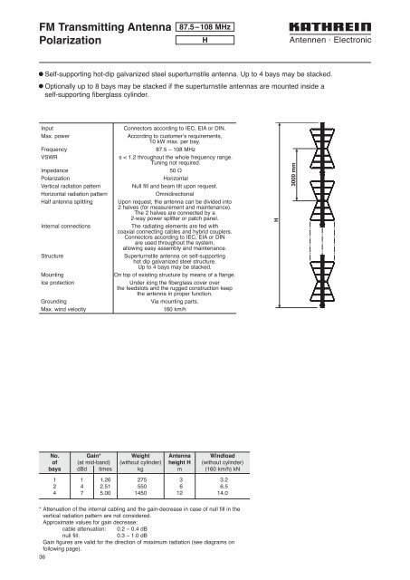
l Self-supporting hot-dip galvanized steel superturnstile antenna. Up to 4 bays may be stacked.<br />
l Optionally up to 8 bays may be stacked if the superturnstile antennas are mounted inside a<br />
self-supporting fiberglass cylinder.<br />
Input<br />
Max. power<br />
Frequency<br />
VSWR<br />
Impedance<br />
Polarization<br />
Vertical radiation pattern<br />
Horizontal radiation pattern<br />
Half antenna splitting<br />
Internal connections<br />
Structure<br />
Mounting<br />
Ice protection<br />
Grounding<br />
Max. wind velocity<br />
Connectors according to IEC, EIA or DIN.<br />
According to customer’s requirements,<br />
10 kW max. per bay.<br />
87.5 – 108 MHz<br />
s < 1.2 throughout the whole frequency range.<br />
Tuning not required.<br />
50 Ω<br />
Horizontal<br />
Null fill and beam tilt upon request.<br />
Omnidirectional<br />
Upon request, the antenna can be divided into<br />
2 halves (for measurement and maintenance).<br />
The 2 halves are connected by a<br />
2-way power splitter or patch panel.<br />
The radiating elements are fed with<br />
coaxial connecting cables and hybrid couplers.<br />
Connectors according to IEC, EIA or DIN<br />
are used throughout the system,<br />
allowing easy assembly and maintenance.<br />
Superturnstile antenna on self-supporting<br />
hot dip galvanized steel structure.<br />
Up to 4 bays may be stacked.<br />
On top of existing structure by means of a flange.<br />
Under icing the fiberglass cover over<br />
the feedslots and the rugged construction keep<br />
the antenna in proper function.<br />
Via mounting parts.<br />
160 km/h<br />
H<br />
3000 mm<br />
No. Gain* Weight Antenna Windload<br />
of (at mid-band) (without cylinder) height H (without cylinder)<br />
bays dBd times kg m (160 km/h) kN<br />
1 1 1.26 275 3 3.2<br />
2 4 2.51 550 6 6.5<br />
4 7 5.00 1450 12 14.0<br />
* Attenuation of the internal cabling and the gain-decrease in case of null fill in the<br />
vertical radiation pattern are not considered.<br />
Approximate values for gain decrease:<br />
cable attenuation: 0.2 – 0.4 dB<br />
null fill:<br />
0.3 – 1.0 dB<br />
Gain figures are valid for the direction of maximum radiation (see diagrams on<br />
following page).<br />
36