Druckschrift 99811574, Professional Broadcast Antennas - Kathrein
Druckschrift 99811574, Professional Broadcast Antennas - Kathrein
Druckschrift 99811574, Professional Broadcast Antennas - Kathrein

Create successful ePaper yourself
Turn your PDF publications into a flip-book with our unique Google optimized e-Paper software.
UHF Transmitting Antenna<br />
Polarization<br />
470–862 MHz<br />
H<br />
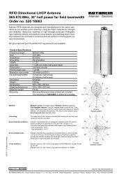
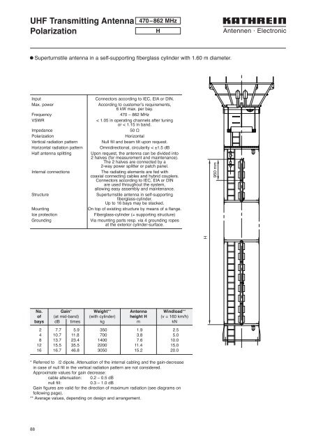
l Superturnstile antenna in a self-supporting fiberglass cylinder with 1.60 m diameter.<br />
Input<br />
Max. power<br />
Frequency<br />
VSWR<br />
Impedance<br />
Polarization<br />
Vertical radiation pattern<br />
Horizontal radiation pattern<br />
Half antenna splitting<br />
Internal connections<br />
Structure<br />
Mounting<br />
Ice protection<br />
Grounding<br />
Connectors according to IEC, EIA or DIN.<br />
According to customer’s requirements,<br />
6 kW max. per bay.<br />
470 – 862 MHz<br />
< 1.05 in operating channels after tuning<br />
or < 1.15 in band.<br />
50 Ω<br />
Horizontal<br />
Null fill and beam tilt upon request.<br />
Omnidirectional, circularity < ±1.5 dB<br />
Upon request, the antenna can be divided into<br />
2 halves (for measurement and maintenance).<br />
The 2 halves are connected by a<br />
2-way power splitter or patch panel.<br />
The radiating elements are fed with<br />
coaxial connecting cables and hybrid couplers.<br />
Connectors according to IEC, EIA or DIN<br />
are used throughout the system,<br />
allowing easy assembly and maintenance.<br />
Superturnstile antenna in self-supporting<br />
fiberglass-cylinder.<br />
Up to 16 bays may be stacked.<br />
On top of existing structure by means of a flange.<br />
Fiberglass-cylinder (= supporting structure)<br />
Via mounting parts resp. via 4 grounding ropes<br />
at the exterior cylinder-surface.<br />
950 mm<br />
H<br />
No. Gain* Weight** Antenna Windload**<br />
of (at mid-band) (with cylinder) height H (v = 160 km/h)<br />
bays dB times kg m kN<br />
2 7.7 5.9 350 1.9 2.5<br />
4 10.7 11.8 700 3.8 5.0<br />
8 13.7 23.4 1400 7.6 10.0<br />
12 15.5 35.5 2200 11.4 15.0<br />
16 16.7 46.8 3050 15.2 20.0<br />
* Referred to /2 dipole. Attenuation of the internal cabling and the gain-decrease<br />
in case of null fill in the vertical radiation pattern are not considered.<br />
Approximate values for gain decrease:<br />
cable attenuation: 0.2 – 0.5 dB<br />
null fill:<br />
0.3 – 1.0 dB<br />
Gain figures are valid for the direction of maximum radiation (see diagrams on<br />
following page).<br />
** Average values, depending on design and arrangement.<br />
88