Druckschrift 99811574, Professional Broadcast Antennas - Kathrein
Druckschrift 99811574, Professional Broadcast Antennas - Kathrein
Druckschrift 99811574, Professional Broadcast Antennas - Kathrein

Create successful ePaper yourself
Turn your PDF publications into a flip-book with our unique Google optimized e-Paper software.
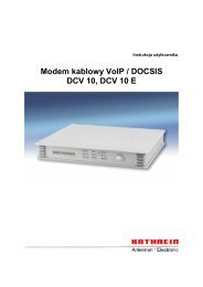
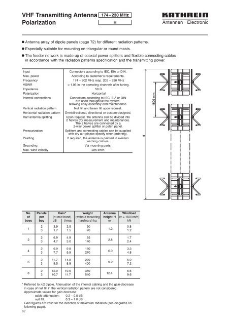
VHF Transmitting Antenna<br />
Polarization<br />
174–230 MHz<br />
H<br />
l Antenna array of dipole panels (page 72) for different radiation patterns.<br />
l Especially suitable for mounting on triangular or round masts.<br />
l The feeder network is made up of coaxial power splitters and flexible connecting cables<br />
in accordance with the radiation patterns specification and the transmitting power.<br />
Input<br />
Max. power<br />
Frequency<br />
VSWR<br />
Impedance<br />
Polarization<br />
Internal connections<br />
Vertical radiation pattern<br />
Horizontal radiation pattern<br />
Half antenna splitting<br />
Pressurization<br />
Painting<br />
Grounding<br />
Max. wind velocity<br />
Connectors according to IEC, EIA or DIN.<br />
According to customer’s requirements.<br />
174 – 202 MHz resp. 202 – 230 MHz<br />
< 1.05 in the operating channels after tuning.<br />
50 Ω<br />
Horizontal<br />
Connectors according to IEC, EIA or DIN<br />
are used throughout the system,<br />
allowing easy assembly and maintenance.<br />
Null fill and beam tilt upon request.<br />
Omnidirectional, directional or custom-designed.<br />
Upon request, the antenna can be divided into<br />
2 halves (for measurement and maintenance).<br />
The 2 halves are connected by a<br />
2-way power splitter or patch panel.<br />
Splitters and connecting cables can be supplied<br />
with dry air (please specify when ordering).<br />
If required, the antenna is painted in aviation<br />
warning colours.<br />
Via mounting parts.<br />
225 km/h<br />
H<br />
1600 mm<br />
No. Panels Gain* Weight Antenna Windload<br />
of per (at mid-band) (without mounting height H (v = 160 km/h)<br />
bays bay dB times hardware) kg m kN<br />
1<br />
2<br />
4<br />
6<br />
8<br />
2 3.9 2.5 50 0.8<br />
3 1.7 1.5 70<br />
1.2<br />
1.2<br />
2 6.9 4.9 95 1.7<br />
3 4.7 3.0 140<br />
2.8<br />
2.4<br />
2 9.9 9.8 180 3.3<br />
3 7.7 5.9 270<br />
6.0<br />
4.8<br />
2 11.7 14.8 270 5.0<br />
3 9.5 8.9 400<br />
9.2<br />
7.2<br />
2 12.9 19.5 360 6.6<br />
3 10.7 11.7 540<br />
12.4<br />
9.6<br />
* Referred to λ/2 dipole. Attenuation of the internal cabling and the gain-decrease<br />
in case of null fill in the vertical radiation pattern are not considered.<br />
Approximate values for gain decrease:<br />
cable attenuation: 0.2 – 0.5 dB<br />
null fill:<br />
0.3 – 1.0 dB<br />
Gain figures are valid for the direction of maximum radiation (see diagrams on<br />
following page).<br />
62