Digital Air/Fuel Ratio Gauge User Manual - Innovate Motorsports
Digital Air/Fuel Ratio Gauge User Manual - Innovate Motorsports
Digital Air/Fuel Ratio Gauge User Manual - Innovate Motorsports

You also want an ePaper? Increase the reach of your titles
YUMPU automatically turns print PDFs into web optimized ePapers that Google loves.
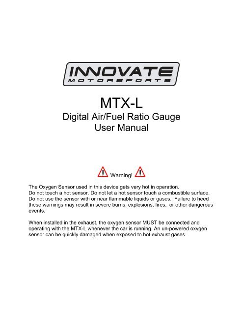
MTX-L<br />
<strong>Digital</strong> <strong>Air</strong>/<strong>Fuel</strong> <strong>Ratio</strong> <strong>Gauge</strong><br />
<strong>User</strong> <strong>Manual</strong><br />
Warning!<br />
The Oxygen Sensor used in this device gets very hot in operation.<br />
Do not touch a hot sensor. Do not let a hot sensor touch a combustible surface.<br />
Do not use the sensor with or near flammable liquids or gases. Failure to heed<br />
these warnings may result in severe burns, explosions, fires, or other dangerous<br />
events.<br />
When installed in the exhaust, the oxygen sensor MUST be connected and<br />
operating with the MTX-L whenever the car is running. An un-powered oxygen<br />
sensor can be quickly damaged when exposed to hot exhaust gases.
TABLE OF CONTENTS<br />
1 MTX-L ....................................................................................................................................................3<br />
2 Installation..............................................................................................................................................4<br />
2.1 Wiring ...............................................................................................................................................4<br />
2.2 Mounting and Routing......................................................................................................................4<br />
2.3 Sensor Placement............................................................................................................................5<br />
2.4 Sensor Calibration............................................................................................................................6<br />
2.5 Calibration Schedule........................................................................................................................7<br />
3 Software (LogWorks 3 and LM Programmer)........................................................................................8<br />
3.1 Installing software ............................................................................................................................8<br />
3.2 Connecting to LM Programmer........................................................................................................8<br />
3.2.1 Analog Outputs........................................................................................................................9<br />
3.2.2 Advanced output programming .............................................................................................10<br />
3.2.3 Customizing your fuel type ....................................................................................................11<br />
3.2.4 Customizing your display range ............................................................................................11<br />
3.2.5 Updating the firmware ...........................................................................................................12<br />
3.3 Logging data from your MTX-L with LogWorks .............................................................................12<br />
4 Wiring Analog Outputs.........................................................................................................................12<br />
5 Tips, Tricks, & Troubleshooting ...........................................................................................................13<br />
5.1 <strong>Air</strong>/<strong>Fuel</strong> and Lambda......................................................................................................................13<br />
5.2 General measurement requirements .............................................................................................14<br />
5.3 Vehicles with ‘smog-pumps’...........................................................................................................14<br />
5.4 Single Cylinder Engines.................................................................................................................14<br />
5.5 Diesel Engines ...............................................................................................................................14<br />
5.6 Connecting the MTX-L to simulate a narrow band oxygen sensor................................................15<br />
Appendix A: Specifications..........................................................................................................................17<br />
Appendix B: Limited Warranty ....................................................................................................................18<br />
Appendix C: Connectors .............................................................................................................................19<br />
Appendix E: Error Codes and Troubleshooting Tips ..................................................................................20<br />
2<br />
Document #<br />
MTX-L_<strong>Manual</strong>.doc
1 MTX-L<br />
The MTX-L is an integrated gauge and controller for wideband AFR (lambda)<br />
measurements. Although it can be operated stand alone, it has digital I/O for integration<br />
with other MTS compatible products and two configurable analog outputs for integration<br />
with ECU’s and 3 rd party data loggers. The following views will help you get familiar with<br />
the unit.<br />
Needle Bar<br />
Status Light<br />
Numeric Display<br />
Mounting Bracket<br />
Serial Connectors<br />
Wiring Loom<br />
Sensor Connector<br />
3<br />
Document #<br />
MTX-L_<strong>Manual</strong>.doc
2 Installation<br />
2.1 Wiring<br />
The MTX-L has 5 stripped wire ends.<br />
1. Connect the RED wire to a switched 12V source. A switched 12V source goes on as<br />
soon as the ignition on the car is on. Make sure the connection is fused with a<br />
minimum fuse size of 3A.<br />
2. Connect the BLACK wire to a ground source. Avoid noisy ground sources, such as<br />
grounds used for radio and or ignition sources.<br />
3. Connect the WHITE wire to a headlight power wire (a wire that supplies current to<br />
the headlights). This enables the display to dim for better nighttime viewing. DO<br />
NOT CONNECT THIS WIRE TO THE HEADLIGHT DIMMING WIRE. Connection to<br />
this rheostat type of switch will cause the gauge to malfunction. If you chose not to<br />
utilize the dimming feature, connect the WHITE wire to ground.<br />
4. Optionally, the YELLOW (Analog out 1) and/or BROWN (Analog out 2) can be<br />
connected to the analog inputs of other devices such as data loggers or ECUs. If<br />
either one or both of these wires are not being used isolate and tape the wire(s) out<br />
of the way. The default analog outputs are as follows: Analog output one (yellow) is<br />
0V = 7.35 AFR and 5V = 22.39 AFR. Analog output two (brown) is 1.1V = 14 AFR<br />
and .1V = 15 AFR. This is a simulated narrowband signal.<br />
2.2 Mounting and Routing<br />
The MTX-L can be mounted in any standard 2 1/16” (52mm) gauge pod. Mounting the<br />
gauge should be done in such a way so that the cables are not being forcefully pulled<br />
from the gauge itself.<br />
Route the sensor cable avoiding contact with the exhaust pipe and other hot sources<br />
that could melt the cable. Also avoid routing the sensor cable near ignition components<br />
or other sources of RF (radio frequency) and EMI (Electromagnetic interference) noise.<br />
4<br />
Document #<br />
MTX-L_<strong>Manual</strong>.doc
2.3 Sensor Placement<br />
Your MTX-L gauge kit includes a 1” bung. This bung is supplied to best prolong the life<br />
of your sensor since it will allow the sensor to sit flush with the exhaust pipe. Using a<br />
bung is the preferred method for mounting the O 2 sensor for both catalytic and noncatalytic<br />
cars.<br />
On CATALYTIC CONVERTER equipped vehicles:<br />
Install the oxygen sensor’s bung upstream from the catalytic converter (a bung is<br />
included in the MTX-L kit). The bung must be installed in the exhaust pipe at the side<br />
or on top, NOT on the bottom of the exhaust pipe. Any decent muffler or exhaust<br />
shop can do this for you. The wide-band oxygen sensor is then installed into the<br />
bung to take a reading. The ideal position is between 10:00 and 2:00 position.<br />
On NON-CATALYTIC converter vehicles:<br />
You have the option with non-catalytic cars to also use an exhaust clamp as<br />
described below. Use of a bung is the preferred method for mounting the 0 2 sensor<br />
for both catalytic and non-catalytic cars.<br />
On TURBO CHARGED vehicles:<br />
Install the bung downstream from the turbo but before the catalytic converter. The<br />
high exhaust pressure before the turbo interferes with the lambda measurement and<br />
the high exhaust temperatures encountered there can damage the sensor.<br />
Alternatively you can also use the optional exhaust clamp (part number 3728) to sample<br />
exhaust gases at the end of the tail pipe.<br />
Do NOT install the Bung below the 3 o'clock or 9 o'clock position. Condensation<br />
can form in the exhaust pipe and permanently damage the sensor. 6 o’clock is the<br />
absolute worst position to mount the sensor.<br />
5<br />
Document #<br />
MTX-L_<strong>Manual</strong>.doc
Wide band oxygen sensors, like the one shipped with the MTX-L, are designed<br />
to work with unleaded gasoline. Use with leaded gasoline will significantly reduce the<br />
lifespan of the sensor. The reduction is directly proportional to the metal content of the<br />
fuel and the tune of the engine.<br />
WHEN INSTALLED IN THE EXHAUST, THE OXYGEN SENSOR MUST BE<br />
CONNECTED AND OPERATING WITH THE MTX-L WHENEVER THE CAR IS<br />
RUNNING. AN UN-POWERED OXYGEN SENSOR WILL BE DAMAGED WHEN<br />
EXPOSED TO EXHAUST GAS IF NOT PROPERLY POWERED.<br />
The maximum temperature of the sensor at the bung (the sensor hexagon)<br />
should not exceed 500 o C or 900 o F. If these temperatures are exceeded in your<br />
application you should install the <strong>Innovate</strong> <strong>Motorsports</strong> Heat-Sink Bung extender (P/N<br />
3729 HBX-1).<br />
It is NOT a good idea to do a sensor prewarm-up prior to starting the engine.<br />
Depending on the climate and the sensor position in the exhaust, condensation can<br />
form in the exhaust pipes. This condensation could then be blown by the exhaust<br />
stream against the hot sensor when the car is started. The resulting heat shock can<br />
permanently damage the sensor.<br />
2.4 Sensor Calibration<br />
Once the unit has been wired and a suitable location has been found for both the gauge<br />
and the sensor it is time to do the sensor calibration. <strong>Innovate</strong> <strong>Motorsports</strong>’ ‘Direct<br />
<strong>Digital</strong>’ wideband measurement principal allows you to calibrate the sensor to<br />
compensate for sensor wear. This procedure takes just a few moments and it will insure<br />
the most accurate readings throughout the oxygen sensor’s life. This procedure is<br />
required anytime a NEW oxygen sensor is installed.<br />
The calibration procedure requires that the oxygen sensor be in free air, not in the<br />
exhaust. Important: Just because a vehicle is not running does not mean that the<br />
exhaust system is free of gases.<br />
1. With the sensor disconnected, apply power to the MTX-L.<br />
When power is applied, all three digits will light up and the needle bar will sweep<br />
once through all LEDs. Then the status light will turn red and the numeric display will<br />
read “E2”. This is an error code, indicating that no sensor is detected. Leave unit<br />
powered on for minimum 30 seconds.<br />
6<br />
Document #<br />
MTX-L_<strong>Manual</strong>.doc
2. Power down the MTX-L and attach the oxygen sensor using the cable provided.<br />
Again, make sure that the sensor is in free air (not in the exhaust).<br />
3. Power up the MTX-L.<br />
Again, the display should ‘sweep’, but instead of an error, the display will display<br />
“Htr”. This indicates that the sensor is being heated up to operating temperature.<br />
After 30-60 seconds, the display will switch from “Htr” to “CAL”, indicating that the<br />
sensor is being calibrated. A few seconds later, your MTX-L will begin displaying<br />
AFR. Since the sensor is in free air, the gauge will default to the upper limit of 22.4.<br />
The calibration procedure has completed and the system is now ready for use.<br />
Important: You can disconnect and reconnect the sensor and sensor cable for<br />
installation without losing your calibration. However, if you power up the MTX-L<br />
without a sensor connected, your calibration will be reset (see step #1 above).<br />
2.5 Calibration Schedule<br />
Normally aspirated (daily driver)<br />
- Calibrate before installation of new sensor<br />
- Calibrate new sensor again after 3 month of use<br />
- Thereafter calibrate once a year or every 20,000 miles, whichever comes first<br />
Turbo Application, daily driver (tuned rich)<br />
- Calibrate before installation of new sensor<br />
- Calibrate new sensor again after 3 month of use<br />
- Thereafter calibrate twice a year or every 10,000 miles, whichever comes first<br />
Race Application<br />
- Calibrate before first installation of new sensor<br />
- Calibrate once per race weekend<br />
Dyno use:<br />
- Calibrate a new sensor<br />
- Calibrate every 2-3 days, depending on usage<br />
7<br />
Document #<br />
MTX-L_<strong>Manual</strong>.doc
3 Software (LogWorks 3 and LM Programmer)<br />
3.1 Installing software<br />
1. Install the CD that came with your MTX-L on your Windows based personal<br />
computer.<br />
2. The installer will automatically start, follow the prompts to install the software.<br />
3. Once the software has been installed the LogWorks software, LM Programmer and<br />
MTX-L manual can then be located by navigating through Start->Programs-<br />
>LogWorks3.<br />
3.2 Connecting to LM Programmer<br />
LM Programmer is used to update firmware, change fuel types, set display ranges, and<br />
program the two analog outputs.<br />
1. Connect the OUT port of the MTX-L to the provided serial programming cable.<br />
Connect the other end of the serial programming cable to your computer. If your<br />
computer does not have a serial port, you can purchase a USB to Serial adapter<br />
from <strong>Innovate</strong> <strong>Motorsports</strong> (P/N 3733) or use any USB to serial adaptor that<br />
includes drivers. Make sure that nothing is connected to the IN port of the MTX-L.<br />
2. Power up the MTX-L.<br />
3. Launch LM Programmer. The LM Programmer application can be launched from<br />
Start->Programs->LogWorks3->LM Programmer from the Windows task bar.<br />
8<br />
Document #<br />
MTX-L_<strong>Manual</strong>.doc
3.2.1 Analog Outputs<br />
1. Connect the MTX-L to the computer and launch LM Programmer.<br />
2. Select one of the Analog output tabs. The Analog output page looks like this:<br />
This shows the analog output voltages versus Lambda for one of the two analog outputs.<br />
The graph display is automatically scaled to the selected voltages. For each output you<br />
can specify a minimum and maximum lambda value and the associated voltages. Below<br />
the minimum and above the maximum lambda values the output voltages stay constant<br />
at the associated programmed voltage.<br />
By selecting the ‘use <strong>Air</strong>-<strong>Fuel</strong>-<strong>Ratio</strong>’ button you can program the curve by AFR instead<br />
of Lambda. This does not change the programming, only the representation of the data.<br />
When programming by AFR the LM Programmer converts the number to Lambda<br />
before programming the MTX-L. So there might be some small ‘rounding errors’ when<br />
you open LM Programmer and review your settings in the future.<br />
Click the ‘Program’ button to download the new data into the MTX-L. Once the unit is<br />
programmed the ‘Program’ button will grey out.<br />
9<br />
Document #<br />
MTX-L_<strong>Manual</strong>.doc
Factory Programmed Defaults:<br />
Analog Output 1 is programmed to output between 0 V for an AFR of 7.35 (gasoline)<br />
and 5.0V for an AFR of 22.39. Analog Output 2 simulates a typical narrow band oxygen<br />
sensor. The configuration is 1.1 V for an AFR of 14 and .1 V for an AFR of 15.<br />
Other curves, of course, are easily programmable.<br />
3.2.2 Advanced output programming<br />
The ‘Advanced’ button allows programming to set the analog out update speed and the<br />
voltage output during sensor Warm-up and Error Condition. The factory defaults of the<br />
analog outputs is to update the outputs 1/12 of a second. The factory default voltage<br />
output is set for 0 volts for both the Warm-up and Error Condition.<br />
When setting the MTX-L to the slower response speed settings the measured mixture<br />
data will be averaged over the response time setting before being output.<br />
10<br />
Document #<br />
MTX-L_<strong>Manual</strong>.doc
3.2.3 Customizing your fuel type<br />
The MTX-L gauge comes preprogrammed<br />
to display AFR in the<br />
gasoline scale. By connecting the<br />
gauge to LM Programmer, fuel type<br />
settings for different fuels can be<br />
setup. This setting can be found on<br />
the lower right hand corner of the<br />
Info tab in LM Programmer.<br />
3.2.4 Customizing your display range<br />
The MTX-L gauge can be setup to<br />
display different ranges from both the<br />
Needle Bar and the Numeric Display.<br />
There is also an option to display<br />
lambda or AFR. Lastly, the gauge can<br />
be setup to display percentage of<br />
Oxygen once the readings go beyond<br />
7 lambda.<br />
11<br />
Document #<br />
MTX-L_<strong>Manual</strong>.doc
3.2.5 Updating the firmware<br />
1. Connect the MTX-L to the computer and launch LM Programmer.<br />
2. Once connected, LM Programmer will display the current version of the firmware<br />
that is installed in the MTX-L. Do not update the firmware if the versions are the<br />
same. A firmware update should only be necessary if there has been a new<br />
release.<br />
3. On the very first tab of LM Programmer you will see a button labeled “Update<br />
Firmware,” click this button.<br />
4. Select the firmware file with the dld extension. The latest firmware file will be<br />
available for download from the Support section of the <strong>Innovate</strong> <strong>Motorsports</strong> web<br />
site.<br />
5. The software will now prompt you to confirm that you wish to overwrite the<br />
firmware currently on your MTX-L.<br />
6. Click OK, DO NOT power off or disconnect the MTX-L from the computer until<br />
the firmware progress screen completely disappears. Once finished you may<br />
disconnect the unit from the computer and exit out of the software.<br />
3.3 Logging data from your MTX-L with LogWorks<br />
1. Connect the OUT port of the MTX-L to the provided serial programming cable.<br />
Connect the other end of the serial programming cable to your computer. If your<br />
computer does not have a serial port, you can purchase a USB to Serial adapter<br />
from <strong>Innovate</strong> <strong>Motorsports</strong> (P/N 3733) or use any USB to serial adaptor that<br />
includes drivers. Make sure that nothing is connected to the IN port of the MTX-L.<br />
Power up the MTX-L<br />
2. Launch LM Programmer. The LM Programmer application can be launched from<br />
Start->Programs->LogWorks3->Logworks3 from the Windows task bar.<br />
3. Once LogWorks launches go to File->Connect. You will be prompted to connect<br />
to serial COM port. Click Connect.<br />
4. To start recording go to File->New Realtime Log or, in the Toolbar, click on the<br />
Tool.<br />
4 Wiring Analog Outputs<br />
The analog outputs on the MTX-L are ‘single ended’. That is, each output uses just one<br />
wire. It is assumed that the MTX-L and the device it is being connected to are already<br />
sharing the same ‘ground’. In a vehicle, this is generally true, but there can be small<br />
offsets in voltage when devices are grounded to, say, the chassis at different points.<br />
You can minimize these offsets by sharing a good, common ground point, or you can<br />
adjust for them by configuring the analog output voltages on the MTX-L.<br />
12<br />
Document #<br />
MTX-L_<strong>Manual</strong>.doc
5 Tips, Tricks, & Troubleshooting<br />
5.1 <strong>Air</strong>/<strong>Fuel</strong> and Lambda<br />
The Stoichiometric AFR value is the AFR multiplier. So for (standard, unblended)<br />
gasoline its 14.7. If you set it to 14.7 the MTX-L display will show 14.7 AFR for Lambda<br />
1.0. If you set it to 6.4 (methanol) the MTX-L will show 6.4 AFR for Lambda 1.0.<br />
You can look at Lambda as the percent of richness. If running Lambda 0.85 (12.5 AFR<br />
for gasoline) you are running 15% rich. For methanol 15% rich means 5.44 AFR. That's<br />
where the value of Lambda comes in. If you run blended fuels where you don't know the<br />
stoich value, you look at Lambda and adjust to 10-20% rich, depending where your max<br />
power is. The % value of richness required by an engine (for max power) does change<br />
relatively little (fairly independent of fuel). But if for example you adjust an engine<br />
running methanol to 12.5 AFR, you would be running so lean that it would probably not<br />
even run.<br />
The MTX-L can be used to read <strong>Air</strong>/<strong>Fuel</strong> <strong>Ratio</strong> (AFR) or Lambda for an engine. For<br />
gasoline-driven engines, the theoretically optimal air fuel ratio for efficiency is 14.7<br />
pounds of air for every pound of fuel. At this ratio, theoretically, all available oxygen in<br />
the air combines with all available fuel. This ratio is called the stoichiometric ratio.<br />
Stoichiometric for different fuels are as follows:<br />
Gasoline 14.7<br />
LPG (Propane) 15.5<br />
Methanol 6.4<br />
Ethanol 9.0<br />
CNG 17.2<br />
Diesel 14.6<br />
The measurement Lambda is the actual air fuel ratio over the stoichiometric ratio. A<br />
Lambda measurement of “1” equates to the air fuel ratio of 14.7 (for gasoline engines).<br />
When Lambda is less than 1 the engine runs “rich”, i.e., unburned fuel exists in the<br />
exhaust stream. If lambda is greater than 1 the engine runs lean, i.e., free oxygen (0 2 ) is<br />
present in the exhaust. Depending on the engine, maximum power is typically delivered<br />
when the engine runs slightly rich (for example at lambda values of 0.8 to 0.9 for most<br />
engines). This instrument provides a means to measure the actual air fuel ratio or<br />
lambda in the engine in operation directly from the exhaust. For this a special wide-band<br />
oxygen sensor is used to measure the lambda value derived from the oxygen content<br />
(or lack thereof) of the exhaust gases.<br />
13<br />
Document #<br />
MTX-L_<strong>Manual</strong>.doc
5.2 General measurement requirements<br />
The MTX-L measures the air-fuel-ratio by measuring the amount of oxygen in the<br />
exhaust (for lean conditions) or the amount of unburned or partially burned fuel (for rich<br />
conditions). You should correct for the following in order to get optimum results from the<br />
MTX-L:<br />
1) An exhaust leak will allow oxygen to enter the exhaust stream and therefore<br />
will measure leaner than the engine is actually running. For correct<br />
measurement, air-leaks in the exhaust MUST be prevented under all<br />
circumstances.<br />
2) Missing ignitions (where the air-fuel mixture does not ignite) also pump<br />
unburned oxygen into the exhaust and cause the MTX-L to measure lean.<br />
3) The only circumstance where the MTX-L will measure richer than the engine<br />
is running is if the pressure in the exhaust tract is excessive (and the engine<br />
is running on the rich side to begin with).<br />
5.3 Vehicles with ‘smog-pumps’<br />
Older fuel injected vehicles with a ‘smog-pump’ actually inject air into the exhaust<br />
stream to aid their catalytic converter in the burn-up of unburned or partially burned<br />
fuels. This additional air will make the exhaust look leaner than the engine is running.<br />
For an accurate measure, install the MTX-L sensor up-stream of the outputs of the<br />
smog-pump. If this is not possible, temporarily disable the smog-pump by removing its<br />
drive belt.<br />
5.4 Single Cylinder Engines<br />
These kinds of engines are difficult to measure at the tail-pipe using an Exhaust Clamp.<br />
The oscillations of the exhaust gas are so large that a lot of outside air enters the<br />
exhaust and prevents correct measurement. Sometimes it helps to temporarily wrap a<br />
piece of heat resistant cloth around the exhaust clamp to prevent outside air from<br />
entering the exhaust.<br />
5.5 Diesel Engines<br />
Diesel Engines and gas turbines run at wide open throttle at all times. They do not have<br />
a throttle but regulate power by the amount of injected fuel. The MTX-L can still be used,<br />
but measurements at idle will read as lean.<br />
14<br />
Document #<br />
MTX-L_<strong>Manual</strong>.doc
5.6 Connecting the MTX-L to simulate a narrow band oxygen sensor<br />
It is possible to install the wide-band sensor in place of the OEM oxygen sensor. In this<br />
case the meter's analog output signal will replace the OEM oxygen sensor's signal to<br />
the fuel injection computer. Note: Please review your analog output settings; the<br />
configuration for a narrowband is 1.1 V for an AFR of 14 and .1 V for an AFR of 15.<br />
EFI equipped cars typically incorporate a narrow band oxygen sensor. These sensors<br />
are typically 1, 2, 3 or 4 wire sensors. Some vehicles are equipped with oxygen sensors<br />
that do not produce an output voltage but change their resistance depending on exhaust<br />
gas content. These sensors cannot be simulated. They are used in less than 1% of all<br />
vehicles. Refer to your vehicles specifications if you think that your vehicle may be in<br />
this category. The same is true for vehicles already factory equipped with a wide-band<br />
oxygen sensor. These cannot be simulated either.<br />
Some EFI-computers will create a fault when the heater power wires of the oxygen<br />
sensor are disconnected. In this case mount the old oxygen sensor in a safe place (but<br />
not necessarily in the exhaust) and connect the heater wires to it to keep the EFIcomputer<br />
happy.<br />
Be careful where you mount the stock sensor, as heated sensors will get hot.<br />
To connect the MTX-L to the EFI-computer, first determine what kind of narrow band<br />
sensor is used, then follow the instructions below (you will need a digital multimeter to<br />
determine correct OEM sensor wires):<br />
a. Vehicle has a 1-wire sensor:<br />
Wire analog output 1 directly to the wire.<br />
b. Vehicle has a 2-wire sensor:<br />
While the engine is off determine which of the 2 wires has a low resistance between the<br />
wire and the sensor body. This is the heater power for the sensor. Wire analog output 1<br />
directly to the other wire. Leave the heater power wire unconnected but make sure it<br />
cannot ground itself.<br />
c. Vehicle has a 3-wire sensor:<br />
Typically the 3 wires are: heater power, Ground, and sensor element connection.<br />
Generally they have 1 black wire and 2 white wires. Connect the black wire from the EFI<br />
computer to analog output 1 of the meter. Leave the other wires unconnected but make<br />
sure they cannot contact any metal parts or see above. If the wiring colors are different,<br />
then heater power can simply be determined by measuring the voltage on the wires<br />
when the engine is running. The wire showing 12V or more is the heater power. The<br />
sensor element connection voltage fluctuates around 0.45V when the car is warmed up.<br />
15<br />
Document #<br />
MTX-L_<strong>Manual</strong>.doc
Wire analog output 1 directly to this wire. The Ground connection has low resistance to<br />
chassis ground (less than 1 Ohm). Measure while the engine is off.<br />
d. Vehicle has a 4-wire sensor<br />
Typically the 4 wires are: heater power, heater ground, sensor ground, and sensor<br />
element connection. Proceed as for the 3-wire sensor.<br />
16<br />
Document #<br />
MTX-L_<strong>Manual</strong>.doc
Appendix A: Specifications<br />
Power<br />
Power requirements<br />
Serial Communication<br />
Serial Port Speed<br />
Packet/Logging Speed<br />
Sample Resolution<br />
Mechanical<br />
Hole Size<br />
Software<br />
Supported OSs<br />
Temperature<br />
Max Operating<br />
Temperature<br />
8-18 Volt / 2 A (max, 1 A nominal)<br />
19.2 kbit/sec<br />
81.92 msec/sample packet<br />
10 bits (0..5V at 0.1% resolution)<br />
2 1/16” (52mm)<br />
Windows 98, ME, 2000, XP, and Vista<br />
-20 to +85 deg Celsius<br />
17<br />
Document #<br />
MTX-L_<strong>Manual</strong>.doc
Appendix B: Limited Warranty<br />
LIMITED WARRANTY<br />
<strong>Innovate</strong> stands behind the quality of its products. <strong>Innovate</strong> makes the following warranty to purchasers of<br />
its products: All new <strong>Innovate</strong> products carry a one year warranty from the date of purchase. If proof of<br />
purchase cannot be provided, warranty will be determined by date of manufacture.<br />
When Warranty Void<br />
This warranty shall terminate and <strong>Innovate</strong> shall have no obligation pursuant to it if (i) your <strong>Innovate</strong><br />
product has been modified or repaired in a manner not previously authorized by <strong>Innovate</strong> in writing, (ii)<br />
the identification markings on your <strong>Innovate</strong> product have been removed, defaced, or altered; (iii) your<br />
<strong>Innovate</strong> product was subjected to accident, abuse, shipping damage, or improper use; (iv) your <strong>Innovate</strong><br />
product was not used or configured as specified in the product manual; or (v) your <strong>Innovate</strong> product was<br />
subjected to operating conditions more severe than those specified in the product manual.<br />
Exclusions From This Warranty<br />
Oxygen Sensors are excluded from this warranty.<br />
Repairs Under This Warranty<br />
In the unlikely event that your <strong>Innovate</strong> hardware product should prove defective during the warranty<br />
period, contact <strong>Innovate</strong> Customer Support at www.innovatemotorsports.com for a return material<br />
authorization (RMA) or at (800) 348-3037. Products returned for service must be securely packed to<br />
prevent damage and shipped charges pre paid, along with proof of purchase and the return material<br />
authorization number, to the <strong>Innovate</strong> repair location as instructed by Customer Service. <strong>Innovate</strong> within a<br />
reasonable amount of time from its receipt of your product so shipped, will ship to you, at its option, the<br />
repaired product or a new or reconditioned product of comparable or greater specified functionality. All<br />
repaired or replacement products shall be warranted for the remainder of the original product warranty.<br />
Disclaimer<br />
INNOVATE MAKES NO OTHER EXPRESS OR IMPLIED WARRANTY WITH RESPECT TO YOUR<br />
INNOVATE PRODUCT OTHER THAN THE LIMITED WARRANTY SET FORTH ABOVE. No <strong>Innovate</strong><br />
dealer, agent, or employee is authorized to make any modification, extension, or addition to this warranty,<br />
unless enforceable or unlawful under applicable law, INNOVATE DISCLAIMS ALL IMPLIED<br />
WARRANTIES, INCLUDING THE IMPLIED WARRANTIES OF MERCHANTABILITY,<br />
NONINFRINGEMENT, AND FITNESS FOR A PARTICULAR PURPOSE, AND THE LIABILITY OF<br />
INNOVATE, IF ANY, FOR DAMAGES RELATING TO ANY ALLEGEDLY DEFECTIVE PRODUCT SHALL<br />
UNDER ANY TORT, CONTRACT, OR OTHER LEGAL THEORY BE LIMITED TO THE ACTUAL PRICE<br />
PAID FOR SUCH PRODUCT AND SHALL IN NO EVENT INCLUDE INCIDENTAL, CONSEQUENTIAL,<br />
SPECIAL, OR INDIRECT DAMAGES OF ANY KIND EVEN IF INNOVATE IS AWARE OF THE<br />
POSSIBILITY OF SUCH DAMAGES. Some states do not allow limitations on how long an implied<br />
warranty lasts or the exclusion or limitation of incidental or consequential damages, so the above<br />
limitations or exclusions may not apply to you.<br />
18<br />
Document #<br />
MTX-L_<strong>Manual</strong>.doc
Appendix C: Connectors<br />
1. Sensor<br />
Pin<br />
Use<br />
1 IPUMP+<br />
2 SENSE/PUMP-<br />
3 SHTR<br />
4 VBAT<br />
5 SENSE+<br />
6 SHIELD GND<br />
7 SHTR<br />
8 VBAT<br />
2. Power and Analog Cable<br />
3. Serial Out<br />
Pin Use<br />
1 RX<br />
2 TX<br />
3 GND<br />
4 GND<br />
4. Serial In<br />
Pin Use<br />
1 TX<br />
2 RX<br />
3 GND<br />
4 *MTS Sense<br />
19<br />
Document #<br />
MTX-L_<strong>Manual</strong>.doc
Appendix E: Error Codes and Troubleshooting Tips<br />
Error<br />
Code<br />
Error 1<br />
Error 2*<br />
Error 3<br />
Error 4<br />
Error Message Likely Root Cause Fix<br />
Heater circuit<br />
shorted<br />
Heater circuit<br />
open<br />
Pump cell circuit<br />
shorted<br />
Pump cell circuit<br />
open<br />
1. Short in cable<br />
2. Short in sensor<br />
1. Damaged sensor cable.<br />
2. Cable connector not fully seated<br />
3. Sensor Damaged<br />
1. Short in sensor cable<br />
2. Short in sensor<br />
3. Sensor overheating<br />
4. EGT >1700º F<br />
1. Damaged sensor cable.<br />
2. Cable connector not fully<br />
seated<br />
3. Sensor Damaged<br />
1. Repair/replace cable.<br />
2. Replace sensor.<br />
1. Inspect sensor cable for rips or tears.<br />
2. Verify Sensor is fully seated into<br />
connector, make sure it ‘clicks.’<br />
3. Replace Sensor<br />
1. Repair sensor cable.<br />
2. Replace sensor.<br />
3. Move your sensor bung as far<br />
downstream as possible OR add a<br />
heatsink to isolate the sensor from the<br />
pipe.<br />
1. Inspect Sensor cable for rips or tears.<br />
2. Verify Sensor is fully seated into<br />
connector, make sure it ‘clicks.’<br />
3. Replace Sensor<br />
Error 5<br />
Error 6<br />
Reference cell<br />
circuit shorted<br />
Reference cell<br />
circuit open<br />
1. Short in sensor cable<br />
2. Short in sensor<br />
1. Cable connector not fully<br />
seated<br />
2. Damaged sensor cable<br />
3. Damaged Sensor<br />
1. Inspect sensor cable for rips or tears.<br />
2. Replace sensor.<br />
1. Verify Sensor is fully seated into<br />
connector, make sure it ‘clicks.’<br />
2. Inspect sensor cable for rips or tears.<br />
3. Replace sensor<br />
Error 7<br />
Error 8<br />
Error 9<br />
General System<br />
error (typically a<br />
software error).<br />
Sensor Timing<br />
error (typically a<br />
damaged<br />
sensor).<br />
Software error<br />
1. Sensor overheating.<br />
(The Bosch LSU4.2 is rated to<br />
operate at a sensor housing<br />
temperature of < 900 degrees<br />
(measured at the bung) for<br />
maximum accuracy and control.<br />
When this operating temperature<br />
range is exceeded, the sensor can<br />
no longer be accurately<br />
controlled.)<br />
2. Sensor is damaged<br />
3. Overly Rich condition<br />
Supply voltage too low for sensor<br />
regulation<br />
Reboot MTX-L by cycling power.<br />
Reload firmware if necessary.<br />
1. a. Perform sensor heater<br />
recalibration; b. Move your sensor<br />
bung as far downstream as possible.<br />
Right before the cat, or 2-3 feet from the<br />
end of the tailpipe are good locations; c.<br />
Add a heatsink to isolate the sensor<br />
from the pipe. The HBX-1 is an<br />
available accessory.<br />
2. Replace sensor.<br />
3. Correct Tune and recalibrate the<br />
sensor.<br />
Supply Voltage<br />
Check your 12V connection for corrosion.<br />
too low<br />
* Whenever Error 2 is displayed, existing sensor calibration data is discarded.<br />
20<br />
Document #<br />
MTX-L_<strong>Manual</strong>.doc
Revision History<br />
1.0 11/18/10<br />
Initial Release<br />
21<br />
Document #<br />
MTX-L_<strong>Manual</strong>.doc