High Pressure Motor Valves - Home | Kimray Mobile - Kimray, Inc.
High Pressure Motor Valves - Home | Kimray Mobile - Kimray, Inc.
High Pressure Motor Valves - Home | Kimray Mobile - Kimray, Inc.

Create successful ePaper yourself
Turn your PDF publications into a flip-book with our unique Google optimized e-Paper software.
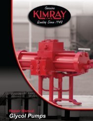
Repair Manual<br />
<strong>High</strong> <strong>Pressure</strong> <strong>Motor</strong> <strong>Valves</strong>
HIGH PRESSURE MOTOR VALVES REPAIR MANUAL<br />
INDEX<br />
Introduction .................................................................................................... 1<br />
Elastomers ..................................................................................................... 2<br />
Materials ........................................................................................................ 3<br />
<strong>Pressure</strong> Open to <strong>Pressure</strong> Close Conversion .............................................. 5<br />
HPMV Disassembly ....................................................................................... 9<br />
HMPV Inspection of Parts ............................................................................ 17<br />
HPMV Assembly .......................................................................................... 19<br />
HPMV Testing .............................................................................................. 25<br />
Piston Balanced Disassembly ..................................................................... 27<br />
Piston Balanced Inspection of Parts ............................................................ 35<br />
Piston Balanced Assembly .......................................................................... 37<br />
NOTE: We reserve the right to modify or change, without prior<br />
notice, any statement or information contained herein. If exact<br />
dimensions or specifications are required by the customer<br />
certified prints will be furnished for a minimum charge upon<br />
request to KIMRAY, <strong>Inc</strong>.<br />
® Copyright 2006, KIMRAY, <strong>Inc</strong>.<br />
www.kimray.com
HIGH PRESSURE MOTOR VALVE REPAIR MANUAL<br />
INTRODUCTION<br />
SCOPE<br />
This instruction manual contains repair information for the standard 1" and 2" <strong>Kimray</strong> <strong>High</strong> <strong>Pressure</strong> <strong>Motor</strong><br />
Valve and the 2” through 6” Piston Balanced <strong>High</strong> <strong>Pressure</strong> <strong>Motor</strong> Valve.<br />
DESCRIPTION<br />
The <strong>High</strong> <strong>Pressure</strong> <strong>Motor</strong> <strong>Valves</strong> are all actuated with a pneumatic actuator which features an open yoke and<br />
travel indicator. The actuators are reversible between pressure opening and pressure closing configurations.<br />
The standard <strong>High</strong> <strong>Pressure</strong> <strong>Motor</strong> Valve employs a ball and cone seat configuration. The Piston Balanced<br />
<strong>High</strong> <strong>Pressure</strong> <strong>Motor</strong> Valve shuts off with a resilient seat.<br />
OPERATION<br />
The <strong>Kimray</strong> <strong>High</strong> <strong>Pressure</strong> <strong>Motor</strong> <strong>Valves</strong> require no more than 30 psig to operate. The pneumatic pressure<br />
drives a diaphragm against a return spring. When pneumatic pressure is relieved, the valve shuts.<br />
MAINTENANCE<br />
Maintenance should be performed on a regular basis. An initial inspection interval of 12 months is recommended.<br />
Depending on the service conditions and the condition of the valve, the inspection interval may be<br />
decreased or increased. The valve can be repaired without being removed from the piping.<br />
WARNING<br />
Before performing any service be sure that the valve is fully isolated and that all pressure upstream and<br />
down has been relieved.<br />
• Use bypass valves or fully shut off the process<br />
• Be sure that any operating or instrument gas lines have been disconnected.<br />
• Never assume that a check valve is fully blocking the downstream line.<br />
• Never tighten any fitting or the main connections to the regulator while there is pressure on the line.<br />
To get the long service you have come to expect from <strong>Kimray</strong> products, always use GENUINE KIMRAY<br />
PARTS when doing repairs. Remember, parts made to less than <strong>Kimray</strong> specifications don’t save you<br />
money!!!<br />
ENG-002.3 REV. 3 Issued 1-17-2007<br />
www.kimray.com Page 1
HIGH PRESSURE MOTOR VALVES REPAIR MANUAL<br />
ELASTOMERS<br />
TEMPERATURE:<br />
-25° to +500° F<br />
-30° to +260° C<br />
APPLICATION:<br />
Crude Oil & Gas Production (<strong>High</strong> heat), Steam Flood<br />
Production Chemicals (corrosion inhibitors) Amine<br />
Sweetener Systems, Gasoline, Diesel, Fuel Oil Systems<br />
FLUID / GAS:<br />
Crude Oil & Gas Production, H2S, Steam, Petroleum<br />
fluids, Sea Water<br />
TEMPERATURE:<br />
-15° to +300° F<br />
-26° to +149° C<br />
APPLICATION:<br />
Crude Oil & Gas Production w/ H2S C02<br />
FLUID / GAS:<br />
Crude Oil & Gas H2S, C02, Sea Water<br />
TEMPERATURE:<br />
Buna-N:<br />
-40° to +220° F<br />
-40° to +105° C<br />
Low-Temp:<br />
-85° to +120° F<br />
-65° to +49° C<br />
APPLICATION:<br />
Crude Oil & Gas Production Glycol Dehydrators,<br />
Gasoline, Jet Fuel & Diesel Fuel Pumping, Water Disposal,<br />
Methanol Injection Pumps, Water pump seals, hydraulic<br />
pump seals<br />
FLUID / GAS:<br />
Crude Oil & Gas, Good to Poor in Sour Production (See<br />
HSN), Water, Glycols, Hydraulic Oils, Resistance to crude<br />
oil in the presence of hydrogen sulfide and amines, Diesel<br />
fuel, fuel oils<br />
DO NOT USE WITH:<br />
Aromatic hydrocarbons, chlorinated hydrocarbons,<br />
phosphate esters (hydraulic fluids)<br />
TEMPERATURE:<br />
-350° to +500° F<br />
AFLAS ® is a trade mark of Asahi Glass Co<br />
HSN (<strong>High</strong>ly Saturated Nitrile)<br />
NITRILE<br />
GYLON<br />
APPLICATION:<br />
<strong>High</strong> heat, high chemical resistance, highly resistance<br />
to gas permeation<br />
TEMPERATURE:<br />
-10° to +350° F<br />
-23° to +177° C<br />
APPLICATION:<br />
Crude Oil & Gas Production, Glycol Dehydrators,<br />
Gasoline, Jet Fuel & Diesel Fuel Pumping, Water Disposal,<br />
Methanol Injection Pumps. (Also Vacuum Service) (Gas<br />
permeability is very low)<br />
FLUID / GAS:<br />
Crude Oil & Gas, Sour Gas (C02), Propane, Gasoline,<br />
Diesel, Fuel Oil Systems<br />
DO NOT USE WITH:<br />
Hot Water, Not preferred for wet H2S, Methyl Alcohol,<br />
Amines, Sodium hydroxide solutions<br />
TEMPERATURE:<br />
-65° to +300° F<br />
-54° to +148° C<br />
APPLICATION:<br />
Steam Flood<br />
FLUID / GAS:<br />
Steam, Water, Alcohol<br />
DO NOT USE WITH:<br />
Crude Oil & Gas, Diester Lubricants (Lube Oils)<br />
TEMPERATURE:<br />
-40° to +220° F<br />
-40° to +104° C<br />
APPLICATION:<br />
<strong>High</strong> abrasion resistance Seats, Diaphragms<br />
FLUID / GAS:<br />
Crude Oil gas and Water, Sour Gas (C02), propane,<br />
butane, fuel, mineral oil and grease<br />
TEMPERATURE:<br />
±0° to +300° F<br />
-17° to +149° C<br />
VITON ® is a trade mark of Dupont<br />
ETHYLENE PROPYLENE<br />
POLYURETHANE<br />
POLYACRYLATE<br />
APPLICATION:<br />
Production Heaters, Thermostats<br />
FLUID / GAS:<br />
Crude Oil & Gas at <strong>High</strong> Temperature<br />
DO NOT USE WITH:<br />
Alcohol, Glycols, Hydrocarbons<br />
Page 2<br />
www.kimray.com
HIGH PRESSURE MOTOR VALVES REPAIR MANUAL<br />
MATERIALS<br />
Standard materials in the standard <strong>Kimray</strong> <strong>High</strong> <strong>Pressure</strong> <strong>Motor</strong> Valve include:<br />
Exterior Parts:<br />
Bonnet<br />
Body<br />
Interior Parts:<br />
Stem<br />
Cage<br />
Stuffing Box<br />
Seat<br />
Plug<br />
Elastomers:<br />
Packing<br />
O-Rings<br />
Diaphragm<br />
Ductile Iron ASTM - A395<br />
Cast Steel ASTM - A216 WCB<br />
303 Stainless Steel<br />
Free Machining Steel AISI 12L14<br />
Free Machining Steel AISI 12L14<br />
Tool Steel AISI D2<br />
Carbide/303 Stainless<br />
Nitrile/Teflon<br />
Nitrile<br />
Nitrile<br />
Standard materials in the <strong>Kimray</strong> Piston Balanced <strong>High</strong> <strong>Pressure</strong> <strong>Motor</strong> Valve include<br />
Exterior Parts:<br />
Bonnet:<br />
Body<br />
Interior Parts:<br />
Upper Housing<br />
Stem<br />
Cage<br />
Stuffing Box<br />
Seat<br />
Piston<br />
Elastomers:<br />
Packing<br />
O-Rings<br />
Diaphragm<br />
Ductile Iron ASTM - A395<br />
Cast Steel ASTM - A216 WCB<br />
Steel AISI C1018<br />
316 Stainless Steel<br />
316 Stainless Steel<br />
Free Machining Steel AISI 12L14<br />
Tool Steel AISI D2<br />
Tool Steel AISI D2<br />
Nitrile/Teflon<br />
Nitrile<br />
Nitrile<br />
To get the long service you have come to expect from <strong>Kimray</strong> products, always use GENUINE KIMRAY<br />
PARTS when doing repairs. Remember, parts made to less than <strong>Kimray</strong> specifications don’t save you<br />
money!!!<br />
www.kimray.com Page 3
HIGH PRESSURE MOTOR VALVES REPAIR MANUAL<br />
NOTES<br />
Page 4<br />
www.kimray.com
HIGH PRESSURE MOTOR VALVES REPAIR MANUAL<br />
PRESSURE OPEN TO PRESSURE CLOSE CONVERSION<br />
STEP 1<br />
BLOCK DISSASEMBLY<br />
Start from disassembling the Travel<br />
Indicator Block (Fig. 1.1)<br />
STEP 2<br />
BREATHER PLUG<br />
Remove the breather plug from the<br />
Bonnet (Fig. 2.1)<br />
Figure 1.1<br />
STEP 3<br />
ADJUSTING SCREW<br />
Remove the Adjusting Screw from top of<br />
Bonnet (Fig. 3.1)<br />
Figure 2.1<br />
STEP 4<br />
PIVOT<br />
Remove Pivot from Adjusting Screw<br />
(Fig. 4.1)<br />
Figure 3.1<br />
STEP 5<br />
BONNET<br />
Remove the Bonnet by loosing the bolts<br />
(Fig. 5.1 and 5.2)<br />
Figure 4.1<br />
Figure 5.1 Figure 5.2<br />
www.kimray.com Page 5
HIGH PRESSURE MOTOR VALVES REPAIR MANUAL<br />
PRESSURE OPEN TO PRESSURE CLOSE CONVERSION<br />
STEP 6<br />
SPRING<br />
Remove the Spring from the Diaphragm<br />
Plate (Fig. 6.1)<br />
STEP 7<br />
DIAPHRAGM PLATE<br />
Use an adjustable wrench to hold the<br />
Upper Stem (Fig. 7.1) while loosening the<br />
Diaphragm Plate (Fig. 7.2)<br />
Figure 6.1<br />
Remove the Diaphragm Plate from the<br />
Yoke (Fig. 7.3)<br />
Figure 7.1 Figure 7.2<br />
STEP 8<br />
RETRIEVING O-RING<br />
NOTE: THIS STEP SHOULD BE FOL-<br />
LOWED IF YOU DO NOT HAVE AN<br />
EXTRA O-RING.<br />
Remove the bolts from the Yoke (Fig. 8.1)<br />
Flip the Yoke upside down and loosen the<br />
Lower Adjusting Screw (Fig. 8.2)<br />
Figure 7.3<br />
Figure 8.1 Figure 8.2<br />
Use a pick remove the O-Ring from the<br />
Adjusting Screw (Fig. 8.3)<br />
After the O-Ring has been removed, tighten<br />
Adjusting Screw back in Yoke and then<br />
attach Yoke back to Body.<br />
Figure 8.3<br />
Page 6<br />
www.kimray.com
HIGH PRESSURE MOTOR VALVES REPAIR MANUAL<br />
PRESSURE OPEN TO PRESSURE CLOSE CONVERSION<br />
STEP 9<br />
DIAPHRAGM ASSEMBLY<br />
Insert the Pivot in the bottom of the Yoke<br />
(Fig. 9.1)<br />
Place the Spring Plate on top of the Pivot<br />
(Fig. 9.2)<br />
Insert the Spring on top of the Spring<br />
Plate with the Spring plate on top (Fig.<br />
9.3)<br />
Figure 9.1 Figure 9.2<br />
Insert the Diaphragm Plate on top of the<br />
Spring (Fig. 9.4)<br />
Use an adjustable wrench to hold the<br />
Upper Stem (Fig. 9.5) while tightening the<br />
Diaphragm Plate (Fig. 9.6)<br />
Figure 9.3 Figure 9.4<br />
Insert bolts in Bonnet (Fig. 9.7) and tighten<br />
them with an impact gun (Fig. 9.8)<br />
Figure 9.5 Figure 9.6<br />
Insert O-Ring on the Upper Adjusting<br />
Screw (Fig. 9.9) and tighten it on top of<br />
Bonnet (Fig. 9.10)<br />
Figure 9.7 Figure 9.8<br />
Figure 9.9 Figure 9.10<br />
www.kimray.com Page 7
HIGH PRESSURE MOTOR VALVES REPAIR MANUAL<br />
PRESSURE OPEN TO PRESSURE CLOSE CONVERSION<br />
STEP 10<br />
BREATHER PLUG<br />
Insert Breather plug on Yoke (Fig. 10.1)<br />
STEP 11<br />
COUPLING BLOCK<br />
When you assemble the Coupling Block,<br />
make sure the bevels are in the same<br />
side of the block as show in (Fig.11.1)<br />
Figure 10.1<br />
Place the threaded half Block on back<br />
side (Fig 11.2)<br />
Figure 11.1 Figure 11.2<br />
Tighten the bolts in the Coupling Block<br />
with a socket (Fig. 11.3)<br />
Make sure the Travel Indicator tag shows<br />
the correct operation of the valve.<br />
(Fig. 11.4) In this case we are converting<br />
from <strong>Pressure</strong> Opening to <strong>Pressure</strong> Close<br />
Figure 11.3 Figure 11.4<br />
Page 8<br />
www.kimray.com
HIGH PRESSURE MOTOR VALVES REPAIR MANUAL<br />
HPMV DISASSEMBLY<br />
KIMRAY TOOLS<br />
Seat Pullers<br />
Figure A shows the <strong>Kimray</strong>’s Seat & Cage<br />
Removal Tool. The handles flange the<br />
disc to the body while pulling the seat or<br />
cage.<br />
Figure B shows a <strong>Kimray</strong>’s Seat Removal<br />
Tools able to remove the seat from body<br />
when the cage has been removed.<br />
KIMRAY SEAT & CAGE<br />
REMOVAL TOOL<br />
PART #<br />
Figure A<br />
LINE SIZE<br />
3032 1"<br />
3033 2"<br />
KIMRAY SEAT<br />
REMOVAL TOOL<br />
PART #<br />
Figure B<br />
LINE SIZE<br />
615 1"<br />
614 2"<br />
STEP 1<br />
AJUSTING SCREW<br />
Use a socket to remove the adjusting<br />
screw on top of the Bonnet (Figure 1.1<br />
and 1.2)<br />
STEP 2<br />
BONNET<br />
Remove the bolts in the interface between<br />
the Bonnet and the Yoke (Fig. 2.1)<br />
Figure 1.1 Figure 1.2<br />
Remove Breather Plug From Bonnet<br />
(Fig. 2.2)<br />
Figure 2.1 Figure 2.2<br />
Remove Bonnet from Yoke (Fig. 2.3)<br />
Figure 2.3<br />
www.kimray.com Page 9
HIGH PRESSURE MOTOR VALVES REPAIR MANUAL<br />
HPMV DISSASEMBLY<br />
STEP 3<br />
SPRING<br />
Remove Pivot from top of the spring plate<br />
(Figure 3.1)<br />
Remove Spring Plate from top of the<br />
Spring (Figure 3.2)<br />
Remove the spring from top Spring Plate<br />
(Fig. 3.3)<br />
Figure 3.1 Figure 3.2<br />
STEP 4<br />
DIAPHRAGM PLATE<br />
Figure 3.3<br />
BOLTED DIAPHRAGM NUT:<br />
Spin the Diaphragm plate in a counter<br />
clock wise direction loosing it from the<br />
Upper Stem while holding the Upper Stem<br />
with a small crescent wrench (Fig. 4.1).<br />
If the HPMV has screws holding the<br />
Diaphragm, use a screw driver to remove<br />
them (Fig. 4.2)<br />
Figure 4.1 Figure 4.2<br />
Remove the Diaphragm Nut from the<br />
Diaphragm Plate (Fig. 4.3)<br />
Remove the Diaphragm from the<br />
Diaphragm Plate (Fig. 4.4)<br />
THREADED DIAPHRAGM NUT:<br />
Use a pair of piers to remove the<br />
Diaphragm Nut (Fig. 4.5)<br />
Figure 4.3 Figure 4.4<br />
Remove the Diaphragm from the<br />
Diaphragm Plate (Fig. 4.6)<br />
Figure 4.5 Figure 4.6<br />
Page 10<br />
www.kimray.com
HIGH PRESSURE MOTOR VALVES REPAIR MANUAL<br />
HPMV DISASSEMBLY<br />
STEP 5<br />
TRAVEL INDICATOR<br />
Remove the bolts from the travel Indicator<br />
Block (Fig. 5.1)<br />
Remove the Block from stem (Fig. 5.2)<br />
STEP 6<br />
YOKE ASSEMBLY<br />
Use a wrench to remove the bolts from<br />
the Yoke base (Fig. 6.1)<br />
Figure 5.1 Figure 5.2<br />
Slide out the Yoke from the Body<br />
(Fig. 6.2)<br />
Figure 6.1 Figure 6.2<br />
Flip the Yoke upside down, then take a<br />
socket and remove the Lower Adjusting<br />
Screw with an impact gun<br />
(Fig. 6.3 and 6.4)<br />
Figure 6.3 Figure 6.4<br />
Slide out the Upper Stem from the Lower<br />
Adjusting Screw (Fig. 6.5)<br />
Remove the outside O-Ring from the<br />
Lower Adjusting Screw (Fig. 6.6)<br />
Figure 6.5 Figure 6.6<br />
Remove O-Ring from the inside of the<br />
Lower Adjusting Screw (Fig. 6.7)<br />
Use a pair of snap ring pliers to remove<br />
the Snap Ring (Fig. 6.8)<br />
Figure 6.7 Figure 6.8<br />
www.kimray.com Page 11
HIGH PRESSURE MOTOR VALVES REPAIR MANUAL<br />
HPMV DISASSEMBLY<br />
Remove the Retainer washer (Fig. 6.9)<br />
Remove the Wiper from the Lower<br />
Adjusting Screw (Fig. 6.10)<br />
STEP 7<br />
STUFFING BOX ASSEMBLY<br />
Use an adjustable wrench to remove the<br />
stuffing Box from the Body (Fig. 7.1)<br />
Figure 6.9 Figure 6.10<br />
Remove the Stuffing Box from the Body<br />
(Fig. 7.2)<br />
Figure 7.1 Figure 7.2<br />
Clamp the two flat sides of the Stuffing<br />
Box in vise and loosen seat with an<br />
adjustable wrench. (Fig. 7.3)<br />
Leave the Seat attached to cage. Insert a<br />
screw driver through cage and unscrew<br />
(Figure 7.4).<br />
Note: Leaving the seat attached prevents<br />
the cage from egg shaping.<br />
Figure 7.3 Figure 7.4<br />
Pull Stem and Cage out of Stuffing Box<br />
(Fig. 7.5), if it doesn’t come out then flip<br />
the Stuffing Box over and tap the Stem<br />
with a hammer and a small punch (Fig.<br />
7.6)<br />
Figure 7.5 Figure 7.6<br />
Remove Cage and Stem from the Stuffing<br />
Box (Fig. 7.7)<br />
Remove the Spring (Fig. 7.8)<br />
Figure 7.7 Figure 7.8<br />
Page 12<br />
www.kimray.com
HIGH PRESSURE MOTOR VALVES REPAIR MANUAL<br />
HPMV DISASSEMBLY<br />
Remove the Cage from the Ball and Stem<br />
(Fig. 7.9)<br />
Remove O-Ring from the Seat (Fig 7.10)<br />
Remove O-Ring from Stuffing Box (Fig.<br />
7.11)<br />
Remove Follower from the Stuffing Box<br />
(Fig. 7.12)<br />
Figure 7.9 Figure 7.10<br />
Remove the Packing Rings from the<br />
Stuffing Box (Fig. 7.13)<br />
Figure 7.11 Figure 7.12<br />
Remove the Packing Sleeve from the<br />
Stuffing Box (Fig. 7.14)<br />
Use a pair of snap ring pliers to remove<br />
the Snap Ring (Fig. 7.15)<br />
Figure 7.13 Figure 7.14<br />
Remove the Retainer washer from the<br />
Stuffing Box (Fig. 7.16)<br />
Remove the Wiper from the Stuffing Box<br />
(Fig. 7.17)<br />
Figure 7.15 Figure 7.16<br />
Figure 7.17<br />
www.kimray.com Page 13
HIGH PRESSURE MOTOR VALVES REPAIR MANUAL<br />
HPMV DISASSEMBLY<br />
SPECIAL CASES<br />
SEAT PULLERS<br />
Some times the Seat does not come out<br />
with Stuffing Box and Cage. We have a<br />
couple of options if this happens.<br />
First Option:<br />
If the Seat is the only part that stays stuck<br />
in Body:<br />
1. Use the wire seat pullers and insert<br />
them in seat (Fig. 8.1).<br />
2. Slide a wrench or small rod<br />
between the wire Seat Pullers<br />
3. Tap up pulling the seat out<br />
(Fig. 8.2)<br />
Figure 8.1<br />
Second Option:<br />
If the Stuffing Box comes out by it self<br />
leaving seat, Ball & Stem and Cage stuck<br />
in Body.<br />
1. Thread Seat & Cage Removal Tool<br />
on to Cage (Fig. 8.3)<br />
2. Tighten flange down against Body<br />
3. Pull Case and Seat out of Body<br />
(Figure 8.4)<br />
Figure 8.2<br />
Figure 8.3 Figure 8.4<br />
The other end of the tool is used in case<br />
just the Seat stays in Body.(Fig. 8.5)<br />
1. Thread Seat & Cage Removal Tool on<br />
seat<br />
2. Tighten flange against Body<br />
3. Pull the seat out by turning the handle<br />
in a clock wise direction<br />
Figure 8.5<br />
Page 14<br />
www.kimray.com
HIGH PRESSURE MOTOR VALVES REPAIR MANUAL<br />
HPMV DISASSEMBLY<br />
SHOP MADE SEAT REMOVAL TOOL<br />
This seat removal tool can be made with the following<br />
parts:<br />
QTY PART DESCRIPTION<br />
1 2889 Cage<br />
1 2837 Cage<br />
2 Stops Disc 1 3/4"Ø x 3/4"<br />
1 Rod 13/8"Ø x 22"<br />
1 Handle 11 3/4 o.d. x 3/8 i.d. x 5 1/2" lg.<br />
22"<br />
3" 2 1/2"<br />
3/4"<br />
5 1/2"<br />
1 3/4"<br />
1 3/4"<br />
PART 2889 PART 2837<br />
Figure 9.1<br />
If Seat is stuck in Body (Fig. 9.2), use the<br />
appropriate cage size and thread on seat.<br />
(Fig. 9.3).<br />
Figure 9.2<br />
Slide Handle forcefully upwards until you<br />
hit the upper stop (Fig. 9.4). The Handle<br />
impact will break loose the seat.<br />
Figure 9.3 Figure 9.4<br />
www.kimray.com Page 15
HIGH PRESSURE MOTOR VALVES REPAIR MANUAL<br />
NOTES<br />
Page 16<br />
www.kimray.com
HIGH PRESSURE MOTOR VALVES REPAIR MANUAL<br />
HPMV INSPECTION of PARTS<br />
MOST COMMONLY REPLACED PARTS<br />
• Seat<br />
• Stem & Ball<br />
• Diaphragm<br />
• O-Rings<br />
• Packing<br />
OCCASIONALLY CHANGED PARTS<br />
• Body<br />
• Spring<br />
BALL & STEM<br />
Check for scratches<br />
Replace:<br />
• If there are scratches present<br />
(Fig. 1.1)<br />
SEAT<br />
Figure 1.1<br />
Replace:<br />
• If the seat has indication of leakage<br />
(Fig 2.1)<br />
BODY<br />
Figure 2.1<br />
Replace:<br />
• If grooves are present on the seating<br />
surface (Fig.3.1)<br />
Figure 3.1<br />
www.kimray.com Page 17
HIGH PRESSURE MOTOR VALVES REPAIR MANUAL<br />
NOTES<br />
Page 18<br />
www.kimray.com
HIGH PRESSURE MOTOR VALVES REPAIR MANUAL<br />
HPMV ASSEMBLY<br />
STEP 1<br />
DIAPHRAGM ASSEMBLY<br />
CASE 1<br />
BOLTED DIAPHRAGM NUT:<br />
Tighten Diaphragm Base Plate in Vice<br />
(Fig. 1.1)<br />
Insert Diaphragm on the Diaphragm Plate<br />
aligning holes with both parts (Fig. 1.2)<br />
Figure 1.1 Figure 1.2<br />
Insert Diaphragm Plate in to Base Plate<br />
making sure holes are aligned (Fig. 1.3)<br />
Use gasket sealant material to dip each<br />
screw in before putting in hole. Tighten<br />
screws in a criss-cross pattern and then<br />
retighten very tight (Fig. 1.4)<br />
CASE 2<br />
THREADED DIAPHRAGM NUT:<br />
Figure 1.3 Figure 1.4<br />
Tighten Diaphragm Plate in vice and<br />
insert Diaphragm on the Diaphragm Plate<br />
(Fig. 1.5)<br />
Grease the Diaphragm inside edge (Fig.<br />
1.6)<br />
Figure 1.5 Figure 1.6<br />
Insert the Diaphragm Nut and use a pair<br />
of pliers to tighten (Fig. 1.7)<br />
Note: Make sure the Diaphragm does not<br />
wrinkle.<br />
STEP 2<br />
STUFFING BOX ASSEMBLY<br />
Insert Wiper in the Stuffing Box (Fig. 2.1)<br />
Figure 1.7<br />
Insert the retainer with the sharp edge on<br />
top (Fig. 2.2)<br />
Figure 2.1 Figure 2.2<br />
www.kimray.com Page 19
HIGH PRESSURE MOTOR VALVES REPAIR MANUAL<br />
HPMV ASSEMBLY<br />
Use a pair of snap ring pliers to insert the<br />
Snap Ring (Figure 2.3)<br />
Insert the packing rings on the Packing<br />
Sleeve (Fig. 2.4)<br />
Grease the Packing before inserting it in<br />
the stuffing Box, with the large blue end of<br />
sleeve down (Fig. 2.5)<br />
Grease the Stuffing Box (Fig. 2.6)<br />
Figure 2.3 Figure 2.4<br />
Figure 2.5 Figure 2.6<br />
Insert the Packing in the Stuffing Box<br />
(Fig. 2.7)<br />
Use a socket to push the Packing down<br />
(Fig. 2.8)<br />
Insert Follower in the Stuffing Box (Fig.<br />
2.9)<br />
Fill the Stuffing Box with grease<br />
(Fig. 2.10)<br />
Figure 2.7 Figure 2.8<br />
Insert O-Ring on Stuffing Box (Fig. 2.11)<br />
Insert Spring in the Stuffing Box<br />
(Fig. 2.12)<br />
Figure 2.9 Figure 2.10<br />
Figure 2.11 Figure 2.12<br />
Page 20<br />
www.kimray.com
HIGH PRESSURE MOTOR VALVES REPAIR MANUAL<br />
HPMV ASSEMBLY<br />
Insert O-Ring on Seat (Fig. 2.13)<br />
Introduce the Stem in Cage (Fig. 2.14)<br />
Figure 2.13 Figure 2.14<br />
Thread the Seat in Cage (Fig. 2.15)<br />
Place the flat edges of stuffing box in vice<br />
(Fig. 2.16)<br />
Figure 2.15 Figure 2.16<br />
Insert Seat, Cage and Stem in the stuffing<br />
Box and tighten with a wrench<br />
(Fig. 2.17 and 2.18)<br />
Figure 2.17 Figure 2.18<br />
Tap the Stem until Ball seats (Fig. 2.19)<br />
Use a brush to grease O-Rings (Fig. 2.20)<br />
STEP 3<br />
BODY<br />
Flip the Body upside down and tighten<br />
Body on Stuffing Box Assembly<br />
(Fig. 3.1 and 3.2)<br />
Figure 2.19 Figure 2.20<br />
Figure 3.1 Figure 3.2<br />
www.kimray.com Page 21
HIGH PRESSURE MOTOR VALVES REPAIR MANUAL<br />
HPMV ASSEMBLY<br />
BODY TESTING:<br />
Apply air pressure on the upstream side<br />
of the valve (Fig. 3.3)<br />
Test for leakage in the downstream side<br />
STEP 4<br />
LOWER ADJUSTING SCREW<br />
Insert O-Ring in the Lower Adjusting<br />
Screw (Fig. 4.1)<br />
Figure 3.3<br />
Flip the Lower Adjusting Screw over and<br />
insert Wiper (Fig. 4.2)<br />
Figure 4.1 Figure 4.2<br />
Insert Retainer on top of Wiper making<br />
sure the sharp edge side is located on top<br />
(Fig. 4.3)<br />
Use a pair of snap ring pliers to insert the<br />
Snap Ring (Fig. 4.4)<br />
Figure 4.3 Figure 4.4<br />
Insert O-Ring on Lower Adjusting Screw<br />
and grease it (Fig. 4.5 and 4.6)<br />
Figure 4.5 Figure 4.6<br />
Insert Upper Stem in Lower Adjusting<br />
Screw, being careful not to share O-Ring<br />
(Fig. 4.7)<br />
Tighten Lower Adjusting Screw on the bottom<br />
part of Yoke (Fig. 4.8)<br />
Figure 4.7 Figure 4.8<br />
Page 22<br />
www.kimray.com
HIGH PRESSURE MOTOR VALVES REPAIR MANUAL<br />
HPMV ASSEMBLY<br />
STEP 5<br />
DIAPHRAGM ASSEMBLY<br />
Place the Yoke on top of the Body (Fig.<br />
5.1)<br />
Insert Bolts and tighten them with a<br />
wrench (Fig. 5.2)<br />
Figure 5.1 Figure 5.2<br />
Use a brush to grease the Upper Stem<br />
(Fig. 5.3)<br />
Use an adjustable wrench to hold the<br />
stem while tightening the Diaphragm Plate<br />
(Fig. 5.4 and 5.5)<br />
Figure 5.3 Figure 5.4<br />
Grease the Pivot surface of the<br />
Diaphragm Plate (Fig. 5.6)<br />
Insert Spring Plate in the Pivot Sleeve<br />
(Fig. 5.7)<br />
Figure 5.5 Figure 5.6<br />
Insert Spring on Diaphragm Plate<br />
(Fig. 5.8)<br />
Insert Spring Plate on top of Spring<br />
(Fig. 5.9)<br />
Figure 5.7 Figure 5.8<br />
Place the Bonnet on top of Yoke making<br />
sure the sure the Breather and the Supply<br />
holes are aligned (Fig. 5.10)<br />
Figure 5.9 Figure 5.10<br />
www.kimray.com Page 23
HIGH PRESSURE MOTOR VALVES REPAIR MANUAL<br />
HPMV ASSEMBLY<br />
Insert bolts on top of the Bonnet and tighten<br />
them with the impact gun (Fig. 5.11)<br />
Grease the Adjusting Screw (Fig. 5.12)<br />
Figure 5.11 Figure 5.12<br />
Place the Pivot on top of the Adjusting<br />
Screw and grease the top part of the Pivot<br />
(Fig. 5.13 and 5.14)<br />
Figure 5.13 Figure 5.14<br />
Screw the Adjusting Screw on top of<br />
Bonnet and tighten it with an adjustable<br />
wrench (Fig. 5.15 and 5.16)<br />
STEP 6<br />
BLOCK<br />
When you assemble the Block, make sure<br />
the bevels are in the same side of the<br />
block as show in (Fig. 6.1)<br />
Figure 5.15 Figure 5.16<br />
Place the threaded Half Block on the back<br />
side (Fig. 6.2)<br />
Figure 6.1 Figure 6.2<br />
Tighten the bolts in the Block with a<br />
socket (Fig. 6.3)<br />
Make sure the Travel Indicator tag shows<br />
the correct operation of the valve either<br />
PO or PC (Fig. 6.4)<br />
Figure 6.3 Figure 6.4<br />
Page 24<br />
www.kimray.com
HIGH PRESSURE MOTOR VALVES REPAIR MANUAL<br />
HPMV TESTING<br />
EQUIPMENT & REQUIREMENTS<br />
SUPPLY PRESSURE: 100 psi<br />
SUPPLY CONNECTION: Device that will reduce your regulator end to any<br />
air supply connection.<br />
Fig. A shows an example of this device. It is important to have a valve in<br />
this device for testing purposes.<br />
STEP 7<br />
HPMV PO TESTING<br />
Apply air supply pressure (do not exceed<br />
45 psi) on Yoke (Fig. 7.1) This will open<br />
the valve and will pressurize the bottom<br />
part of the Diaphragm.<br />
Figure A<br />
Spray soaped solution on the Lower<br />
Adjusting Screw to check for any leakage<br />
(Fig. 7.2)<br />
Figure 7.1 Figure 7.2<br />
Spray soaped solution on the Interface<br />
between the Bonnet and the Yoke. Check<br />
for leakage (Fig. 7.3)<br />
Figure 7.3<br />
www.kimray.com Page 25
HIGH PRESSURE MOTOR VALVES REPAIR MANUAL<br />
NOTES<br />
Page 26<br />
www.kimray.com
HIGH PRESSURE MOTOR VALVES REPAIR MANUAL<br />
PISTON BALANCED DISASSEMBLY<br />
KIMRAY SEAT WRENCH W SERIES<br />
PART NUMBER LINE SIZE<br />
386SW 3" & 4" HPMVPB<br />
Note: Seat Wrench W Series are mainly used for Treater<br />
<strong>Valves</strong>, but they can be used to assemble the Diaphragm<br />
Nut for 3” and 4” <strong>High</strong> <strong>Pressure</strong> <strong>Motor</strong> <strong>Valves</strong>.<br />
Figure A<br />
UPPER CAGE PULLERS<br />
PART NUMBER LINE SIZE<br />
5296 2" HPMVPB<br />
5297 3" HPMVPB<br />
5298 4" HPMVPB<br />
6” Piston Assembly Puller<br />
Figure B<br />
Use this tool to lift the Piston Assembly out of the Body by<br />
pulling it with a hoist.<br />
Note: This is a shop made tool using a Coupling Block,<br />
Upper Stem and a ring.<br />
Figure C<br />
www.kimray.com Page 27
HIGH PRESSURE MOTOR VALVES REPAIR MANUAL<br />
PISTON BALANCED DISASSEMBLY<br />
STEP 1<br />
ADJUSTING SCREW<br />
Use a wrench to remove the Adjusting<br />
Screw on top of the Bonnet (Fig. 1.1)<br />
STEP 2<br />
BONNET<br />
Remove the bolts in the interface between<br />
the Bonnet and the Yoke (Fig. 2.1)<br />
Figure 1.1<br />
Remove Breather Plug from Bonnet<br />
(Fig. 2.2)<br />
Figure 2.1 Figure 2.2<br />
Remove Bonnet from Yoke (Fig. 2.3)<br />
STEP 3<br />
SPRING<br />
Remove Pivot and the Spring Plate from<br />
top of the Spring (Fig. 3.1)<br />
Figure 2.3<br />
Remove the spring from top Spring Plate<br />
(Fig. 3.2)<br />
STEP 4<br />
DIAPHRAGM PLATE<br />
Spin the Diaphragm plate in a counter<br />
clock wise direction loosening it from the<br />
Upper Stem while holding the Upper Stem<br />
with a small crescent wrench (Fig. 4.1).<br />
Remove the Diaphragm Nut from the<br />
Diaphragm Plate (Fig. 4.2)<br />
Figure 3.1 Figure 3.2<br />
Figure 4.1 Figure 4.2<br />
Page 28<br />
www.kimray.com
HIGH PRESSURE MOTOR VALVES REPAIR MANUAL<br />
PISTON BALANCED DISASSEMBLY<br />
Remove the Diaphragm from the<br />
Diaphragm Plate (Fig. 4.3)<br />
STEP 5<br />
TRAVEL INDICATOR<br />
Remove the bolts from the Travel<br />
Indicator Block (Fig. 5.1)<br />
Remove the Coupling Block (Fig. 5.2)<br />
STEP 6<br />
YOKE ASSEMBLY<br />
Use a wrench to remove the bolts from<br />
Yoke (Fig. 6.1)<br />
Slide out the Yoke from Body (Fig. 6.2)<br />
Flip Yoke upside down and remove the<br />
Upper Stem from the Lower Adjusting<br />
Screw (Fig. 6.3)<br />
Take a socket and remove the Lower<br />
Adjusting Screw with an impact gun<br />
(Fig. 6.4)<br />
Remove the outside O-Ring from the<br />
Lower Adjusting Screw (Fig. 6.5)<br />
Remove O-Ring from the inside of the<br />
Lower Adjusting Screw (Fig. 6.6)<br />
www.kimray.com Page 29
HIGH PRESSURE MOTOR VALVES REPAIR MANUAL<br />
PISTON BALANCED DISASSEMBLY<br />
Use a pair of snap ring pliers to remove<br />
the Snap Ring (Fig. 6.7)<br />
Remove the Retainer Washer (Fig. 6.8)<br />
Remove the Wiper from the Lower<br />
Adjusting Screw (Fig. 6.9)<br />
Figure 6.7 Figure 6.8<br />
STEP 7<br />
STUFFING BOX ASSEMBLY<br />
Use an adjustable wrench to remove the<br />
Stuffing Box from the Body (Fig. 7.1 and<br />
7.2)<br />
Figure 6.9<br />
Figure 7.1 Figure 7.2<br />
Remove Spring and Follower from Stuffing<br />
Box (Fig. 7.3)<br />
Remove the Packing Sleeve and the<br />
Packing Ring from the Stuffing Box<br />
(Fig. 7.4)<br />
Figure 7.3 Figure 7.4<br />
Use a pair of snap ring pliers to remove<br />
the Snap Ring (Fig. 7.5)<br />
Remove the Retainer Washer from the<br />
Stuffing Box (Fig. 7.6)<br />
Figure 7.5 Figure 7.6<br />
Page 30<br />
www.kimray.com
HIGH PRESSURE MOTOR VALVES REPAIR MANUAL<br />
PISTON BALANCED DISASSEMBLY<br />
Remove the Wiper from the Stuffing Box<br />
(Fig. 7.7)<br />
STEP 8<br />
UPPER HOUSING<br />
Use an impact gun to remove the bolts<br />
from the Upper Housing (Fig. 8.1)<br />
Figure 7.7<br />
Break the Upper Housing loose by prying<br />
up with screw drivers (Fig. 8.2)<br />
Remove the Upper Housing from the<br />
Body (Fig. 8.3).<br />
Figure 8.1 Figure 8.2<br />
STEP 9<br />
PISTON ASSEMBLY<br />
Some times the Upper Cage will not break<br />
loose easy. If this is the case use an<br />
Upper Cage Puller.<br />
Start by removing the O-Ring from the<br />
Cage (Fig. 9.1)<br />
Slide Upper Cage Pullers in O-Ring<br />
groove on Cage and clamp with a water<br />
hose clamp (Fig. 9.2)<br />
Figure 8.3<br />
Figure 9.1 Figure 9.2<br />
Alternately tighten screw until cage breaks<br />
loose from Body (Fig. 9.3)<br />
Figure 9.3<br />
www.kimray.com Page 31
HIGH PRESSURE MOTOR VALVES REPAIR MANUAL<br />
PISTON BALANCED DISASSEMBLY<br />
Remove the Piston Assembly from Body<br />
(Fig. 9.4)<br />
Slide up Upper Cage from the Piston<br />
Assembly (Fig. 9.5)<br />
Remove the O-Ring and two Backups<br />
(Fig. 9.6)<br />
Remove the Lower Cage from Piston<br />
Assembly (Fig. 9.7)<br />
Figure 9.4 Figure 9.5<br />
Figure 9.6 Figure 9.7<br />
Use a socket to remove the screw that<br />
holds the Ratio Plug (Fig. 9.8)<br />
Remove the Ratio Plug (Fig. 9.9)<br />
Figure 9.8 Figure 9.9<br />
Remove O-Rings from Piston Assembly<br />
(Fig. 9.10, 9.11 and 9.12)<br />
Figure 9.10 Figure 9.11<br />
Figure 9.12<br />
Page 32<br />
www.kimray.com
HIGH PRESSURE MOTOR VALVES REPAIR MANUAL<br />
PISTON BALANCED DISASSEMBLY<br />
STEP 10<br />
SEAT<br />
Remove seat from Body (Fig. 10.1 & 10.2)<br />
Remove O-Ring from Seat (Fig. 10.3)<br />
Figure 10.1 Figure 10.2<br />
Figure 10.3<br />
www.kimray.com Page 33
HIGH PRESSURE MOTOR VALVES REPAIR MANUAL<br />
NOTES<br />
Page 34<br />
www.kimray.com
HIGH PRESSURE MOTOR VALVES REPAIR MANUAL<br />
PISTON BALANCED INSPECTION of PARTS<br />
PISTON ROD<br />
Replace:<br />
• If piston rod is bent (Fig. 1.1)<br />
PISTON<br />
Figure 1.1<br />
Replace:<br />
• If the parts present corrosion in the<br />
outside surface (Fig. 2.1)<br />
SEAT<br />
Figure 2.1<br />
Replace:<br />
• In the presence of dings, nicks or corrosion<br />
(Fig. 3.1)<br />
RATIO PLUG<br />
Figure 3.1<br />
Replace:<br />
• In the presence of scratches, corrosion<br />
and wear (Fig. 4.1)<br />
Note: This is one of the most affected<br />
parts due to the severe impact of the particles<br />
that flow trough the valve.<br />
CAGE<br />
Figure 4.1<br />
Replace:<br />
• If the Cage has lost its shape<br />
(Fig. 5.1)<br />
Note: If the valve was improperly disassembled,<br />
there is a high possibility to<br />
have a Cage out-of-round.<br />
Figure 5.1<br />
www.kimray.com Page 35
HIGH PRESSURE MOTOR VALVES REPAIR MANUAL<br />
PISTON BALANCED INSPECTION of PARTS<br />
STUFFING BOX<br />
Replace:<br />
• In the presence of excessive corrosion<br />
and wear. (Fig. 6.1, 6.2 and 6.3)<br />
Note: Most of the times this part can be<br />
repair by cleaning and wire brushing the<br />
inside and outside threads.<br />
Figure 6.2<br />
Figure 6.1 Figure 6.3<br />
Page 36<br />
www.kimray.com
HIGH PRESSURE MOTOR VALVES REPAIR MANUAL<br />
PISTON BALANCED ASSEMBLY<br />
KIMRAY SEAT WRENCH W SERIES<br />
PART NUMBER LINE SIZE<br />
386SW 3" & 4" HPMVPB<br />
Note: Seat Wrench W Series are mainly used for Treater<br />
<strong>Valves</strong>, but they can be used to assemble the Diaphragm<br />
Nut for 3" and 4" <strong>High</strong> <strong>Pressure</strong> <strong>Motor</strong> <strong>Valves</strong>.<br />
Figure A<br />
STEP 1<br />
SEAT<br />
Grease the seat surface inside the Body<br />
(Figure 1.1)<br />
Insert O-Ring on Seat and place it in Body<br />
(Fig. 1.2)<br />
STEP 2<br />
PISTON ASSEMBLY<br />
Insert O-Ring inside Piston Assembly<br />
(Fig. 2.1)<br />
Figure 1.1 Figure 1.2<br />
Insert O-Ring in Ratio Plug (Fig. 2.2)<br />
Figure 2.1 Figure 2.2<br />
Insert O-Ring with the angled side on top<br />
(Fig. 2.3 and 2.4)<br />
Figure 2.3 Figure 2.4<br />
Insert Ratio Plug in the Piston Assembly<br />
(Fig. 2.5)<br />
Finger tighten the screw holding the Ratio<br />
Plug on Piston Assembly (Fig. 2.6)<br />
Figure 2.5 Figure 2.6<br />
www.kimray.com Page 37
HIGH PRESSURE MOTOR VALVES REPAIR MANUAL<br />
PISTON BALANCED ASSEMBLY<br />
Use brass jaws to hold the Piston<br />
Assembly in vice (Fig. 2.7)<br />
Use a socket to tighten the Ratio Plug<br />
Screw (Fig. 2.8)<br />
Insert Lower Cage on Piston Assembly<br />
(Fig. 2.9)<br />
Grease the Piston Assembly (Fig. 2.10)<br />
Figure 2.7 Figure 2.8<br />
Figure 2.9 Figure 2.10<br />
Insert Backup on Piston Assembly<br />
(Fig. 2.11)<br />
Insert O-Ring on Piston Assembly<br />
(Fig. 2.12)<br />
Figure 2.11 Figure 2.12<br />
Insert Backup on Piston Assembly<br />
(Fig. 2.13)<br />
Grease O-Ring and Backups (Fig. 2.14)<br />
Insert two O-Rings in the Upper Cage<br />
grooves (Fig. 2.15 and 2.16)<br />
Figure 2.13 Figure 2.14<br />
Figure 2.15 Figure 2.16<br />
Page 38<br />
www.kimray.com
HIGH PRESSURE MOTOR VALVES REPAIR MANUAL<br />
PISTON BALANCED ASSEMBLY<br />
Insert Piston Assembly Stem in to Upper<br />
Cage (Fig. 2.17). Press Upper Cage on to<br />
Piston Assembly.<br />
Grease O-Rings in Upper Cage (Fig. 2.18)<br />
Spray Never Seez in the Piston Assembly<br />
(Fig. 2.19)<br />
Insert Piston Assembly in Body (Fig. 2.20)<br />
Figure 2.17 Figure 2.18<br />
Figure 2.19 Figure 2.20<br />
Use a rubber hammer to press Piston<br />
Assembly in Body (Fig. 2.21)<br />
Use a rubber hammer to tap the Piston<br />
Assembly Rod pressing the Seat in place<br />
(Fig. 2.22)<br />
STEP 3<br />
UPPER HOUSING<br />
Insert Upper Housing on Body (Fig. 3.1).<br />
Make sure the Safety Relief Hole is facing<br />
tapped holes on Body.<br />
Figure 2.21 Figure 2.22<br />
Insert bolts and tighten them in a crisscross<br />
pattern (Fig. 3.2)<br />
STEP 4<br />
STUFFING BOX<br />
Insert two wipers in Stuffing Box (Fig. 4.1)<br />
Figure 3.1 Figure 3.2<br />
Insert Retainer Washer on top with the<br />
sharp edge side facing up (Fig. 4.2)<br />
Figure 4.1 Figure 4.2<br />
www.kimray.com Page 39
HIGH PRESSURE MOTOR VALVES REPAIR MANUAL<br />
PISTON BALANCED ASSEMBLY<br />
Use a pair or snap ring pliers to insert the<br />
Snap Ring on top of the Retainer Washer<br />
(Fig. 4.3)<br />
Insert O-Ring on Stuffing Box (Fig. 4.4)<br />
Grease the Stuffing Box Hole (Fig. 4.5)<br />
Insert Packing Rings and Packing Sleeve<br />
in Stuffing Box, with the large blue end of<br />
sleeve down (Fig. 4.6).<br />
Figure 4.3 Figure 4.4<br />
Figure 4.5 Figure 4.6<br />
Insert Follower in Stuffing Box (Fig. 4.7)<br />
Insert Spring in Stuffing Box (Fig. 4.8)<br />
Figure 4.7 Figure 4.8<br />
Fill the Stuffing Box with grease (Fig. 4.9)<br />
Spray Never Seez on the Stuffing Box<br />
(Fig. 4.10)<br />
Figure 4.9 Figure 4.10<br />
Insert Stuffing Box in Upper Housing<br />
(Fig. 4.11)<br />
Tighten Stuffing Box with an adjustable<br />
wrench (Fig. 4.12)<br />
Figure 4.11 Figure 4.12<br />
Page 40<br />
www.kimray.com
HIGH PRESSURE MOTOR VALVES REPAIR MANUAL<br />
PISTON BALANCED ASSEMBLY<br />
STEP 5<br />
LOWER ADJUSTING SCREW<br />
Insert two Wipers in the Lower Adjusting<br />
Screw (Fig. 5.1)<br />
Insert Retainer Washer with the sharp<br />
edge side facing up (Fig. 5.2)<br />
Figure 5.1 Figure 5.2<br />
Use a pair of snap ring pliers to insert the<br />
Snap Ring on top of the Retainer Washer<br />
(Fig. 5.3)<br />
Insert O-Ring inside the Lower Adjusting<br />
Screw (Fig. 5.4)<br />
Insert O-Ring around the Lower Adjusting<br />
Screw (Fig. 5.5)<br />
Figure 5.3 Figure 5.4<br />
Grease O-Rings in Lower Adjusting Screw<br />
(Fig. 5.6)<br />
Figure 5.5 Figure 5.6<br />
Insert Upper Stem in Lower Adjusting<br />
Screw (Fig. 5.7)<br />
Note: Make sure you do not shear the O-<br />
Ring.<br />
Tighten Lower Adjusting Screw in Yoke<br />
(Fig. 5.8)<br />
STEP 6<br />
YOKE<br />
Insert Yoke on top of the Upper Housing<br />
(Fig. 6.1)<br />
Figure 5.7 Figure 5.8<br />
Insert Bolts and tighten in a criss-cross<br />
pattern (Fig. 6.2)<br />
Figure 6.1 Figure 6.2<br />
www.kimray.com Page 41
HIGH PRESSURE MOTOR VALVES REPAIR MANUAL<br />
PISTON BALANCED ASSEMBLY<br />
Insert Spring on Diaphragm Plate<br />
(Fig. 7.11)<br />
Insert the second Spring plate on top of<br />
Spring (Fig. 7.12)<br />
Figure 7.11 Figure 7.12<br />
Grease the top side of the Spring Plate<br />
(Fig.7.13)<br />
Insert Pivot on top of the Spring Plate<br />
(Fig. 7.14)<br />
Figure 7.13 Figure 7.14<br />
Place the Bonnet on top of Yoke<br />
(Fig. 7.15)<br />
Tighten the Breather Plug on top of the<br />
Bonnet (Fig. 7.16)<br />
Figure 7.15 Figure 7.16<br />
Insert bolts on the Bonnet and tighten in a<br />
criss-cross pattern (Fig. 7.17 and 7.18)<br />
Tighten the Upper Adjusting Screw on top<br />
of Bonnet (Fig. 7.19)<br />
Figure 7.17 Figure 7.18<br />
Figure 7.19<br />
www.kimray.com Page 43
HIGH PRESSURE MOTOR VALVES REPAIR MANUAL<br />
PISTON BALANCED ASSEMBLY<br />
STEP 8<br />
COUPLING BLOCK<br />
Make sure the bevels are aligned in the<br />
Coupling Block (Fig. 8.1)<br />
Use an impact gun to tighten the screws<br />
in the Coupling Block (Fig. 8.2)<br />
Make sure the Travel Indicator tag shows<br />
the correct operation of the valve<br />
(Fig. 8.3)<br />
Figure 8.1 Figure 8.2<br />
Figure 8.3<br />
Page 44<br />
www.kimray.com
HIGH PRESSURE MOTOR VALVE REPAIR MANUAL<br />
NOTES<br />
www.kimray.com