to view datasheet - Teledyne Coax Switches
to view datasheet - Teledyne Coax Switches
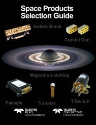
to view datasheet - Teledyne Coax Switches

You also want an ePaper? Increase the reach of your titles
YUMPU automatically turns print PDFs into web optimized ePapers that Google loves.
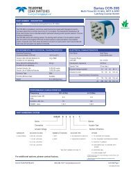
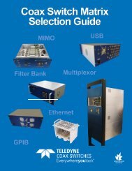
COAX SWITCHES<br />
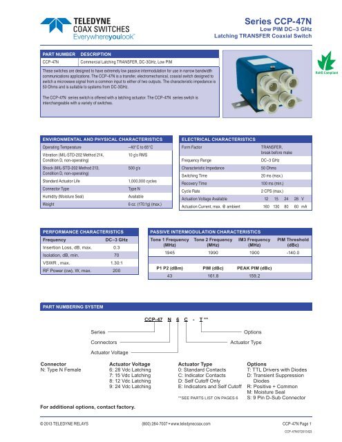
Series CCP-47N<br />
Low PIM DC–3 GHz<br />
Latching TRANSFER <strong>Coax</strong>ial Switch<br />
PART NUMBER<br />
CCP-47N<br />
DESCRIPTION<br />
Commercial Latching TRANSFER, DC-3GHz, Low PIM<br />
These switches are designed <strong>to</strong> have extremely low passive intermodulation for use in narrow bandwidth<br />
communications applications. The CCP-47N is a transfer, electromechanical, coaxial switch designed <strong>to</strong><br />
switch a microwave signal from a common input <strong>to</strong> either of two outputs. The characteristic impedance is<br />
50 Ohms and is suitable <strong>to</strong> systems from DC-3GHz.<br />
The CCP-47N series switch is offered with a latching actua<strong>to</strong>r. The CCP-47N series switch is<br />
interchangeable with a variety of switches.<br />
ENVIRONMENTAL AND PHYSICAL CHARACTERISTICS<br />
Operating Temperature –40°C <strong>to</strong> 65°C<br />
Vibration (MIL-STD-202 Method 214,<br />
10 g’s RMS<br />
Condition D, non-operating)<br />
Shock (MIL-STD-202 Method 213,<br />
500 g’s<br />
Condition D, non-operating)<br />
Standard Actua<strong>to</strong>r Life<br />
1,000,000 cycles<br />
Connec<strong>to</strong>r Type<br />
Type N<br />
Humidity (Moisture Seal)<br />
Available<br />
Weight<br />
6 oz. (170.1g) (max.)<br />
ELECTRICAL CHARACTERISTICS<br />
Form Fac<strong>to</strong>r<br />
TRANSFER,<br />
break before make<br />
DC–3 GHz<br />
50 Ohms<br />
20 ms (max.)<br />
100 ms (min.)<br />
2 CPS (max.)<br />
Frequency Range<br />
Characteristic Impedance<br />
Switching Time<br />
Recovery Time<br />
Cycle Rate<br />
Actuation Voltage Available 12 15 24 28 V<br />
Actuation Current, max. @ ambient 160 130 80 60 mA<br />
PERFORMANCE CHARACTERISTICS<br />
Frequency<br />
DC–3 GHz<br />
Insertion Loss, dB, max. 0.3<br />
Isolation, dB, min. 70<br />
VSWR , max. 1.30:1<br />
RF Power (cw), W, max. 200<br />
PASSIVE INTERMODULATION CHARACTERISTICS<br />
Tone 1 Frequency<br />
(MHz)<br />
Tone 2 Frequency<br />
(MHz)<br />
IM3 Frequency<br />
(MHz)<br />
PIM Threshold<br />
(dBc)<br />
1945 1990 1900 -140.0<br />
P1 P2 (dBm) PIM (dBc) PEAK PIM (dBc)<br />
43 161.8 159.2<br />
PART NUMBERING SYSTEM<br />
CCP-47 N 6 C - T **<br />
Series<br />
Connec<strong>to</strong>rs<br />
Options<br />
Actua<strong>to</strong>r Type<br />
Connec<strong>to</strong>r<br />
N: Type N Female<br />
Actua<strong>to</strong>r Voltage<br />
Actua<strong>to</strong>r Voltage<br />
6: 28 Vdc Latching<br />
7: 15 Vdc Latching<br />
8: 12 Vdc Latching<br />
9: 24 Vdc Latching<br />
For additional options, contact fac<strong>to</strong>ry.<br />
Actua<strong>to</strong>r Type<br />
0: Standard Contacts<br />
C: Indica<strong>to</strong>r Contacts<br />
D: Self Cu<strong>to</strong>ff Only<br />
E: Indica<strong>to</strong>rs and Self Cu<strong>to</strong>ff<br />
**SEE PARTS LIST ON PAGES 6<br />
Options<br />
T: TTL Drivers with Diodes<br />
D: Transient Suppression<br />
Diodes<br />
R: Positive + Common<br />
M: Moisture Seal<br />
S: 9 Pin D-Sub Connec<strong>to</strong>r<br />
© 2013 TELEDYNE RELAYS (800) 284-7007 • www.teledynecoax.com CCP-47N Page 1<br />
CCP-47N\072013\Q3
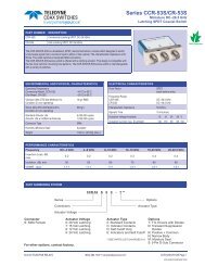
Series CCP-47N<br />
Low PIM DC–3 GHz<br />
Latching TRANSFER <strong>Coax</strong>ial Switch<br />
COAX SWITCHES<br />
SCHEMATICS AND MECHANICAL OUTLINE<br />
“-S OPTION” 9-PIN D-SUB CONNECTOR (EXAMPLE: CCP-47N60-S)<br />
9 PIN D-SUB PINOUT FOR LATCHING TRANSFER<br />
OPTIONS<br />
Pin<br />
Indica<strong>to</strong>rs &<br />
Basic Indica<strong>to</strong>rs TTL<br />
No.<br />
TTL<br />
1 1 1<br />
2 2 2<br />
3 C C Common Common<br />
4 1 1<br />
5 2 2<br />
6 Vsw Vsw<br />
7 A A<br />
8 B B<br />
9 C C<br />
TRUTH TABLE (with TTL option)<br />
Logic Input<br />
RF Path<br />
Indica<strong>to</strong>r<br />
(if applicable)<br />
1 2 1-2 1-3 2-4 3-4 A B<br />
0 0 No Change N/A<br />
1 0 Off On On Off A & C<br />
0 1 On Off Off On B & C<br />
1 1 Forbidden N/A<br />
CCP-47N Page 2 SPECIFICATIONS ARE SUBJECT TO CHANGE WITHOUT NOTICE © 2013 TELEDYNE COAX SWITCHES<br />
CCP-47N\072013\Q3
COAX SWITCHES<br />
Series CCP-47N<br />
Low PIM DC–3 GHz<br />
Latching TRANSFER <strong>Coax</strong>ial Switch<br />
TYPICAL NARROWBAND RF INSERTION LOSS PERFORMANCE CURVES<br />
0.00<br />
Insertion Loss (DC-3 GHz)<br />
-0.05<br />
Insertion Los (dB)<br />
-0.10<br />
-0.15<br />
-0.20<br />
-0.25<br />
0.0 0.5 1.0 1.5 2.0 2.5 3.0<br />
Frequency (GHz)<br />
Isolation (dB)<br />
Isolation (DC-3 GHz)<br />
0<br />
-10<br />
-20<br />
-30<br />
-40<br />
-50<br />
-60<br />
-70<br />
-80<br />
-90<br />
-100<br />
-110<br />
-120<br />
-130<br />
-140<br />
0.0 0.5 1.0 1.5 2.0 2.5 3.0<br />
Frequency (GHz)<br />
1.50<br />
VSWR (DC-3 GHz)<br />
1.45<br />
1.40<br />
1.35<br />
VSWR (dB)<br />
1.30<br />
1.25<br />
1.20<br />
1.15<br />
1.10<br />
1.05<br />
1.00<br />
0.0 0.5 1.0 1.5 2.0 2.5 3.0<br />
Frequency (GHz)<br />
RF NOTES<br />
© 2013 TELEDYNE RELAYS (800) 284-7007 • www.teledynecoax.com CCP-47N Page 3<br />
CCP-47N\072013\Q3
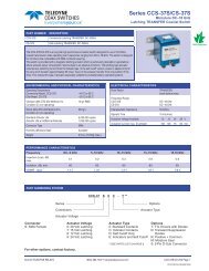
Series CCP-47N<br />
Low PIM DC–3 GHz<br />
Latching TRANSFER <strong>Coax</strong>ial Switch<br />
COAX SWITCHES<br />
TYPICAL POWER PERFORMANCE CURVE<br />
Power Handling vs. Frequency<br />
3000<br />
2000<br />
1000<br />
800<br />
600<br />
400<br />
STANDARD N SWITCHES<br />
Power (W)<br />
300<br />
200<br />
100<br />
80<br />
60<br />
40<br />
30<br />
20<br />
10<br />
.1 .2 .3 .4 .6 .8 1 2<br />
3<br />
Frequency GHz<br />
Estimates based on the following reference conditions:<br />
• Ambient temperature of 40°C or less<br />
• Sea level operation<br />
• Load VSWR of 1.30:1 maximum<br />
• No high-power (hot) switching<br />
Please contact <strong>Teledyne</strong> <strong>Coax</strong> <strong>Switches</strong> for derating fac<strong>to</strong>rs when applications do not meet the foregoing reference conditions.<br />
CCP-47N Page 4 SPECIFICATIONS ARE SUBJECT TO CHANGE WITHOUT NOTICE © 2013 TELEDYNE COAX SWITCHES<br />
CCP-47N\072013\Q3
COAX SWITCHES<br />
Series CCP-47N<br />
Low PIM DC–3 GHz<br />
Latching TRANSFER <strong>Coax</strong>ial Switch<br />
GLOSSARY<br />
Actua<strong>to</strong>r<br />
An actua<strong>to</strong>r is the electromechanical mechanism that<br />
transfers the RF contacts from one position <strong>to</strong> another upon<br />
DC command.<br />
Arc Suppression Diode<br />
A diode is connected in parallel with the coil. This diode<br />
limits the “reverse EMF spike” generated when the coil deenergizes<br />
<strong>to</strong> 0.7 volts. The diode cathode is connected <strong>to</strong><br />
the positive side of the coil and the anode is connected <strong>to</strong><br />
the negative side.<br />
Date Code<br />
All switches are marked with either a unique serial number<br />
or a date code. Date codes are in accordance with MIL-<br />
STD-1285 Paragraph 5.2.5 and consist of four digits.<br />
The fi rst two digits defi ne the year and the last two digits<br />
defi ne the week of the year (YYWW). Thus, 1032 identifi es<br />
switches that passed through fi nal inspection during the<br />
32nd week of 2010.<br />
Latching<br />
A latching switch remains in the selected position whether<br />
or not voltage is maintained. This can be accomplished<br />
with either a magnetic or mechanical latching mechanism.<br />
Indica<strong>to</strong>r<br />
Indica<strong>to</strong>rs tell the system which position the switch is in.<br />
Other names for indica<strong>to</strong>rs are telemetry contacts or tellback<br />
circuit. Indica<strong>to</strong>rs are usually a set of internally mounted DC<br />
contacts linked <strong>to</strong> the actua<strong>to</strong>r. They can be wired <strong>to</strong> digital<br />
input lines, status lights, or interlocks. Unless otherwise<br />
specifi ed, the maximum indica<strong>to</strong>r contact rating is 30 Vdc,<br />
50 mA, or 1.5 Watts in<strong>to</strong> a resistive load.<br />
Isolation<br />
Isolation is the measure of the power level at the output<br />
connec<strong>to</strong>r of an unconnected RF channel as referenced <strong>to</strong><br />
the power at the input connec<strong>to</strong>r. It is specifi ed in dB below<br />
the input power level.<br />
Self-Cu<strong>to</strong>ff<br />
The self-cu<strong>to</strong>ff option disables the actua<strong>to</strong>r current on<br />
completion of actuation. Either a series contact (linked<br />
<strong>to</strong> the actua<strong>to</strong>r) or an IC driver circuit provides the current<br />
cu<strong>to</strong>ff. This option results in minimum power consumption<br />
by the RF switch. Cutthroat is another name used in the<br />
industry for this option. Pulse latching is a term used <strong>to</strong><br />
describe a switch without this feature.<br />
TRANSFER Switch<br />
A four-port switch consisting of two independent pairs of<br />
RF paths. These pairs are actuated simultaneously. This<br />
actuation is similar <strong>to</strong> that of a double-pole double-throw<br />
switch.<br />
Switching Time<br />
Switching time is the <strong>to</strong>tal interval beginning with the arrival<br />
of the leading edge of the command pulse at the switch DC<br />
input and ending with the completion of the switch transfer,<br />
including contact bounce. It consists of three parts: (1)<br />
inductive delay in the coil, (2) transfer time of the physical<br />
movement of the contacts, and (3) the bounce time of the<br />
RF contacts.<br />
TTL Switch Driver Option<br />
As a special option, switch drivers can be provided for both<br />
failsafe and latching switches, which are compatible with<br />
industry-standard low-power Schottky TTL circuits.<br />
Performance Parameters vs Frequency<br />
Generally speaking, the RF performance of coaxial switches<br />
is frequency dependent. With increasing frequency, VSWR<br />
and insertion loss increase while isolation decreases. All<br />
data sheets specify these three parameters as “worst case”<br />
at the highest operating frequency. If the switch is <strong>to</strong> be<br />
used over a narrow frequency band, better performance<br />
can be achieved.<br />
Actua<strong>to</strong>r Current vs Temperature<br />
The resistance of the actua<strong>to</strong>r coil varies as a function of<br />
temperature. There is an inverse relationship between the<br />
operating temperature of the switch and the actua<strong>to</strong>r drive<br />
current. For switches operating at 28 VDC, the approximate<br />
actua<strong>to</strong>r drive current at temperature, T, can be calculated<br />
using the equation:<br />
I T<br />
=<br />
Where:<br />
I A<br />
[1 + .00385 (T-20)]<br />
I T<br />
= Actua<strong>to</strong>r current at temperature, T<br />
I A<br />
= Room temperature actua<strong>to</strong>r current –<br />
see data sheet<br />
T = Temperature of interest in °C<br />
Magnetic Sensitivity<br />
An electro-mechanical switch can be sensitive <strong>to</strong> ferrous<br />
materials and external magnetic fi elds. Neighboring ferrous<br />
materials should be permitted no closer than 0.5 inches and<br />
adjacent external magnetic fi elds should be limited <strong>to</strong> a fl ux<br />
density of less than 5 Gauss.<br />
SPECIAL FEATURE<br />
Switching High-Power or Highly Sensitive Signals<br />
Ensure the most linear response with the best galvanically<br />
matched contact system in the industry. Extremely low<br />
passive intermodulation is standard on all of our switches.<br />
Carrier<br />
Frequency 1<br />
Carrier<br />
Frequency 2<br />
PIM 3rd Order<br />
Frequency<br />
PIM 5th<br />
Order Frequency<br />
870 MHz 893 MHz 847 MHz 824 MHz<br />
Transfer<br />
3rd Order<br />
Intermodulation<br />
5th Order<br />
Intermodulation<br />
–103 dBm –123 dBm<br />
–146 dBc –165 dBc<br />
© 2013 TELEDYNE RELAYS (800) 284-7007 • www.teledynecoax.com CCP-47N Page 5<br />
CCP-47N\072013\Q3
Series CCP-47N<br />
Low PIM DC–3 GHz<br />
Latching TRANSFER <strong>Coax</strong>ial Switch<br />
COAX SWITCHES<br />
LATCHING CCP-47N PART NUMBER LIST<br />
PART NO.<br />
PART NO.<br />
1 CCP-47NXC 43 CCP-47NX0<br />
2 CCP-47NXC-D 44 CCP-47NX0-D<br />
3 CCP-47NXC-DM 45 CCP-47NX0-DM<br />
4 CCP-47NXC-DMS 46 CCP-47NX0-DMS<br />
5 CCP-47NXC-DR 47 CCP-47NX0-DR<br />
6 CCP-47NXC-DRM 48 CCP-47NX0-DRM<br />
7 CCP-47NXC-DRMS 49 CCP-47NX0-DRMS<br />
8 CCP-47NXC-DRS 50 CCP-47NX0-DRS<br />
9 CCP-47NXC-DS 51 CCP-47NX0-DS<br />
10 CCP-47NXC-M 52 CCP-47NX0-M<br />
11 CCP-47NXC-MS 53 CCP-47NX0-MS<br />
12 CCP-47NXC-R 54 CCP-47NX0-R<br />
13 CCP-47NXC-RM 55 CCP-47NX0-RM<br />
14 CCP-47NXC-RMS 56 CCP-47NX0-RMS<br />
15 CCP-47NXC-RS 57 CCP-47NX0-RS<br />
16 CCP-47NXC-S 58 CCP-47NX0-S<br />
17 CCP-47NXC-T 59 CCP-47NX0-T<br />
18 CCP-47NXC-TM 60 CCP-47NX0-TM<br />
19 CCP-47NXC-TMS 61 CCP-47NX0-TMS<br />
20 CCP-47NXC-TS 62 CCP-47NX0-TS<br />
21 CCP-47NXD<br />
22 CCP-47NXD-M<br />
23 CCP-47NXD-MS<br />
24 CCP-47NXD-R<br />
25 CCP-47NXD-RM<br />
26 CCP-47NXD-RMS<br />
27 CCP-47NXD-RS<br />
28 CCP-47NXD-S<br />
29 CCP-47NXD-T<br />
30 CCP-47NXD-TM<br />
31 CCP-47NXD-TMS<br />
32 CCP-47NXE<br />
33 CCP-47NXE-M<br />
34 CCP-47NXE-MS<br />
35 CCP-47NXE-R<br />
36 CCP-47NXE-RM<br />
37 CCP-47NXE-RMS<br />
38 CCP-47NXE-RS<br />
39 CCP-47NXE-S<br />
40 CCP-47NXE-T<br />
41 CCP-47NXE-TM<br />
42 CCP-47NXE-TMS<br />
* X = 6 (28Vdc), 7 (15Vdc), 8 (12Vdc) and 9 (24Vdc)<br />
CCP-47N Page 6 SPECIFICATIONS ARE SUBJECT TO CHANGE WITHOUT NOTICE © 2013 TELEDYNE COAX SWITCHES<br />
CCP-47N\072013\Q3