Download our Space Databook - Teledyne Relays
Download our Space Databook - Teledyne Relays
Download our Space Databook - Teledyne Relays

You also want an ePaper? Increase the reach of your titles
YUMPU automatically turns print PDFs into web optimized ePapers that Google loves.
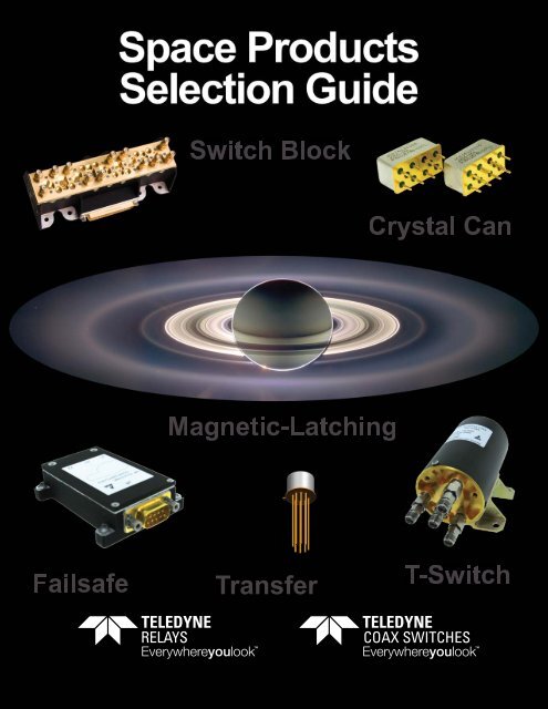
COAX SWITCHES
www.teledynerelays.com<br />
<strong>Teledyne</strong>’s electromechanical switch product line consists of a variety of switches designed for commercial, defense, and<br />
space applications. Our space-qualified product line consists of TO-5 electromechanical relays, coaxial switches, switch<br />
matrices, and switch blocks. These products may be custom-designed and manufactured according to specific<br />
performance requirements. <strong>Teledyne</strong> also provides a complete line of standard, off-the-shelf, high-reliability switches that<br />
offers its customers significant cost savings, while satisfying most critical requirements for scientific, meteorological, and<br />
communication satellite applications.<br />
Through numerous challenges over the past 50 years,<br />
<strong>Teledyne</strong> has developed and established a complete line<br />
of space qualified switches for high-power applications in<br />
L, S, C, KU, and K bands.<br />
<strong>Teledyne</strong>’s fully equipped laboratories are certified for the<br />
development and production of space-qualified coaxial<br />
switches, and support several large switch production<br />
programs.<br />
Product Assurance<br />
Under an aggressive Total Quality Management (TQM) program, <strong>Teledyne</strong> has embraced a “continuous improvement”<br />
culture. With recognized certifications such as Boeing D1-9000, DSCC MIL-STD-790, and ISO 9001/9002, <strong>Teledyne</strong> has<br />
become a primary supplier of switching solutions with the highest quality and reliability to industry leaders around the world.<br />
Product Development<br />
<strong>Teledyne</strong> offers a full range of comprehensive switching solutions. In addition to offering standard switching solutions,<br />
<strong>our</strong> experienced team works closely with <strong>our</strong> customers to develop tailored products for specific applications. We offer<br />
advanced engineering, state-of-the-art manufacturing techniques, and over 50 years of switching experience with a<br />
commitment to quality, costs and delivery.<br />
Technical Service & Customer Support<br />
<strong>Teledyne</strong> provides easy access to technical service and customer support. Our website makes it easy to find technical<br />
information, buy products and e-mail responses within 24 h<strong>our</strong>s. Switching solutions are only a mouse click away at<br />
www.teledynerelays.com.<br />
SPECIFICATIONS SUBJECT TO CHANGE WITHOUT NOTICE<br />
© 2013 <strong>Teledyne</strong> <strong>Relays</strong>
COAX SWITCHES<br />
www.teledynecoax.com<br />
For over fifty years <strong>Teledyne</strong> <strong>Relays</strong> has been supplying high reliability switching solutions intended for space flight<br />
applications. As the inventor of the ultra-miniature T0-5 electromechanical relay <strong>Teledyne</strong> <strong>Relays</strong> has been involved with<br />
all facets of the modern space age. From the earliest NASA missions <strong>Teledyne</strong> <strong>Relays</strong> has supplied T0-5 relays and RF<br />
Coax Switches for use in all type of space craft: manned, unmanned, deep space and robotic exploration.<br />
<strong>Teledyne</strong> <strong>Relays</strong>’ early involvement in space flight applications has<br />
allowed for us to participate in many of the major accomplishments<br />
in manned space flight. Our electro-mechanical relays and RF Coax<br />
Switches have been, and are currently used in major launch vehicles;<br />
Delta III, Arian IV, Arian V and VEGA Programs.<br />
Additionally <strong>our</strong> relays are involved in near and deep space<br />
exploration, with electro-mechanical relays currently roaming the<br />
surface of Mars on both Rovers and on their way to the Red Planet<br />
on the Mars Science Lab. Our electro-mechanical relays are<br />
currently orbiting Saturn aboard the Cassini <strong>Space</strong>craft and <strong>our</strong> RF<br />
Coaxial Switches are on their way to Pluto aboard the<br />
New Horizons space craft.<br />
In addition to <strong>our</strong> participation in un-manned programs we have<br />
supplied <strong>our</strong> Hi-Rel Products for use on manned programs. Our<br />
electro-mechanical relays are used in various components of the<br />
International <strong>Space</strong> Station and <strong>our</strong> RF Coax Switches played<br />
a major part in the communication system of the <strong>Space</strong> Shuttle<br />
fleet.<br />
<strong>Space</strong> Market Segments Served:<br />
• Deep-space Probes<br />
• Manned Programs<br />
• Communiations Satellites<br />
• Launch Vehicles<br />
• Earth Observatory / Weather Satellites<br />
• Commercial/Military Satellites<br />
Capabilities:<br />
• Logistic Infrastructure<br />
• Chemical Analysis Lab<br />
• Scanning Electro Microscope (SEM)<br />
• In-house Plating Shop<br />
• Environmental Test Lab<br />
• Field Technical Support<br />
© 2013 <strong>Teledyne</strong> Coax Switches (800) 351-7368 • www.teledynerelays.com www.teledynecoax.com • +44 (0) 1236 453124 • www.teledyne-europe.com<br />
Page 3
<strong>Teledyne</strong> <strong>Space</strong> Products<br />
Page<br />
<strong>Space</strong> Products Introduction 2-3<br />
<strong>Space</strong> Products Overview 4-5<br />
<strong>Space</strong> Products Standards 6-7<br />
<strong>Space</strong> Products Capabilities 8-9<br />
TO-5 & Half-size Crystal Can <strong>Space</strong> Products<br />
HR/HRS 412 Series 10-12<br />
HR/HRS 412V Series 13-15<br />
HR/HRS 412K Series 16-18<br />
HR/HRS 422 Series 19-21<br />
HR/HRS 422K Series 22-24<br />
HR/HRS 255/257 Series 25-29<br />
EMR Test/Inspection Flow 29<br />
Detailed Summary of Standard Screening 30-33<br />
Arabsat 5C<br />
Page 4 SPECIFICATIONS SUBJECT TO CHANGE WITHOUT NOTICE<br />
© 2013 <strong>Teledyne</strong> <strong>Relays</strong>
Table of Contents<br />
Coaxial SPDT Switch <strong>Space</strong> Products<br />
COAX SWITCHES<br />
Page<br />
H33S Series 34-35<br />
H32N Series 36-37<br />
Coaxial Transfer Switch <strong>Space</strong> Products<br />
H37S Series 38-39<br />
H47N Series 40-41<br />
Coaxial T-Switch <strong>Space</strong> Products<br />
T-Switch Series 42-47<br />
ATP COAX Test Flow 48<br />
Detailed Summary of Standard Screening 49<br />
Coaxial Switch Block Assemblies for <strong>Space</strong><br />
CSM Series 50-51<br />
<strong>Teledyne</strong> <strong>Relays</strong> HIREL <strong>Space</strong> Products Program<br />
Lead Forming Options 52-53<br />
Facilities 54-55<br />
Glossary 56-57<br />
AsiaSat 7<br />
Globalstar 2<br />
BSAT-3A<br />
© 2013 <strong>Teledyne</strong> Coax Switches (800) 351-7368 • www.teledynerelays.com www.teledynecoax.com • +44 (0) 1236 453124 • www.teledyne-europe.com<br />
Page 1
<strong>Teledyne</strong> <strong>Space</strong><br />
With over forty years of supplying High Reliability (Hi-Rel) electromechanical relays (EMR) and RF<br />
Coaxial Switches for space applications <strong>Teledyne</strong> <strong>Relays</strong> has developed a High Reliability Program<br />
that provides the flexibility of ordering products within a structured and standardized approach. The<br />
High Reliability Program for relays is defined in the TR-HIREL-1 Specifications, which consist of a<br />
series of documents which define the performance and quality assurance provisions that govern<br />
<strong>Teledyne</strong> <strong>Relays</strong>’ high reliability designs. For RF Coaxial Switch requirements we have developed the<br />
General Specification for High Reliability RF Coax Switches, a predefined S<strong>our</strong>ce Control Drawing<br />
for the procurement of RF switches to be used in space applications. As with the TR-HIREL-1 this<br />
document fully defines the requirements for test and inspection, providing detailed information on test<br />
methodology and inspection criteria.<br />
Echostar<br />
The features and benefits of <strong>Teledyne</strong> <strong>Relays</strong>’ TR-HIREL-1 Program is that it employs the test<br />
methods and inspection criteria in a format compliant to current industry standards for the acquisition<br />
of High Reliability Switching Solutions, namely, NASA/GSFC S-311-P-754, NASA EEE-INST-002<br />
and ESA/SCC 3601 and 3602 Specifications. The TR-HIREL-1 contains various tables that list the<br />
Specifications under Configuration Control applicable to European <strong>Space</strong> Agency (ESA)and<br />
NASA/Goddard <strong>Space</strong> Flight Center requirements. The TR-HIREL-1 Specification Program contains<br />
test protocols that have been used extensively in High Reliability applications and fully define:<br />
configuration, limits, environmental profiles, life cycle expectations, and other key characteristics with<br />
the understanding of their impact on performance and associated reliability.<br />
Hylas 1<br />
Hylas 2<br />
Page 2 SPECIFICATIONS SUBJECT TO CHANGE WITHOUT NOTICE © 2013 <strong>Teledyne</strong> <strong>Relays</strong>
Product Introduction<br />
COAX SWITCHES<br />
Based on specific program requirements, quality assurance testing plans can also be tailored on<br />
a menu-based selection. This selection has been developed utilizing <strong>Teledyne</strong> <strong>Relays</strong>’ extensive<br />
experience in offering high reliability products for a wide variety of applications within the space<br />
community. Our products have been used on geosynchronous earth orbiting satellites (GEO), low<br />
earth orbiting (LEO) satellites, earth observation satellites (EOS), deep space exploration space craft,<br />
all of the Mars rovers and manned programs. Additional program heritage is as follows:<br />
Communication Satellites<br />
Globalstar TacSat 4<br />
Astra 1N<br />
Luch 5A<br />
AMC-5R Echostar 14<br />
YahSat<br />
RASCOM-QAF 1, 1R<br />
New Dawn<br />
AEHF (Advanced Extreme High Frequency Satellite)<br />
Arabsat 5C<br />
XM-5<br />
QuetzSat 1<br />
Eutelsat W3B<br />
Intelsat 18<br />
BSAT-3a<br />
AsiaSat 5, 7 SkyTerra 1, 2<br />
Amos 5<br />
HYLAS (Highly Adaptable Satellite).<br />
Hispasat 1E Koreasat 6 (Olleh 1)<br />
KA-SAT HOT BIRD 6<br />
ViaSat-1<br />
Anik F3<br />
Skynet 5<br />
Insat 4A, 4B<br />
Astra 1L Thuraya-2 and 3<br />
Thor 5<br />
WINDS (Kizuna)<br />
DirecTV 10, 11, 12<br />
Star One C1, C2<br />
VINASAT-1 Galaxy 16, 18<br />
Türksat 3A Superbird 7 (Superbird C2)<br />
AMC-21<br />
Inmarsat-4<br />
Alphasat I-XL DSCS-3 (Defense Satellite Communications System 3)<br />
SATMEX 5<br />
ETS 6 (Engineering Test Satellite)<br />
Insat 4G<br />
Artemis (Advanced Relay And Technology Mission)<br />
ABS-2<br />
MTSat (Multifunctional Transport Satellite)<br />
© 2013 <strong>Teledyne</strong> Coax Switches (800) 351-7368 • www.teledynerelays.com www.teledynecoax.com • +44 (0) 1236 453124 • www.teledyne-europe.com Page 3
<strong>Teledyne</strong> <strong>Space</strong><br />
Earth Observation/Remote Sensing Satellites<br />
GRACE<br />
GRAIL<br />
GOES N, O, P, Q<br />
SERVIS (<strong>Space</strong> Environment Reliability Verification Integrated System)<br />
COMS (Communication, Ocean and Meteorological Satellite)<br />
AlSat 2A, 2B<br />
SBSS (<strong>Space</strong>-Based <strong>Space</strong> Surveillance System)<br />
COSMO-SkyMed<br />
ASTRO (Autonomous <strong>Space</strong> Transport Robotic Operations satellite)<br />
GeoEye 1<br />
ICESAT (Ice, Cloud & Land Elevation Satellite),<br />
CHIPSat (Cosmic Hot Interstellar Plasma Spectrometer Satellite)<br />
Radarsat 1<br />
Oceansat 2<br />
IRS (Indian Remote Sensing Satellite)<br />
KOMPSat (Korean Multi-purpose Satellite)<br />
QuikScat (Quick Scatterometer)<br />
TOPEX/POSEIDON<br />
XM-5 1<br />
Deep <strong>Space</strong> Probes<br />
Juno (New Frontiers 2)<br />
Mars Science Laboratory (MSL, Curiosity)<br />
Mars Exploration Rovers<br />
Pathfinder<br />
Planet-C or VCO (Venus Climate Orbiter)<br />
Cassini<br />
Herschel/Planck<br />
Hubble <strong>Space</strong> Telescope<br />
New Horizons<br />
Manned Programs<br />
International <strong>Space</strong> Station Alpha (ISS)<br />
<strong>Space</strong> Shuttle (STS)<br />
Navigation Satellites<br />
Galileo-IOV<br />
GLONASS<br />
Global Positioning System (GPS)<br />
GIOVE B (Galileo In-Orbit Validation<br />
Element)<br />
Page 4 SPECIFICATIONS SUBJECT TO CHANGE WITHOUT NOTICE © 2013 <strong>Teledyne</strong> <strong>Relays</strong>
Product Overview<br />
COAX SWITCHES<br />
In addition to meeting the “basic” requirements of the NASA & ESA specifications the<br />
TR-HIREL-1has been configured to provide the user with additional environment test and inspections<br />
to satisfy application specific requirements associated with space flight missions. Additional<br />
tests contained within the TR-HIREL-1 are Vibration Miss Test (aka Miss Test Under Vibration &<br />
Asynchronous Miss Test)<br />
Specifications<br />
NASAS3IIP754<br />
NASA INST-EE<br />
ESASCS360I<br />
ESASCC3602<br />
TR-HIREL -1<br />
Certifications<br />
MILPRF39016<br />
ISO 9001: 2008<br />
NASA SOLDER<br />
BOEING D1-9000<br />
MIL-STD-790<br />
© 2013 <strong>Teledyne</strong> Coax Switches (800) 351-7368 • www.teledynerelays.com www.teledynecoax.com • +44 (0) 1236 453124 • www.teledyne-europe.com Page 5
<strong>Teledyne</strong> <strong>Space</strong><br />
The purpose in developing the TR-HIREL-1 Specification was to provide <strong>our</strong> customers with a generic<br />
specification meeting the basic requirements of the ESA/SCC 3001 & 3602 and the NASA/GSFC<br />
S-311-P-754 specifications. The “basic” test protocol is as follows:<br />
Required Tests<br />
100% Pre-Cap<br />
Small Particle<br />
Sinusoidal Vibration<br />
Random Vibration (when specifi ed)<br />
Resonant Beam Test (High Vibration “V” <strong>Relays</strong> Only)<br />
P.I.N.D. Test<br />
Internal Moisture<br />
Temperature Condition, High and Low Temperature Miss Test<br />
Electrical Measurements<br />
Leak Test<br />
Radiographic Inspection (X-Ray)<br />
Green Dot Marking<br />
Visual Inspection<br />
Page 6 SPECIFICATIONS SUBJECT TO CHANGE WITHOUT NOTICE © 2013 <strong>Teledyne</strong> <strong>Relays</strong>
Product Standards<br />
COAX SWITCHES<br />
The purpose of the TR-HIREL-1 is to provide the user with an established, pre-formatted specification<br />
meeting the requirements of the NASA/GSFC S311-P-754, European <strong>Space</strong> Agency (ESA)<br />
Specification SCC/3601 & 3601 and the latest NASA Document EEE-INST-002, Instructions for EEE<br />
Parts Selection, Screening, Qualification and Derating. The default requirements of the TR-HIREL<br />
meet all three referenced specifications with the following “Final Production Tests” and “Screening and<br />
Electrical Measurements”:<br />
100% Pre-cap inspection - Criteria establishing the standard methods for inspection prior to hermetic<br />
sealing (<strong>Teledyne</strong> <strong>Relays</strong>’ Procedure of Internal Inspection, Document 0-40-115)<br />
Small Particle Inspection/Millipore Clean - in-process inspection to further evaluate relay cleanliness<br />
Through an automated small particle inspection process prior to sealing (<strong>Teledyne</strong> <strong>Relays</strong>’ Pre-cap<br />
Small Particle Inspection, Document 0-40-265)<br />
Sinusoidal Vibration - Standard Vibration test, sinusoidal and random, as specified by MIL-PRF-39016<br />
& MIL-PRF-28776 (MIL-STD-202, Method 204; Test Method: Vibration, High Frequency)<br />
Particle Impact Noise Detection (P.IN.D.) -This test is designed to detect the presence of loose<br />
particles in sealed relays. This test method meets the criteria of MIL-R-39016E, Appendix B*<br />
(<strong>Teledyne</strong> <strong>Relays</strong>’ Particle Impact Noise Detection, Document 0-40-824)<br />
Temperature Conditioning & High and Low Temperature Miss Test - Internal Moisture and High and<br />
Low Temperature Run-In tests per the requirement of MIL-PRF-39016 & MIL-PRF-28776<br />
(MIL-STD-202, Method 107 Test Method: Thermal Shock)<br />
Room Temperature Miss Test - <strong>Relays</strong> shall be subjected to a 2,500 cycle run-in test at<br />
applicable ambient temperatures. (MIL-PRF-39016)<br />
Electrical Measurements - used to prove that the component part can operate safely at its rated<br />
voltage (MIL-PRF-39016 & MIL-STD-202)<br />
© 2013 <strong>Teledyne</strong> Coax Switches (800) 351-7368 • www.teledynerelays.com www.teledynecoax.com • +44 (0) 1236 453124 • www.teledyne-europe.com Page 7
<strong>Teledyne</strong> <strong>Space</strong><br />
Leak/Seal Test The purpose of this test method is to determine the effectiveness of the seal of a<br />
component part which has an internal cavity which is either evacuated or contains air or gas there shall<br />
be no leakage in excess of1 × 10–8 atm-cm3/s of air.<br />
(MIL-STD-202, Method 112 Test Method: Seal)<br />
Radiographic Inspection (X-ray) Each relay shall be examined to determine proper internal<br />
construction and workmanship. <strong>Teledyne</strong> <strong>Relays</strong>’ Radiographic Inspection of <strong>Relays</strong>, Document<br />
No. 0-40-193<br />
External Visual and Mechanical Inspection <strong>Relays</strong> shall be examined to verify that the marking, header<br />
glass, external design and construction, physical dimensions and workmanship are in accordance<br />
with <strong>Teledyne</strong> <strong>Relays</strong>’ acceptance criteria. <strong>Teledyne</strong> <strong>Relays</strong>’ Inspection Criteria, External Visual and<br />
Mechanical, Document 0-40-913.<br />
The TR-HIREL-1 specification is a guideline to aid in the procurement of electromechanical relays<br />
furnished to meet the requirements of all applicable electro-mechanical specifications:<br />
• MIL-PRF-39016<br />
• MIL-PRF-28776<br />
• NASA/GSFC S-311-P-754<br />
• NASA EEE-INST-002<br />
• ESA/SCC 3601<br />
• ESA/SCC 3602<br />
The TR-HIREL-1 provides an efficient cost effective alternative to the requirements for S<strong>our</strong>ce Control<br />
Drawings (SCD) and the cycle of specification reviews associated with them. The TR-HIREL-1 has the<br />
heritage and credibility of worldwide recognition and use in every facet of the space community. <strong>Relays</strong><br />
screened in accordance with the TR-HIREL-1 are currently in use on communications satellites, deep<br />
space probes and launch vehicles. The specification has been embraced on an international level<br />
because of its ability to satisfy NASA and ESA requirements with its default requirements. In addition<br />
to being used as a stand-alone procurement specification the TR-HIREL-1 has been used as the<br />
baseline for customer SCD’s.<br />
Page 8 SPECIFICATIONS SUBJECT TO CHANGE WITHOUT NOTICE © 2013 <strong>Teledyne</strong> <strong>Relays</strong>
Product Capabilities<br />
COAX SWITCHES<br />
<strong>Teledyne</strong> <strong>Relays</strong>’ TR-HIREL-1 High Reliability Specification<br />
For over Fifty years <strong>Teledyne</strong> <strong>Relays</strong> has been supplying High Reliability relays to the aerospace<br />
community for use in space flight applications. Drawing on this experience we have developed the<br />
TR-HIREL-1 Specification Program. This Program provides <strong>our</strong> customers with the means to order high<br />
reliability switching solutions to established specification which define the performance requirements in<br />
addition to the governing quality assurance provisions. The TR-HIREL-1 Program consists of a series of<br />
documents which define the performance and quality assurance provisions comparable to those<br />
defined in:<br />
NASA/GSFC S-311-P-754<br />
NASA EE-INST-002<br />
ESA/SCC 3601<br />
ESA/SCC 3602<br />
Design control and configuration control activities are conducted as prescribed by recognized industry<br />
standards such as ISO 9001, Boeing AS9000 and MIL-STD-709.<br />
The TR-HIREL -1 Specification provides for the customization of test plans to assist the user in verifying<br />
the functionality of the product procured before installation into higher level assemblies. Verification can<br />
be achieved by any combination of the following:<br />
• Custom qualification plans jointly developed by <strong>Teledyne</strong> <strong>Relays</strong> and the customer.<br />
• Review of existing historical data compiled from similar designs.<br />
• Custom selection of test and inspection variants during Production Lot manufacture.<br />
• Menu driven Lot Acceptance Tests based on MIL-PRF-39016 & ESA/SCC requirements.<br />
For more information, or assistance in the application of the TR-HIREL-1 Program, please contact y<strong>our</strong><br />
regional Sales Manager:<br />
Asia Regional Manager United States & Canada Europe<br />
Michael Lim Dan Yracheta Olivier Dilun<br />
+65-81279247 12525 Daphne Ave. European Director Sales<br />
Singapore, 658363 Hawthorne, California 90250-3384 and Marketing acting as<br />
E-mail: mlim@teledyne.com Phone: 323.241.1218 Fax: 323.241.1287 Regional Sales Manager for<br />
Cell: 310.717.3600<br />
E-mail: dyracheta@teledyne.com<br />
Benelux, Eastern Europe,<br />
France, Italy, Scandinavia<br />
Tel: +33 (0) 1-6405-8118<br />
E-mail: dilun@teledyne.com<br />
© 2013 <strong>Teledyne</strong> Coax Switches (800) 351-7368 • www.teledynerelays.com www.teledynecoax.com • +44 (0) 1236 453124 • www.teledyne-europe.com Page 9
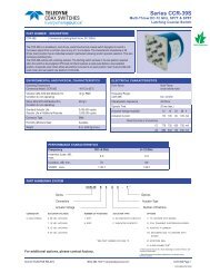
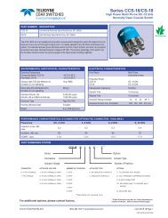
Series HR412/HRS412<br />
DC up to 1 GHz<br />
Non-Latching <strong>Space</strong> Grade DPDT Relay<br />
PART NUMBER<br />
HR412<br />
HRS412<br />
DESCRIPTION<br />
Non-Latching, DPDT, TO-5 <strong>Space</strong> Grade Relay (HIREL)<br />
Non-Latching, DPDT, TO-5 <strong>Space</strong> Grade Relay (HIREL), Surface Mount J-Leads<br />
<strong>Teledyne</strong> <strong>Relays</strong>’ HR/HRS412 Series relay is a High Reliability Off-The Shelf relay suitable for<br />
demanding space flight applications. When purchased in accordance with <strong>Teledyne</strong> <strong>Relays</strong>’ standard<br />
Hi-Rel Acceptance Test Procedure (ATP) the relays will meet the basic requirements of both the NASA<br />
Goddard <strong>Space</strong> Flight Center’s S-311-P-754 Document and the European <strong>Space</strong> Agency’s (ESA) SCC<br />
3601 & 3602 Specifications. The HR/HRS412 Series has become the premier selection for space flight<br />
applications requiring low-level switching to dry circuits up to 1 Amp. <strong>Teledyne</strong> <strong>Relays</strong>’ 50 year history of<br />
supplying relays to the spacecraft manufacturing community has supported 95% of all satellite programs<br />
worldwide. <strong>Relays</strong> may be supplied in accordance with the standard requirements of the Hi-Rel ATP or<br />
as specified by customer s<strong>our</strong>ce control drawings. In addition to enhanced test and inspection at the<br />
relay level the individual piece parts are inspected to higher standards. Relay leads may be supplied in<br />
either gold (Au) or solder dipped finish. A variety of formed lead configurations performed by the factory<br />
are available. All Hi-Rel relays are supplied with full data packages in either hard copy or electronic<br />
format. Customer S<strong>our</strong>ce Inspection (CSI) may be performed during critical manufacturing and test<br />
points.<br />
HR/HRS412 HIREL SERIES OVERVIEW<br />
Design Based on QPL-Approved MIL-PRF-39016 Specification<br />
Proven <strong>Space</strong> Flight Heritage<br />
Meets the general requirements of NASA/GSFC, S311-P-754<br />
Meets the general requirements of ESA/SCC General Specification 3601 & 3602<br />
1x10 -8 Leak Rate<br />
Standard Acceptance Test Procedure (ATP) Meets both ESA and NASA Requirements<br />
MIL-DTL-45204 Gold Plating<br />
ANSI-J-STD-006 Requirements for Electric Grade Solder Alloys and Fluxed and Non-Fluxed Sold Solders for Electronic Soldering Applications<br />
100% Small Particle/ Inspection (Millipore Cleaning)<br />
STANDARD HIREL SCREENING<br />
100% Pre-Cap Inspection (S<strong>our</strong>ce Inspection Available) Particle Impact Noise Detection (PIND)<br />
Room Temperature Electrical Measurements<br />
Internal Moisture<br />
Solderability<br />
Thermal Cycle/Miss Test (5,000 cycles total) + 2,500 at Room Temperature<br />
Leak/Seal Test (1x10 -8 ) CC/sec<br />
Room Temperature Electrical Measurements<br />
External Visual & Mechanical<br />
Radiographic Inspection (X-Ray)<br />
Vibration, Sinusoidal (30 G’s) Percent Defect Allowable, failure rate of lot (less than 10%)<br />
ENVIRONMENTAL AND PHYSICAL CHARACTERISTICS<br />
Form Factor 2 Form C (DPDT) Operating Temperature –65°C to +125°C<br />
Frequency Range DC-1 GHz Vibration (Sinusoidal) 30 g’s 10 to 2500 Hz<br />
Lead Finish Gold Plated or Solder Coated Shock (Specific Pulse)<br />
100 g’s,<br />
6ms half sine<br />
Hermetic Seal 1 x 10 -8 atm-cm 3 /s Weight 0.09 oz. (2.55) max.<br />
Page 10 SPECIFICATIONS SUBJECT TO CHANGE WITHOUT NOTICE © 2013 <strong>Teledyne</strong> <strong>Relays</strong>
Series HR412/ HRS412<br />
DC up to 1 GHz<br />
Non-Latching <strong>Space</strong> Grade DPDT Relay<br />
Contact Load and Life Ratings<br />
LOAD LEVEL CONTACT LOAD CONTACT LIFE<br />
Low level/Mechanical<br />
10 – 50 μA at 10 – 50 mV d.c. orpeak a.c.<br />
100,000 cycles rated life<br />
1,000,000 cycles unmonitored<br />
(Mechanical Life)<br />
Intermediate Current 100mA at 28Vdc 50,000 cycles<br />
High Level, Resistive 1.0A at 28Vdc 100,000 cycles<br />
High Level, Inductive 200mA at 28Vdc, with 0.32H inductance 100,000 cycles<br />
High Level, Lamp 100mA at 28Vdc 100,000 cycles<br />
Overload, Resistive 2.0A at 28Vdc 100 cycles<br />
Specifi cations based on relay case being grounded, unless otherwise specifi ed<br />
Static Contact Resistance or Voltage Drop<br />
Maximum Static Contact Resistance or Voltage Drop<br />
Measurement Condition<br />
Low Level Life<br />
Intermediate<br />
Current<br />
High Level Life<br />
Overload<br />
Without attached<br />
spacer/spreader pad<br />
With M4 spacer pad<br />
attached<br />
With M/M3 spreader<br />
pad attached<br />
With M2 spreader<br />
pad attached<br />
Initial 0.100Ω 0.110Ω 0.125Ω 0.150Ω<br />
During test<br />
After 100,000 or<br />
1,000,000 cycle life<br />
33Ω (1.65mVdc monitoring Level)<br />
0.150Ω 0.160Ω 0.175Ω 0.200Ω<br />
During test<br />
1Ω (100mVdc monitoring Level)<br />
After 50,000 0.200Ω 0.210Ω 0.225Ω 0.250Ω<br />
During life<br />
After 100,000 cycle<br />
life<br />
During test<br />
After 100,000 cycle<br />
life<br />
Voltage drop no more than 5% of open circuit voltage (1.4 Vdc monitoring level)<br />
0.200Ω 0.210Ω 0.225Ω 0.250Ω<br />
Not Monitored<br />
0.200Ω 0.210Ω 0.225Ω 0.250Ω<br />
General Electrical Specifications<br />
Insulation Resistance<br />
Dielectric Strength<br />
Operate Time<br />
Release Time<br />
Release Time (with diode)<br />
Negative Coil Transient (Vdc)<br />
Block Integrity max. leakage<br />
current<br />
Breakdown Voltage<br />
10,000 MΩ minimum at 500Vdc<br />
1,000MΩ minimum at 500Vdc between coil and case at +125°C<br />
1,000MΩ minimum at 500Vdc after 100 cycle overload<br />
100,000 cycle high life, or 50,000 intermediate current tests<br />
500Vrms ±5% at 50 or 60Hz<br />
375Vrms at 50 or 60Hz after 100 cycle overload, 100,000 cycle high level life, or<br />
50,000 intermediate current tests<br />
2.0 ms maximum with rated coil voltage<br />
1.5 ms maximum from rated coil voltage<br />
4.0 ms maximum from rated coil voltage<br />
1.0 max.<br />
1μA at 50Vdc<br />
100Vdc min. at 10μA<br />
© 2013 <strong>Teledyne</strong> Coax Switches (800) 351-7368 • www.teledynerelays.com • +44 (0) 1236 453124 • www.teledyne-europe.com Page 11
Series HR412/HRS412<br />
DC up to 1 GHz<br />
Non-Latching <strong>Space</strong> Grade DPDT Relay<br />
Coil Data and Operating Characteristics of Basic <strong>Relays</strong> and <strong>Relays</strong> with optional Diode for Coil Transient Suppression<br />
Coil Voltage (Vdc) Room Ambient Temperature (+25°C) Over Temperature Range<br />
Rated<br />
Max<br />
Coil Resistance (Ω)<br />
±10%<br />
Pick-Up<br />
Voltage (Vdc)<br />
max.<br />
Hold Voltage<br />
(Vdc) max.<br />
Drop-Out<br />
Voltage (Vdc)<br />
max.<br />
Pick-Up<br />
Voltage (Vdc)<br />
max.<br />
Hold Voltage<br />
(Vdc) max.<br />
Drop-Out<br />
Voltage (Vdc)<br />
max.<br />
5.0 5.8 50 2.7 1.4 0.22 3.5 2.3 0.14<br />
6.0 8.0 98 3.5 2.0 0.28 4.5 3.2 0.18<br />
9.0 12.0 220 5.3 3.0 0.54 6.8 4.9 0.35<br />
12.0 16.0 390 7.0 4.0 0.63 9.0 6.5 0.41<br />
18.0 24.0 880 10.5 6.0 0.91 13.5 10.0 0.59<br />
26.5 32.0 1560 14.2 8.0 1.37 18.0 13.0 0.89<br />
Coil Data and Operating Characteristics of <strong>Relays</strong> with Optional Diodes for Coil Transient Suppression and Polarity<br />
Reversal Protection<br />
Coil Voltage<br />
Room Ambient Temperature (+25°C)<br />
Over Temperature Range<br />
(Vdc)<br />
Rated<br />
Max<br />
Coil Resistance<br />
(Ω) ±10%<br />
Coil Current<br />
(mA)<br />
Max.<br />
Min.<br />
Pick-Up<br />
Voltage (Vdc)<br />
max.<br />
Hold Voltage<br />
(Vdc) max.<br />
Drop-Out<br />
Voltage (Vdc)<br />
max.<br />
Pick-Up<br />
Voltage (Vdc)<br />
max.<br />
Hold Voltage<br />
(Vdc) max.<br />
Drop-Out<br />
Voltage (Vdc)<br />
max.<br />
5.0 5.8 39 128.2 93.2 3.2 2.3 0.60 4.0 2.8 0.60<br />
6.0 8.0 78 78.3 58.3 4.0 2.8 0.70 5.0 3.4 0.70<br />
9.0 12.0 220 42.9 33.0 6.3 4.2 0.90 7.8 5.3 0.80<br />
12.0 16.0 390 32.8 25.6 8.0 5.2 1.10 10.0 6.5 0.90<br />
18.0 24.0 880 22.1 17.5 11.5 7.3 1.40 14.5 10.0 1.10<br />
26.5 32.0 1560 18.5 14.8 15.2 9.5 1.80 19.0 13.0 1.40<br />
Page 12 SPECIFICATIONS SUBJECT TO CHANGE WITHOUT NOTICE © 2013 <strong>Teledyne</strong> <strong>Relays</strong>
Series HR412V/ HR412V<br />
DC up to 1 GHz, High Vibration<br />
Non-Latching <strong>Space</strong> Grade DPDT Relay<br />
PART NUMBER<br />
HR412V<br />
DESCRIPTION<br />
Non-Latching, DPDT, TO-5 <strong>Space</strong> Grade Relay (HIREL), High Vibration<br />
Non-Latching, DPDT, TO-5 <strong>Space</strong> Grade Relay (HIREL), High Vibration, Surface<br />
HRS412V<br />
Mount J-Leads<br />
<strong>Teledyne</strong> <strong>Relays</strong>’ HR/HRS412V Series relay is a High Reliability Off-The Shelf (COTS) relay suitable for<br />
demanding space flight applications. When purchased in accordance with <strong>Teledyne</strong> <strong>Relays</strong>’ standard<br />
Hi-Rel Acceptance Test Procedure (ATP) the relays will meet the basic requirements of both the NASA<br />
Goddard <strong>Space</strong> Flight Center’s S-311-P-754 Document and the European <strong>Space</strong> Agency’s (ESA) SCC<br />
3601 & 3602 Specifications. The HR/HRS412V Series has become the premier selection for space flight<br />
applications requiring low-level switching to dry circuits up to 1 Amp. <strong>Teledyne</strong> <strong>Relays</strong>’ 50 year history of<br />
supplying relays to the spacecraft manufacturing community has supported 95% of all satellite programs<br />
worldwide. <strong>Relays</strong> may be supplied in accordance with the standard requirements of the Hi-Rel ATP or<br />
as specified by customer s<strong>our</strong>ce control drawings. In addition to enhanced test and inspection at the<br />
relay level the individual piece parts are inspected to higher standards. Relay leads may be supplied in<br />
either gold (Au) or solder dipped finish. A variety of formed lead configurations performed by the factory<br />
are available. All Hi-Rel relays are supplied with full data packages in either hard copy or electronic<br />
format. Customer S<strong>our</strong>ce Inspection (CSI) may be performed during critical manufacturing and test<br />
points.<br />
HR/HRS412V HIREL SERIES OVERVIEW<br />
Design Based on QPL-Approved MIL-PRF-39016 Specification<br />
Proven <strong>Space</strong> Flight Heritage<br />
Meets the general requirements of NASA/GSFC, S311-P-754<br />
Meets the general requirements of ESA/SCC General Specification 3601 & 3602<br />
1x10 -8 Leak Rate<br />
Standard Acceptance Test Procedure (ATP) Meets both ESA and NASA Requirements<br />
MIL-DTL-45204 Gold Plating<br />
ANSI-J-STD-006 Requirements for Electric Grade Solder Alloys and Fluxed and Non-Fluxed Sold Solders for Electronic Soldering Applications<br />
100% Small Particle/ Inspection (Millipore Cleaning)<br />
STANDARD HIREL SCREENING<br />
100% Pre-Cap Inspection (S<strong>our</strong>ce Inspection Available) Particle Impact Noise Detection (PIND)<br />
Room Temperature Electrical Measurements<br />
Internal Moisture<br />
Solderability<br />
Thermal Cycle/Miss Test (5,000 cycles total) + 2,500 at Room Temperature<br />
Leak/Seal Test (1x10 -8 ) cc/sec<br />
Room Temperature Electrical Measurements<br />
External Visual & Mechanical<br />
Radiographic Inspection (X-Ray)<br />
Vibration, Sinusoidal (30 G’s) Percent Defect Allowable, failure rate of lot (less than 10%)<br />
ENVIRONMENTAL AND PHYSICAL CHARACTERISTICS<br />
Form Factor 2 Form C (DPDT) Operating Temperature –65°C to +125°C<br />
Frequency Range DC-3 GHz Vibration (Sinusoidal) 30 g’s 10 to 2500 Hz<br />
Lead Finish Gold Plated or Solder Coated Shock (Specific Pulse)<br />
100 g’s,<br />
6ms half sine<br />
Hermetic Seal 1 x 10 -8 atm-cm 3 /s Weight 0.09 oz. (2.55) max.<br />
© 2013 <strong>Teledyne</strong> Coax Switches (800) 351-7368 • www.teledynerelays.com • +44 (0) 1236 453124 • www.teledyne-europe.com Page 13
Series HR412V/ HRS412V<br />
DC up to 1 GHz, High Vibration<br />
Non-Latching <strong>Space</strong> Grade DPDT Relay<br />
Contact Load and Life Ratings<br />
LOAD LEVEL CONTACT LOAD CONTACT LIFE<br />
Low level/Mechanical<br />
10-50μA at 10-50 mVdc or Peak AC<br />
100,000 cycles rated life<br />
1,000,000 cycles unmonitored<br />
(Mechanical Life)<br />
Intermediate Current 100mA at 28Vdc 50,000 cycles<br />
High Level, Resistive 1.0A at 28Vdc 100,000 cycles<br />
High Level, Inductive 200mA at 28Vdc, with 0.32H inductance 100,000 cycles<br />
High Level, Lamp 100mA at 28Vdc 100,000 cycles<br />
Overload, Resistive 2.0A at 28Vdc 100 cycles<br />
Specifi cations based on relay case being grounded, unless otherwise specifi ed<br />
Static Contact Resistance or Voltage Drop<br />
Maximum Static Contact Resistance or Voltage Drop<br />
Measurement Condition<br />
Low Level Life<br />
Intermediate<br />
Current<br />
High Level Life<br />
Overload<br />
Without attached<br />
spacer/spreader pad<br />
With M4 spacer pad<br />
attached<br />
With M/M3 spreader<br />
pad<br />
attached<br />
With M2 spreader<br />
pad attached<br />
Initial 0.100Ω 0.110Ω 0.125Ω 0.150Ω<br />
During test<br />
After 100,000 or<br />
1,000,000 cycle life<br />
33Ω (1.65mVdc monitoring Level)<br />
0.150Ω 0.160Ω 0.175Ω 0.200Ω<br />
During test<br />
1Ω (100mVdc monitoring Level)<br />
After 50,000 0.200Ω 0.210Ω 0.225Ω 0.250Ω<br />
During life<br />
After 100,000 cycle<br />
life<br />
Voltage drop no more than 5% of open circuit voltage (1.4 Vdc monitoring level)<br />
0.200Ω 0.210Ω 0.225Ω 0.250Ω<br />
During test<br />
Not Monitored<br />
After 100 cycle life 0.200Ω 0.210Ω 0.225Ω 0.250Ω<br />
General Electrical Specifications<br />
Insulation Resistance<br />
Dielectric Strength<br />
Operate Time<br />
Release Time<br />
Release Time (With Diode)<br />
Negative Coil Transient (Vdc)<br />
Block Integrity max. leakage<br />
current<br />
Breakdown Voltage<br />
10,000 MΩ minimum at 500Vdc<br />
1,000MΩ minimum at 500Vdc between coil and case at +125°C<br />
1,000MΩ minimum at 500Vdc after 100 cycle overload<br />
100,000 cycle high life, or 50,000 intermediate current tests<br />
500Vrms ±5% at 50 or 60Hz<br />
375Vrms at 50 or 60Hz after 100 cycle overload, 100,000 cycle high level life, or<br />
50,000 intermediate current tests<br />
3.0 ms maximum with rated coil voltage<br />
2.0 ms maximum from rated coil voltage<br />
4.0 ms maximum from rated coil voltage<br />
1.0 max.<br />
1μA at 50Vdc<br />
100Vdc min. at 10μA<br />
Page 14 SPECIFICATIONS SUBJECT TO CHANGE WITHOUT NOTICE © 2013 <strong>Teledyne</strong> <strong>Relays</strong>
Series HR412V/ HR412V<br />
DC up to 1 GHz, High Vibration<br />
Non-Latching <strong>Space</strong> Grade DPDT Relay<br />
Coil Data and Operating Characteristics of Basic <strong>Relays</strong><br />
Coil Voltage (Vdc) Room Ambient Temperature (+25°C) Over Temperature Range<br />
Rated<br />
Max<br />
Coil Resistance (Ω)<br />
±10%<br />
Pick-Up<br />
Voltage (Vdc)<br />
max.<br />
Hold Voltage<br />
(Vdc) max.<br />
Drop-Out<br />
Voltage (Vdc)<br />
max.<br />
Pick-Up<br />
Voltage (Vdc)<br />
max.<br />
Hold Voltage<br />
(Vdc) max.<br />
Drop-Out<br />
Voltage (Vdc)<br />
max.<br />
5.0 5.8 50 3.38 1.25 0.27 4.6 2.3 0.14<br />
6.0 8.0 70 4.05 1.5 0.32 5.5 3.2 0.18<br />
9.0 12.0 155 6.1 2.3 0.48 8.2 4.9 0.35<br />
12.0 16.0 235 8.1 3.0 0.65 11.0 6.5 0.41<br />
18.0 24.0 610 12.2 4.5 0.97 16.5 10.0 0.59<br />
26.5 32.0 1130 16.3 6.0 1.3 22.0 13.0 0.89<br />
Coil Data and Operating Characteristics of <strong>Relays</strong> with Optional Diodes for Coil Transient Suppression<br />
Coil Voltage<br />
(Vdc)<br />
Room Ambient Temperature (+25°C)<br />
Over Temperature Range<br />
Rated<br />
Max<br />
Coil Resistance<br />
(Ω) ±10%<br />
Pick-Up Voltage<br />
(Vdc) max.<br />
Hold Voltage<br />
(Vdc) max.<br />
Drop-Out Voltage<br />
(Vdc) max.<br />
Pick-Up Voltage<br />
(Vdc) max.<br />
Hold Voltage<br />
(Vdc) max.<br />
Drop-Out Voltage<br />
(Vdc) max.<br />
5.0 5.8 33 3.38 1.25 0.27 4.6 2.3 0.14<br />
6.0 8.0 44 4.05 1.5 0.32 5.5 3.2 0.18<br />
9.0 12.0 125 6.1 2.3 0.48 8.2 4.9 0.35<br />
12.0 16.0 215 8.1 3.0 0.65 11.0 6.5 0.41<br />
18.0 24.0 470 12.2 4.5 0.97 16.5 10.0 0.59<br />
26.5 32.0 1050 16.3 6.0 1.3 22.0 13.0 0.89<br />
Coil Data and Operating Characteristics of <strong>Relays</strong> with Optional Diodes for Coil Transient Suppression and Polarity<br />
Reversal Protection<br />
Coil Voltage<br />
Room Ambient Temperature (+25°C)<br />
Over Temperature Range<br />
(Vdc)<br />
Rated<br />
Max<br />
Coil Resistance<br />
(Ω)<br />
±10%<br />
Coil Current (mA)<br />
Max.<br />
Min.<br />
Pick-Up<br />
Voltage (Vdc)<br />
max.<br />
Hold Voltage<br />
(Vdc) max.<br />
Drop-Out<br />
Voltage (Vdc)<br />
max.<br />
Pick-Up<br />
Voltage (Vdc)<br />
max.<br />
Hold Voltage<br />
(Vdc) max.<br />
Drop-Out<br />
Voltage<br />
(Vdc) max.<br />
5.0 5.8 33 126.4 92.8 3.38 1.9 0.27 4.6 2.3 0.14<br />
6.0 8.0 44 122.6 90.4 4.05 2.2 0.32 5.5 3.2 0.18<br />
9.0 12.0 125 73.4 54.3 6.1 3.3 0.48 8.2 4.9 0.35<br />
12.0 16.0 215 59.4 37.8 8.1 3.8 0.65 11.0 6.5 0.41<br />
18.0 24.0 470 42.0 31.3 12.2 5.3 0.97 16.5 10.0 0.59<br />
26.5 32.0 1050 28.3 21.3 16.3 6.8 1.3 22.0 13.0 0.89<br />
© 2013 <strong>Teledyne</strong> Coax Switches (800) 351-7368 • www.teledynerelays.com • +44 (0) 1236 453124 • www.teledyne-europe.com Page 15
Series HR412K/ HR412K<br />
DC up to 1 GHz, High Shock<br />
Magnetic Latching <strong>Space</strong> Grade DPDT Relay<br />
PART NUMBER<br />
HR412K<br />
DESCRIPTION<br />
Non-Latching, DPDT, TO-5 <strong>Space</strong> Grade Relay (HIREL), High Shock<br />
Non-Latching, DPDT, TO-5 <strong>Space</strong> Grade Relay (HIREL), High Shock, Surface<br />
HRS412K<br />
Mount J-Leads<br />
<strong>Teledyne</strong> <strong>Relays</strong>’ HR/HRS412K Series relay is a High Reliability Off-The Shelf (COTS) relay suitable for<br />
demanding space flight applications. When purchased in accordance with <strong>Teledyne</strong> <strong>Relays</strong>’ standard<br />
Hi-Rel Acceptance Test Procedure (ATP) the relays will meet the basic requirements of both the NASA<br />
Goddard <strong>Space</strong> Flight Center’s S-311-P-754 Document and the European <strong>Space</strong> Agency’s (ESA) SCC<br />
3601 & 3602 Specifications. The HR/HRS412K Series has become the premier selection for space flight<br />
applications requiring low-level switching to dry circuits up to 1 Amp. <strong>Teledyne</strong> <strong>Relays</strong>’ 50 year history of<br />
supplying relays to the spacecraft manufacturing community has supported 95% of all satellite programs<br />
worldwide. <strong>Relays</strong> may be supplied in accordance with the standard requirements of the Hi-Rel ATP or<br />
as specified by customer s<strong>our</strong>ce control drawings. In addition to enhanced test and inspection at the<br />
relay level the individual piece parts are inspected to higher standards. Relay leads may be supplied in<br />
either gold (Au) or solder dipped finish. A variety of formed lead configurations performed by the factory<br />
are available. All Hi-Rel relays are supplied with full data packages in either hard copy or electronic<br />
format. Customer S<strong>our</strong>ce Inspection (CSI) may be performed during critical manufacturing and test<br />
points.<br />
HR/HRS412K HIREL SERIES OVERVIEW<br />
Design Based on QPL-Approved MIL-PRF-39016 Specification<br />
Proven <strong>Space</strong> Flight Heritage<br />
Meets the general requirements of NASA/GSFC, S311-P-754<br />
Meets the general requirements of ESA/SCC General Specification 3601 & 3602<br />
1x10 -8 Leak Rate<br />
Standard Acceptance Test Procedure (ATP) Meets both ESA and NASA Requirements<br />
MIL-DTL-45204 Gold Plating<br />
ANSI-J-STD-006 Requirements for Electric Grade Solder Alloys and Fluxed and Non-Fluxed Sold Solders for Electronic Soldering Applications<br />
100% Small Particle/ Inspection (Millipore Cleaning)<br />
STANDARD HIREL SCREENING<br />
100% Pre-Cap Inspection (S<strong>our</strong>ce Inspection Available) Particle Impact Noise Detection (PIND)<br />
Room Temperature Electrical Measurements<br />
Internal Moisture<br />
Solderability<br />
Thermal Cycle/Miss Test (5,000 cycles total) + 2,500 at Room Temperature<br />
Leak/Seal Test (1x10 -8 ) cc/sec<br />
Room Temperature Electrical Measurements<br />
External Visual & Mechanical<br />
Radiographic Inspection (X-Ray)<br />
Vibration, Sinusoidal (30 G’s) Percent Defect Allowable, failure rate of lot (less than 10%)<br />
ENVIRONMENTAL AND PHYSICAL CHARACTERISTICS<br />
Form Factor 2 Form C (DPDT) Operating Temperature –65°C to +125°C<br />
Frequency Range DC-3 GHz Vibration (Sinusoidal) 30 g’s 10 to 3000 Hz<br />
Lead Finish Gold Plated or Solder Coated Shock (Specific Pulse)<br />
75 g’s,<br />
6ms half sine<br />
Hermetic Seal 1 x 10 -8 atm-cm 3 /s Weight 0.09 oz. (2.55) max.<br />
Page 16 SPECIFICATIONS SUBJECT TO CHANGE WITHOUT NOTICE © 2013 <strong>Teledyne</strong> <strong>Relays</strong>
Series HR412K/ HRS412K<br />
DC up to 1 GHz, High Shock<br />
Non-Latching <strong>Space</strong> Grade DPDT Relay<br />
Contact Load and Life Ratings<br />
LOAD LEVEL CONTACT LOAD CONTACT LIFE<br />
Low level/Mechanical<br />
10-50μA at 10-50 mVdc or Peak AC<br />
100,000 cycles rated life<br />
1,000,000 cycles unmonitored<br />
(Mechanical Life)<br />
Intermediate Current 100mA at 28Vdc 50,000 cycles<br />
High Level, Resistive 1.0A at 28Vdc 100,000 cycles<br />
High Level, Inductive 200mA at 28Vdc, with 0.32H inductance 100,000 cycles<br />
High Level, Lamp 100mA at 28Vdc 100,000 cycles<br />
Overload, Resistive 2.0A at 28Vdc 100 cycles<br />
Specifi cations based on relay case being grounded, unless otherwise specifi ed<br />
Static Contact Resistance or Voltage Drop<br />
Maximum Static Contact Resistance or Voltage Drop<br />
Measurement Condition<br />
Low Level Life<br />
Intermediate<br />
Current<br />
High Level Life<br />
Overload<br />
Without attached<br />
spacer/spreader pad<br />
With M4 spacer pad<br />
attached<br />
With M/M3 spreader<br />
pad<br />
attached<br />
With M2 spreader<br />
pad attached<br />
Initial 0.100Ω 0.110Ω 0.125Ω 0.150Ω<br />
During test<br />
After 100,000 or<br />
1,000,000 cycle life<br />
33Ω (1.65mVdc monitoring Level)<br />
0.150Ω 0.160Ω 0.175Ω 0.200Ω<br />
During test<br />
1Ω (100mVdc monitoring Level)<br />
After 50,000 0.200Ω 0.210Ω 0.225Ω 0.250Ω<br />
During life<br />
After 100,000 cycle<br />
life<br />
Voltage drop no more than 5% of open circuit voltage (1.4 Vdc monitoring level)<br />
0.200Ω 0.210Ω 0.225Ω 0.250Ω<br />
During test<br />
Not Monitored<br />
After 100 cycle life 0.200Ω 0.210Ω 0.225Ω 0.250Ω<br />
General Electrical Specifications<br />
Insulation Resistance<br />
Dielectric Strength<br />
Operate Time<br />
Release Time<br />
Release Time (With Diode)<br />
Negative Coil Transient (Vdc)<br />
Block Integrity max. leakage<br />
current<br />
Breakdown Voltage<br />
10,000 MΩ minimum at 500Vdc<br />
1,000MΩ minimum at 500Vdc between coil and case at +125°C<br />
1,000MΩ minimum at 500Vdc after 100 cycle overload<br />
100,000 cycle high life, or 50,000 intermediate current tests<br />
500Vrms ±5% at 50 or 60Hz<br />
375Vrms at 50 or 60Hz after 100 cycle overload, 100,000 cycle high level life, or<br />
50,000 intermediate current tests<br />
3.0 ms maximum with rated coil voltage<br />
2.0 ms maximum from rated coil voltage<br />
4.0 ms maximum from rated coil voltage<br />
1.0 max.<br />
1μA at 50Vdc<br />
100Vdc min. at 10μA<br />
© 2013 <strong>Teledyne</strong> Coax Switches (800) 351-7368 • www.teledynerelays.com • +44 (0) 1236 453124 • www.teledyne-europe.com Page 17
Series HR412K/ HR412K<br />
DC up to 1 GHz, High Shock<br />
Non-Latching <strong>Space</strong> Grade DPDT Relay<br />
Coil Data and Operating Characteristics of Basic <strong>Relays</strong><br />
Coil Voltage (Vdc) Room Ambient Temperature (+25°C) Over Temperature Range<br />
Rated<br />
Max<br />
Coil Resistance (Ω)<br />
±10%<br />
Pick-Up<br />
Voltage (Vdc)<br />
max.<br />
Hold Voltage<br />
(Vdc) max.<br />
Drop-Out<br />
Voltage (Vdc)<br />
max.<br />
Pick-Up<br />
Voltage (Vdc)<br />
max.<br />
Hold Voltage<br />
(Vdc) max.<br />
Drop-Out<br />
Voltage (Vdc)<br />
max.<br />
5.0 5.8 50 3.38 1.25 0.27 4.6 2.3 0.14<br />
6.0 8.0 70 4.05 1.5 0.32 5.5 3.2 0.18<br />
9.0 12.0 155 6.1 2.3 0.48 8.2 4.9 0.35<br />
12.0 16.0 235 8.1 3.0 0.65 11.0 6.5 0.41<br />
18.0 24.0 610 12.2 4.5 0.97 16.5 10.0 0.59<br />
26.5 32.0 1130 16.3 6.0 1.3 22.0 13.0 0.89<br />
Coil Data and Operating Characteristics of <strong>Relays</strong> with Optional Diodes for Coil Transient Suppression<br />
Coil Voltage<br />
(Vdc)<br />
Room Ambient Temperature (+25°C)<br />
Over Temperature Range<br />
Rated<br />
Max<br />
Coil Resistance<br />
(Ω) ±10%<br />
Pick-Up Voltage<br />
(Vdc) max.<br />
Hold Voltage<br />
(Vdc) max.<br />
Drop-Out Voltage<br />
(Vdc) max.<br />
Pick-Up Voltage<br />
(Vdc) max.<br />
Hold Voltage<br />
(Vdc) max.<br />
Drop-Out Voltage<br />
(Vdc) max.<br />
5.0 5.8 33 3.38 1.25 0.27 4.6 2.3 0.14<br />
6.0 8.0 44 4.05 1.5 0.32 5.5 3.2 0.18<br />
9.0 12.0 125 6.1 2.3 0.48 8.2 4.9 0.35<br />
12.0 16.0 215 8.1 3.0 0.65 11.0 6.5 0.41<br />
18.0 24.0 470 12.2 4.5 0.97 16.5 10.0 0.59<br />
26.5 32.0 1050 16.3 6.0 1.3 22.0 13.0 0.89<br />
Coil Data and Operating Characteristics of <strong>Relays</strong> with Optional Diodes for Coil Transient Suppression and Polarity<br />
Reversal Protection<br />
Coil Voltage<br />
Room Ambient Temperature (+25°C)<br />
Over Temperature Range<br />
(Vdc)<br />
Rated<br />
Max<br />
Coil Resistance<br />
(Ω)<br />
±10%<br />
Coil Current (mA)<br />
Max.<br />
Min.<br />
Pick-Up<br />
Voltage (Vdc)<br />
max.<br />
Hold Voltage<br />
(Vdc) max.<br />
Drop-Out<br />
Voltage (Vdc)<br />
max.<br />
Pick-Up<br />
Voltage (Vdc)<br />
max.<br />
Hold Voltage<br />
(Vdc) max.<br />
Drop-Out<br />
Voltage<br />
(Vdc) max.<br />
5.0 5.8 33 126.4 92.8 3.38 1.9 0.27 4.6 2.3 0.14<br />
6.0 8.0 44 122.6 90.4 4.05 2.2 0.32 5.5 3.2 0.18<br />
9.0 12.0 125 73.4 54.3 6.1 3.3 0.48 8.2 4.9 0.35<br />
12.0 16.0 215 59.4 37.8 8.1 3.8 0.65 11.0 6.5 0.41<br />
18.0 24.0 470 42.0 31.3 12.2 5.3 0.97 16.5 10.0 0.59<br />
26.5 32.0 1050 28.3 21.3 16.3 6.8 1.3 22.0 13.0 0.89<br />
Page 18 SPECIFICATIONS SUBJECT TO CHANGE WITHOUT NOTICE © 2013 <strong>Teledyne</strong> <strong>Relays</strong>
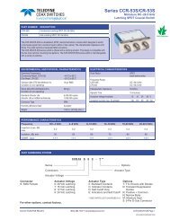
Series HR422/ HRS422<br />
DC up to 1 GHz<br />
Magnetic Latching <strong>Space</strong> Grade DPDT Relay<br />
PART NUMBER<br />
HR422<br />
DESCRIPTION<br />
Magnetic-Latching, DPDT, TO-5 <strong>Space</strong> Grade Relay (HIREL)<br />
HRS422<br />
Magnetic-Latching, DPDT, TO-5 <strong>Space</strong> Grade Relay (HIREL), Surface Mount<br />
J-Leads<br />
<strong>Teledyne</strong> <strong>Relays</strong>’ HR/HRS422 Series relay is a High Reliability Off-The Shelf (COTS) relay suitable for<br />
demanding space flight applications. When purchased in accordance with <strong>Teledyne</strong> <strong>Relays</strong>’ standard<br />
Hi-Rel Acceptance Test Procedure (ATP) the relays will meet the basic requirements of both the NASA<br />
Goddard <strong>Space</strong> Flight Center’s S-311-P-754 Document and the European <strong>Space</strong> Agency’s (ESA) SCC<br />
3601 & 3602 Specifications. The HR/HRS422 Series has become the premier selection for space flight<br />
applications requiring low-level switching to dry circuits up to 1 Amp. <strong>Teledyne</strong> <strong>Relays</strong>’ 50 year history of<br />
supplying relays to the spacecraft manufacturing community has supported 95% of all satellite programs<br />
worldwide. <strong>Relays</strong> may be supplied in accordance with the standard requirements of the Hi-Rel ATP or<br />
as specified by customer s<strong>our</strong>ce control drawings. In addition to enhanced test and inspection at the<br />
relay level the individual piece parts are inspected to higher standards. Relay leads may be supplied in<br />
either gold (Au) or solder dipped finish. A variety of formed lead configurations performed by the factory<br />
are available. All Hi-Rel relays are supplied with full data packages in either hard copy or electronic<br />
format. Customer S<strong>our</strong>ce Inspection (CSI) may be performed during critical manufacturing and test<br />
points.<br />
HR/HRS422 HIREL SERIES OVERVIEW<br />
Design Based on QPL-Approved MIL-PRF-39016 Specification<br />
Proven <strong>Space</strong> Flight Heritage<br />
Meets the general requirements of NASA/GSFC, S311-P-754<br />
Meets the general requirements of ESA/SCC General Specification 3601 & 3602<br />
1x10 -8 Leak Rate<br />
Standard Acceptance Test Procedure (ATP) Meets both ESA and NASA Requirements<br />
MIL-DTL-45204 Gold Plating<br />
ANSI-J-STD-006 Requirements for Electric Grade Solder Alloys and Fluxed and Non-Fluxed Sold Solders for Electronic Soldering Applications<br />
100% Small Particle/ Inspection (Millipore Cleaning)<br />
STANDARD HIREL SCREENING<br />
100% Pre-Cap Inspection (S<strong>our</strong>ce Inspection Available) Particle Impact Noise Detection (PIND)<br />
Room Temperature Electrical Measurements<br />
Internal Moisture<br />
Solderability<br />
Thermal Cycle/Miss Test (5,000 cycles total) + 2,500 at Room Temperature<br />
Leak/Seal Test (1x10 -8 ) cc/sec<br />
Room Temperature Electrical Measurements<br />
External Visual & Mechanical<br />
Radiographic Inspection (X-Ray)<br />
Vibration, Sinusoidal (30 G’s) Percent Defect Allowable, failure rate of lot (less than 10%)<br />
ENVIRONMENTAL AND PHYSICAL CHARACTERISTICS<br />
Form Factor 2 Form C (DPDT) Operating Temperature –65°C to +125°C<br />
Frequency Range DC-3 GHz Vibration (Sinusoidal) 30 g’s 10 to 2500 Hz<br />
Lead Finish Gold Plated or Solder Coated Shock (Specific Pulse)<br />
100 g’s,<br />
6ms half sine<br />
Hermetic Seal 1 x 10 -8 atm-cm 3 /s Weight 0.10 oz. (2.84) max.<br />
© 2013 <strong>Teledyne</strong> Coax Switches (800) 351-7368 • www.teledynerelays.com • +44 (0) 1236 453124 • www.teledyne-europe.com Page 19
Series HR422/ HRS422<br />
DC up to 1 GHz<br />
Magnetic Latching <strong>Space</strong> Grade DPDT Relay<br />
Contact Load and Life Ratings<br />
LOAD LEVEL CONTACT LOAD CONTACT LIFE<br />
Low level/Mechanical<br />
10-50μA at 10-50 mVdc or Peak AC<br />
100,000 cycles rated life<br />
1,000,000 cycles unmonitored<br />
(Mechanical Life)<br />
Intermediate Current 100mA at 28Vdc 50,000 cycles<br />
High Level, Resistive 1.0A at 28Vdc 100,000 cycles<br />
High Level, Inductive 200mA at 28Vdc, with 0.32H inductance 100,000 cycles<br />
High Level, Lamp 100mA at 28Vdc 100,000 cycles<br />
Overload, Resistive 2.0A at 28Vdc 100 cycles<br />
Specifi cations based on relay case being grounded, unless otherwise specifi ed<br />
Static Contact Resistance or Voltage Drop<br />
Maximum Static Contact Resistance or Voltage Drop<br />
Measurement Condition<br />
Low Level Life<br />
Intermediate<br />
Current<br />
High Level Life<br />
Overload<br />
Without attached spacer/<br />
spreader pad<br />
With M4 spacer pad attached<br />
With M or M3 spreader pad<br />
attached<br />
Initial 0.125Ω 0.135Ω 0.150Ω<br />
During test<br />
After 100,000 or<br />
1,000,000 cycle life<br />
33Ω (1.65mVdc monitoring Level)<br />
0.175Ω 0.185Ω 0.200Ω<br />
During test<br />
1Ω (100mVdc monitoring Level)<br />
After 50,000 0.225Ω 0.235Ω 0.250Ω<br />
During life<br />
After 100,000 cycle<br />
life<br />
Voltage drop no more than 5% of open circuit voltage (1.4 Vdc monitoring level)<br />
0.225Ω 0.235Ω 0.250Ω<br />
During test<br />
Not Monitored<br />
After 100 cycle life 0.225Ω 0.235Ω 0.250Ω<br />
General Electrical Specifications<br />
Insulation Resistance<br />
Dielectric Strength<br />
Operate Time<br />
Coil Transient Suppresion<br />
(Vdc)<br />
Block Integrity max. leakage<br />
current<br />
Breakdown Voltage<br />
10,000 MΩ minimum at 500Vdc<br />
1,000MΩ minimum at 500Vdc between coil and case at +125°C<br />
1,000MΩ minimum at 500Vdc after 100 cycle overload<br />
100,000 cycle high life, or 50,000 intermediate current tests<br />
500Vrms ±5% at 50 or 60Hz<br />
375Vrms at 50 or 60Hz after 100 cycle overload, 100,000 cycle high level life, or<br />
50,000 intermediate current tests<br />
2.0 ms maximum with rated coil voltage<br />
1.0 max.<br />
1μA at 50Vdc<br />
100Vdc min. at 10μA<br />
Page 20 SPECIFICATIONS SUBJECT TO CHANGE WITHOUT NOTICE © 2013 <strong>Teledyne</strong> <strong>Relays</strong>
Series HR422/ HRS422<br />
DC up to 1 GHz<br />
Magnetic Latching <strong>Space</strong> Grade DPDT Relay<br />
Coil Data and Operating Characteristics of Basic <strong>Relays</strong> and of <strong>Relays</strong> with Optional Diode for Coil Transient Suppression<br />
Coil Voltage (Vdc) Room Ambient Temperature (+25°C) Over Temperature Range<br />
Rated<br />
Max<br />
Coil<br />
Resistance (Ω) ±10%<br />
Set/reset\<br />
voltage (V d.c.)<br />
max<br />
Pick-Up Voltage (Vdc) max.<br />
5.0 6.0 61 2.8 3.5<br />
6.0 8.0 120 3.5 4.5<br />
9.0 12.0 280 5.3 6.8<br />
12.0 16.0 500 7.0 9.0<br />
18.0 24.0 1130 10.5 13.5<br />
26.5 32.0 2000 14.2 18.0<br />
Coil Data and Operating Characteristics of <strong>Relays</strong> with Optional Diodes for Coil Transient Suppression and Polarity<br />
Reversal Protection<br />
Coil Voltage (Vdc)<br />
Rated<br />
Max<br />
Coil Resistance (Ω)<br />
±10%<br />
Room Ambient Temperature (+25°C)<br />
Max<br />
Coil Circuit Current<br />
(mA 4/)<br />
Min<br />
Set/reset voltage<br />
(V d.c.)<br />
max<br />
Over Temperature<br />
Range<br />
Set/reset voltage<br />
(V d.c.)<br />
max<br />
5.0 6.0 48 104.2 75.8 3.5 4.5<br />
6.0 8.0 97 63.0 46.9 4.1 5.5<br />
9.0 12.0 280 33.7 26.0 6.3 7.8<br />
12.0 16.0 500 25.5 20.0 8.0 10.0<br />
18.0 24.0 1130 17.2 13.7 11.6 14.5<br />
26.5 32.0 2000 14.4 11.6 15.4 19.0<br />
© 2013 <strong>Teledyne</strong> Coax Switches (800) 351-7368 • www.teledynerelays.com • +44 (0) 1236 453124 • www.teledyne-europe.com Page 21
Series HR422K/ HRS422K<br />
DC up to 1 GHz, High Shock<br />
Magnetic Latching <strong>Space</strong> Grade DPDT Relay<br />
PART NUMBER<br />
HR422K<br />
DESCRIPTION<br />
Magnetic-Latching, DPDT, TO-5 <strong>Space</strong> Grade Relay (HIREL), High Shock<br />
HRS422K<br />
Magnetic-Latching, DPDT, TO-5 <strong>Space</strong> Grade Relay (HIREL), High Shock,<br />
Surface Mount J-Leads<br />
<strong>Teledyne</strong> <strong>Relays</strong>’ HR/HRS422K Series relay is a Commercial Off-The Shelf (COTS) relay suitable for<br />
high reliability space flight applications. When purchased in accordance with <strong>Teledyne</strong> <strong>Relays</strong>’ standard<br />
Hi-Rel Acceptance Test Procedure (ATP) the relays will meet the basic requirements of both the NASA<br />
Goddard <strong>Space</strong> Flight Center’s S-311-P-754 Document and the European <strong>Space</strong> Agency’s (ESA) SCC<br />
3601 & 3602 Specifications. The HR/HRS422K Series has become the premier selection for space flight<br />
applications requiring low-level switching to dry circuits up to 1 Amp. <strong>Teledyne</strong> <strong>Relays</strong>’ 50 year history of<br />
supplying relays to the spacecraft manufacturing community has supported 95% of all satellite programs<br />
worldwide. <strong>Relays</strong> may be supplied in accordance with the standard requirements of the Hi-Rel ATP or<br />
as specified by customer s<strong>our</strong>ce control drawings. In addition to enhanced test and inspection at the<br />
relay level the individual piece parts are inspected to higher standards. Relay leads may be supplied in<br />
either gold (Au) or solder dipped finish. A variety of formed lead configurations performed by the factory<br />
are available. All Hi-Rel relays are supplied with full data packages in either hard copy or electronic<br />
format. Customer S<strong>our</strong>ce Inspection (CSI) may be performed during critical manufacturing and test<br />
points.<br />
HR/HRS422K HIREL SERIES OVERVIEW<br />
Design Based on QPL-Approved MIL-PRF-39016 Specification<br />
Proven <strong>Space</strong> Flight Heritage<br />
Meets the general requirements of NASA/GSFC, S311-P-754<br />
Meets the general requirements of ESA/SCC General Specification 3601 & 3602<br />
1x10 -8 Leak Rate<br />
Standard Acceptance Test Procedure (ATP) Meets both ESA and NASA Requirements<br />
MIL-DTL-45204 Gold Plating<br />
ANSI-J-STD-006 Requirements for Electric Grade Solder Alloys and Fluxed and Non-Fluxed Sold Solders for Electronic Soldering Applications<br />
100% Small Particle/ Inspection (Millipore Cleaning)<br />
STANDARD HIREL SCREENING<br />
100% Pre-Cap Inspection (S<strong>our</strong>ce Inspection Available) Particle Impact Noise Detection (PIND)<br />
Room Temperature Electrical Measurements<br />
Internal Moisture<br />
Solderability<br />
Thermal Cycle/Miss Test (5,000 cycles total) + 2,500 at Room Temperature<br />
Leak/Seal Test (1x10 -8 ) cc/sec<br />
Room Temperature Electrical Measurements<br />
External Visual & Mechanical<br />
Radiographic Inspection (X-Ray)<br />
Vibration, Sinusoidal (30 G’s) Percent Defect Allowable, failure rate of lot (less than 10%)<br />
ENVIRONMENTAL AND PHYSICAL CHARACTERISTICS<br />
Form Factor 2 Form C (DPDT) Operating Temperature –65°C to +125°C<br />
Frequency Range DC-3 GHz Vibration (Sinusoidal) 30 g’s 10 to 2500 Hz<br />
Lead Finish Gold Plated or Solder Coated Shock (Specific Pulse)<br />
100 g’s,<br />
6ms half sine<br />
Hermetic Seal 1 x 10 -8 atm-cm 3 /s Weight 0.1 oz. (2.84) max.<br />
Page 22 SPECIFICATIONS SUBJECT TO CHANGE WITHOUT NOTICE © 2013 <strong>Teledyne</strong> <strong>Relays</strong>
Series HR422K/ HRS422K<br />
DC up to 1 GHz, High Shock<br />
Magnetic Latching <strong>Space</strong> Grade DPDT Relay<br />
Contact Load and Life Ratings<br />
LOAD LEVEL CONTACT LOAD CONTACT LIFE<br />
Low level/Mechanical<br />
10-50μA at 10-50 mVdc or Peak AC<br />
100,000 cycles rated life<br />
1,000,000 cycles unmonitored<br />
(Mechanical Life)<br />
Intermediate Current 100mA at 28Vdc 50,000 cycles<br />
High Level, Resistive 1.0A at 28Vdc 100,000 cycles<br />
High Level, Inductive 200mA at 28Vdc, with 0.32H inductance 100,000 cycles<br />
High Level, Lamp 100mA at 28Vdc 100,000 cycles<br />
Overload, Resistive 2.0A at 28Vdc 100 cycles<br />
Specifi cations based on relay case being grounded, unless otherwise specifi ed<br />
Static Contact Resistance or Voltage Drop<br />
Maximum Static Contact Resistance or Voltage Drop<br />
Measurement Condition<br />
Low Level Life<br />
Intermediate<br />
Current<br />
High Level Life<br />
Overload<br />
Without attached spacer/<br />
spreader pad<br />
With M4 spacer pad attached<br />
With M/M3 spreader pad<br />
attached<br />
Initial 0.125Ω 0.135Ω 0.150Ω<br />
During test<br />
After 100,000 or<br />
1,000,000 cycle life<br />
33Ω (1.65mVdc monitoring Level)<br />
0.175Ω 0.185Ω 0.200Ω<br />
During test<br />
1Ω (100mVdc monitoring Level)<br />
After 50,000 0.225Ω 0.235Ω 0.250Ω<br />
During life<br />
After 100,000 cycle<br />
life<br />
Voltage drop no more than 5% of open circuit voltage (1.4 Vdc monitoring level)<br />
0.225Ω 0.235Ω 0.250Ω<br />
During test<br />
Not Monitored<br />
After 100 cycle life 0.225Ω 0.235Ω 0.250Ω<br />
General Electrical Specifications<br />
Insulation Resistance<br />
Dielectric Strength<br />
Operate Time<br />
Coil Transient Suppression<br />
(Vdc)<br />
Block Integrity max. leakage<br />
current<br />
Breakdown Voltage<br />
10,000 MΩ minimum at 500Vdc<br />
1,000MΩ minimum at 500Vdc between coil and case at +125°C<br />
1,000MΩ minimum at 500Vdc after 100 cycle overload<br />
100,000 cycle high life, or 50,000 intermediate current tests<br />
500Vrms ±5% at 50 or 60Hz<br />
375Vrms at 50 or 60Hz after 100 cycle overload, 100,000 cycle high level life, or<br />
50,000 intermediate current tests<br />
2.0 ms maximum with rated coil voltage<br />
1.0 max.<br />
1μA at 50Vdc<br />
100Vdc min. at 10μA<br />
© 2013 <strong>Teledyne</strong> Coax Switches (800) 351-7368 • www.teledynerelays.com • +44 (0) 1236 453124 • www.teledyne-europe.com Page 23
Series HR422K/ HRS422K<br />
DC up to 1 GHz, High Shock<br />
Magnetic Latching <strong>Space</strong> Grade DPDT Relay<br />
Coil Data and Operating Characteristics of Basic <strong>Relays</strong> and of <strong>Relays</strong> with Optional Diode for Coil Transient Suppression<br />
Coil Voltage (Vdc) Room Ambient Temperature (+25°C) Over Temperature Range<br />
Rated Max Coil Resistance (Ω) ±10% Set/reset voltage (V d.c.) max Set/reset voltage (V d.c.) max<br />
5.0 6.0 61 2.8 3.5<br />
6.0 8.0 120 3.5 4.5<br />
9.0 12.0 280 5.3 6.8<br />
12.0 16.0 500 7.0 9.0<br />
18.0 24.0 1130 10.5 13.5<br />
26.5 32.0 2000 14.2 18.0<br />
Page 24 SPECIFICATIONS SUBJECT TO CHANGE WITHOUT NOTICE © 2013 <strong>Teledyne</strong> <strong>Relays</strong>
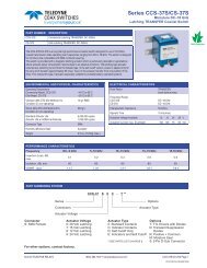
Series HR255/HR257<br />
DC up to 3 GHz<br />
Magnetic Latching <strong>Space</strong> Grade DPDT Relay<br />
PART NUMBER<br />
HR255, HR257<br />
DESCRIPTION<br />
Magnetic-Latching, DPDT, Half-Size Crystal Can, <strong>Space</strong> Grade Relay (HIREL)<br />
<strong>Teledyne</strong> <strong>Relays</strong>’ HR255/257 Series relay is a High Reliability Off-The Shelf (COTS) relay suitable for<br />
demanding space flight applications. When purchased in accordance with <strong>Teledyne</strong> <strong>Relays</strong>’ standard<br />
Hi-Rel Acceptance Test Procedure (ATP) the relays will meet the basic requirements of both the NASA<br />
Goddard <strong>Space</strong> Flight Center’s S-311-P-754 Document and the European <strong>Space</strong> Agency’s (ESA) SCC<br />
3601 & 3602 Specifications. The HR255/HR257 Series has become the premier selection for space flight<br />
applications requiring low-level switching to dry circuits up to 2 Amp. <strong>Teledyne</strong> <strong>Relays</strong>’ 50 year history of<br />
supplying relays to the spacecraft manufacturing community has supported 95% of all satellite programs<br />
worldwide. <strong>Relays</strong> may be supplied in accordance with the standard requirements of the Hi-Rel ATP or<br />
as specified by customer s<strong>our</strong>ce control drawings. In addition to enhanced test and inspection at the<br />
relay level the individual piece parts are inspected to higher standards. Relay leads may be supplied in<br />
either gold (Au) or solder dipped finish. All Hi-Rel relays are supplied with full data packages in either<br />
hard copy or electronic format. Customer S<strong>our</strong>ce Inspection (CSI) may be performed during critical<br />
manufacturing and test points.<br />
HR255/HR257 HIREL SERIES OVERVIEW<br />
Design Based on QPL-Approved MIL-PRF-39016 Specification<br />
Proven <strong>Space</strong> Flight Heritage<br />
Meets the general requirements of NASA/GSFC, S311-P-754<br />
Meets the general requirements of ESA/SCC General Specification 3601 & 3602<br />
1x10 -8 Leak Rate<br />
Standard Acceptance Test Procedure (ATP) Meets both ESA and NASA Requirements<br />
MIL-DTL-45204 Gold Plating<br />
ANSI-J-STD-006 Requirements for Electric Grade Solder Alloys and Fluxed and Non-Fluxed Sold Solders for Electronic Soldering Applications<br />
100% Small Particle/ Inspection (Millipore Cleaning)<br />
STANDARD HIREL SCREENING (SEE DETAILED SUMMARY OF STANDARD SCREENING ON PAGE 4-9)<br />
100% Pre-Cap Inspection (S<strong>our</strong>ce Inspection Available) Particle Impact Noise Detection (PIND)<br />
Room Temperature Electrical Measurements<br />
Internal Moisture<br />
Solderability<br />
Thermal Cycle/Miss Test (5,000 cycles total)<br />
Leak/Seal Test (1x10 -8 )<br />
Room Temperature Electrical Measurements<br />
External Visual & Mechanical<br />
Radiographic Inspection (X-Ray)<br />
Vibration, Sinusoidal (30 G’s) Percent Defect Allowable, failure rate of lot (less than 10%)<br />
ENVIRONMENTAL AND PHYSICAL CHARACTERISTICS<br />
Form Factor 2 Form C (DPDT) Operating Temperature –65°C to +125°C<br />
Frequency Range DC-3 GHz Vibration (Sinusoidal) 30 g’s 10 to 2500 Hz<br />
Lead Finish Gold Plated or Solder Coated Shock (Specific Pulse)<br />
100 g’s,<br />
6ms half sine<br />
Hermetic Seal 1 x 10 -8 atm-cm 3 /s Weight 0.46 oz. (13) max.<br />
© 2013 <strong>Teledyne</strong> Coax Switches (800) 351-7368 • www.teledynerelays.com • +44 (0) 1236 453124 • www.teledyne-europe.com Page 25
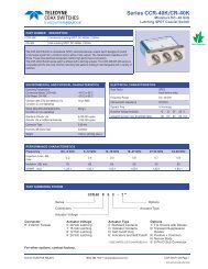
Series HR255/HR257<br />
DC up to 3 GHz<br />
Magnetic Latching <strong>Space</strong> Grade DPDT Relay<br />
MECHANICAL OUTLINE<br />
HR257<br />
B3 A2 A1<br />
X1<br />
Y2<br />
X2<br />
Y1<br />
B1<br />
B2<br />
A3<br />
HR255<br />
B3 A2 A1<br />
X1<br />
Y2<br />
X2<br />
DIMENSIONS ARE IN INCHES, (mm)<br />
B1<br />
Y1<br />
B2<br />
A3<br />
Page 26 SPECIFICATIONS SUBJECT TO CHANGE WITHOUT NOTICE © 2013 <strong>Teledyne</strong> <strong>Relays</strong>
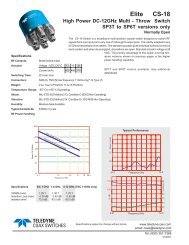
Series HR255/HR257<br />
DC up to 3 GHz<br />
Magnetic Latching <strong>Space</strong> Grade DPDT Relay<br />
TYPICAL POWER PERFORMANCE CURVE<br />
Power Handling vs. Frequency<br />
1000<br />
255/257 RF POWER HANDLING CAPABILITY<br />
RF POWER, Watts<br />
300<br />
200<br />
100<br />
10<br />
Hot Switched<br />
Carry<br />
1<br />
1 10 100 1,000<br />
FREQUENCY, MHz<br />
3,000<br />
Test Notes:<br />
1. Test condition: Ambient temperature and pressure.<br />
2. Hot switched cycle rate: 1/3 Hz.<br />
3. Matched load: 1.2:1 maximum<br />
© 2013 <strong>Teledyne</strong> Coax Switches (800) 351-7368 • www.teledynerelays.com • +44 (0) 1236 453124 • www.teledyne-europe.com Page 27
Series HR255/HR257<br />
DC up to 3 GHz<br />
Magnetic Latching <strong>Space</strong> Grade DPDT Relay<br />
Contact Load and Life Ratings<br />
LOAD LEVEL CONTACT LOAD CONTACT LIFE<br />
Low level/Mechanical<br />
10-50μA at 10-50 mVdc or Peak AC<br />
100,000 cycles rated life<br />
1,000,000 cycles unmonitored<br />
(Mechanical Life)<br />
Intermediate Current 100mA at 28Vdc 50,000 cycles<br />
High Level, Resistive 2.0A at 28Vdc 100,000 cycles<br />
High Level, Inductive 750 mA at 28Vdc, with 0.20H inductance 100,000 cycles<br />
High Level, Lamp 160mA at 28Vdc 100,000 cycles<br />
Overload, Resistive 4.0A at 28Vdc 100 cycles<br />
Specifi cations based on relay case being grounded, unless otherwise specifi ed<br />
Static Contact Resistance or Voltage Drop<br />
Measurement Condition<br />
Maximum Static Contact Resistance or Voltage Drop<br />
Low Level Life<br />
Intermediate<br />
Current<br />
High Level Life<br />
Overload<br />
Initial 0.050Ω<br />
During test<br />
After 100,000 or<br />
1,000,000 cycle life<br />
33Ω (1.65mVdc monitoring Level)<br />
0.150Ω<br />
During test<br />
3Ω (100mVdc monitoring Level)<br />
After 50,000 0.100Ω<br />
During life<br />
After 100,000 cycle<br />
life<br />
Voltage drop no more than 5% of open circuit voltage (1.4 Vdc monitoring level)<br />
0.100Ω.<br />
During test<br />
Not Monitored<br />
After 100 cycle life 0.100Ω<br />
General Electrical Specifications<br />
Insulation Resistance<br />
Dielectric Strength<br />
Operate Time<br />
Bounce Time<br />
1,000 MΩ minimum at 500Vdc<br />
500MΩ minimum at 500Vdc between coil and case at +125°C<br />
500MΩ minimum at 500Vdc after 100 cycle overload<br />
100,000 cycle high life, or 50,000 intermediate current tests<br />
500Vrms ±5% at 50 or 60Hz<br />
375Vrms at 50 or 60Hz after 100 cycle overload, 100,000 cycle high level life, or<br />
50,000 intermediate current tests<br />
3.0 ms maximum with rated coil voltage<br />
4.0 ms maximum with rated coil voltage<br />
Page 28 SPECIFICATIONS SUBJECT TO CHANGE WITHOUT NOTICE © 2013 <strong>Teledyne</strong> <strong>Relays</strong>
Series HR255/HR257<br />
DC up to 3 GHz<br />
Magnetic Latching <strong>Space</strong> Grade DPDT Relay<br />
Coil Data and Operating Characteristics of Basic <strong>Relays</strong><br />
Coil Voltage (Vdc) Room Ambient Temperature (+25°C) Over Temperature Range<br />
Coil Resistance (Ω)<br />
Latch/Reset Voltage (Vdc)<br />
Latch/Reset Voltage (Vdc)<br />
Rated<br />
Max<br />
±10%<br />
Max Min Max Min<br />
5.0 6.7 45 2.7 1.6 3.8 1.0<br />
6.0 8.0 63 3.25 2.0 4.5 1.3<br />
12.0 16.0 254 6.5 4.0 9.0 2.6<br />
26.5 32.0 1000 13.0 8.0 18.0 5.2<br />
48.0 64.0 3800 26.0 16.0 36.0 10.4<br />
COAX Switch Test/Inspection Flow<br />
1<br />
100% Pre-Cap<br />
2<br />
Pre-Cap, S<strong>our</strong>ce<br />
Inspection (If<br />
Required)<br />
3<br />
Small Particle<br />
Inspection/<br />
Millipore Clean<br />
4<br />
Sinusoidal<br />
Vibration<br />
5<br />
P.I.N.D. Test<br />
(When specified)<br />
6<br />
Internal Moisture<br />
7<br />
Temperature<br />
Conditioning and<br />
High and Low<br />
Temperature<br />
Miss Test<br />
8<br />
Room<br />
Temperature<br />
Miss Test<br />
9<br />
Electrical<br />
Measurements<br />
10<br />
Leak Tests<br />
11<br />
Radiographic<br />
Inspection<br />
(X-Ray)<br />
12<br />
External<br />
(Visual<br />
Inspection)<br />
© 2013 <strong>Teledyne</strong> Coax Switches (800) 351-7368 • www.teledynerelays.com • +44 (0) 1236 453124 • www.teledyne-europe.com Page 29
DETAILED SUMMARY OF STANDARD SCREENING<br />
100% Pre-Cap Inspection<br />
100% Small Particle Inspection (Millipore Clean)<br />
Room Temperature Electrical Measurements<br />
Coil Resistance<br />
Coil Current<br />
Insulation Resistance<br />
<strong>Relays</strong> shall be examined to verify worksmanship and cleanliness of<br />
the contact systems and motor mechanisms. Customer service<br />
inspection may be performed.<br />
In process inspection to further evaluate relay cleanliness by quality<br />
control inspectors prior to seal.<br />
Relay coils shall be tested in accordance with MIL-STD-202, method<br />
203. Limit of error of measuring apparatus: ±2.5%<br />
Rated voltage shall be applied to the coil supply terminals, and the coil<br />
circuit current shall be measured using suitable means.<br />
Measurement shall be made at room ambient temperature at rated<br />
voltage for 5 seconds maximum. Limit of error of measuring<br />
apparatus: ±2.5%<br />
The insulation resistance shall be 10,000 MΩ or more, unless<br />
otherwise specified. After the overload, high level life, and intermediate<br />
current tests, the insulation resistance shall be 1,000 MΩ or more.<br />
<strong>Relays</strong> shall withstand the test voltage specified without damage,<br />
and there shall be no leakage current in excess of 100 μA r.m.s. nor<br />
external evidence of damage due to arcing (air discharge), flash over<br />
Dielectric Withstanding Voltage (Atmospheric Pressure) (surface discharge), or insulation breakdown (puncture discharge).<br />
After the overload, high level life, and intermediate current tests, the<br />
dielectric withstanding voltage shall be at least 75 % of the allowable<br />
initial atmospheric value.<br />
Static Contact Resistance The static contact resistance shall not exceed 0.100 Ω.<br />
Operating Characteristics<br />
Operate and Release Time<br />
Dynamic Contact Resistance<br />
Solderability<br />
<strong>Relays</strong> shall be tested in accordance with<br />
MIL-STD-202,method 208.<br />
Seal<br />
Visual Inspection (External)<br />
Pickup voltage as specified<br />
Drop-Out voltage as specified<br />
The operate and release time shall be as specified. For double-throw<br />
contacts, there shall be no closing of open contacts before all closed<br />
contacts have opened. This applies to either state of the relay.<br />
Contact bounce time as specified<br />
Contact stabilization time: The time to reach and maintain a static<br />
contact resistance state shall not exceed 2.0 ms, when specified. After<br />
overload, high level life, and intermediate current tests, contact bounce<br />
time shall be measured in lieu of contact stabilization time.<br />
Any termination that has less than 5 % of the total solder coated area<br />
(except the area within 0.050 in. from the emergence from the seating<br />
plane) dewetted, nonwetted, or with pinholes is acceptable. Other<br />
anomalies shall not be cause for rejection.<br />
When tested as specified in 4.11.5, there shall be no leakage in<br />
excess of 1 × 10⁻⁸ atm-cm3/s of air.<br />
<strong>Relays</strong> shall be uniform in quality, and be free from cracked and<br />
displaced parts, sharp edges, burrs and other defects that will affect<br />
life and serviceability<br />
Page 30 SPECIFICATIONS SUBJECT TO CHANGE WITHOUT NOTICE © 2013 <strong>Teledyne</strong> <strong>Relays</strong>
DETAILED SUMMARY OF STANDARD SCREENING<br />
Sinusoidal Vibration<br />
Random Vibration (If Specified)<br />
Particle Impact Noise Detection (PIND)<br />
Internal Moisture<br />
Thermal Cycle<br />
Miss Test (Run-in)<br />
<strong>Relays</strong> shall be tested in accordance with MIL-STD-202, method 204.<br />
The following details and exceptions shall apply: Mounting method:<br />
Rigidly mounted by normal mounting means. Test condition D, except<br />
vibration level is the lesser of 0.195 inch double amplitude or 30 G<br />
peak, unless otherwise specified (see 3.1) and the frequency range<br />
shall be 10 Hz to 3,000 Hz. Contacts monitored to detect contact<br />
chatter and transfer<br />
<strong>Relays</strong> shall be tested in accordance with MIL-STD-202, method 214.<br />
The following details and exceptions shall apply: Mounting method:<br />
Rigidly mounted by normal mounting means. Test condition: Table I,<br />
test condition G (0.4 G2 /Hz, 23.9 G r.m.s.). Conacts monitored to<br />
detect contact chatter and transfer.<br />
Each relay shall be subjected to a PIND test capable of<br />
detecting the presence of loose particles within the relay enclosure in<br />
accordance with the requirements of <strong>Teledyne</strong> <strong>Relays</strong>’ Procedure<br />
0-40-824, which must be approved by the Orderer. <strong>Relays</strong> so tested<br />
shall exhibit no evidence of loose particle contamination.<br />
<strong>Relays</strong> (coils de-energized) shall be at ambient room temperature<br />
prior to the start of test. The insulation resistance of all contact pins<br />
to case only shall be measured and observed. The relay coil shall be<br />
energized with 140 % of rated voltage for a period of 2½ minutes.<br />
For latching relays, this test shall be repeated for each coil. The<br />
insulation resistance of all contact pins to case only shall be verified<br />
a minimum of once each 30 seconds during this period.<br />
Each relay shall be subjected to 5 cycles of thermal shock in<br />
accordance with MIL-STD-202, Method 107, Test Condition B at the<br />
minimum and maximum rated temperatures (see 3.1). The following<br />
details and exceptions apply: The relay shall be de-energized during the<br />
first f<strong>our</strong> temperature conditioning cycles, and the coil continuity shall<br />
be monitored continuously during this time. Monitoring current shall not<br />
exceed 300 MA. The relay shall be de-energized during low<br />
temperature. Step one of each temperature cycle shall be high<br />
temperature; step 3 of each temperature cycle shall be low<br />
temperature. At the end of each temperature extreme during the fifth<br />
temperature cycle (Steps 1 and 3), each relay shall be tested as<br />
follows: Non-latching relays shall be energized with maximum rated<br />
coil voltage (see 3.1) for one h<strong>our</strong> minimum. At the end of this time and<br />
while still at the high temperature extreme, perform the following electrical<br />
measurements: insulation resistance (at high<br />
temperature only), static contact resistance, operating characteristics,<br />
operate and release time and contact bounce time. Following the<br />
electrical measurements, perform the miss test.<br />
During Step 4 of the fifth cycle, stabilize the relays at room ambient for<br />
a minimum of 1 h<strong>our</strong>, with the coil(s) de-energized.<br />
<strong>Relays</strong> shall be subjected to a 2,500 cycle run-in test at each of the<br />
applicable ambient temperatures. The following details apply: Coil<br />
energization conditions: The coil(s) shall be energized and cycled at<br />
maximum rated voltage (see 3.1). Cycling Rate: 1 to 5 Hz. Contact<br />
loading: <strong>Relays</strong> shall have the contacts loaded as follows: open circuit<br />
load voltage 10 to 50 mV d.c. or peak a.c., load<br />
current 10 to 50 μA Monitoring: The contact voltage drop or resistance<br />
for each pair of mated contacts shall be monitored during 40 %<br />
minimum of each “on” and each “off” period, within the latter 50 % of<br />
each period. The test equipment shall<br />
record all relay failures<br />
© 2013 <strong>Teledyne</strong> Coax Switches (800) 351-7368 • www.teledynerelays.com • +44 (0) 1236 453124 • www.teledyne-europe.com Page 31
DETAILED SUMMARY OF STANDARD SCREENING<br />
Number of misses allowed: None.<br />
Applicable Ambient Temperature:<br />
Miss Test (cont'd)<br />
Ambient High Temperature +125 º C<br />
Ambient Low Temperature - 65 º C<br />
Ambient Room Temperature +25 º C<br />
Each relay shall be examined to determine proper internal construction<br />
Radiographic Inspection (X-Ray)<br />
in accordance with the requirements of <strong>Teledyne</strong> <strong>Relays</strong>’ Procedure<br />
0-40-193, which must be approved by the Orderer.<br />
Percent Defect Allowable Check for failure lot rate (Must be less than 10%)<br />
Page 32 SPECIFICATIONS SUBJECT TO CHANGE WITHOUT NOTICE © 2013 <strong>Teledyne</strong> <strong>Relays</strong>
Lot Acceptance Tests Level 2<br />
Customer has a choice of any combina of the<br />
groups below<br />
Group I Group II Group III<br />
Group IV<br />
Life Test*<br />
Intermediate Curent<br />
Overload<br />
Mechanical Life<br />
Room Temperature<br />
Electrical<br />
Measurements<br />
Room Temperature<br />
Electrical<br />
Measurements<br />
Room Temperature<br />
Electrical<br />
Measurements<br />
Room Temperature<br />
Electrical<br />
Measurements<br />
Tests<br />
Seal Test<br />
External Visual<br />
Inspen<br />
External Visual<br />
Inspen<br />
External Visual<br />
Inspecn<br />
External Visual<br />
Inspecon<br />
Sampling Plan:<br />
1 per load: max # 4<br />
Minimum # of samples: one (1) per load<br />
Maximum # of Samples: f<strong>our</strong> (4) per load<br />
Acceptance Criteria<br />
No Failures Allowed<br />
Legend:<br />
1. Loads oered:<br />
A. dc Reve: 1 Amp, 28 Vdc, 100,000 cycles, 20± 2 cpm, 125°C<br />
B. dc Inducve: 200 MA, 28 Vdc, 100,00 cycles, 10± 1 cpm, 0.32 H inductanca, 125°C<br />
C. Lamp Load: 100 MA, 28 Vdc, 100,000 cycles<br />
D. Low Level Life: 10-50 microamps, 10-50 millivolts, 100,000 cycles (monitored), 125°C<br />
2.Intermediate Current: 100 mA, 28 Vdc, 50,000 cycles, 10± 1 cpm, , 125°C<br />
3. Overload: 2 Amp, 28 Vdc, 100 cycles, 20± 2 cpm, 125°C<br />
4. Mechanical life: 10-50 microamps, 10-50 millivolts, 1,000,000 cycles (unmonitored), room ambient temperature<br />
© 2013 <strong>Teledyne</strong> Coax Switches (800) 351-7368 • www.teledynerelays.com • +44 (0) 1236 453124 • www.teledyne-europe.com Page 33
Series H-33S<br />
DC up to 26.5 GHz<br />
Latching SPDT <strong>Space</strong> Grade Coaxial Switch<br />
COAX SWITCHES<br />
PART NUMBER<br />
H-33S<br />
DESCRIPTION<br />
<strong>Space</strong> Grade Latching SPDT, DC up to 26.5 GHz<br />
<strong>Teledyne</strong> Coax Switches’ “H-33S Series” RF Coaxial Switch is a High Reliability Off-The-Shelf product<br />
suitable for demanding space flight applications. When purchased in accordance with <strong>Teledyne</strong> Coax<br />
Switches’ standard Hi-Rel Acceptance Test Procedure (ATP), Document No. 0-43-058, the switches will meet<br />
the basic requirements for space flight applications. The “H-33S Series” has become the premier selection for<br />
space flight applications requiring RF switching capability. <strong>Teledyne</strong> <strong>Relays</strong>’ 50 year history of supplying high<br />
reliability products to the space craft manufacturing community has supported 95% of all satellite programs<br />
worldwide. The RF Coax Switches may be supplied in accordance with the standard requirements of the<br />
Hi-Rel ATP or as specified by customer s<strong>our</strong>ce control drawings. In addition to enhanced test and inspection<br />
at the relay level the individual piece parts are inspected to higher standards. The switches may be supplied<br />
with standard SMA connectors or as specified by customer requirements. All Hi-Rel RF Coaxial Switches are<br />
supplied with full data packages in either hard copy or electronic format. Customer S<strong>our</strong>ce Inspection (CSI)<br />
may be performed during critical manufacturing and test points. Test Readiness Review (TRR) and Document<br />
Review Board (DRB) meeting will be supported as required and Qualification Test Programs and Procedures<br />
can be customized as necessary.<br />
H-33S HIREL SERIES OVERVIEW<br />
Design Based on <strong>Teledyne</strong>’s High Reliability Off-The-Shelf <strong>Space</strong> program<br />
Proven <strong>Space</strong> Flight Heritage<br />
Fully Defined Pre-Seal Internal Screening Plan<br />
Fully Defined Post-Seal Standard Acceptance Test Plan and Procedure (ATP)<br />
ANSI-J-STD-006 Requirements for Electric Grade Solder Alloys and Fluxed and Non-Fluxed Solid Solders for Electronic Soldering Applications<br />
STANDARD HIREL SCREENING<br />
Pre-Seal - Standard Internal Screening Plan<br />
Operational Test at Temperature<br />
Thermal Shock<br />
Physical and Mechanical Inspection<br />
Initial Functional<br />
QA/CSI Sign-off<br />
Run-In at Room Ambient<br />
Final Functional<br />
Vibration<br />
ENVIRONMENTAL AND PHYSICAL CHARACTERISTICS<br />
Operating Temperature<br />
–55°C to +85°C<br />
Vibration (MIL-STD-202 Method 214,<br />
10 g’s RMS<br />
Condition D, non-operating)<br />
Shock (MIL-STD-202 Method 213,<br />
500 g’s<br />
Condition D, non-operating)<br />
Finish<br />
Electroless Nickel Plate<br />
Life Cycle, minimum<br />
100,000 cycles<br />
Connector Type<br />
SMA<br />
Weight<br />
2.12 oz. (60g) (max.)<br />
ELECTRICAL CHARACTERISTICS<br />
Form Factor<br />
Frequency Range<br />
RF Leakage<br />
Characteristic Impedance<br />
Operate Time<br />
Release Time<br />
Actuation Voltage Available<br />
Actuation Current, max. @ ambient<br />
SPDT,<br />
break before make<br />
L, S, C, X, KU, K<br />
-95 dBc @ 300 MHz<br />
50 Ohms<br />
10 ms (max.)<br />
10 ms (max.)<br />
28 V<br />
90 mA<br />
PERFORMANCE CHARACTERISTICS<br />
Frequency Option F2 (L-BAND) F4 (S-BAND) F8 (C-BAND) F12 (X-BAND) F18 (KU-BAND) F26 (K-BAND)<br />
DC–2 GHz 2–4 GHz 4–8 GHz 8–12 GHz 12-18 GHz 18-26 GHz<br />
Insertion Loss, dB,<br />
max.<br />
0.15 -0.25 0.35 0.3 0.4 0.65<br />
Isolation, dB, min. 80 70 70 70 60 55<br />
VSWR , max. 1.5:1 1.25:1 1.30:1 1.35:1 1.40:1 1.65:1<br />
Page 34 SPECIFICATIONS SUBJECT TO CHANGE WITHOUT NOTICE © 2013 <strong>Teledyne</strong> <strong>Relays</strong>
COAX SWITCHES<br />
Series H-33S<br />
DC up to 26.5 GHz<br />
Latching SPDT <strong>Space</strong> Grade Coaxial Switch<br />
PART NUMBER<br />
H-33S6C-F2<br />
H-33S6C-F4<br />
H-33S6C-F8<br />
H-33S6C-F12<br />
H-33S6C-F18<br />
H-33S6C-F26<br />
DEFAULT CONFIGURATION<br />
SMA Female Connections<br />
Transient Suppression<br />
9-PIN D-Sub Connector<br />
Indicator Contacts<br />
Venting Screen<br />
MECHANICAL OUTLINE<br />
TELEDYNE COAX<br />
SWITCHES<br />
P/N: _____________<br />
VOLTAGE: _____ VDC<br />
D/C: ____________<br />
M/O: ___________<br />
MADE IN _______<br />
© 2013 <strong>Teledyne</strong> Coax Switches (800) 351-7368 • www.teledynerelays.com • +44 (0) 1236 453124 • www.teledyne-europe.com Page 35
Series H-32N<br />
DC up to 12 GHz<br />
Latching SPDT <strong>Space</strong> Grade Coaxial Switch<br />
COAX SWITCHES<br />
PART NUMBER<br />
H-32N<br />
DESCRIPTION<br />
<strong>Space</strong> Grade Latching SPDT, DC up to 12GHz<br />
<strong>Teledyne</strong> Coax Switches’ “H-32N Series” RF Coaxial Switch is a High Reliability Off-The-Shelf product<br />
suitable for demanding space flight applications. When purchased in accordance with <strong>Teledyne</strong> Coax<br />
Switches’ standard Hi-Rel Acceptance Test Procedure (ATP), Document No. 0-43-058, the switches will meet<br />
the basic requirements for space flight applications. The “H-32N Series” has become the premier selection for<br />
space flight applications requiring RF switching capability. <strong>Teledyne</strong> <strong>Relays</strong>’ 50 year history of supplying high<br />
reliability products to the space craft manufacturing community has supported 95% of all satellite programs<br />
worldwide. The RF Coax Switches may be supplied in accordance with the standard requirements of the<br />
Hi-Rel ATP or as specified by customer s<strong>our</strong>ce control drawings. In addition to enhanced test and inspection<br />
at the relay level the individual piece parts are inspected to higher standards. The switches may be supplied<br />
with standard Type N connector or as specified by customer requirements. All Hi-Rel RF Coaxial Switches are<br />
supplied with full data packages in either hard copy or electronic format. Customer S<strong>our</strong>ce Inspection (CSI)<br />
may be performed during critical manufacturing and test points. Test Readiness Review (TRR) and Document<br />
Review Board (DRB) meeting will be supported as required and Qualification Test Programs and Procedures<br />
can be customized as necessary.<br />
H-32N HIREL SERIES OVERVIEW<br />
Design Based on <strong>Teledyne</strong>’s High Reliability Off-The-Shelf <strong>Space</strong> program<br />
Proven <strong>Space</strong> Flight Heritage<br />
Fully Defined Pre-Seal Internal Screening Plan<br />
Fully Defined Post-Seal Standard Acceptance Test Plan and Procedure (ATP)<br />
ANSI-J-STD-006 Requirements for Electric Grade Solder Alloys and Fluxed and Non-Fluxed Solid Solders for Electronic Soldering Applications<br />
STANDARD HIREL SCREENING<br />
Pre-Seal - Standard Internal Screening Plan<br />
Operational Test at Temperature<br />
Thermal Shock<br />
Physical and Mechanical Inspection<br />
Initial Functional<br />
QA/CSI Sign-off<br />
Run-In at Room Ambient<br />
Final Functional<br />
Vibration<br />
ENVIRONMENTAL AND PHYSICAL CHARACTERISTICS<br />
Operating Temperature<br />
–55°C to +85°C<br />
Vibration (MIL-STD-202 Method 214,<br />
10 g’s RMS<br />
Condition D, non-operating)<br />
Shock (MIL-STD-202 Method 213,<br />
500 g’s<br />
Condition D, non-operating)<br />
Finish<br />
Electroless Nickel Plate<br />
Life Cycle, minimum<br />
100,000 cycles<br />
Connector Type<br />
Type N<br />
Weight<br />
7.05 oz. (200g) (max.)<br />
ELECTRICAL CHARACTERISTICS<br />
Form Factor<br />
Frequency Range<br />
RF Leakage<br />
Characteristic Impedance<br />
Operate Time<br />
Release Time<br />
Actuation Voltage Available<br />
Actuation Current, max. @ ambient<br />
SPDT,<br />
break before make<br />
L, S, C, X<br />
-95 dBc, 10dBm, @300 MHz<br />
50 Ohms<br />
10 ms (max.)<br />
10 ms (max.)<br />
28 V<br />
90 mA<br />
PERFORMANCE CHARACTERISTICS<br />
Frequency Option F2 (L-BAND)<br />
DC–2 GHz<br />
F4 (S-BAND)<br />
2–4 GHz<br />
F8 (C-BAND)<br />
4–8 GHz<br />
F12 (X-BAND)<br />
8–12 GHz<br />
Insertion Loss, dB,<br />
max.<br />
0.2 0.3 0.4 0.55<br />
Isolation, dB, min. 70 70 70 60<br />
VSWR , max. 1.2:1 1.3:1 1.3:1 1.6:1<br />
Page 36 SPECIFICATIONS SUBJECT TO CHANGE WITHOUT NOTICE © 2013 <strong>Teledyne</strong> <strong>Relays</strong>
COAX SWITCHES<br />
Series H-32N<br />
DC up to 12 GHz<br />
Latching SPDT <strong>Space</strong> Grade Coaxial Switch<br />
PART NUMBER<br />
DEFAULT CONFIGURATION<br />
H-32N6C-F2 Type N Female Connections<br />
H-32N6C-F4<br />
H-32N6C-F8<br />
H-32N6C-F12<br />
H-32N6C-F18<br />
Transient Suppression<br />
9-PIN D-Sub Connector<br />
Indicator Contacts<br />
Venting Screen<br />
MECHANICAL OUTLINE<br />
© 2013 <strong>Teledyne</strong> Coax Switches (800) 351-7368 • www.teledynerelays.com • +44 (0) 1236 453124 • www.teledyne-europe.com Page 37
Series H-37S<br />
DC up to 18 GHz<br />
Latching Transfer <strong>Space</strong> Grade Coaxial Switch<br />
COAX SWITCHES<br />
PART NUMBER<br />
H-37S<br />
DESCRIPTION<br />
<strong>Space</strong> Grade Latching Transfer, DC up to 18GHz<br />
<strong>Teledyne</strong> Coax Switches’ “H-37S Series” RF Coaxial Switch is a High Reliability Off-The-Shelf product<br />
suitable for demanding space flight applications. When purchased in accordance with <strong>Teledyne</strong> Coax<br />
Switches’ standard Hi-Rel Acceptance Test Procedure (ATP), Document No. 0-43-058, the switches will meet<br />
the basic requirements for space flight applications. The “H-37S Series” has become the premier selection for<br />
space flight applications requiring RF switching capability. <strong>Teledyne</strong> <strong>Relays</strong>’ 50 year history of supplying high<br />
reliability products to the space craft manufacturing community has supported 95% of all satellite programs<br />
worldwide. The RF Coax Switches may be supplied in accordance with the standard requirements of the<br />
Hi-Rel ATP or as specified by customer s<strong>our</strong>ce control drawings. In addition to enhanced test and inspection<br />
at the relay level the individual piece parts are inspected to higher standards. The switches may be supplied<br />
with standard SMA connectors or as specified by customer requirements. All Hi-Rel RF Coaxial Switches are<br />
supplied with full data packages in either hard copy or electronic format. Customer S<strong>our</strong>ce Inspection (CSI)<br />
may be performed during critical manufacturing and test points. Test Readiness Review (TRR) and Document<br />
Review Board (DRB) meeting will be supported as required and Qualification Test Programs and Procedures<br />
can be customized as necessary.<br />
H-37S HIREL SERIES OVERVIEW<br />
Design Based on <strong>Teledyne</strong>’s High Reliability Off-The-Shelf program<br />
Proven <strong>Space</strong> Flight Heritage<br />
Fully Defined Pre-Seal Internal Screening Plan<br />
Fully Defined Post-Seal Standard Acceptance Test Plan and Procedure (ATP)<br />
ANSI-J-STD-006 Requirements for Electric Grade Solder Alloys and Fluxed and Non-Fluxed Solid Solders for Electronic Soldering Applications<br />
STANDARD HIREL SCREENING<br />
Pre-Seal - Standard Internal Screening Plan<br />
Operational Test at Temperature<br />
Thermal Shock<br />
Physical and Mechanical Inspection<br />
Initial Functional<br />
QA/CSI Sign-off<br />
Run-In at Room Ambient<br />
Final Functional<br />
Vibration<br />
ENVIRONMENTAL AND PHYSICAL CHARACTERISTICS<br />
Operating Temperature<br />
–55°C to +85°C<br />
Vibration (MIL-STD-202 Method 214,<br />
10 g’s RMS<br />
Condition D, non-operating)<br />
Shock (MIL-STD-202 Method 213,<br />
500 g’s<br />
Condition D, non-operating)<br />
Finish<br />
Electroless Nickel Plate<br />
Life Cycle, minimum<br />
100,000 cycles<br />
Connector Type<br />
SMA<br />
Weight<br />
4.5 oz. (127.57g) (max.)<br />
ELECTRICAL CHARACTERISTICS<br />
Form Factor<br />
Frequency Range<br />
RF Leakage<br />
Characteristic Impedance<br />
Operate Time<br />
Release Time<br />
Actuation Voltage Available<br />
Actuation Current, max. @ ambient<br />
Transfer,<br />
break before make<br />
L, S, C, X, KU<br />
-70 dBc @ 10 dBm<br />
50 Ohms<br />
10 ms (max.)<br />
10 ms (max.)<br />
28 V<br />
90 mA<br />
PERFORMANCE CHARACTERISTICS<br />
Frequency Option F2 (L-BAND)<br />
DC–2 GHz<br />
F4 (S-BAND)<br />
2–4 GHz<br />
F8 (C-BAND)<br />
4–8 GHz<br />
F12 (X-BAND)<br />
8–12 GHz<br />
F18 (KU-BAND)<br />
12-18 GHz<br />
Insertion Loss, dB,<br />
max.<br />
0.15 0.25 0.35 0.5 0.65<br />
Isolation, dB, min. 80 70 70 70 60<br />
VSWR , max. 1.15:1 1.3:1 1.35:1 1.4:1 1.6:1<br />
Page 38 SPECIFICATIONS SUBJECT TO CHANGE WITHOUT NOTICE © 2013 <strong>Teledyne</strong> <strong>Relays</strong>
COAX SWITCHES<br />
Series H-37S<br />
DC up to 18 GHz<br />
Latching Transfer <strong>Space</strong> Grade Coaxial Switch<br />
PART NUMBER<br />
DEFAULT CONFIGURATION<br />
H-37S6C-F2 SMA Female Connections<br />
H-37S6C-F4<br />
H-37S6C-F8<br />
H-37S6C-F12<br />
H-37S6C-F18<br />
Transient Suppression<br />
9-PIN D-Sub Connector<br />
Indicator Contacts<br />
Venting Screen<br />
MECHANICAL OUTLINE<br />
© 2013 <strong>Teledyne</strong> Coax Switches (800) 351-7368 • www.teledynerelays.com • +44 (0) 1236 453124 • www.teledyne-europe.com Page 39
Series H-47N<br />
DC up to 12 GHz<br />
Latching Transfer <strong>Space</strong> Grade Coaxial Switch<br />
COAX SWITCHES<br />
PART NUMBER<br />
H-47N<br />
DESCRIPTION<br />
<strong>Space</strong> Grade Latching Transfer, DC up to 12GHz<br />
<strong>Teledyne</strong> Coax Switches’ “H-47N Series” RF Coaxial Switch is a High Reliability Off-The-Shelf product<br />
suitable for demanding space flight applications. When purchased in accordance with <strong>Teledyne</strong> Coax<br />
Switches’ standard Hi-Rel Acceptance Test Procedure (ATP), Document No. 0-43-058, the switches will meet<br />
the basic requirements for space flight applications. The “H-47N Series” has become the premier selection for<br />
space flight applications requiring RF switching capability. <strong>Teledyne</strong> <strong>Relays</strong>’ 50 year history of supplying high<br />
reliability products to the space craft manufacturing community has supported 95% of all satellite programs<br />
worldwide. The RF Coax Switches may be supplied in accordance with the standard requirements of the<br />
Hi-Rel ATP or as specified by customer s<strong>our</strong>ce control drawings. In addition to enhanced test and inspection<br />
at the relay level the individual piece parts are inspected to higher standards. The switches may be supplied<br />
with standard Type N connector or as specified by customer requirements. All Hi-Rel RF Coaxial Switches are<br />
supplied with full data packages in either hard copy or electronic format. Customer S<strong>our</strong>ce Inspection (CSI)<br />
may be performed during critical manufacturing and test points. Test Readiness Review (TRR) and Document<br />
Review Board (DRB) meeting will be supported as required and Qualification Test Programs and Procedures<br />
can be customized as necessary.<br />
H-47N HIREL SERIES OVERVIEW<br />
Design Based on <strong>Teledyne</strong>’s High Reliability Off-The-Shelf <strong>Space</strong> program<br />
Proven <strong>Space</strong> Flight Heritage<br />
Fully Defined Pre-Seal Internal Screening Plan<br />
Fully Defined Post-Seal Standard Acceptance Test Plan and Procedure (ATP)<br />
ANSI-J-STD-006 Requirements for Electric Grade Solder Alloys and Fluxed and Non-Fluxed Solid Solders for Electronic Soldering Applications<br />
STANDARD HIREL SCREENING<br />
Pre-Seal - Standard Internal Screening Plan<br />
Operational Test at Temperature<br />
Thermal Shock<br />
Physical and Mechanical Inspection<br />
Initial Functional<br />
QA/CSI Sign-off<br />
Run-In at Room Ambient<br />
Final Functional<br />
Vibration<br />
ENVIRONMENTAL AND PHYSICAL CHARACTERISTICS<br />
Operating Temperature<br />
–55°C to +85°C<br />
Vibration (MIL-STD-202 Method 214,<br />
10 g’s RMS<br />
Condition D, non-operating)<br />
Shock (MIL-STD-202 Method 213,<br />
500 g’s<br />
Condition D, non-operating)<br />
Finish<br />
Electroless Nickel Plate<br />
Life Cycle, minimum<br />
100,000 cycles<br />
Connector Type<br />
Type N<br />
Weight<br />
6.5 oz. (184.27g) (max.)<br />
ELECTRICAL CHARACTERISTICS<br />
Form Factor<br />
Frequency Range<br />
Characteristic Impedance<br />
RF Leakage<br />
Operate Time<br />
Release Time<br />
Actuation Voltage Available<br />
Actuation Current, max. @ ambient<br />
Transfer,<br />
break before make<br />
L, S, C, X<br />
50 Ohms<br />
-70 dBc @ 4GHz<br />
10 ms (max.)<br />
10 ms (max.)<br />
28 V<br />
90 mA<br />
PERFORMANCE CHARACTERISTICS<br />
Frequency Option F2 (L-BAND)<br />
DC–2 GHz<br />
F4 (S-BAND)<br />
2–4 GHz<br />
F8 (C-BAND)<br />
4–8 GHz<br />
F12 (X-BAND)<br />
8–12 GHz<br />
Insertion Loss, dB,<br />
max.<br />
0.2 0.3 0.4 0.6<br />
Isolation, dB, min. 70 70 60 60<br />
VSWR , max. 1.3:1 1.3:1 1.4:1 1.65:1<br />
Page 40 SPECIFICATIONS SUBJECT TO CHANGE WITHOUT NOTICE © 2013 <strong>Teledyne</strong> <strong>Relays</strong>
COAX SWITCHES<br />
Series H-47N<br />
DC up to 12 GHz<br />
Latching Transfer <strong>Space</strong> Grade Coaxial Switch<br />
PART NUMBER<br />
H-47N6C-F2<br />
H-47N6C-F4<br />
H-47N6C-F8<br />
H-47N6C-F12<br />
DEFAULT CONFIGURATION<br />
N Female Connections<br />
Transient Suppression<br />
9-PIN D-Sub Connector<br />
Indicator Contacts<br />
Venting Screen<br />
MECHANICAL OUTLINE<br />
© 2013 <strong>Teledyne</strong> Coax Switches (800) 351-7368 • www.teledynerelays.com • +44 (0) 1236 453124 • www.teledyne-europe.com Page 41
Series H-28S<br />
T-Switch DC-22 GHz<br />
Latching Coaxial Switch<br />
COAX SWITCHES<br />
PART NUMBER DESCRIPTION<br />
H-28 Latching T-Switch<br />
The H-28 Series T-Switch is a latching random mode switch. It is a f<strong>our</strong>-port device that features SMA<br />
connector interfaces and is capable of switching broadband RF signals from DC-22 GHz from multiple<br />
input s<strong>our</strong>ces to multiple output devices.<br />
The switch is designed with a characteristic impedance of 50 Ohms. Its magnetic latching drive mechanism,<br />
high reliability RF system, small size and light weight characteristics make this switch suitable for space<br />
and other Hi-Rel applications.<br />
H-28 HIREL SERIES OVERVIEW<br />
Design Based on <strong>Teledyne</strong>’s High Reliability Off-The-Shelf <strong>Space</strong> program<br />
Proven <strong>Space</strong> Flight Heritage<br />
Fully Defined Pre-Seal Internal Screening Plan<br />
Fully Defined Post-Seal Standard Acceptance Test Plan and Procedure (ATP)<br />
ANSI-J-STD-006 Requirements for Electric Grade Solder Alloys and Fluxed and Non-Fluxed Sold Solders for Electronic Soldering Applications<br />
STANDARD HIREL SCREENING<br />
Pre-Seal - Standard Internal Screening Plan<br />
Thermal Shock<br />
Initial Functional<br />
Run-In at Room Ambient<br />
Vibration<br />
Operational Test at Temperature<br />
Physical and Mechanical Inspection<br />
QA/CSI Sign-off<br />
Final Functional<br />
ENVIRONMENTAL AND PHYSICAL CHARACTERISTICS<br />
Operating Temperature:<br />
–55°C to +85°C<br />
Sine Vibration (Non-operating)<br />
20 G peak<br />
Random Vibration (Non-operating)<br />
21.5 Grms<br />
Shock (Non-operating)<br />
800G / 300 μs<br />
(1/2 Sine Pulses)<br />
Typical Contact Life<br />
1,000,000 cycles<br />
Connector Type<br />
SMA<br />
Weight<br />
4.10 oz. (116 g) max.<br />
ELECTRICAL CHARACTERISTICS<br />
Form Factor<br />
Break before make<br />
Frequency Range<br />
DC–22 GHz<br />
Characteristic Impedance<br />
50 Ohms<br />
Switching Time (Set)<br />
20 ms max.<br />
Switching Time (Reset)<br />
10 ms max.<br />
Coil Resistance<br />
265 Ohms nom.<br />
RF Contact Resistance<br />
250 mOhms max.<br />
Indicator Contact Resistance<br />
500 mOhms max.<br />
Insulation Resistance<br />
100 MOhms min.<br />
Actuation Voltage<br />
28Vdc nom., 32Vdc max.<br />
Actuation Current (Per Coil) 135 mA max.@ 28Vdc and 20°C<br />
PERFORMANCE CHARACTERISTICS (SEE PAGES: 4-6)<br />
Parameter<br />
F2 (L-BAND)<br />
DC–2 GHz<br />
F4 (S-BAND)<br />
2–4 GHz<br />
F8 (C-BAND)<br />
4–8 GHz<br />
F12 (X-BAND)<br />
8–12 GHz<br />
F18 (KU-BAND)<br />
12-18 GHz<br />
F22 (K-BAND)<br />
18-22 GHz<br />
Insertion Loss, dB (Max.) 0.12 0.15 0.3 0.35 0.55 0.65<br />
VSWR (Max.) 1.15:1 1.2:1 1.35:1 1.4:1 1.6:1 1.65:1<br />
Isolation, dB (Min.) 70 70 60 60 60 60<br />
Page 42 SPECIFICATIONS SUBJECT TO CHANGE WITHOUT NOTICE © 2013 <strong>Teledyne</strong> <strong>Relays</strong>
COAX SWITCHES<br />
Series H-28S<br />
T-Switch DC-22 GHz<br />
Latching Coaxial Switch<br />
PART NUMBER<br />
DEFAULT CONFIGURATION<br />
H-28S6C-F2 SMA Female Connections<br />
H-28S6C-F4<br />
H-28S6C-F8<br />
H-28S6C-F12<br />
H-28S6C-F18<br />
H-28S6C-F22<br />
Transient Suppresion<br />
9-PIN D-Sub Connector<br />
Indicator Contacts<br />
Venting Screen<br />
SCHEMATIC DIAGRAM<br />
SCHEMATIC (SHOWN IN POS 1)<br />
INDICATOR TRUTH TABLE Failsafe<br />
H-28S6C-TBD<br />
Postion<br />
Coil Voltage Terminals<br />
1 2 3 4 5 6 7<br />
1 SET + - +<br />
RF Paths<br />
J1 - J3<br />
J2 - J4<br />
Indicator<br />
8 - 11<br />
1 RESET - + + Open Open<br />
2 SET + - +<br />
J1 - J2<br />
J3 - J4<br />
9 - 11<br />
2 RESET - + + Open Open<br />
3 SET + - +<br />
J1 - J4<br />
J2 - J3<br />
10 - 11<br />
3 RESET - + + Open Open<br />
Pin 7 is for Coil Transient Suppression Only<br />
© 2013 <strong>Teledyne</strong> Coax Switches (800) 351-7368 • www.teledynerelays.com • +44 (0) 1236 453124 • www.teledyne-europe.com Page 43
Series H-28<br />
T-Switch DC-22 GHz<br />
Latching Coaxial Switch<br />
COAX SWITCHES<br />
MECHANICAL OUTLINE<br />
Page 44 SPECIFICATIONS SUBJECT TO CHANGE WITHOUT NOTICE © 2013 <strong>Teledyne</strong> <strong>Relays</strong>
COAX SWITCHES<br />
Series H-28<br />
T-Switch DC-22 GHz<br />
Latching Coaxial Switch<br />
TYPICAL NARROWBAND RF INSERTION LOSS PERFORMANCE CURVES<br />
Insertion Loss ( DC-22 GHz )<br />
0.0<br />
-0.1<br />
Insertion Loss (dB)<br />
-0.2<br />
-0.3<br />
-0.4<br />
-0.5<br />
-0.6<br />
-0.7<br />
-0.8<br />
-0.9<br />
-1.0<br />
0 5 10 15 20<br />
Frequency (GHz)<br />
COMMON (J4) PORT TO ANY PORT<br />
Insertion Loss ( DC-22 GHz )<br />
0.0<br />
Insertion Loss (dB)<br />
-0.2<br />
-0.4<br />
-0.6<br />
-0.8<br />
-1.0<br />
-1.2<br />
0 5 10 15 20<br />
Frequency (GHz)<br />
RF NOTES<br />
PORT TO PORT<br />
© 2013 <strong>Teledyne</strong> Coax Switches (800) 351-7368 • www.teledynerelays.com • +44 (0) 1236 453124 • www.teledyne-europe.com Page 45
Series H-28<br />
T-Switch DC-22 GHz<br />
Latching Coaxial Switch<br />
COAX SWITCHES<br />
TYPICAL NARROWBAND RF ISOLATION PERFORMANCE CURVES<br />
0<br />
Isolation ( DC-22 GHz )<br />
-20<br />
Isolation (dB)<br />
-40<br />
-60<br />
-80<br />
-100<br />
-120<br />
-140<br />
0 5 10 15 20<br />
Frequency (GHz)<br />
COMMON (J4) PORT TO ANY PORT<br />
0<br />
Isolation ( DC-22 GHz )<br />
-20<br />
Isolation (dB)<br />
-40<br />
-60<br />
-80<br />
-100<br />
-120<br />
-140<br />
0 5 10 15 20<br />
Frequency (GHz)<br />
RF NOTES<br />
PORT TO PORT<br />
Page 46 SPECIFICATIONS SUBJECT TO CHANGE WITHOUT NOTICE © 2013 <strong>Teledyne</strong> <strong>Relays</strong>
COAX SWITCHES<br />
Series H-28<br />
T-Switch DC-22 GHz<br />
Latching Coaxial Switch<br />
TYPICAL NARROWBAND RF VSWR PERFORMANCE CURVES<br />
2.0<br />
VSWR ( DC-22 GHz )<br />
VSWR<br />
1.9<br />
1.8<br />
1.7<br />
1.6<br />
1.5<br />
1.4<br />
1.3<br />
1.2<br />
1.1<br />
1.0<br />
0 5 10 15 20<br />
Frequency (GHz)<br />
COMMON (J4) PORT TO ANY PORT<br />
2.0<br />
VSWR ( DC-22 GHz )<br />
VSWR<br />
1.9<br />
1.8<br />
1.7<br />
1.6<br />
1.5<br />
1.4<br />
1.3<br />
1.2<br />
1.1<br />
1.0<br />
0 5 10 15 20<br />
Frequency (GHz)<br />
RF NOTES<br />
PORT TO PORT<br />
© 2013 <strong>Teledyne</strong> Coax Switches (800) 351-7368 • www.teledynerelays.com • +44 (0) 1236 453124 • www.teledyne-europe.com Page 47
COAX SWITCHES<br />
ATP COAX Test Flow<br />
Standard Internal<br />
Screening Test Plan<br />
Standard Acceptance<br />
Test Plan<br />
Group B Test<br />
Functional<br />
Electrical<br />
Functional<br />
Electrical<br />
Functional<br />
Electrical<br />
Thermal Shock<br />
Random<br />
Vibration<br />
Shine Vibration<br />
Run-in @ Hot<br />
Thermal Shock<br />
Random<br />
Vibration<br />
Run-in @ Cold<br />
Final Electrical<br />
Shock<br />
Electrical @ Hot<br />
External Visual<br />
+ Mechanical<br />
Thermal<br />
Vacuum<br />
Electrical @<br />
Cold<br />
Final Electrical<br />
External Visual<br />
+Mechanical<br />
Page 48 SPECIFICATIONS SUBJECT TO CHANGE WITHOUT NOTICE © 2013 <strong>Teledyne</strong> <strong>Relays</strong>
COAX SWITCHES<br />
DETAILED SUMMARY OF STANDARD SCREENING<br />
Pre-Seal - Inspection 100% Visual Inspection<br />
VSWR<br />
Insertion Loss<br />
Electrical Test at Room Ambient<br />
Isolation, Minimum<br />
Operating Voltage<br />
Switching Time<br />
Coil Resistance<br />
Thermal Shock 5 cycles 1-h<strong>our</strong> dwell at each temperature -55°C and +85°C<br />
Run In at Room Temperature Extremes<br />
Temperature, per <strong>Teledyne</strong> standard or customer’s requirement<br />
500 actuations at each temperature extreme 250 actuation,<br />
non-monitor 250 actuation, contact-resistance monitor<br />
Electrical Test at Temperatures<br />
VSWR<br />
Insertion Loss<br />
Isolation<br />
Minimum Operation Voltage<br />
Switching Time<br />
Coil Resistance<br />
Contact Resistance<br />
Vibration, Random<br />
Post-vibration Functional<br />
Final Functional at Room Ambient<br />
Physical and Mechanical Inspection<br />
QA/CSI Sign-off<br />
In addition to the standard environmental tests,<br />
upon customer request, the following<br />
tests may be performed at any time during<br />
acceptance test:<br />
VSWR<br />
Insertion Loss<br />
Minimum Operating Voltage<br />
Minimum Switching Time<br />
RF Contact Resistance<br />
Indicator Contact Resistance (if applicable)<br />
VSWR<br />
Insertion Loss<br />
Isolation<br />
Minimum Operating Voltage<br />
Minimum Switching Time<br />
RF Contact Resistance<br />
Indicator Contact Resistance<br />
Coil Resistance<br />
Mechanical Shock<br />
Thermal Vacuum<br />
RF Leakage<br />
RF Susceptibility<br />
Run-in Cycling<br />
Switching Life Test<br />
X-ray<br />
© 2013 <strong>Teledyne</strong> Coax Switches (800) 351-7368 • www.teledynerelays.com • +44 (0) 1236 453124 • www.teledyne-europe.com Page 49
<strong>Teledyne</strong> Coax<br />
What is a switch block?<br />
A switch block is a system composed of multiple individual space qualified switches connected<br />
to achieve multi-input and multi-output configurations, allowing you to reduce space. A<br />
switch block can consist of SPDT and Transfer switches to achieve customized switching<br />
configurations.<br />
<strong>Teledyne</strong> Switch Blocks Feature:<br />
• D-Connectors<br />
• Custom Mounting<br />
• Venting (Pressure Control)<br />
• Custom switching patterns<br />
• Transient Suppression (Diode<br />
Protection)<br />
• Custom Telemetry Interfaces/<br />
Connections<br />
Program Oriented Design Review<br />
• Compliance Matrix<br />
• Mechanical Layout<br />
• Thermal Analysis<br />
• Cascade Analysis with tolerances<br />
• Power Analysis<br />
Program Oriented Development Engineering<br />
• Qualification Test Procedure<br />
• Qualification Testing Report<br />
• Acceptance Test Procedure<br />
• Complete Data Package<br />
• Configuration and Data Management (traceability and sustainment/logistics support)<br />
Page 50 SPECIFICATIONS SUBJECT TO CHANGE WITHOUT NOTICE © 2013 <strong>Teledyne</strong> <strong>Relays</strong>
Switch Blocks<br />
COAX SWITCHES<br />
<strong>Teledyne</strong>’s Switch Blocks offer switching systems for space flight applications. <strong>Teledyne</strong>’s 50<br />
years experience in switching technology make it the most reliable Switch Block system on the<br />
market.<br />
Verification of Performance and Design:<br />
• Verification Model<br />
• Engineering Model<br />
• Engineering Qualification Model<br />
• Protoflight Model<br />
• Flight Model<br />
• Temperature<br />
<strong>Teledyne</strong> Switch Blocks are<br />
available with a variety of RF<br />
connector types:<br />
• SMA<br />
• TNC<br />
• Type N<br />
<strong>Teledyne</strong> Switch Blocks offer:<br />
• 3D Modeling<br />
• EMC Compatability<br />
• Low PIM<br />
• Multipaction<br />
• Low RF Leakage<br />
Additional optional capabilities:<br />
Environmental testing:<br />
• Pyro Shock • Grounding/Bonding • Electrostatic Discharge (ESD)<br />
• Radiation Hardness • Temperature • Humidity<br />
• Acceleration • Vibration, Random and Sine • Pressurization/Depressurization<br />
© 2013 <strong>Teledyne</strong> Coax Switches (800) 351-7368 • www.teledynerelays.com www.teledynecoax.com • +44 (0) 1236 453124 • www.teledyne-europe.com Page 51
Lead Forming Options<br />
M SPREADER PAD<br />
The M spreader pad is used to create<br />
separation between the relay and a PCB to<br />
avoid potential short circuits from circuit<br />
traces lying directly underneath relay header.<br />
M2 SPREADER PAD<br />
The M2 spreader pad is used to reconfi gure<br />
the TO-5 package relay that has a circular<br />
footprint into a .100” spacing, IC-type pattern.<br />
It also serves to create separation between<br />
the relay and a PCB to avoid potential short<br />
circuits from circuit traces lying directly<br />
underneath relay header.<br />
M3 SPREADER PAD<br />
The M3 spreader pad is used to create<br />
separation between the relay and a PCB to<br />
avoid potential short circuits from circuit<br />
traces lying directly underneath relay header.<br />
Page 52 SPECIFICATIONS SUBJECT TO CHANGE WITHOUT NOTICE © 2013 <strong>Teledyne</strong> <strong>Relays</strong>
Options<br />
M4 SPACER PAD<br />
The M4 spacer pad creates a slight separation<br />
between the relay and a PCB to improve the<br />
removal of residue while undergoing various<br />
cleaning processes.<br />
SURFACE-MOUNT J-LEADS<br />
The surface-mount J-leads are a standard<br />
footprint option. <strong>Teledyne</strong> has been offering<br />
surface-mount space products for the last 10<br />
years.<br />
© 2013 <strong>Teledyne</strong> Coax Switches (800) 351-7368 • www.teledynerelays.com www.teledynecoax.com • +44 (0) 1236 453124 • www.teledyne-europe.com Page 53
Facilities<br />
<strong>Teledyne</strong> <strong>Relays</strong> maintains a vertically integrated organization in order to provide consistent quality throughout the<br />
manufacturing process while maintaining timely scheduling. <strong>Teledyne</strong> <strong>Relays</strong>’ self-sufficiency is evident in every<br />
discipline of the organization; Manufacturing, Environmental Test, Quality Assurance and Engineering.<br />
CNC EQUIPMENT<br />
Manufacturing – <strong>Teledyne</strong> <strong>Relays</strong><br />
possesses the capabilities to<br />
manufacture 75% of all piece part<br />
requirements for the electromechanical<br />
product line. Our capabilities include<br />
metal stamping, header firing line, full<br />
metal plating shop for precious metal<br />
plating and coil winding all supported by<br />
a full machine shop with Computer<br />
Numeric Controlled (CNC) milling<br />
machines.<br />
FULL MACHINE SHOP<br />
Engineering – <strong>Teledyne</strong> <strong>Relays</strong> employs a full complement of engineering<br />
staff to perform sustaining and research and design activities. The<br />
engineering staff draws on an average of ten years’ experience in both the<br />
electro-mechanical and RF product fields. They are equipped with the latest<br />
software in Computer Aided Design (CAD), and Failure Analysis.<br />
ENGINEERING SUPPORT<br />
AUTOMATED TEST EQUIPMENT<br />
LIFE TEST EQUIPMENT<br />
Page 54 SPECIFICATIONS SUBJECT TO CHANGE WITHOUT NOTICE © 2013 <strong>Teledyne</strong> <strong>Relays</strong>
And Capabilities<br />
COAX SWITCHES<br />
PRECIOUS METAL PLATING<br />
Quality Assurance – <strong>Teledyne</strong> <strong>Relays</strong> is AS/EN/<br />
JISQ9100:2009 (Rev C) and ISO 9001:2008 certified.<br />
We maintain a staff of Reliability Engineering capable of<br />
performing Failure Analysis, Destructive Physical Analysis,<br />
Hermeticity Testing and Scanning Electron Microscopy. The<br />
manufacturing areas maintain two Class 100,000 Clean<br />
Rooms with Class 100 Laminar Flow Benches. Millipore<br />
(Small Particle Inspection) may be performed using an<br />
automated or manual process.<br />
LAMINAR FLOW BENCHES<br />
Environmental Test – <strong>Teledyne</strong> <strong>Relays</strong> maintains a full<br />
Environmental Test Lab on its premises. The Test Lab has the<br />
capabilities of performing a wide variety of vibration and shock<br />
testing. Also available are thermal test chambers for the<br />
performance temperature cycling and Thermal vacuum test.<br />
Radiographic Inspection (X-ray) both static and Real Time<br />
are available on all products. Particle Impact Noise Detection<br />
(PIND) is available on the TO-5 products.<br />
HERMETIC SEAL<br />
AUTOMATED MILLIPORE CLEAN<br />
© 2013 <strong>Teledyne</strong> Coax Switches (800) 351-7368 • www.teledynerelays.com www.teledynecoax.com • +44 (0) 1236 453124 • www.teledyne-europe.com Page 55
Glossary<br />
Actuator<br />
An actuator is the electromechanical mechanism<br />
that transfers the RF contacts from one position<br />
to another upon DC command.<br />
Arc Suppression Diode<br />
A diode is connected in parallel with the coil. This<br />
diode limits the “reverse EMF spike” generated<br />
when the coil de-energizes to 0.7 volts. The diode<br />
cathode is connected to the positive side of the<br />
coil and the anode is connected to the negative<br />
side.<br />
Date Code<br />
All switches are marked with either a unique<br />
serial number or a date code. Date codes are<br />
in accordance with MIL-STD-1285 Paragraph<br />
5.2.5 and consist of f<strong>our</strong> digits. The fi rst two digits<br />
defi ne the year and the last two digits defi ne the<br />
week of the year (YYWW). Thus, 0532 identifi es<br />
switches that passed through fi nal inspection<br />
during the 32nd week of 2005.<br />
Latching<br />
A latching switch remains in the selected position<br />
whether or not voltage is maintained. This can<br />
be accomplished with either a magnetic or<br />
mechanical latching mechanism.<br />
Indicator<br />
Indicators tell the system which position the switch<br />
is in. Other names for indicators are telemetry<br />
contacts or tellback circuit. Indicators are usually<br />
a set of internally mounted DC contacts linked to<br />
the actuator. They can be wired to digital input<br />
lines, status lights, or interlocks. Unless otherwise<br />
specifi ed, the maximum indicator contact rating is<br />
30 Vdc, 50 mA, or 1.5 Watts into a resistive load.<br />
Isolation<br />
Isolation is the measure of the power level at the<br />
output connector of an unconnected RF channel<br />
as referenced to the power at the input connector.<br />
It is specifi ed in dB below the input power level.<br />
SPDT Switch<br />
A single-pole double-throw switch has one input<br />
and two output ports.<br />
Switching Time<br />
Switching time is the total interval beginning with<br />
the arrival of the leading edge of the command<br />
pulse at the switch DC input and ending with<br />
the completion of the switch transfer, including<br />
contact bounce. It consists of three parts: (1)<br />
inductive delay in the coil, (2) transfer time of the<br />
physical movement of the contacts, and (3) the<br />
bounce time of the RF contacts.<br />
Performance Parameters vs<br />
Frequency<br />
Generally speaking, the RF performance of<br />
coaxial switches is frequency dependent. With<br />
increasing frequency, VSWR and insertion loss<br />
increase while isolation decreases. All data<br />
sheets specify these three parameters as “worst<br />
case” at the highest operating frequency. If the<br />
switch is to be used over a narrow frequency<br />
band, better performance can be achieved.<br />
Actuator Current vs Temperature<br />
The resistance of the actuator coil varies as a<br />
function of temperature. There is an inverse<br />
relationship between the operating temperature<br />
of the switch and the actuator drive current. For<br />
switches operating at 28 VDC, the approximate<br />
actuator drive current at temperature, T, can be<br />
calculated using the equation:<br />
I T<br />
=<br />
Where:<br />
I A<br />
[1 + .00385 (T-20)]<br />
I T<br />
= Actuator current at temperature, T<br />
I A<br />
= Room temperature actuator current –<br />
see data sheet<br />
T = Temperature of interest in °C<br />
Magnetic Sensitivity<br />
An electro-mechanical switch can be sensitive<br />
to ferrous materials and external magnetic<br />
fi elds. Neighboring ferrous materials should be<br />
permitted no closer than 0.5 inches and adjacent<br />
external magnetic fi elds should be limited to a fl ux<br />
density of less than 5 Gauss.<br />
Transfer Switch<br />
The transfer switch is essentially a modifi ed<br />
double-pole-double-throw (DPDT) device.<br />
However, a true DPDT switch is a six port device<br />
that contains two totally independent transmission<br />
paths. In a transfer switch two transmission paths<br />
are provided but they are not totally independent<br />
as illustrated in Figure 2.<br />
Examples of applications of the transfer<br />
switch are as follows:<br />
Two Transmitters to<br />
Either of Two Antennas<br />
Two microwave transmitters can be connected<br />
to either of two alternate antennas as shown in<br />
Figure 3.<br />
COAX SWITCHES<br />
Circuit Insertion<br />
A complete microwave circuit or circuit element<br />
can be inserted into a transmission line by using<br />
a transfer switch as shown in Figure 4.<br />
In<br />
Figure 4<br />
1<br />
Circuit<br />
3<br />
2 4<br />
Out<br />
In the event that the 1-3 shorting of the microwave<br />
circuit is undesirable, this leg can be left out.<br />
1<br />
2<br />
DPDT<br />
3<br />
4<br />
5<br />
6<br />
1<br />
2<br />
Transfer<br />
3<br />
4<br />
Pos. 1 connection<br />
Pos. 2 connection<br />
Transfer Switch<br />
A f<strong>our</strong>-port switch consisting of two independent<br />
pairs of RF paths. These pairs are actuated<br />
simultaneously. This actuation is similar to that<br />
of a double-pole double-throw switch. See<br />
application notes for typical usage.<br />
XMTR<br />
XMTR<br />
Figure 3<br />
Page 56 SPECIFICATIONS SUBJECT TO CHANGE WITHOUT NOTICE © 2013 <strong>Teledyne</strong> <strong>Relays</strong>
Coil<br />
A wire assembly wound around an insulating bobbin or spool.<br />
Contact arrangement<br />
The combination of contacts that make up the entire relay<br />
switching structure.<br />
Contact bounce<br />
Internally caused intermittent and undesired opening of closed contacts, or<br />
closing of open contacts.<br />
Contact bounce time<br />
The interval between fi rst make of the contact until the<br />
uncontrolled opening and closing of the contact ceases.<br />
Contact chatter<br />
The momentary opening of a closed contact due to external<br />
shock or vibration.<br />
Contact force<br />
The force exerted by a movable contact against its matching<br />
stationary contact when the contacts are closed.<br />
Contact gap<br />
The minimum distance between a moving contact and its<br />
matching stationary contact when the contacts are open.<br />
Contact Stabilization Time<br />
The interval between the fi rst closure of a contact until the contacts reach<br />
and maintain a static contact resistance state.<br />
Contact weld<br />
The fusing of contacts, resulting in their failure to open.<br />
Contacts The current-carrying parts of a relay that open or close electrical<br />
circuits.<br />
Cycle, relay<br />
One opening and one closure of a contact set. One cycle consists of two<br />
operations.<br />
Dropout voltage, specified<br />
As the voltage on an energized relay is decreased, the voltage at or above<br />
which all relay contacts must return to their deenergized positions. Not<br />
applicable to latching relays.<br />
Electromechanical relay<br />
A relay in which the motion of the contacts are dependent upon the magnetic<br />
attraction or repulsion of an armature to or from a pole face. The magnetic<br />
force is generated by a coil which may or may not incorporate suppression<br />
and/or polarity reversal protection methods.<br />
Hermetically sealed relay<br />
A relay contained within an enclosure that is sealed by welding to<br />
insure a low rate of gas leakage.<br />
Inspection lot<br />
A grouping of relays based upon their similarity in manufacturing process<br />
characteristics and screening requirements submitted for inspection at one<br />
time.<br />
Latching (bistable) relay<br />
A two-position relay whose contacts transfer only as a result of coil energization<br />
of a particular coil, remain in that position with no coil energization, and transfer<br />
to the alternate position only as a result of coil energization of the other coil.<br />
Miss<br />
Failure to establish the intended contact conditions.<br />
Glossary<br />
Neutral position<br />
An anomalous state in latching (bistable) relays normally<br />
produced by insuffi cient coil signal or simultaneous pulsing of set and reset<br />
coils. Analogous to “don’t care” condition in electronic latches. This condition<br />
is not harmful to the relay.<br />
Normal mounting means<br />
A method of mounting whereby an intended test is performed on a relay and<br />
the fi xture(s) employed adequately supports the relay and neither attenuates<br />
nor amplifi es the intended condition.<br />
Normally closed contact<br />
Those contacts that are closed with the relay de-energized. Not applicable to<br />
latching relays.<br />
Normally open contact<br />
Those contacts that are open with the relay de-energized. Not applicable to<br />
latching relays.<br />
Operate time<br />
The interval between the application of an input signal and fi rst closing of a<br />
normally open contact. Bounce time is not included.<br />
Operation, relay<br />
One opening or closure of a contact set. One relay operation is one-half of<br />
a cycle.<br />
Output<br />
The circuit within a relay which controls an external load circuit and is changed<br />
from a conducting to a non-conducting state (and vice versa) by the relay<br />
operation.<br />
Pickup voltage, specified<br />
As the current or voltage on a de-energized relay is increased, the voltage at<br />
or below which all contacts must achieve their energized positions.<br />
Polarized relay<br />
A relay, the operation of which is primarily dependent upon the direction<br />
(polarity) of the energizing current(s) and the resultant magnetic fl ux.<br />
Production lot<br />
A grouping of relays released for production as a single lot.<br />
Rated coil voltage<br />
The coil voltage at which the relay is designed to operate and meet all<br />
specifi ed electrical, mechanical and environmental requirements.<br />
Relay<br />
An electrically controlled switch.<br />
Release time<br />
The interval between the removal of an input signal and fi rst closing of a<br />
normally closed contact. Bounce time is not included. Not applicable to<br />
latching relays.<br />
Reset Voltage<br />
The voltage required to return the contacts of a latching relay from a set<br />
position to a specifi ed initial condition. There is no universally defi ned reset<br />
position.<br />
Saturation<br />
The condition attained in a magnetic material when an increase in<br />
magnetizing (coil) current produces no appreciable increase in fl ux.<br />
Set Voltage<br />
The voltage required to change the contact position of a latching relay from a<br />
specifi ed initial condition. There is no universally defi ned set position.<br />
Supply voltage<br />
The voltage s<strong>our</strong>ce that supplies power to drive the relay coil.<br />
© 2013 <strong>Teledyne</strong> Coax Switches (800) 351-7368 • www.teledynerelays.com www.teledynecoax.com • +44 (0) 1236 453124 • www.teledyne-europe.com Page 57
Did you know...<br />
COAX SWITCHES<br />
<strong>Teledyne</strong> <strong>Relays</strong> offers electromechanical relays for various markets?<br />
RF RELAYS<br />
• Signal Integrity up to 18Gbps<br />
• DC - 10GHz<br />
• Surface-Mount<br />
• DPDT, SPDT, 4PST and Loopback <strong>Relays</strong><br />
MILITARY GRADE RELAYS<br />
• Built and tested to meet MIL-PRF-39016<br />
• Built and tested to meet MIL-PRF-28776<br />
• Built-in Diodes, Transistor Driver and<br />
CMOS<br />
• Low Power coils<br />
TELEDYNE ESTABLISHED RELIABILITY RELAYS<br />
• Fully defined product requirements and<br />
screening levels<br />
• <strong>Space</strong>r/Spreader pad options not allowed<br />
by military specifications<br />
• Reduced lead time and cost vs Military<br />
Grade<br />
HIGH PERFORMANCE RELAYS<br />
• -65 °C to +200 °C<br />
• Shock up to 4,000 g’s<br />
• Vibration up to 380 g’s<br />
• Non-Latching & Magnetic-Latching<br />
COMMERCIAL RELAYS<br />
• Standard electrical tests at 25 °C<br />
• “Low cost” switching solutions<br />
• Surface-Mount<br />
• Short lead times<br />
Page © 2013 58<strong>Teledyne</strong> Coax Switches (800) 351-7368 SPECIFICATIONS • www.teledynecoax.com SUBJECT • +44 TO (0) CHANGE 1236 453124 WITHOUT • www.teledyne-europe.com NOTICE © 2013 <strong>Teledyne</strong> Page <strong>Relays</strong> 58
Did you know...<br />
<strong>Teledyne</strong> Coax Switches offers coaxial switches for ATE, Radar,<br />
Amplifier Switching, Etc.?<br />
SPDT SWITCHES<br />
• DC - 40GHz, Internal 50 Ω Termination<br />
• SMA, mini-SMB, TNC & N Connectors<br />
• 5 Million Cycles<br />
• High Power & Low PIM<br />
• Failsafe & Latching<br />
TRANSFER SWITCHES<br />
• DC - 18GHz<br />
• SMA, TNC & N Connectors<br />
• 5 Million Cycles<br />
• High Power<br />
• Failsafe & Latching<br />
MULTI-THROW SWITCHES<br />
• DC - 26.5GHz, Internal 50 Ω Termination<br />
• SMA, mini-SMB, TNC & N Connectors<br />
• SP3T - SP10T<br />
• 5 Million Cycles<br />
• Normally Open & Latching<br />
2P3T SWITCHES<br />
• DC - 26.5GHz<br />
• SMA Connectors<br />
• 5 Million Cycles<br />
• Failsafe & Latching<br />
SPECIALTY SWITCHES<br />
• DC - 40GHz<br />
• 3-State Attenuated Switch<br />
• Radiation Shielding<br />
• Switch Blocks<br />
• Redundant Diode Confi guration<br />
© Page 2013 59<strong>Teledyne</strong> Coax Switches (800) 351-7368 SPECIFICATIONS • www.teledynerelays.com SUBJECT • +44 TO CHANGE (0) 1236 453124 WITHOUT • www.teledyne-europe.com NOTICE © 2013 <strong>Teledyne</strong> Page <strong>Relays</strong> 59
Did you know...<br />
COAX SWITCHES<br />
<strong>Teledyne</strong> Coax Switches offers coaxial switch matrices for ATE, Radar,<br />
Filter Switching, Airborne Surveillance Systems, Etc.?<br />
MIMO/BLOCKING OCKING SWITCH MATRICES<br />
• Up to 1x1024 Switch Matrix<br />
• SMA, mini-SMB, TNC & N Connectors<br />
• RS-232, TTL, USB, GPIB, TTL, Ethernet<br />
Control<br />
• 1 Million Cycles<br />
• Failsafe & Latching<br />
MULTIPLEXOR/FANOUT SWITCH MATRICES<br />
• Up to 1x1024 Switch Matrix<br />
• SMA, mini-SMB, TNC & N Connectors<br />
• Failsafe, Latching or Normally Open<br />
Confi gurations<br />
• Switching Systems for 50 Ω & 75 Ω<br />
applications<br />
MIMO SINGLE CONNECTION SWITCH MATRICES<br />
• Up to 1x1024 Switch Matrix<br />
• SMA, mini-SMB, TNC & N Connectors<br />
• Failsafe, Latching or Normally Open<br />
Confi gurations<br />
• Integration with Filters, Attenuators,<br />
Splitters, Power Dividier, Etc.<br />
CUSTOMIZED SWITCH MATRICES<br />
• EMI/RFI<br />
• Transient Suppression<br />
• Ballistic Shock Fatigue<br />
• Crash Load<br />
• Altitude<br />
Page 60 SPECIFICATIONS SUBJECT TO CHANGE WITHOUT NOTICE © 2013 <strong>Teledyne</strong> <strong>Relays</strong>
Did you know...<br />
<strong>Teledyne</strong> <strong>Relays</strong> offers Commercial/Industrial Solid State <strong>Relays</strong>?<br />
SINGLE EPHASEACSO AC SOLID IDSTATERE RELAYS<br />
• Up to 690Vac, 125A<br />
• Input & Output Protection<br />
• Chassis, DIN Rail and PCB Mount<br />
• Zero-Cross & Random Switching<br />
• Touch-Proof Covers<br />
DUAL-PHASE AC SOLID STATE RELAYS<br />
• Up to 600Vac, 50A<br />
• Output Protection<br />
• Chassis and DIN Rail<br />
• Zero-Cross & Random Switching<br />
• Touch-Proof Covers<br />
3 & 4 PHASE SOLID STATE RELAYS<br />
• Up to 600Vac, 75A<br />
• Output Protection<br />
• Chassis and DIN Rail<br />
• Zero-Cross & Random Switching<br />
• DC & AC Control<br />
DC SOLID STATE RELAYS<br />
• Up to 1400Vdc, 100A<br />
• Output Protection<br />
• Chassis, DIN Rail and PCB Mount<br />
• IGBT and MOSFET<br />
• Touch-Proof Covers<br />
SOFT START MOTOR CONTROLLERS AND MOTOR REVERSERS<br />
• Up to 26kW, 480Vac<br />
• Star & Delta Confi gurations<br />
• DIN Rail<br />
• Output Protection<br />
• Built-in Diagnostics and Self Test<br />
© 2013 <strong>Teledyne</strong> Coax Switches (800) 351-7368 • www.teledynerelays.com www.teledynecoax.com • +44 (0) 1236 453124 • www.teledyne-europe.com Page 61
Did you know...<br />
<strong>Teledyne</strong> <strong>Relays</strong> offers Military Solid State <strong>Relays</strong>?<br />
COAX SWITCHES<br />
DC SOLID STATE RELAYS<br />
• Meet MIL-PRF-28750<br />
• Tested Per MIL-STD-704<br />
• Up to 250Vdc, 10A<br />
• Chassis and PCB Mount<br />
• Short-Circuit Protection<br />
• Plastic and Hermetically Sealed<br />
BI-DIRECTIONAL/AC SOLID STATE RELAYS<br />
• Meet MIL-PRF-28750<br />
• Tested Per MIL-STD-704<br />
• Up to 250Vac, 25A<br />
• Chassis and PCB Mount<br />
• Short-Circuit Protection<br />
• Plastic and Hermetically Sealed<br />
COMMERCIAL, LOW POWER, I/O MODULES<br />
• Up to 250Vac, 10A<br />
• Short-Circuit Protection<br />
• Chassis and PCB Mount<br />
• Zero-Cross & Random Switching<br />
• Low Off-State Leakage Current<br />
INPUT/OUTPUT MODULES<br />
• Up to 250Vac, 1A<br />
• Input Enable Function<br />
• Low OFF-State Leakage<br />
• Switches/Controls High Voltage and<br />
Current<br />
• High dielectric strength<br />
Page 62 SPECIFICATIONS SUBJECT TO CHANGE WITHOUT NOTICE © 2013 <strong>Teledyne</strong> <strong>Relays</strong>
<strong>Relays</strong> and COAX Spectrum<br />
<strong>Teledyne</strong> <strong>Relays</strong> Covers the<br />
RF Spectrum<br />
© 2013 <strong>Teledyne</strong> Coax Switches (800) 351-7368 • www.teledynecoax.com • +44 (0) 1236 453124 • www.teledyne-europe.com Page 63
HEADQUARTERS<br />
12525 Daphne Ave.<br />
Hawthorne, CA 90250<br />
Phone: (323) 777-0077 or (800) 351-7368<br />
Fax: (323) 241-1287<br />
E-mail: coax@teledyne.com<br />
www.teledynecoax.com<br />
(800) 351-7368<br />
EUROPE<br />
9-13 Napier Road<br />
Wardpark North<br />
Cumbernauld G68 OEF<br />
Scotland UK<br />
Phone: +44 (0) 1236 453 124<br />
Fax: +44 (0) 1236 780 651<br />
E-mail: sales_europe@teledyne.com<br />
www.teledyne-europe.com<br />
+44 (0) 1236 453 124<br />
COAX SWITCHES<br />
PRINTED IN U.S.A.<br />
TR0313