Download our Space Databook - Teledyne Relays
Download our Space Databook - Teledyne Relays
Download our Space Databook - Teledyne Relays

You also want an ePaper? Increase the reach of your titles
YUMPU automatically turns print PDFs into web optimized ePapers that Google loves.
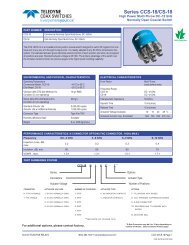
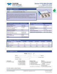
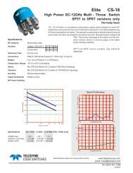
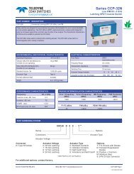
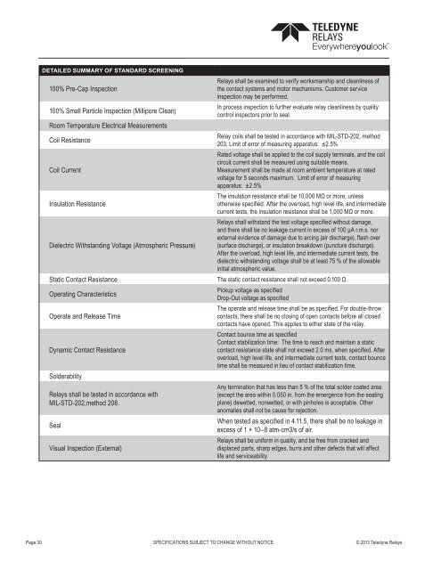
DETAILED SUMMARY OF STANDARD SCREENING<br />
100% Pre-Cap Inspection<br />
100% Small Particle Inspection (Millipore Clean)<br />
Room Temperature Electrical Measurements<br />
Coil Resistance<br />
Coil Current<br />
Insulation Resistance<br />
<strong>Relays</strong> shall be examined to verify worksmanship and cleanliness of<br />
the contact systems and motor mechanisms. Customer service<br />
inspection may be performed.<br />
In process inspection to further evaluate relay cleanliness by quality<br />
control inspectors prior to seal.<br />
Relay coils shall be tested in accordance with MIL-STD-202, method<br />
203. Limit of error of measuring apparatus: ±2.5%<br />
Rated voltage shall be applied to the coil supply terminals, and the coil<br />
circuit current shall be measured using suitable means.<br />
Measurement shall be made at room ambient temperature at rated<br />
voltage for 5 seconds maximum. Limit of error of measuring<br />
apparatus: ±2.5%<br />
The insulation resistance shall be 10,000 MΩ or more, unless<br />
otherwise specified. After the overload, high level life, and intermediate<br />
current tests, the insulation resistance shall be 1,000 MΩ or more.<br />
<strong>Relays</strong> shall withstand the test voltage specified without damage,<br />
and there shall be no leakage current in excess of 100 μA r.m.s. nor<br />
external evidence of damage due to arcing (air discharge), flash over<br />
Dielectric Withstanding Voltage (Atmospheric Pressure) (surface discharge), or insulation breakdown (puncture discharge).<br />
After the overload, high level life, and intermediate current tests, the<br />
dielectric withstanding voltage shall be at least 75 % of the allowable<br />
initial atmospheric value.<br />
Static Contact Resistance The static contact resistance shall not exceed 0.100 Ω.<br />
Operating Characteristics<br />
Operate and Release Time<br />
Dynamic Contact Resistance<br />
Solderability<br />
<strong>Relays</strong> shall be tested in accordance with<br />
MIL-STD-202,method 208.<br />
Seal<br />
Visual Inspection (External)<br />
Pickup voltage as specified<br />
Drop-Out voltage as specified<br />
The operate and release time shall be as specified. For double-throw<br />
contacts, there shall be no closing of open contacts before all closed<br />
contacts have opened. This applies to either state of the relay.<br />
Contact bounce time as specified<br />
Contact stabilization time: The time to reach and maintain a static<br />
contact resistance state shall not exceed 2.0 ms, when specified. After<br />
overload, high level life, and intermediate current tests, contact bounce<br />
time shall be measured in lieu of contact stabilization time.<br />
Any termination that has less than 5 % of the total solder coated area<br />
(except the area within 0.050 in. from the emergence from the seating<br />
plane) dewetted, nonwetted, or with pinholes is acceptable. Other<br />
anomalies shall not be cause for rejection.<br />
When tested as specified in 4.11.5, there shall be no leakage in<br />
excess of 1 × 10⁻⁸ atm-cm3/s of air.<br />
<strong>Relays</strong> shall be uniform in quality, and be free from cracked and<br />
displaced parts, sharp edges, burrs and other defects that will affect<br />
life and serviceability<br />
Page 30 SPECIFICATIONS SUBJECT TO CHANGE WITHOUT NOTICE © 2013 <strong>Teledyne</strong> <strong>Relays</strong>