Download our Space Databook - Teledyne Relays
Download our Space Databook - Teledyne Relays
Download our Space Databook - Teledyne Relays

Create successful ePaper yourself
Turn your PDF publications into a flip-book with our unique Google optimized e-Paper software.
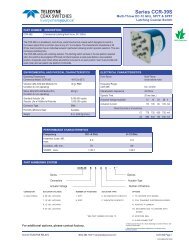
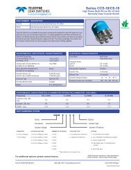
Series H-47N<br />
DC up to 12 GHz<br />
Latching Transfer <strong>Space</strong> Grade Coaxial Switch<br />
COAX SWITCHES<br />
PART NUMBER<br />
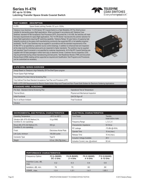
H-47N<br />
DESCRIPTION<br />
<strong>Space</strong> Grade Latching Transfer, DC up to 12GHz<br />
<strong>Teledyne</strong> Coax Switches’ “H-47N Series” RF Coaxial Switch is a High Reliability Off-The-Shelf product<br />
suitable for demanding space flight applications. When purchased in accordance with <strong>Teledyne</strong> Coax<br />
Switches’ standard Hi-Rel Acceptance Test Procedure (ATP), Document No. 0-43-058, the switches will meet<br />
the basic requirements for space flight applications. The “H-47N Series” has become the premier selection for<br />
space flight applications requiring RF switching capability. <strong>Teledyne</strong> <strong>Relays</strong>’ 50 year history of supplying high<br />
reliability products to the space craft manufacturing community has supported 95% of all satellite programs<br />
worldwide. The RF Coax Switches may be supplied in accordance with the standard requirements of the<br />
Hi-Rel ATP or as specified by customer s<strong>our</strong>ce control drawings. In addition to enhanced test and inspection<br />
at the relay level the individual piece parts are inspected to higher standards. The switches may be supplied<br />
with standard Type N connector or as specified by customer requirements. All Hi-Rel RF Coaxial Switches are<br />
supplied with full data packages in either hard copy or electronic format. Customer S<strong>our</strong>ce Inspection (CSI)<br />
may be performed during critical manufacturing and test points. Test Readiness Review (TRR) and Document<br />
Review Board (DRB) meeting will be supported as required and Qualification Test Programs and Procedures<br />
can be customized as necessary.<br />
H-47N HIREL SERIES OVERVIEW<br />
Design Based on <strong>Teledyne</strong>’s High Reliability Off-The-Shelf <strong>Space</strong> program<br />
Proven <strong>Space</strong> Flight Heritage<br />
Fully Defined Pre-Seal Internal Screening Plan<br />
Fully Defined Post-Seal Standard Acceptance Test Plan and Procedure (ATP)<br />
ANSI-J-STD-006 Requirements for Electric Grade Solder Alloys and Fluxed and Non-Fluxed Solid Solders for Electronic Soldering Applications<br />
STANDARD HIREL SCREENING<br />
Pre-Seal - Standard Internal Screening Plan<br />
Operational Test at Temperature<br />
Thermal Shock<br />
Physical and Mechanical Inspection<br />
Initial Functional<br />
QA/CSI Sign-off<br />
Run-In at Room Ambient<br />
Final Functional<br />
Vibration<br />
ENVIRONMENTAL AND PHYSICAL CHARACTERISTICS<br />
Operating Temperature<br />
–55°C to +85°C<br />
Vibration (MIL-STD-202 Method 214,<br />
10 g’s RMS<br />
Condition D, non-operating)<br />
Shock (MIL-STD-202 Method 213,<br />
500 g’s<br />
Condition D, non-operating)<br />
Finish<br />
Electroless Nickel Plate<br />
Life Cycle, minimum<br />
100,000 cycles<br />
Connector Type<br />
Type N<br />
Weight<br />
6.5 oz. (184.27g) (max.)<br />
ELECTRICAL CHARACTERISTICS<br />
Form Factor<br />
Frequency Range<br />
Characteristic Impedance<br />
RF Leakage<br />
Operate Time<br />
Release Time<br />
Actuation Voltage Available<br />
Actuation Current, max. @ ambient<br />
Transfer,<br />
break before make<br />
L, S, C, X<br />
50 Ohms<br />
-70 dBc @ 4GHz<br />
10 ms (max.)<br />
10 ms (max.)<br />
28 V<br />
90 mA<br />
PERFORMANCE CHARACTERISTICS<br />
Frequency Option F2 (L-BAND)<br />
DC–2 GHz<br />
F4 (S-BAND)<br />
2–4 GHz<br />
F8 (C-BAND)<br />
4–8 GHz<br />
F12 (X-BAND)<br />
8–12 GHz<br />
Insertion Loss, dB,<br />
max.<br />
0.2 0.3 0.4 0.6<br />
Isolation, dB, min. 70 70 60 60<br />
VSWR , max. 1.3:1 1.3:1 1.4:1 1.65:1<br />
Page 40 SPECIFICATIONS SUBJECT TO CHANGE WITHOUT NOTICE © 2013 <strong>Teledyne</strong> <strong>Relays</strong>