CCRT-53S FAILSAFE - SHORT.indd - Teledyne Coax Switches
CCRT-53S FAILSAFE - SHORT.indd - Teledyne Coax Switches
CCRT-53S FAILSAFE - SHORT.indd - Teledyne Coax Switches

You also want an ePaper? Increase the reach of your titles
YUMPU automatically turns print PDFs into web optimized ePapers that Google loves.
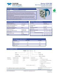
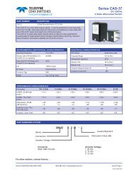
COAX SWITCHESSeries <strong>CCRT</strong>-<strong>53S</strong>/CRT-<strong>53S</strong>Internal 50Ω Termination DC-26.5 GHzFailsafe SPDT <strong>Coax</strong>ial SwitchPART NUMBER<strong>CCRT</strong>-<strong>53S</strong>CRT-<strong>53S</strong>DESCRIPTIONCommercial Failsafe SPDT, DC-26.5GHz, Internal 50Ω TerminationElite Failsafe SPDT, DC-26.5GHz, Internal 50Ω TerminationThe <strong>CCRT</strong>-<strong>53S</strong>/CRT-<strong>53S</strong> is an internally terminated, broadband, SPDT, electromechanical coaxial switchdesigned to switch a microwave signal from a common input to either of two outputs. The characteristicimpedance is 50 Ohms. Internal terminations provide an impedance match for the unselected port. Theswitches are small with the minimum spacing that is compatible with SMA connectors.ENVIRONMENTAL AND PHYSICAL CHARACTERISTICSOperating TemperatureCommercial Model, <strong>CCRT</strong>-<strong>53S</strong>Elite Model, CRT-<strong>53S</strong>Vibration (MIL-STD-202 Method 214,Condition D, non-operating)Shock (MIL-STD-202 Method 213,Condition D, non-operating)Standard Actuator LifeActuator Life w/ Additional FeaturesConnector TypeHumidity (Moisture Seal)Weight–40°C to 65°C–55°C to 85°C10 g’s RMS500 g’s5,000,000 cycles1,000,000 cyclesSMAAvailable2.65 oz. (75.13g) (max.)ELECTRICAL CHARACTERISTICSForm FactorFrequency Range<strong>CCRT</strong>-<strong>53S</strong>CRT-<strong>53S</strong>Characteristic ImpedanceTerminationsOperate TimeRelease TimeSPDT,break before makeDC–26.5 GHzDC–26.5 GHz50 Ohms50Ω, 2 Watts CW max.10 ms (max.)10 ms (max.)Actuation Voltage Available 12 15 24 28 VActuation Current, max. @ ambient 420 350 280 200 mAPERFORMANCE CHARACTERISTICSFrequency DC–6 GHz 6–12 GHz 12–18 GHz 18–22 GHz 22–26.5 GHzInsertion Loss, dB,max.0.2 0.3 0.4 0.5 0.6Isolation, dB, min. 80 75 70 70 55VSWR , max. 1.1:1 1.2:1 1.3:1 1.5:1 1.6:1PART NUMBERING SYSTEM<strong>CCRT</strong>-53 S 1 C - T **SeriesConnectorsOptionsActuator TypeActuator VoltageConnectorS: SMA FemaleActuator Voltage1: 28 Vdc Failsafe2: 15 Vdc Failsafe3: 12 Vdc Failsafe4: 24 Vdc FailsafeActuator Type0: Standard ContactsC: Indicator Contacts**SEE PARTS LIST ON PAGE 8OptionsT: TTL Drivers with DiodesD: Transient SuppressionDiodesM: Moisture SealS: 9 Pin D-Sub ConnectorFor other options, contact factory.© 2013 TELEDYNE RELAYS (800) 284-7007 • www.teledynecoax.com <strong>CCRT</strong>-<strong>53S</strong>/CRT-<strong>53S</strong> Page 1<strong>CCRT</strong>-<strong>53S</strong>\CRT-<strong>53S</strong>\082013\Q3
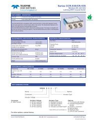
Series <strong>CCRT</strong>-<strong>53S</strong>/CRT-<strong>53S</strong>Internal 50Ω Termination DC-26.5 GHzFailsafe SPDT <strong>Coax</strong>ial SwitchCOAX SWITCHESSCHEMATICS AND MECHANICAL OUTLINEH = 1.75 MAX. STD & Indicator ModelH = 1.90 MAX. TTL ModelH = 2.05 MAX. 9-Pin D-Sub ModelIndicatorsTTLAnalog16“-S OPTION” 9-PIN D-SUB CONNECTOR (EXAMPLE: <strong>CCRT</strong>-<strong>53S</strong>10-S)9 PIN D-SUB PINOUT FOR <strong>FAILSAFE</strong> SPDTOPTIONSPinBasic Indicators TTLNo.Indicators &TTL1 + +2 - -3 Common Common4 1 156 Vsw Vsw7 A A8 B B9 C CTRUTH TABLE (with TTL option)LogicInput1 INto 1RF PathINto 2Indicator(if applicable)0 OnTerminatedC 01TerminatedOn 0 CAB<strong>CCRT</strong>-<strong>53S</strong>/CRT-<strong>53S</strong> Page 2 SPECIFICATIONS ARE SUBJECT TO CHANGE WITHOUT NOTICE © 2013 TELEDYNE COAX SWITCHES<strong>CCRT</strong>-<strong>53S</strong>\CRT-<strong>53S</strong>\082013\Q3
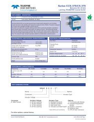
COAX SWITCHESSeries <strong>CCRT</strong>-<strong>53S</strong>/CRT-<strong>53S</strong>Internal 50Ω Termination DC-26.5 GHzFailsafe SPDT <strong>Coax</strong>ial SwitchTYPICAL NARROWBAND RF INSERTION LOSS PERFORMANCE CURVESInsertion Loss ( DC-6 GHz )Insertion Loss ( 6-12 GHz )Insertion Loss (dB)0.0-0.1-0.2-0.3-0.4-0.5-0.6-0.7-0.8-0.9-1.00 1 2 3 4 5 6Frequency (GHz)Insertion Loss (dB)0.0-0.1-0.2-0.3-0.4-0.5-0.6-0.7-0.8-0.9-1.06 7 8 9 10 11 12Frequency (GHz)Insertion Loss ( 12-18 GHz )Insertion Loss ( 18-22 GHz )Insertion Loss (dB)0.0-0.1-0.2-0.3-0.4-0.5-0.6-0.7-0.8-0.9-1.012 13 14 15 16 17 18Frequency (GHz)Insertion Loss (dB)0.0-0.1-0.2-0.3-0.4-0.5-0.6-0.7-0.8-0.9-1.018 19 20 21 22Frequency (GHz)Insertion Loss ( 22-26.5 GHz )Insertion Loss (dB)0.0-0.1-0.2-0.3-0.4-0.5-0.6-0.7-0.8-0.9-1.022 23 24 25 26Frequency (GHz)RF NOTES© 2013 TELEDYNE RELAYS (800) 284-7007 • www.teledynecoax.com <strong>CCRT</strong>-<strong>53S</strong>/CRT-<strong>53S</strong> Page 3<strong>CCRT</strong>-<strong>53S</strong>\CRT-<strong>53S</strong>\082013\Q3
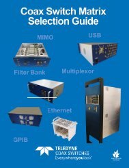
Series <strong>CCRT</strong>-<strong>53S</strong>/CRT-<strong>53S</strong>Internal 50Ω Termination DC-26.5 GHzFailsafe SPDT <strong>Coax</strong>ial SwitchCOAX SWITCHESTYPICAL NARROWBAND RF ISOLATION PERFORMANCE CURVES0Isolation ( DC-6 GHz )0Isolation ( 6-12 GHz )-20-20-40-40Isolation (dB)-60-80-100Isolation (dB)-60-80-100-120-120-1400 1 2 3 4 5 6Frequency (GHz)-1406 7 8 9 10 11 12Frequency (GHz)0Isolation ( 12-18 GHz )0Isolation ( 18-22 GHz )-20-20-40-40Isolation (dB)-60-80-100Isolation (dB)-60-80-100-120-120-14012 13 14 15 16 17 18Frequency (GHz)-14018 18.5 19 19.5 20 20.5 21 21.5 22Frequency (GHz)0Isolation ( 22-26.5 GHz )-20Isolation (dB)-40-60-80-100-120-14022 22.5 23 23.5 24 24.5 25 25.5 26 26.5Frequency (GHz)RF NOTES<strong>CCRT</strong>-<strong>53S</strong>/CRT-<strong>53S</strong> Page 4 SPECIFICATIONS ARE SUBJECT TO CHANGE WITHOUT NOTICE © 2013 TELEDYNE COAX SWITCHES<strong>CCRT</strong>-<strong>53S</strong>\CRT-<strong>53S</strong>\082013\Q3
COAX SWITCHESSeries <strong>CCRT</strong>-<strong>53S</strong>/CRT-<strong>53S</strong>Internal 50Ω Termination DC-26.5 GHzFailsafe SPDT <strong>Coax</strong>ial SwitchTYPICAL NARROWBAND RF VSWR PERFORMANCE CURVES2.0VSWR ( DC-6 GHz )2.0VSWR ( 6-12 GHz )1.91.91.81.81.71.7VSWR1.61.51.4VSWR1.61.51.41.31.31.21.21.11.11.00 1 2 3 4 5 6Frequency (GHz)1.06 7 8 9 10 11 12Frequency (GHz)2.0VSWR ( 12-18 GHz )2.0VSWR ( 18-22 GHz )1.91.91.81.81.71.7VSWR1.61.51.4VSWR1.61.51.41.31.31.21.21.11.11.012 13 14 15 16 17 18Frequency (GHz)1.018 18.5 19 19.5 20 20.5 21 21.5 22Frequency (GHz)2.0VSWR ( 22-26.5 GHz )VSWR1.91.81.71.61.51.41.31.21.11.022 22.5 23 23.5 24 24.5 25 25.5 26 26.5Frequency (GHz)RF NOTES© 2013 TELEDYNE RELAYS (800) 284-7007 • www.teledynecoax.com <strong>CCRT</strong>-<strong>53S</strong>/CRT-<strong>53S</strong> Page 5<strong>CCRT</strong>-<strong>53S</strong>\CRT-<strong>53S</strong>\082013\Q3
Series <strong>CCRT</strong>-<strong>53S</strong>/CRT-<strong>53S</strong>Internal 50Ω Termination DC-26.5 GHzFailsafe SPDT <strong>Coax</strong>ial SwitchCOAX SWITCHESTYPICAL POWER PERFORMANCE CURVEPower Handling vs. Frequency300020001000800600Power (W)4003002001008060STANDARD SMA SWITCHES40302010.1 .2 .3 .4 .6 .8 1 2 4 6 8 10 18 26.5Frequency GHzEstimates based on the following reference conditions:• Ambient temperature of 40°C or less• Sea level operation• Load VSWR of 1.20:1 maximum• No high-power (hot) switchingPlease contact <strong>Teledyne</strong> <strong>Coax</strong> <strong>Switches</strong> for derating factors when applications do not meet the foregoing reference conditions.<strong>CCRT</strong>-<strong>53S</strong>/CRT-<strong>53S</strong> Page 6 SPECIFICATIONS ARE SUBJECT TO CHANGE WITHOUT NOTICE © 2013 TELEDYNE COAX SWITCHES<strong>CCRT</strong>-<strong>53S</strong>\CRT-<strong>53S</strong>\082013\Q3
COAX SWITCHESSeries <strong>CCRT</strong>-<strong>53S</strong>/CRT-<strong>53S</strong>Internal 50Ω Termination DC-26.5 GHzFailsafe SPDT <strong>Coax</strong>ial SwitchGLOSSARYActuatorAn actuator is the electromechanical mechanism thattransfers the RF contacts from one position to another uponDC command.Arc Suppression DiodeA diode is connected in parallel with the coil. This diodelimits the “reverse EMF spike” generated when the coil deenergizesto 0.7 volts. The diode cathode is connected tothe positive side of the coil and the anode is connected tothe negative side.Date CodeAll switches are marked with either a unique serial numberor a date code. Date codes are in accordance with MIL-STD-1285 Paragraph 5.2.5 and consist of four digits.The fi rst two digits defi ne the year and the last two digitsdefi ne the week of the year (YYWW). Thus, 1032 identifi esswitches that passed through fi nal inspection during the32nd week of 2010.FailsafeA failsafe switch reverts to the default or failsafe positionwhen actuating voltage is removed. This is realized by areturn spring within the drive mechanism. This type of switchrequires the continuous application of operating voltage toselect and hold any position. (Multi-position switches arenormally open with no voltage applied).IndicatorIndicators tell the system which position the switch is in.Other names for indicators are telemetry contacts or tellbackcircuit. Indicators are usually a set of internally mounted DCcontacts linked to the actuator. They can be wired to digitalinput lines, status lights, or interlocks. Unless otherwisespecifi ed, the maximum indicator contact rating is 30 Vdc,50 mA, or 1.5 Watts into a resistive load.Internal TerminationUnselected ports are internally terminated to a matchedload. The load is 50Ω resistive device. The max RF powerrating is 2 Watts CW. Without the internal termination option,the unselected ports are open circuits.IsolationIsolation is the measure of the power level at the outputconnector of an unconnected RF channel as referenced tothe power at the input connector. It is specifi ed in dB belowthe input power level.SPDT SwitchA single-pole double-throw, bi-directional switch that canbe used as having one input and two outputs or two inputsand one output.Switching TimeSwitching time is the total interval beginning with the arrivalof the leading edge of the command pulse at the switch DCinput and ending with the completion of the switch transfer,including contact bounce. It consists of three parts: (1)inductive delay in the coil, (2) transfer time of the physicalmovement of the contacts, and (3) the bounce time of theRF contacts.TTL Switch Driver OptionAs a special option, switch drivers can be provided for bothfailsafe and latching switches, which are compatible withindustry-standard low-power Schottky TTL circuits.Performance Parameters vs FrequencyGenerally speaking, the RF performance of coaxial switchesis frequency dependent. With increasing frequency, VSWRand insertion loss increase while isolation decreases. Alldata sheets specify these three parameters as “worst case”at the highest operating frequency. If the switch is to beused over a narrow frequency band, better performancecan be achieved.Actuator Current vs TemperatureThe resistance of the actuator coil varies as a function oftemperature. There is an inverse relationship between theoperating temperature of the switch and the actuator drivecurrent. For switches operating at 28 VDC, the approximateactuator drive current at temperature, T, can be calculatedusing the equation:I T=Where:I A[1 + .00385 (T-20)]I T= Actuator current at temperature, TI A= Room temperature actuator current –see data sheetT = Temperature of interest in °CMagnetic SensitivityAn electro-mechanical switch can be sensitive to ferrousmaterials and external magnetic fi elds. Neighboring ferrousmaterials should be permitted no closer than 0.5 inches andadjacent external magnetic fi elds should be limited to a fl uxdensity of less than 5 Gauss.SPECIAL FEATURESwitching High-Power or Highly Sensitive SignalsEnsure the most linear response with the best galvanicallymatched contact system in the industry. Extremely lowpassive intermodulation is standard on all of our switches.CarrierFrequency 1CarrierFrequency 2PIM 3rd OrderFrequencyPIM 5thOrder Frequency870 MHz 893 MHz 847 MHz 824 MHzSPDT3rd OrderIntermodulation5th OrderIntermodulation–91 dBm –110 dBm–134 dBc –153 dBc© 2013 TELEDYNE RELAYS (800) 284-7007 • www.teledynecoax.com <strong>CCRT</strong>-<strong>53S</strong>/CRT-<strong>53S</strong> Page 7<strong>CCRT</strong>-<strong>53S</strong>\CRT-<strong>53S</strong>\082013\Q3
Series <strong>CCRT</strong>-<strong>53S</strong>/CRT-<strong>53S</strong>Internal 50Ω Termination DC-26.5 GHzFailsafe SPDT <strong>Coax</strong>ial SwitchCOAX SWITCHES<strong>FAILSAFE</strong> <strong>CCRT</strong>-<strong>53S</strong>/CRT-<strong>53S</strong> PART NUMBER LISTPART NO. PART NO. PART NO.1 <strong>CCRT</strong>-<strong>53S</strong>XC 43 <strong>CCRT</strong>-<strong>53S</strong>X0 85 CRT-<strong>53S</strong>XD-MS2 <strong>CCRT</strong>-<strong>53S</strong>XC-D 44 <strong>CCRT</strong>-<strong>53S</strong>X0-D 86 CRT-<strong>53S</strong>XD-R3 <strong>CCRT</strong>-<strong>53S</strong>XC-DM 45 <strong>CCRT</strong>-<strong>53S</strong>X0-DM 87 CRT-<strong>53S</strong>XD-RM4 <strong>CCRT</strong>-<strong>53S</strong>XC-DMS 46 <strong>CCRT</strong>-<strong>53S</strong>X0-DMS 88 CRT-<strong>53S</strong>XD-RMS5 <strong>CCRT</strong>-<strong>53S</strong>XC-DR 47 <strong>CCRT</strong>-<strong>53S</strong>X0-DR 89 CRT-<strong>53S</strong>XD-RS6 <strong>CCRT</strong>-<strong>53S</strong>XC-DRM 48 <strong>CCRT</strong>-<strong>53S</strong>X0-DRM 90 CRT-<strong>53S</strong>XD-S7 <strong>CCRT</strong>-<strong>53S</strong>XC-DRMS 49 <strong>CCRT</strong>-<strong>53S</strong>X0-DRMS 91 CRT-<strong>53S</strong>XD-T8 <strong>CCRT</strong>-<strong>53S</strong>XC-DRS 50 <strong>CCRT</strong>-<strong>53S</strong>X0-DRS 92 CRT-<strong>53S</strong>XD-TM9 <strong>CCRT</strong>-<strong>53S</strong>XC-DS 51 <strong>CCRT</strong>-<strong>53S</strong>X0-DS 93 CRT-<strong>53S</strong>XD-TMS10 <strong>CCRT</strong>-<strong>53S</strong>XC-M 52 <strong>CCRT</strong>-<strong>53S</strong>X0-M 94 CRT-<strong>53S</strong>XE11 <strong>CCRT</strong>-<strong>53S</strong>XC-MS 53 <strong>CCRT</strong>-<strong>53S</strong>X0-MS 95 CRT-<strong>53S</strong>XE-M12 <strong>CCRT</strong>-<strong>53S</strong>XC-R 54 <strong>CCRT</strong>-<strong>53S</strong>X0-R 96 CRT-<strong>53S</strong>XE-MS13 <strong>CCRT</strong>-<strong>53S</strong>XC-RM 55 <strong>CCRT</strong>-<strong>53S</strong>X0-RM 97 CRT-<strong>53S</strong>XE-R14 <strong>CCRT</strong>-<strong>53S</strong>XC-RMS 56 <strong>CCRT</strong>-<strong>53S</strong>X0-RMS 98 CRT-<strong>53S</strong>XE-RM15 <strong>CCRT</strong>-<strong>53S</strong>XC-RS 57 <strong>CCRT</strong>-<strong>53S</strong>X0-RS 99 CRT-<strong>53S</strong>XE-RMS16 <strong>CCRT</strong>-<strong>53S</strong>XC-S 58 <strong>CCRT</strong>-<strong>53S</strong>X0-S 100 CRT-<strong>53S</strong>XE-RS17 <strong>CCRT</strong>-<strong>53S</strong>XC-T 59 <strong>CCRT</strong>-<strong>53S</strong>X0-T 101 CRT-<strong>53S</strong>XE-S18 <strong>CCRT</strong>-<strong>53S</strong>XC-TM 60 <strong>CCRT</strong>-<strong>53S</strong>X0-TM 102 CRT-<strong>53S</strong>XE-T19 <strong>CCRT</strong>-<strong>53S</strong>XC-TMS 61 <strong>CCRT</strong>-<strong>53S</strong>X0-TMS 103 CRT-<strong>53S</strong>XE-TM20 <strong>CCRT</strong>-<strong>53S</strong>XC-TS 62 <strong>CCRT</strong>-<strong>53S</strong>X0-TS 104 CRT-<strong>53S</strong>XE-TMS21 <strong>CCRT</strong>-<strong>53S</strong>XD 63 CRT-<strong>53S</strong>XC 105 CRT-<strong>53S</strong>X022 <strong>CCRT</strong>-<strong>53S</strong>XD-M 64 CRT-<strong>53S</strong>XC-D 106 CRT-<strong>53S</strong>X0-D23 <strong>CCRT</strong>-<strong>53S</strong>XD-MS 65 CRT-<strong>53S</strong>XC-DM 107 CRT-<strong>53S</strong>X0-DM24 <strong>CCRT</strong>-<strong>53S</strong>XD-R 66 CRT-<strong>53S</strong>XC-DMS 108 CRT-<strong>53S</strong>X0-DMS25 <strong>CCRT</strong>-<strong>53S</strong>XD-RM 67 CRT-<strong>53S</strong>XC-DR 109 CRT-<strong>53S</strong>X0-DR26 <strong>CCRT</strong>-<strong>53S</strong>XD-RMS 68 CRT-<strong>53S</strong>XC-DRM 110 CRT-<strong>53S</strong>X0-DRM27 <strong>CCRT</strong>-<strong>53S</strong>XD-RS 69 CRT-<strong>53S</strong>XC-DRMS 111 CRT-<strong>53S</strong>X0-DRMS28 <strong>CCRT</strong>-<strong>53S</strong>XD-S 70 CRT-<strong>53S</strong>XC-DRS 112 CRT-<strong>53S</strong>X0-DRS29 <strong>CCRT</strong>-<strong>53S</strong>XD-T 71 CRT-<strong>53S</strong>XC-DS 113 CRT-<strong>53S</strong>X0-DS30 <strong>CCRT</strong>-<strong>53S</strong>XD-TM 72 CRT-<strong>53S</strong>XC-M 114 CRT-<strong>53S</strong>X0-M31 <strong>CCRT</strong>-<strong>53S</strong>XD-TMS 73 CRT-<strong>53S</strong>XC-MS 115 CRT-<strong>53S</strong>X0-MS32 <strong>CCRT</strong>-<strong>53S</strong>XE 74 CRT-<strong>53S</strong>XC-R 116 CRT-<strong>53S</strong>X0-R33 <strong>CCRT</strong>-<strong>53S</strong>XE-M 75 CRT-<strong>53S</strong>XC-RM 117 CRT-<strong>53S</strong>X0-RM34 <strong>CCRT</strong>-<strong>53S</strong>XE-MS 76 CRT-<strong>53S</strong>XC-RMS 118 CRT-<strong>53S</strong>X0-RMS35 <strong>CCRT</strong>-<strong>53S</strong>XE-R 77 CRT-<strong>53S</strong>XC-RS 119 CRT-<strong>53S</strong>X0-RS36 <strong>CCRT</strong>-<strong>53S</strong>XE-RM 78 CRT-<strong>53S</strong>XC-S 120 CRT-<strong>53S</strong>X0-S37 <strong>CCRT</strong>-<strong>53S</strong>XE-RMS 79 CRT-<strong>53S</strong>XC-T 121 CRT-<strong>53S</strong>X0-T38 <strong>CCRT</strong>-<strong>53S</strong>XE-RS 80 CRT-<strong>53S</strong>XC-TM 122 CRT-<strong>53S</strong>X0-TM39 <strong>CCRT</strong>-<strong>53S</strong>XE-S 81 CRT-<strong>53S</strong>XC-TMS 123 CRT-<strong>53S</strong>X0-TMS40 <strong>CCRT</strong>-<strong>53S</strong>XE-T 82 CRT-<strong>53S</strong>XC-TS 124 CRT-<strong>53S</strong>X0-TS41 <strong>CCRT</strong>-<strong>53S</strong>XE-TM 83 CRT-<strong>53S</strong>XD42 <strong>CCRT</strong>-<strong>53S</strong>XE-TMS 84 CRT-<strong>53S</strong>XD-M* X = 1 (28Vdc), 2 (15Vdc), 3 (12Vdc) and 4 (24Vdc)<strong>CCRT</strong>-<strong>53S</strong>/CRT-<strong>53S</strong> Page 8 SPECIFICATIONS ARE SUBJECT TO CHANGE WITHOUT NOTICE © 2013 TELEDYNE COAX SWITCHES<strong>CCRT</strong>-<strong>53S</strong>\CRT-<strong>53S</strong>\082013\Q3