63696870_V20_at_S7-1200_USS_v10_SHORT ... - Siemens
63696870_V20_at_S7-1200_USS_v10_SHORT ... - Siemens
63696870_V20_at_S7-1200_USS_v10_SHORT ... - Siemens

You also want an ePaper? Increase the reach of your titles
YUMPU automatically turns print PDFs into web optimized ePapers that Google loves.
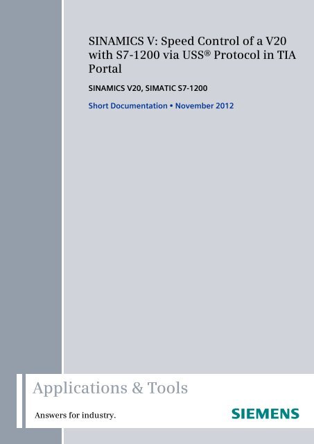
Cover<br />
SINAMICS V: Speed Control of a <strong>V20</strong><br />
with <strong>S7</strong>-<strong>1200</strong> via <strong>USS</strong>® Protocol in TIA<br />
Portal<br />
SINAMICS <strong>V20</strong>, SIMATIC <strong>S7</strong>-<strong>1200</strong><br />
Short Document<strong>at</strong>ion • November 2012<br />
Applic<strong>at</strong>ions & Tools<br />
Answers for industry.
<strong>Siemens</strong> Industry Online Support<br />
This document is taken from <strong>Siemens</strong> Industry Online Support. The following link<br />
takes you directly to the download page of this document:<br />
http://support.autom<strong>at</strong>ion.siemens.com/WW/view/en/<strong>63696870</strong><br />
Caution:<br />
The functions and solutions described in this entry are mainly limited to the<br />
realiz<strong>at</strong>ion of the autom<strong>at</strong>ion task. In addition, please note th<strong>at</strong> suitable security<br />
measures in compliance with the applicable Industrial Security standards must be<br />
taken, if your system is interconnected with other parts of the plant, the company’s<br />
network or the Internet. For further inform<strong>at</strong>ion on this issue, please refer to Entry<br />
ID 50203404.<br />
http://support.autom<strong>at</strong>ion.siemens.com/WW/view/en/50203404.<br />
Copyright <strong>Siemens</strong> AG 2012 All rights reserved<br />
For further inform<strong>at</strong>ion on this topic, you may also actively use our Technical<br />
Forum in the <strong>Siemens</strong> Industry Online Support. Share your questions, suggestions<br />
or problems and discuss them with our strong forum community:<br />
http://www.siemens.com/forum-applic<strong>at</strong>ions<br />
2<br />
SINAMICS <strong>V20</strong> to <strong>S7</strong>-<strong>1200</strong> via <strong>USS</strong><br />
V1.0, Entry ID: <strong>63696870</strong>
s<br />
Overview 1<br />
Program Structure 2<br />
<strong>V20</strong>_<strong>USS</strong>_Control_1 [FB1]<br />
block 3<br />
SIMATIC, SINAMICS<br />
<strong>USS</strong> communic<strong>at</strong>ion between a<br />
SINAMICS <strong>V20</strong> drive and a<br />
SIMATIC <strong>S7</strong>-<strong>1200</strong> PLC<br />
<strong>V20</strong>_<strong>USS</strong>_Param_1 [FB2]<br />
block 4<br />
Expansion to Several<br />
Ports 5<br />
Liter<strong>at</strong>ure 6<br />
Copyright <strong>Siemens</strong> AG 2012 All rights reserved<br />
History 7<br />
SINAMICS <strong>V20</strong> to <strong>S7</strong>-<strong>1200</strong> via <strong>USS</strong><br />
V1.0, Entry ID: <strong>63696870</strong> 3
Warranty and Liability<br />
Warranty and Liability<br />
Note<br />
The applic<strong>at</strong>ion examples are not binding and do not claim to be complete with<br />
regard to configur<strong>at</strong>ion, equipment or any contingencies. The applic<strong>at</strong>ion<br />
examples do not represent customer-specific solutions. They are only intended<br />
to provide support for typical applic<strong>at</strong>ions. You are responsible for ensuring th<strong>at</strong><br />
the described products are used correctly. These applic<strong>at</strong>ion examples do not<br />
relieve you of your responsibility to use sound practices in applic<strong>at</strong>ion,<br />
install<strong>at</strong>ion, oper<strong>at</strong>ion and maintenance. When using these applic<strong>at</strong>ion examples,<br />
you recognize th<strong>at</strong> we will not be liable for any damage/claims beyond the<br />
liability clause described. We reserve the right to make changes to these<br />
applic<strong>at</strong>ion examples <strong>at</strong> any time and without prior notice. If there are any<br />
devi<strong>at</strong>ions between the recommend<strong>at</strong>ions provided in this applic<strong>at</strong>ion example<br />
and other <strong>Siemens</strong> public<strong>at</strong>ions – e.g. c<strong>at</strong>alogs – the contents of the other<br />
documents have priority.<br />
Copyright <strong>Siemens</strong> AG 2012 All rights reserved<br />
We accept no liability for inform<strong>at</strong>ion contained in this document.<br />
Any claims against us – based on wh<strong>at</strong>ever legal reason – resulting from the use of the<br />
examples, inform<strong>at</strong>ion, programs, engineering and performance d<strong>at</strong>a etc., described in this<br />
Applic<strong>at</strong>ion Example shall be excluded. Such an exclusion shall not apply in the case of<br />
mand<strong>at</strong>ory liability, e.g. under the German Product Liability Act (“Produkthaftungsgesetz”),<br />
in case of intent, gross negligence, or injury of life, body or health, guarantee for the quality<br />
of a product, fraudulent concealment of a deficiency or breach of a condition which goes to<br />
the root of the contract (“wesentliche Vertragspflichten”). The damages for a breach of a<br />
substantial contractual oblig<strong>at</strong>ion are, however, limited to the foreseeable damage, typical<br />
for the type of contract, except in the event of intent or gross negligence or injury to life,<br />
body or health. The above provisions do not imply a change in the burden of proof to your<br />
disadvantage.<br />
It is not permissible to transfer or copy these Applic<strong>at</strong>ion Examples or excerpts thereof<br />
without express authoriz<strong>at</strong>ion from <strong>Siemens</strong> Industry Sector.<br />
4<br />
SINAMICS <strong>V20</strong> to <strong>S7</strong>-<strong>1200</strong> via <strong>USS</strong><br />
V1.0, Entry ID: <strong>63696870</strong>
Table of Contents<br />
Copyright <strong>Siemens</strong> AG 2012 All rights reserved<br />
Table of Contents<br />
Warranty and Liability..............................................................................................4<br />
Table of Contents.....................................................................................................5<br />
1 Overview.........................................................................................................6<br />
1.1 Content .............................................................................................6<br />
1.2 Requirements....................................................................................6<br />
Hardware components.......................................................................6<br />
Control software ................................................................................6<br />
Bus wiring..........................................................................................7<br />
2 Program Structure..........................................................................................8<br />
<strong>USS</strong> system instructions....................................................................8<br />
Calling the <strong>V20</strong>_<strong>USS</strong>_Control_1 [FB1] in two OBs.............................8<br />
Block rel<strong>at</strong>ions...................................................................................8<br />
3 <strong>V20</strong>_<strong>USS</strong>_Control_1 [FB1] block ...................................................................9<br />
Configur<strong>at</strong>ion.....................................................................................9<br />
4 <strong>V20</strong>_<strong>USS</strong>_Param_1 [FB2] block...................................................................11<br />
4.1 Oper<strong>at</strong>ing modes.............................................................................11<br />
ACTIVATE_<strong>USS</strong> mode....................................................................11<br />
RW_PARAM mode..........................................................................11<br />
ACTUAL_STATE mode ...................................................................12<br />
SET_FUNCTIONS mode.................................................................12<br />
4.2 Configur<strong>at</strong>ion...................................................................................12<br />
5 Expansion to Several Ports..........................................................................16<br />
6 Liter<strong>at</strong>ure ......................................................................................................18<br />
7 History ..........................................................................................................18<br />
SINAMICS <strong>V20</strong> to <strong>S7</strong>-<strong>1200</strong> via <strong>USS</strong><br />
V1.0, Entry ID: <strong>63696870</strong> 5
1 Overview<br />
1.1 Content<br />
1 Overview<br />
1.1 Content<br />
The present short document<strong>at</strong>ion describes two blocks th<strong>at</strong> you can use for the<br />
connection of a SINAMICS <strong>V20</strong> to a SIMATIC <strong>S7</strong>-<strong>1200</strong> via the <strong>USS</strong> ® protocol in<br />
STEP 7 in the TIA portal V11.<br />
This short document<strong>at</strong>ion largely does not use explan<strong>at</strong>ions. It explains the block<br />
parameters and shows the main steps for the integr<strong>at</strong>ion of the blocks in your own<br />
projects.<br />
Table 1-1: Block functions<br />
Block Function Explan<strong>at</strong>ion<br />
<strong>V20</strong>_<strong>USS</strong>_Control_1<br />
(FB1)<br />
cyclic access to<br />
process d<strong>at</strong>a of up<br />
to 16 drives of a<br />
port<br />
Controlling SINAMICS <strong>V20</strong> via selected<br />
STW bits<br />
Specifying setpoint speed<br />
Condition monitoring of the SINAMICS <strong>V20</strong><br />
via selected ZSW bits<br />
Reading of the actual speed value<br />
Copyright <strong>Siemens</strong> AG 2012 All rights reserved<br />
<strong>V20</strong>_<strong>USS</strong>_Param_1<br />
(FB2)<br />
acyclic access to<br />
parameters of up to<br />
16 drives of a port<br />
ACTIVATE_<strong>USS</strong> mode:<br />
Switching the oper<strong>at</strong>ion of the cyclic process<br />
d<strong>at</strong>a access<br />
(BOP <strong>USS</strong>)<br />
RW_PARAM mode:<br />
Reading/writing of any inverter parameter<br />
ACTUAL_STATE mode:<br />
Reading a set of selected st<strong>at</strong>us inform<strong>at</strong>ion<br />
from the inverter.<br />
SET_FUNCTIONS mode:<br />
Specifying a set of selected<br />
modes.<br />
1.2 Requirements<br />
Hardware components<br />
Table 1-2: Hardware components<br />
Component MLFB Firmware<br />
SIMATIC <strong>S7</strong> -<strong>1200</strong> 6E<strong>S7</strong>21… V2.2.0 and higher<br />
CM 1241 (RS485) 6E<strong>S7</strong>241-1CH30-0XB0 V1.0 and higher<br />
CB 1241 (RS485) 6E<strong>S7</strong>241-1CH30-1XB0 -<br />
SINAMICS <strong>V20</strong> 6SL3210-5BE… V3.5 and higher<br />
Control software<br />
STEP 7 BASIC, V11 SP2 Upd<strong>at</strong>e 4<br />
(Blocks cre<strong>at</strong>ed by V11 SP2 Upd<strong>at</strong>e 4).<br />
6<br />
SINAMICS <strong>V20</strong> to <strong>S7</strong>-<strong>1200</strong> via <strong>USS</strong><br />
V1.0, Entry ID: <strong>63696870</strong>
Copyright <strong>Siemens</strong> AG 2012 All rights reserved<br />
1 Overview<br />
1.2 Requirements<br />
Bus wiring<br />
Figure 1-1: Wiring example <strong>USS</strong> ® Bus<br />
PG/PC<br />
Ethernet<br />
L1<br />
L2<br />
L3<br />
SIMATIC <strong>S7</strong>-<strong>1200</strong><br />
0V cable<br />
M TA TRA TRB TB<br />
SINAMICS <strong>V20</strong><br />
120 <br />
1,5 k 470 <br />
PROFIBUS<br />
bus connectors<br />
CM<br />
1241<br />
CM<br />
1241<br />
CM<br />
1241<br />
CB<br />
1241<br />
CPU<br />
…<br />
Port 3<br />
Port 2<br />
Port 1<br />
Port 4<br />
PROFIBUS cable<br />
CM = Communic<strong>at</strong>ion Module, CB = Communic<strong>at</strong>ion Board<br />
Termin<strong>at</strong>e the bus on the side of the controller with 120, as long as you don’t use a PROFIBUS plug with the CM1241.<br />
SINAMICS <strong>V20</strong> to <strong>S7</strong>-<strong>1200</strong> via <strong>USS</strong><br />
V1.0, Entry ID: <strong>63696870</strong> 7
2 Program Structure<br />
2 Program Structure<br />
Figure 2-1: Program structure<br />
<strong>V20</strong>_<strong>USS</strong>_Control_1_DB<br />
[DB1]<br />
<strong>USS</strong>_DRV_DB_1<br />
[DB1071]<br />
Main [OB1]<br />
<strong>V20</strong>_<strong>USS</strong>_Control_1<br />
[FB1]<br />
<strong>USS</strong>_DRV<br />
[FB1071]<br />
<strong>V20</strong>_<strong>USS</strong>_Param_1_DB<br />
[DB2]<br />
<strong>V20</strong>_<strong>USS</strong>_Param_1<br />
[FB2]<br />
<strong>USS</strong>_RPM<br />
[FC1072]<br />
Copyright <strong>Siemens</strong> AG 2012 All rights reserved<br />
Parameters_1<br />
[B10]<br />
Cyclic interrupt<br />
[OB30]<br />
<strong>V20</strong>_<strong>USS</strong>_Control_1_DB<br />
[DB1]<br />
<strong>V20</strong>_<strong>USS</strong>_Control_1<br />
[FB1]<br />
<strong>USS</strong>_WPM<br />
[FC1073]<br />
<strong>USS</strong>_PORT<br />
[FC1070]<br />
<strong>USS</strong> system instructions<br />
In the screen above, the system blocks marked with a padlock, are cre<strong>at</strong>ed by<br />
STEP 7 itself when calling the instructions with the same name by the blocks<br />
<strong>V20</strong>_<strong>USS</strong>_Control_1 and <strong>V20</strong>_<strong>USS</strong>_Param_1.<br />
Calling the <strong>V20</strong>_<strong>USS</strong>_Control_1 [FB1] in two OBs<br />
Block rel<strong>at</strong>ions<br />
As you can seen in Figure 2-1, the <strong>V20</strong>_<strong>USS</strong>_Control_1 [FB1] is to be called in the<br />
cyclic program part (OB1) as well as in an interrupt OB (OB30). You do not have to<br />
configure the time interval of the interrupt. This task is performed by<br />
<strong>V20</strong>_<strong>USS</strong>_Control_1.<br />
Due to the <strong>USS</strong> system blocks, it is always necessary to also call the<br />
<strong>V20</strong>_<strong>USS</strong>_Control_1 [FB1] in the program when using <strong>V20</strong>_<strong>USS</strong>_Param_1 [FB2].<br />
8
3 <strong>V20</strong>_<strong>USS</strong>_Control_1 [FB1] block<br />
3 <strong>V20</strong>_<strong>USS</strong>_Control_1 [FB1] block<br />
Configur<strong>at</strong>ion<br />
The block has the variable OB as the only parameter of the “Input” d<strong>at</strong>a segment. It<br />
now appears in the left formal parameter bar of the FB. The further configur<strong>at</strong>ion is<br />
performed in the st<strong>at</strong>istic d<strong>at</strong>a of the appropri<strong>at</strong>e instance DB. Each parameter th<strong>at</strong><br />
has to be provided or removed by the user has the IN_... or OUT_... prefix in the<br />
variable name or in one of its structural components. In addition, the line comment<br />
of an IN parameter starts with “?” and the line comment of an OUT parameter with<br />
“!“. Variables with higher address offset than those in the table below, meaning<br />
d<strong>at</strong>a th<strong>at</strong> is further down in the DB, must not be changed by the user.<br />
Table 3-1: Parameter of <strong>V20</strong>_<strong>USS</strong>_Control_1 [FB1]<br />
Copyright <strong>Siemens</strong> AG 2012 All rights reserved<br />
OB<br />
Name<br />
Only parameter<br />
of the “Input” d<strong>at</strong>a segment!<br />
IN /<br />
OUT<br />
Type<br />
Explan<strong>at</strong>ion<br />
IN USInt Call ID<br />
= 1, if the FB is called by Main [OB1];<br />
1, if the FB is called by the interrupt OB;<br />
IN_P2010 IN USInt Baud r<strong>at</strong>e<br />
The coding is identical with th<strong>at</strong> of the <strong>V20</strong><br />
parameter P2010 (values: 6…12). See /5/.<br />
IN_HW_Id IN PORT Hardware ID of the<br />
communic<strong>at</strong>ion module (board)<br />
You can find the value in the device<br />
configur<strong>at</strong>ion in the properties of the<br />
communic<strong>at</strong>ion module.<br />
IN_CYCLIC_INTERRUPT.<br />
NUMBER<br />
IN<br />
Struct<br />
USInt<br />
Interrupt OB<br />
Number of the interrupt OB, in which the FB<br />
<strong>V20</strong>_<strong>USS</strong>_Control_1 also has to be called.<br />
PHASE IN UDInt Phase shift of the interrupt interval. The value<br />
may be relevant if more than one port is<br />
configured. The default value is 0 and can be<br />
left as only one configured port.<br />
IN_Number_of_drives IN USInt Number of drives<br />
Number of drives th<strong>at</strong> are connected to the<br />
respective port (1…16).<br />
Drive.<br />
IN_STW[n]<br />
IN<br />
Struct<br />
Word<br />
Control/st<strong>at</strong>us d<strong>at</strong>a of the SINAMICS <strong>V20</strong><br />
Drive control word [n]<br />
The <strong>V20</strong>_<strong>USS</strong>_Control_1 [FB1] sends the<br />
following STW bits to the inverter:<br />
ON_OFF<br />
Bit 00 (Low enabled)<br />
OFF2 Bit 01 (Low enabled)<br />
OFF3 Bit 02 (Low enabled)<br />
Ack_fault Bit 07<br />
Direction_reversal Bit 11 (True=fwd)<br />
The remaining STW bits cannot be influenced<br />
by the FB1.<br />
SINAMICS <strong>V20</strong> to <strong>S7</strong>-<strong>1200</strong> via <strong>USS</strong><br />
V1.0, Entry ID: <strong>63696870</strong> 9
3 <strong>V20</strong>_<strong>USS</strong>_Control_1 [FB1] block<br />
Copyright <strong>Siemens</strong> AG 2012 All rights reserved<br />
Name<br />
IN /<br />
OUT<br />
Type<br />
Explan<strong>at</strong>ion<br />
IN_SPEED_SP[n] IN Real Setpoint speed value [%] in rel<strong>at</strong>ion to the<br />
configured frequency<br />
If the value is positive, the <strong>V20</strong> is running<br />
forward (as long as the Direction_reversal bit is<br />
True).<br />
OUT_ZSW[n] OUT Word Drive st<strong>at</strong>us word [n]<br />
The <strong>V20</strong>_<strong>USS</strong>_Control_1 [FB1] receives the<br />
following ZSW bits from the inverter:<br />
Oper<strong>at</strong>ion_enabled Bit 02<br />
Motor_rot<strong>at</strong>es_fwd Bit 14<br />
Closing_lockout_active Bit 06<br />
Fault_present Bit 03<br />
The remaining ZSW bits cannot be influenced<br />
by FB1.<br />
OUT_SPEED[n] OUT Real Actual speed value [%]<br />
OUT_ERROR OUT Bool Error<br />
The bit is set for a processing cycle of the FB if<br />
an error was detected by the system blocks<br />
<strong>USS</strong>_PORT or <strong>USS</strong>_DRV.<br />
OUT_ERROR_INFO.<br />
DRIVE_ADDR<br />
OUT<br />
Struct<br />
USInt<br />
Error inform<strong>at</strong>ion 1<br />
Drive address<br />
Address of the SINAMICS <strong>V20</strong>, where an error<br />
was signaled through OUT_ERROR.<br />
STATUS OUT Word Processing st<strong>at</strong>us<br />
Error code of <strong>USS</strong>_PORT or <strong>USS</strong>_DRV, if<br />
OUT_ERROR signals an error. The error<br />
codes can be found in the online help fort he<br />
instructions <strong>USS</strong>_PORT and <strong>USS</strong>_DRV in the<br />
TIA portal or in chapter 12.4.6 of the <strong>S7</strong>-<strong>1200</strong><br />
system manual (/1/).<br />
EXTENDED_ERROR_available OUT Bool Extended error inform<strong>at</strong>ion available<br />
From the instance DB of the system<br />
<strong>USS</strong>_DRV FB extended error inform<strong>at</strong>ion can<br />
be called if OUT_ERROR signals an error.<br />
EXTENDED_ERROR OUT UInt Extended error inform<strong>at</strong>ion<br />
The address of the SINAMICS <strong>V20</strong> where the<br />
communic<strong>at</strong>ion error occurred can be found in<br />
the expanded error inform<strong>at</strong>ion.<br />
1 Always only the error inform<strong>at</strong>ion of the error th<strong>at</strong> occurred last in the instance DB is saved.<br />
A new error – signalized by the OUT_ERROR bit – overwrites the previous error inform<strong>at</strong>ion.<br />
10
4 <strong>V20</strong>_<strong>USS</strong>_Param_1 [FB2] block<br />
4.1 Oper<strong>at</strong>ing modes<br />
Select the mode via the MODE block parameter.<br />
4 <strong>V20</strong>_<strong>USS</strong>_Param_1 [FB2] block<br />
4.1 Oper<strong>at</strong>ing modes<br />
Copyright <strong>Siemens</strong> AG 2012 All rights reserved<br />
ACTIVATE_<strong>USS</strong> mode<br />
Switch the command and frequency setpoint source for the SINAMICS <strong>V20</strong> in this<br />
mode. You can select between…<br />
…via <strong>USS</strong><br />
(P0700/P1000 5 inverter parameter)<br />
<br />
…via the incorpor<strong>at</strong>ed BOP<br />
(P0700/P1000 1 inverter parameter)<br />
Within the ACTIVATE <strong>USS</strong> mode, you can select between the following functions<br />
th<strong>at</strong> can be selected with the ACTIVATE_<strong>USS</strong>.FUNCTION parameter:<br />
<br />
<br />
<br />
RW_PARAM mode<br />
Check<br />
It is only checked wh<strong>at</strong> source has been selected. The result is output in the<br />
bool <strong>USS</strong>_selected parameter. The successful completion of the action is<br />
displayed by a DONE pulse.<br />
Activ<strong>at</strong>e<br />
It is switched to <strong>USS</strong> as command and frequency setpoint source. The result is<br />
output in the bool <strong>USS</strong>_selected parameter. The successful completion of the<br />
action is displayed by a DONE pulse.<br />
Dectiv<strong>at</strong>e<br />
It is switched to BOP as command and frequency setpoint source. The result is<br />
output in the bool <strong>USS</strong>_selected parameter. The successful completion of the<br />
action is displayed by a DONE pulse.<br />
In this mode you can read or write any SINAMICS <strong>V20</strong> parameter. Apart from<br />
specifying the d<strong>at</strong>a type of the desired parameter, you also have to indic<strong>at</strong>e the<br />
parameter number and index. You can furthermore decide whether the value is to<br />
be stored in RAM or EEPROM when writing the value.<br />
Within the mode, you can select between the following functions th<strong>at</strong> can be<br />
selected with the RW_PARAM.FUNCTION FB parameter:<br />
<br />
<br />
<br />
Read<br />
The value of the inverter parameter is read in a structure variable (OUT<br />
parameter) in <strong>V20</strong>_<strong>USS</strong>_Param_1_DB th<strong>at</strong> corresponds to its d<strong>at</strong>a type.<br />
Write<br />
The value of the inverter parameter is retrieved from a structure variable (IN<br />
parameter) in <strong>V20</strong>_<strong>USS</strong>_Param_1_DB th<strong>at</strong> corresponds to its d<strong>at</strong>a type and<br />
written in the SINAMICS <strong>V20</strong>.<br />
Write&read<br />
Combin<strong>at</strong>ion of the above two functions. The inverter parameter is written into<br />
the SINAMICS <strong>V20</strong> and subsequently read out straight away for control<br />
purposes.<br />
SINAMICS <strong>V20</strong> to <strong>S7</strong>-<strong>1200</strong> via <strong>USS</strong><br />
V1.0, Entry ID: <strong>63696870</strong> 11
4 <strong>V20</strong>_<strong>USS</strong>_Param_1 [FB2] block<br />
4.2 Configur<strong>at</strong>ion<br />
ACTUAL_STATE mode<br />
In this mode you read out a set of current inverter values from the SINAMICS <strong>V20</strong><br />
th<strong>at</strong> are represented by parameters (see Parameter description in Table 4-1).<br />
Copyright <strong>Siemens</strong> AG 2012 All rights reserved<br />
SET_FUNCTIONS mode<br />
In this mode, you can select or switch the inverter functions, stored in the inverter<br />
parameters (see Parameter description in Table 4-1), on and off via the <strong>USS</strong><br />
communic<strong>at</strong>ion.<br />
You can select between the following functions th<strong>at</strong> can be selected with the<br />
SET_FUNCTIONS.FUNCTION FB parameter:<br />
<br />
<br />
<br />
Read<br />
A defined set of inverter functions is read out from the SINAMICS <strong>V20</strong> into a<br />
structure variable (OUT parameter).<br />
Write<br />
A defined set of inverter functions is written from a structure variable (IN<br />
parameter) into the SINAMICS <strong>V20</strong>. A further FB input parameter specifies<br />
whether you want to write to the RAM or EEPROM of the SINAMICS <strong>V20</strong>.<br />
Write&read<br />
Combin<strong>at</strong>ion of the above two functions. The set of inverters parameter is<br />
written into the SINAMICS <strong>V20</strong> and subsequently read out again straight away<br />
for control purposes.<br />
4.2 Configur<strong>at</strong>ion<br />
Table 4-1: Parameter of <strong>V20</strong>_<strong>USS</strong>_Param_1 [FB2]<br />
Name<br />
IN /<br />
OUT<br />
Type<br />
Explan<strong>at</strong>ion<br />
DRIVE_ADDR IN USInt Address of the SINAMICS <strong>V20</strong><br />
Possible values: 1…16<br />
MODE IN USInt Mode of the block<br />
1 = ACTIVATE_<strong>USS</strong><br />
2 = RW_PARAM<br />
3 = ACTUAL_STATE<br />
4 = SET_FUNCTION<br />
START IN Bool Function start<br />
The selected function is executed by START<br />
with a positive edge.<br />
ACTIVATE_<strong>USS</strong>.<br />
NUMBER_OF_DRIVES<br />
IN<br />
Struct<br />
USInt<br />
Enabling <strong>USS</strong><br />
Number of drives th<strong>at</strong> are connected to the<br />
respective port (1…16).<br />
P2010 USInt Baud r<strong>at</strong>e<br />
The coding is identical with th<strong>at</strong> of the <strong>V20</strong><br />
parameter P2010 (values: 6…12). See /5/.<br />
FUNCTION USInt Function within the mode<br />
0 = Deactiv<strong>at</strong>e<br />
1 = Activ<strong>at</strong>e<br />
2 = Check<br />
12
4 <strong>V20</strong>_<strong>USS</strong>_Param_1 [FB2] block<br />
4.2 Configur<strong>at</strong>ion<br />
Name<br />
IN /<br />
OUT<br />
Type<br />
Explan<strong>at</strong>ion<br />
Copyright <strong>Siemens</strong> AG 2012 All rights reserved<br />
RW_PARAM.<br />
FORMAT<br />
IN<br />
Struct<br />
USInt<br />
Reading/writing parameters<br />
D<strong>at</strong>a type<br />
3 = Int, I16, 16-bit integer<br />
4 = DInt, I32, 32-bit integer<br />
6 = UInt, U16, 16-bit unsigned<br />
7 = UDInt, U32, 32-bit unsigned<br />
8 = Real, Flo<strong>at</strong>, 32-bit flo<strong>at</strong>ing point number<br />
Specifying a d<strong>at</strong>a type is required because<br />
PLC does not know wh<strong>at</strong> d<strong>at</strong>a form<strong>at</strong> the<br />
inverter parameter to be read or written has.<br />
PARAM UInt Parameter number<br />
The number can be found in the SINAMICS<br />
<strong>V20</strong> oper<strong>at</strong>ing instruction /5/.<br />
INDEX UInt Parameter index<br />
The index can be found in the SINAMICS <strong>V20</strong><br />
oper<strong>at</strong>ing instruction /5/.<br />
EEPROM Bool Writing to EEPROM<br />
false = The written value is only temporarily<br />
saved and gets lost the next time the<br />
SINAMICS <strong>V20</strong> is switched on.<br />
true = The value written in the drive<br />
parameter is saved in the EEPROM of<br />
the SINAMICS <strong>V20</strong>.<br />
FUNCTION USInt Function within the mode<br />
0 = read parameter<br />
1 = write parameter<br />
2 = read & write parameter<br />
RW_PARAM_VALUE_IN.<br />
Int<br />
DInt<br />
USInt<br />
UInt<br />
UDInt<br />
Real<br />
SET_FUNCTIONS.<br />
EEPROM<br />
IN<br />
IN<br />
Struct<br />
Int<br />
DInt<br />
USInt<br />
UInt<br />
UDInt<br />
Real<br />
Struct<br />
Bool<br />
Parameter value to be written<br />
The inverter parameter value to be written is to<br />
be stored in the FB formal parameter whose<br />
d<strong>at</strong>a form<strong>at</strong> corresponds to the specific<strong>at</strong>ion in<br />
the RW_PARAM.FORMAT FB input<br />
parameter.<br />
Inverter functions<br />
Writing parameter set to EEPROM<br />
false = The written inverter parameter value is<br />
only temporarily saved and gets lost<br />
the next time the SINAMICS <strong>V20</strong> is<br />
switched on.<br />
true = The drive parameter written in the<br />
drive parameter is saved in the<br />
EEPROM of the SINAMICS <strong>V20</strong>.<br />
FUNCTION USInt Function within the mode<br />
0 = read parameter set<br />
1 = write parameter set<br />
2 = read & write parameter set<br />
SINAMICS <strong>V20</strong> to <strong>S7</strong>-<strong>1200</strong> via <strong>USS</strong><br />
V1.0, Entry ID: <strong>63696870</strong> 13
4 <strong>V20</strong>_<strong>USS</strong>_Param_1 [FB2] block<br />
4.2 Configur<strong>at</strong>ion<br />
Copyright <strong>Siemens</strong> AG 2012 All rights reserved<br />
Name<br />
SET_FUNCTIONS_VALUES_IN.<br />
Keep_running_Op[n]<br />
Flying_start<br />
Autom<strong>at</strong>ic_restart<br />
Hibern<strong>at</strong>ion[n]<br />
Super_torque[n]<br />
IN /<br />
OUT<br />
IN<br />
Type<br />
Struct<br />
UInt<br />
UInt<br />
UInt<br />
UInt<br />
UInt<br />
Explan<strong>at</strong>ion<br />
Function values (IN)<br />
Keep-running Oper<strong>at</strong>ion P0503[n]<br />
Flying start P<strong>1200</strong><br />
Autom<strong>at</strong>ic restart P1210<br />
Hibern<strong>at</strong>ion P2365[n]<br />
Super torque P3350[n]<br />
n=0..2 indic<strong>at</strong>es the drive d<strong>at</strong>a set<br />
Inform<strong>at</strong>ion on the meaning and on the value<br />
range of the functions can be found in the<br />
SINAMICS <strong>V20</strong> oper<strong>at</strong>ing instruction /5/.<br />
<strong>USS</strong>_selected OUT Bool Enabling <strong>USS</strong> – event bit<br />
false = <strong>USS</strong> communic<strong>at</strong>ion not enabled<br />
true = <strong>USS</strong> communic<strong>at</strong>ion enabled<br />
The bit is only valid in the cycle in which the<br />
DONE message is pending in a function<br />
started with MODE=1.<br />
RW_PARAM_VALUE_OUT.<br />
Int<br />
DInt<br />
USInt<br />
UInt<br />
UDInt<br />
Real<br />
ACTUAL_STATE_VALUES_OUT.<br />
FREQ_OUTPUT<br />
OUTPUT_VOLTS<br />
CURRENT<br />
DC_BUS_VOLTS<br />
TOTAL_FREQ_SP<br />
ENERGY_SAVED[n]<br />
CONNECTION_MACRO<br />
APPLICATION_MACRO<br />
SET_FUNCTIONS_VALUES_OUT.<br />
Keep_running_Op<br />
Flying_start<br />
Autom<strong>at</strong>ic_restart<br />
Hibern<strong>at</strong>ion[n]<br />
Super_torque[n]<br />
OUT<br />
OUT<br />
OUT<br />
Struct<br />
Int<br />
DInt<br />
USInt<br />
UInt<br />
UDInt<br />
Real<br />
Struct<br />
Real<br />
Real<br />
Real<br />
Real<br />
Real<br />
Real<br />
UInt<br />
UInt<br />
Struct<br />
UInt<br />
UInt<br />
UInt<br />
UInt<br />
UInt<br />
Read parameter value<br />
The read inverter parameter value is stored in<br />
the FB formal parameter whose d<strong>at</strong>a form<strong>at</strong><br />
corresponds to the specific<strong>at</strong>ion in the<br />
RW_PARAM.FORMAT FB input parameter.<br />
Actual values<br />
Act. filtered output frequency r0024 [Hz]<br />
Act. output voltage r0025 [V]<br />
Act. output current r0027 [A]<br />
Act. smoothed link voltage r0026 [V]<br />
Act. total setpoint r1078 [Hz]<br />
Act. energy saving r0043[0..2] [kWh,€,CO2]<br />
connection Macro last selected p0717<br />
user Macro last selected p0507<br />
Further inform<strong>at</strong>ion on the meaning and on the<br />
value range of the parameters can be found in<br />
the SINAMICS <strong>V20</strong> oper<strong>at</strong>ing instruction /5/.<br />
Function values (OUT)<br />
Keep-running Oper<strong>at</strong>ion P0503[n]<br />
Flying start P<strong>1200</strong><br />
Autom<strong>at</strong>ic restart P1210<br />
Hibern<strong>at</strong>ion P2365[n]<br />
Super torque P3350[n]<br />
n=0..2 indic<strong>at</strong>es the drive d<strong>at</strong>a set<br />
Inform<strong>at</strong>ion on the meaning and on the value<br />
range of the functions can be found in the<br />
SINAMICS <strong>V20</strong> oper<strong>at</strong>ing instruction /5/.<br />
BUSY OUT Bool Block in process<br />
Processing the block requires several cycles.<br />
false = not in process<br />
true = in process<br />
As long as BUSY is pending the pending<br />
parameters in the parameter bar to be<br />
transferred or the transferred parameters must<br />
not be changed.<br />
14
4 <strong>V20</strong>_<strong>USS</strong>_Param_1 [FB2] block<br />
4.2 Configur<strong>at</strong>ion<br />
Name<br />
IN /<br />
OUT<br />
Type<br />
Explan<strong>at</strong>ion<br />
Copyright <strong>Siemens</strong> AG 2012 All rights reserved<br />
DONE OUT Bool Done message<br />
If the processing of the block was completed<br />
without errors after its start (with START=true),<br />
a done message in the form of a DONE pulse<br />
is gener<strong>at</strong>ed th<strong>at</strong> last one cycle. Afterwards,<br />
the parameter read by the converter may be<br />
removed and the function can be restarted with<br />
a restart of the START edge.<br />
ERROR OUT Bool Error message<br />
If the processing of the block was completed<br />
with errors after its start (with START=true), an<br />
error message in the form of an ERROR pulse<br />
is gener<strong>at</strong>ed th<strong>at</strong> last one cycle. Afterwards the<br />
error inform<strong>at</strong>ion stored in the ERROR_INFO<br />
output parameter can be read out and a<br />
respective error response can be initi<strong>at</strong>ed.<br />
With the error pulse is ready again for a new<br />
start command.<br />
ERROR_INFO.<br />
DRIVE_ADDR<br />
OUT<br />
Struct<br />
USInt<br />
Error inform<strong>at</strong>ion<br />
Address of the SINAMICS <strong>V20</strong> where the error<br />
occurred.<br />
STATUS Word Error inform<strong>at</strong>ion of the instructions <strong>USS</strong>_RPM<br />
and <strong>USS</strong>_WPM. Details on this, can be found<br />
in the Online help in the TIA portal or chap.<br />
12.4.6 of the <strong>S7</strong>-<strong>1200</strong> system manual (/1/).<br />
EXTENDED_ERROR_available Bool For .STATUS=818C hex the instructions<br />
<strong>USS</strong>_RPM and <strong>USS</strong>_WPM store an expanded<br />
error inform<strong>at</strong>ion in the <strong>USS</strong>_DRV_DB_1<br />
system DB th<strong>at</strong> is provided to the user as<br />
EXTENDED_ERROR output parameter of the<br />
<strong>V20</strong>_<strong>USS</strong>_Param_1 FB FB.<br />
false = no .EXTENDED_ERROR available<br />
true = .EXTENDED_ERROR available<br />
The .EXTENDED_ERROR may only be<br />
evalu<strong>at</strong>ed by the user if<br />
.EXTENDED_ERROR_available is true.<br />
EXTENDED_ERROR UInt For .EXTENDED_ERROR_available =true<br />
available additional error inform<strong>at</strong>ion. Error<br />
code can be found in chap. 6.1 of the<br />
SINAMICS <strong>V20</strong> oper<strong>at</strong>ing instruction /5/ (table:<br />
Error numbers in response ID 7 (request<br />
cannot be processed).<br />
MODE USInt Block mode in which the error occurred.<br />
RW Bool false = read error<br />
true = write error<br />
PARAM UInt Number of the parameter <strong>at</strong> which the error<br />
occurred.<br />
INDEX UInt Index of the parameter <strong>at</strong> which the error<br />
occurred.<br />
SINAMICS <strong>V20</strong> to <strong>S7</strong>-<strong>1200</strong> via <strong>USS</strong><br />
V1.0, Entry ID: <strong>63696870</strong> 15
5 Expansion to Several Ports<br />
Copyright <strong>Siemens</strong> AG 2012 All rights reserved<br />
5 Expansion to Several Ports<br />
You can provide the CPU with a maximum of three communic<strong>at</strong>ion modules and<br />
one communic<strong>at</strong>ion board. However, another port requires the cre<strong>at</strong>ion of a<br />
complete other program structure according to Table 5-1. Proceed, for example, as<br />
follows:<br />
Table 5-1: Port expansion instruction<br />
No.<br />
Instruction<br />
1. Copy the following blocks and change the indices in the block names and the<br />
block numbers.<br />
<strong>V20</strong>_<strong>USS</strong>_Control_1 [FB1] <strong>V20</strong>_<strong>USS</strong>_Control_2 [FB3]<br />
<strong>V20</strong>_<strong>USS</strong>_Param_1 [FB2] <strong>V20</strong>_<strong>USS</strong>_Param_2 [FB4]<br />
Cyclic_interrupt_1 [OB30] Cyclic_interrupt_2 [OB31]<br />
<strong>USS</strong>_DRV_DB_1 [DB1071] <strong>USS</strong>_DRV_DB_2 [DB1072]<br />
2. Replace all accesses to the <strong>USS</strong>_DRV_DB_1 [DB1071] system DB by accesses<br />
to <strong>USS</strong>_DRV_DB_2 [DB1072] in the blocks <strong>V20</strong>_<strong>USS</strong>_Control_2 [FB3] and<br />
<strong>V20</strong>_<strong>USS</strong>_Param_2 [FB4].<br />
3. Adjust the following parameters in the <strong>V20</strong>_<strong>USS</strong>_Control_2 [FB3]:<br />
IN_P2010 (baud r<strong>at</strong>e according to your requirements)<br />
IN_HW_Id (value from the device configur<strong>at</strong>ion of the CM1241/CB1241)<br />
IN_CYCLIC_INTERRUPT.NUMBER (new interrupt OB no 31)<br />
IN_CYCLIC_INTERRUPT.PHASE<br />
(As long the two ports communic<strong>at</strong>e with the same baud r<strong>at</strong>e, a phase th<strong>at</strong><br />
corresponds to half an interrupt interval should be set, in order to equalize<br />
the polling of the ports in terms of time. The interrupt interval is indic<strong>at</strong>ed as<br />
millisecond value in the <strong>USS</strong>_PORT_param[IN_P2010].interval variable in<br />
<strong>V20</strong>_<strong>USS</strong>_Control_2 [FB3]. This means th<strong>at</strong> for 38400 baud 22500 would<br />
have to be entered for PHASE.)<br />
4. (<strong>V20</strong>_<strong>USS</strong>_Control_2_DB [DB3] and <strong>V20</strong>_<strong>USS</strong>_Param_2_DB [DB4] are<br />
autom<strong>at</strong>ically cre<strong>at</strong>ed if you are calling <strong>V20</strong>_<strong>USS</strong>_Control_2 [FB3] and<br />
<strong>V20</strong>_<strong>USS</strong>_Param_2 [FB4] in Main [OB1].<br />
5. Replace the old FB call in the new cyclic interrupt_2 [OB31] by calling<br />
<strong>V20</strong>_<strong>USS</strong>_Control_2 [FB3] with the instance DB <strong>V20</strong>_<strong>USS</strong>_Control_2_DB [DB3].<br />
16
5 Expansion to Several Ports<br />
Figure 5-1: Program structure – 2nd port<br />
<strong>V20</strong>_<strong>USS</strong>_Control_1_DB<br />
[DB1]<br />
<strong>USS</strong>_DRV_DB_1<br />
[DB1071]<br />
Main [OB1]<br />
<strong>V20</strong>_<strong>USS</strong>_Control_1<br />
[FB1]<br />
<strong>USS</strong>_DRV<br />
[FB1071]<br />
<strong>V20</strong>_<strong>USS</strong>_Param_1_DB<br />
[DB2]<br />
<strong>V20</strong>_<strong>USS</strong>_Param_1<br />
[FB2]<br />
<strong>USS</strong>_RPM<br />
[FC1072]<br />
<strong>USS</strong>_WPM<br />
[FC1073]<br />
Copyright <strong>Siemens</strong> AG 2012 All rights reserved<br />
<strong>V20</strong>_<strong>USS</strong>_Control_2_DB<br />
[DB3]<br />
<strong>V20</strong>_<strong>USS</strong>_Control_2<br />
[FB3]<br />
<strong>V20</strong>_<strong>USS</strong>_Param_2_DB<br />
[DB4]<br />
<strong>USS</strong>_DRV_DB_2<br />
[DB1072]<br />
<strong>USS</strong>_DRV<br />
[FB1071]<br />
<strong>V20</strong>_<strong>USS</strong>_Param_2<br />
[FB4]<br />
<strong>USS</strong>_RPM<br />
[FC1072]<br />
<strong>USS</strong>_WPM<br />
[FC1073]<br />
<strong>V20</strong>_<strong>USS</strong>_Control_1_DB<br />
[DB1]<br />
Cyclic interrupt<br />
[OB30]<br />
<strong>V20</strong>_<strong>USS</strong>_Control_1<br />
[FB1]<br />
<strong>USS</strong>_PORT<br />
[FC1070]<br />
<strong>V20</strong>_<strong>USS</strong>_Control_2_DB<br />
[DB3]<br />
Cyclic interrupt<br />
[OB31]<br />
<strong>V20</strong>_<strong>USS</strong>_Control_2<br />
[FB3]<br />
<strong>USS</strong>_PORT<br />
[FC1070]<br />
SINAMICS <strong>V20</strong> to <strong>S7</strong>-<strong>1200</strong> via <strong>USS</strong><br />
V1.0, Entry ID: <strong>63696870</strong> 17
6 Liter<strong>at</strong>ure<br />
Copyright <strong>Siemens</strong> AG 2012 All rights reserved<br />
6 Liter<strong>at</strong>ure<br />
The following list is by no means complete and only provides a selection of<br />
appropri<strong>at</strong>e sources.<br />
Table 6-1: Liter<strong>at</strong>ure<br />
Topic<br />
Title / link<br />
/1/ SIMATIC <strong>S7</strong> <strong>S7</strong>-<strong>1200</strong> Autom<strong>at</strong>ion System system manual<br />
http://support.autom<strong>at</strong>ion.siemens.com/WW/view/en/369<br />
32465<br />
/2/<br />
STEP7<br />
SIMATIC <strong>S7</strong> -<br />
<strong>1200</strong><br />
Upd<strong>at</strong>e of the <strong>S7</strong>-<strong>1200</strong> system manual<br />
http://support.autom<strong>at</strong>ion.siemens.com/WW/view/en/537<br />
41769<br />
/3/ Universal serial interface protocol<br />
<strong>USS</strong> ® protocol<br />
http://support.autom<strong>at</strong>ion.siemens.com/WW/view/en/241<br />
78253<br />
/4/<br />
<strong>USS</strong><br />
Configur<strong>at</strong>ion example CE-X11<br />
Distributed Speed Control of a Drive via the <strong>USS</strong> Protocol<br />
http://support.autom<strong>at</strong>ion.siemens.com/WW/view/en/401<br />
57517<br />
/5/ SINAMICS <strong>V20</strong> SINAMICS <strong>V20</strong> Inverter - Oper<strong>at</strong>ing Instructions<br />
http://support.autom<strong>at</strong>ion.siemens.com/WW/view/en/638<br />
99889<br />
/6/ Reference to this<br />
entry<br />
/7/ <strong>Siemens</strong> Industry<br />
Online Support<br />
7 History<br />
Table 7-1: History<br />
http://support.autom<strong>at</strong>ion.siemens.com/WW/view/en/636<br />
96870<br />
http://support.autom<strong>at</strong>ion.siemens.com<br />
Version D<strong>at</strong>e Revisions<br />
V1.0 11/2012 First issue<br />
18