MTX-D Boost/Shift Gauge Manual (version 1.1) - Innovate Motorsports
MTX-D Boost/Shift Gauge Manual (version 1.1) - Innovate Motorsports
MTX-D Boost/Shift Gauge Manual (version 1.1) - Innovate Motorsports

Create successful ePaper yourself
Turn your PDF publications into a flip-book with our unique Google optimized e-Paper software.
<strong>MTX</strong>-D, <strong>Boost</strong>/<strong>Shift</strong> <strong>Gauge</strong>
1 Mounting and Sensor Installation............................................................................................. 3<br />
<strong>1.1</strong> Mounting the <strong>Gauge</strong>.......................................................................................................... 3<br />
1.2 MAP sensor....................................................................................................................... 3<br />
2 Wiring ....................................................................................................................................... 3<br />
2.1 Main <strong>Gauge</strong> Wiring ........................................................................................................... 3<br />
2.2 MAP sensor wiring ............................................................................................................ 4<br />
2.3 Tach signal wiring ............................................................................................................. 4<br />
3 Programming the <strong>Gauge</strong> (LM Programmer) ............................................................................ 4<br />
3.1 Installing the LM Programmer Software ........................................................................... 5<br />
3.2 Hooking up the <strong>MTX</strong> <strong>Boost</strong>/<strong>Shift</strong> gauge to the computer ................................................. 5<br />
3.3 Programming the <strong>Gauge</strong>................................................................................................... 5<br />
3.4 Pressure Tab..................................................................................................................... 6<br />
3.5 RPM Tab ........................................................................................................................... 7<br />
3.6 Display Tab ....................................................................................................................... 7<br />
3.7 Updating the Firmware...................................................................................................... 8<br />
4 LogWorks ................................................................................................................................. 9<br />
4.1 Connecting the <strong>MTX</strong> <strong>Boost</strong>/<strong>Shift</strong> gauge to other MTS products....................................... 9<br />
4.2 Logging data ..................................................................................................................... 9<br />
5 Changing the <strong>MTX</strong> gauge face and/or bezel ......................................................................... 10<br />
Appendix A: Limited Warranty...................................................................................................... 11<br />
Revision History............................................................................................................................. 12<br />
- 2 -
1 Mounting and Sensor Installation<br />
<strong>1.1</strong> Mounting the <strong>Gauge</strong><br />
The <strong>MTX</strong> <strong>Boost</strong>/<strong>Shift</strong> gauge fits in a standard 2-1/16” (52mm) hole. The gauge can be mounted<br />
into a commercially available 2-1/16” (52mm) gauge pod or by drilling a 2-1/16” (52mm) diameter<br />
hole to your desired mounting location. Check behind he mounting location for any wiring or<br />
components before drilling. Allow at least 2-1/4” (57mm) of depth for the gauge body and<br />
associated wiring. Mounting of the gauge should be done in such a manner that the cables are<br />
not being forcefully pulled from the gauge body itself.<br />
The <strong>MTX</strong> <strong>Boost</strong>/<strong>Shift</strong> gauge is splash resistant (not water proof) and can be mounted so that it is<br />
exposed to the elements. The <strong>MTX</strong> gauge should not be submerged and special consideration<br />
should be taken to protect the gauge from direct water spray (water coming from a pressurized<br />
source.) When replacing the bezel and/or gauge face verify that the o-ring is properly seated.<br />
Make sure mounting location does not impair visibility or interfere with driving.<br />
1.2 MAP sensor<br />
1. The MAP sensor MUST be installed with the hose fitting facing down. It is very<br />
important that the sensor be isolated from heat sources, mounted away from all ignition<br />
and/or other potential RF emitting sources, and protected against excessive vibration.<br />
The MAP sensor has two 1/8” holes that can be used to secure the sensor. Another<br />
viable option to mount the sensor is to use double-sided mounting tape.<br />
2. Locate a vacuum source on the intake manifold, after the throttle body and connect it to<br />
the hose fitting on the sensor. Use the provided “T” and hose to make this connection if<br />
needed. To secure the hose use tie-wraps or hose clamps.<br />
2 Wiring<br />
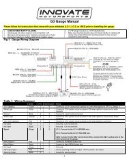
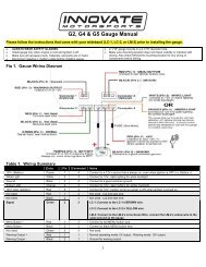
2.1 Main <strong>Gauge</strong> Wiring<br />
1. Connect the RED wire to a switched 12V source. A switched 12V source comes ON as soon<br />
as the ignition on the car is keyed on. Make sure the connection is fused with a minimum<br />
fuse size of 2A.<br />
- 3 -
Circuits that share power with the vehicle’s stereo, ignition system, and fuel pump<br />
are not recommended.<br />
2. Connect the main BLACK wire to a ground source. Note that there are other black wires<br />
coming out of the 2 pin and 3 pin connectors, these are not the main gauge grounds. Avoid<br />
noisy ground sources, such as grounds used for the radio and or ignition.<br />
3. Connect the WHITE wire to a headlight power wire (a wire that supplies current when the<br />
headlights are on). This enables the display to dim for better nighttime viewing. DO NOT<br />
CONNECT THIS WIRE TO THE HEADLIGHT DIMMING WIRE. Connection to this rheostat<br />
type of switch will cause the gauge to malfunction. If you chose not to utilize the dimming<br />
feature, connect this WHITE wire to ground.<br />
2.2 MAP sensor wiring<br />
1 Fish the MAP sensor’s three pin connector through the firewall and to the <strong>MTX</strong> <strong>Boost</strong>/<strong>Shift</strong><br />
gauge.<br />
2 Connect the sensor’s male three pin connector to the female 3 pin connector on the gauge.<br />
3 Coming out of the female three pin connector you will find a black wire with a stripped end.<br />
Connect this black wire to the same ground source as the gauge.<br />
2.3 Tach signal wiring<br />
1. The two pin connector with a red wire is the tach input for the shift light. A tach signal can<br />
be acquired from the negative lead of a coil, ECU, negative lead of an injector, or ignition<br />
box (i.e. MSD 6AL). Connect the tach signal to the red wire of the 2 pin connector<br />
extending the wire as needed.<br />
Note: Ignitions running a multi-spark setup (i.e. MSD 6AL) must use the provided tach signal<br />
from the ignition box.<br />
A tach signal can not be acquired from the negative lead of the coil on vehicles<br />
with CDI ignitions. For these applications use the negative lead of an injector or a tach<br />
adapter (if available for your model ignition).<br />
2. Connect the sensor’s male two pin connector to the female two pin connector on the<br />
gauge.<br />
3. Coming out of the female two pin connector you will find a black wire with a stripped end.<br />
Do not use this wire, isolate and tuck it away.<br />
3 Programming the <strong>Gauge</strong> (LM Programmer)<br />
The <strong>MTX</strong> <strong>Boost</strong>/<strong>Shift</strong> gauge is programmable with the following functionality:<br />
1. Change the display unit of measure from Imperial to Metric<br />
2. Configure the RPM pulses per rotation<br />
3. Setup alarms and warnings<br />
4. Setup shift light modes/parameters<br />
5. Upgrade the firmware<br />
- 4 -
Avoid connecting or disconnecting any of the ports labeled IN or OUT while<br />
the unit is powered ON.<br />
3.1 Installing the LM Programmer Software<br />
Put the included CD in your CD-drive on your computer and follow the instructions on screen.<br />
The installer includes LogWorks, LM Programmer, manuals, and other tools.<br />
3.2 Hooking up the <strong>MTX</strong> <strong>Boost</strong>/<strong>Shift</strong> gauge to the computer<br />
1. Power OFF the <strong>MTX</strong> <strong>Boost</strong>/<strong>Shift</strong> gauge<br />
2. Connect the supplied serial cable to the port labeled OUT.<br />
3. There should be nothing connected to the port labeled IN.<br />
4. Power ON the <strong>MTX</strong> <strong>Boost</strong>/<strong>Shift</strong> gauge.<br />
5. Connect the serial cable to your computer. If you are using a serial to USB adapter,<br />
connect the serial cable to the adapter then connect the adapter to the computer.<br />
6. Launch LM Programmer. The LM Programmer application can be launched from Start-<br />
>Programs->LogWorks3->LM Programmer from the Windows task bar.<br />
3.3 Programming the <strong>Gauge</strong><br />
Whenever a change is made to the programming of the gauge click the Program button for the<br />
change to take effect. Once the gauge has been programmed the Program button will grey out.<br />
To set the gauge back to the factory settings click the Set To Defaults button and then click the<br />
Program button.<br />
- 5 -
3.4 Pressure Tab<br />
1. Display In allows the gauge to display <strong>Boost</strong> in either Imperial or Metric units of<br />
measure.<br />
2. The Overboost Warning will enable the gauge’s seven segment display to flash when<br />
the entered threshold value has been exceeded. To enable this feature the “Enable”<br />
option must be checked.<br />
- 6 -
3.5 RPM Tab<br />
1. Mode: Select how many pulses per rotation based on your tach signal source<br />
2. Scale: Select the RPM scale. Options are 10230 RPM or 20460 RPM. Selected 20460<br />
RPM if your engine rev passed 10230 RPM.<br />
3.6 Display Tab<br />
- 7 -
1. Needle Bar RPM Config: You are able to select between Single Stage or Progressive<br />
shift light.<br />
Single Stage allows the gauge’s outer LEDs to flash each individual LED color segment<br />
or all at a specific threshold. While Single Stage is selected, <strong>Boost</strong> Trace is enabled.<br />
Progressive allows the gauge’s outer LEDs to flash incrementally. <strong>Boost</strong> Trace is<br />
disabled when the Progressive shift light is enabled.<br />
2. Single Stage <strong>Shift</strong> Light: Allows the configuration of either Green, Yellow, Red, or All<br />
LED segments to flash at the desired shift threshold. This selection is enabled when<br />
Single Stage is selected in Needle Bar RPM Config.<br />
3. Progressive <strong>Shift</strong> Light: Allows the configuration of the progressive shift light at each<br />
outer LED segment. This selection is enabled when Progressive is selected in Needle<br />
Bar RPM Config.<br />
4. <strong>Boost</strong> Trace: Allows the configuration of the progressive shift light at each outer LED<br />
segment. <strong>Boost</strong> Trace is enabled when Single Stage is selected. In addition to the Single<br />
Stage shift light a single LED (virtual needle) will be illuminated indicating the boost level.<br />
The <strong>Boost</strong> range displayed is user defined.<br />
3.7 Updating the Firmware<br />
The LM Programmer Info tab reports the firmware <strong>version</strong> currently installed on your unit. Do not<br />
update the firmware if the <strong>version</strong>s are the same. A firmware update should only be<br />
necessary if there has been a new release that specifically fixes a problem that you are<br />
experiencing with the unit.<br />
Firmware for the <strong>MTX</strong> <strong>Boost</strong>/<strong>Shift</strong> gauge has the extension dld. New firmware releases are<br />
available for download on the <strong>Innovate</strong> <strong>Motorsports</strong>’ web site (www.tuneyourengine.com) under<br />
‘Support.’<br />
1. Power OFF the <strong>MTX</strong> <strong>Boost</strong>/<strong>Shift</strong> gauge<br />
2. Connect the supplied serial cable to the port labeled OUT.<br />
3. There should be nothing connected to the port labeled IN.<br />
4. Power ON the <strong>MTX</strong> <strong>Boost</strong>/<strong>Shift</strong> gauge.<br />
5. Connect the serial cable to your computer. If you are using a serial to USB adapter,<br />
connect the serial cable to the adapter then connect the adapter to the computer.<br />
6. Launch LM Programmer. The LM Programmer application can be launched from Start-<br />
>Programs->LogWorks3->LM Programmer from the Windows task bar.<br />
7. Once connected the LM Programmer will display the current <strong>version</strong> of the firmware that<br />
is installed in the LM-2. Do not update the firmware if the <strong>version</strong>s are the same. A<br />
firmware update should only be necessary if there has been a new release.<br />
8. On the very first tab of LM Programmer you will see a button labeled “Update Firmware,”<br />
click this button.<br />
9. Select the firmware file with the dld extension.<br />
10. Do not disconnect the unit from the computer until the firmware progress screen<br />
completely disappears. Once finished you may disconnect the unit from the computer<br />
and exit out of the software.<br />
If your computer crashes during a firmware upgrade, the <strong>MTX</strong> <strong>Boost</strong>/<strong>Shift</strong> gauge has a recovery<br />
mechanism where it will be able to retry the download again and not be disabled by half loaded<br />
firmware. Switch the <strong>MTX</strong> <strong>Boost</strong>/<strong>Shift</strong> gauge off and on again and then reload LM Programmer.<br />
The recovery mechanism is designed to be able to recover 99.9% of the time. While we don’t<br />
- 8 -
anticipate this occurring, it is possible that the <strong>MTX</strong> will not recover correctly and may need to be<br />
serviced at our factory. If you suspect this is the case, contact <strong>Innovate</strong> support.<br />
4 LogWorks<br />
The <strong>MTX</strong> <strong>Boost</strong>/<strong>Shift</strong> gauge can be connected to the LogWorks software to record and analyze<br />
boost and engine RPM. The gauge can also be connected to other <strong>Innovate</strong> <strong>Motorsports</strong><br />
products to create a log chain with additional gauges and sensors.<br />
4.1 Connecting the <strong>MTX</strong> <strong>Boost</strong>/<strong>Shift</strong> gauge to other MTS products<br />
The <strong>MTX</strong> <strong>Boost</strong>/<strong>Shift</strong> gauge has a port labeled IN and a port labeled OUT. These connections<br />
allow multiple MTS (Modular Tuning System) devices to be connected together in order to form a<br />
single log chain.<br />
There are two types of cables used to interface the <strong>MTX</strong> <strong>Boost</strong>/<strong>Shift</strong> gauge. The 3812 cable is a 4<br />
pin micro fit to 2.5mm male stereo plug used. The 3846 cable is a 4pin Micro fit to 4pin Micro fit.<br />
These cables are sold separately, make sure to select the correct cables to interface the product<br />
you own.<br />
1. Power OFF all your MTS devices.<br />
2. Start with the first product in the serial chain. Using the appropriate mating cable,<br />
connect the OUT port from the first device and feed it into the IN port of the second<br />
device. (Note: If you have an LC-1, there must be a terminator plug in the serial IN if it is<br />
the first device in the serial chain.)<br />
3. Continue connecting the OUT port of each device into the IN until all your devices are<br />
connected together.<br />
4. If a recording device is not connected to the serial chain, e.g. DL-32, LM-2, the OUT<br />
port of the last device can be connected directly to a computer to log with the LogWorks<br />
software<br />
5. Once all the connections of the ports labeled IN and OUT are made the MTS devices<br />
can be powered ON.<br />
4.2 Logging data<br />
1. Power OFF the <strong>MTX</strong> <strong>Boost</strong>/<strong>Shift</strong> gauge<br />
2. Connect the supplied serial cable to the port labeled OUT.<br />
3. There should be nothing connected to the port labeled IN.<br />
4. Power ON the <strong>MTX</strong> <strong>Boost</strong>/<strong>Shift</strong> gauge.<br />
5. Connect the serial cable to your computer. If you are using a serial to USB adapter,<br />
connect the serial cable to the adapter then connect the adapter to the computer.<br />
6. Launch LogWorks. The LogWorks application can be launched from Start->Programs-<br />
>LogWorks3->Logworks3 from the Windows task bar.<br />
7. Once LogWorks launches go to File->Connect. You will be prompted to connect to serial<br />
COM port. Click Connect.<br />
8. To start recording go to File->New Real-time Log or, in the Toolbar, click on the Tool.<br />
- 9 -
5 Changing the <strong>MTX</strong> gauge face and/or bezel<br />
1. Lay the <strong>MTX</strong> gauge face down and remove the three #2 phillips screws from the outside<br />
rim of the back plate.<br />
2. Carefully lift off the bezel from the gauge cup.<br />
3. Configure the gauge as desired by changing the gauge face and or bezel.<br />
*Be sure to remove protective film from the gauge face. This can be done easily<br />
with a piece of scotch tape.<br />
4. Make sure every piece is positioned correctly using the locating tab and reassemble the<br />
gauge.<br />
5. Reinstall the 3 #2 phillips screws.<br />
- 10 -
Appendix A: Limited Warranty<br />
LIMITED WARRANTY<br />
<strong>Innovate</strong> stands behind the quality of its products. <strong>Innovate</strong> makes the following warranty to<br />
purchasers of its products: All new <strong>Innovate</strong> products carry a one year warranty from the date of<br />
purchase. If proof of purchase cannot be provided, warranty will be determined by date of<br />
manufacture.<br />
When Warranty Void<br />
This warranty shall terminate and <strong>Innovate</strong> shall have no obligation pursuant to it if (i) your<br />
<strong>Innovate</strong> product has been modified or repaired in a manner not previously authorized by<br />
<strong>Innovate</strong> in writing, (ii) the identification markings on your <strong>Innovate</strong> product have been removed,<br />
defaced, or altered; (iii) your <strong>Innovate</strong> product was subjected to accident, abuse, shipping<br />
damage, or improper use; (iv) your <strong>Innovate</strong> product was not used or configured as specified in<br />
the product manual; or (v) your <strong>Innovate</strong> product was subjected to operating conditions more<br />
severe than those specified in the product manual.<br />
Exclusions From This Warranty<br />
Oxygen Sensors are excluded from this warranty.<br />
Repairs Under This Warranty<br />
In the unlikely event that your <strong>Innovate</strong> hardware product should prove defective during the<br />
warranty period, contact <strong>Innovate</strong> Customer Support for a return material authorization (RMA) at<br />
(800) 348 3037. Products returned for service must be securely packed to prevent damage and<br />
shipped charges pre paid, along with proof of purchase and the return material authorization<br />
form, to the <strong>Innovate</strong> repair location as instructed by Customer Service. <strong>Innovate</strong> within a<br />
reasonable amount of time from its receipt of your product so shipped, will ship to you, at its<br />
option, the repaired product or a new or reconditioned product of comparable or greater specified<br />
functionality. All repaired or replacement products shall be warranted for the remainder of the<br />
original product warranty.<br />
Disclaimer<br />
INNOVATE MAKES NO OTHER EXPRESS OR IMPLIED WARRANTY WITH RESPECT TO<br />
YOUR INNOVATE PRODUCT OTHER THAN THE LIMITED WARRANTY SET FORTH ABOVE.<br />
No <strong>Innovate</strong> dealer, agent, or employee is authorized to make any modification, extension, or<br />
addition to this warranty, unless enforceable or unlawful under applicable law, INNOVATE<br />
DISCLAIMS ALL IMPLIED WARRANTIES, INCLUDING THE IMPLIED WARRANTIES OF<br />
MERCHANTABILITY, NONINFRINGEMENT, AND FITNESS FOR A PARTICULAR PURPOSE,<br />
AND THE LIABILITY OF INNOVATE, IF ANY, FOR DAMAGES RELATING TO ANY<br />
ALLEGEDLY DEFECTIVE PRODUCT SHALL UNDER ANY TORT, CONTRACT, OR OTHER<br />
LEGAL THEORY BE LIMITED TO THE ACTUAL PRICE PAID FOR SUCH PRODUCT AND<br />
SHALL IN NO EVENT INCLUDE INCIDENTAL, CONSEQUENTIAL, SPECIAL, OR INDIRECT<br />
DAMAGES OF ANY KIND EVEN IF INNOVATE IS AWARE OF THE POSSIBILITY OF SUCH<br />
DAMAGES. Some states do not allow limitations on how long an implied warranty lasts or the<br />
exclusion or limitation of incidental or consequential damages, so the above limitations or<br />
exclusions may not apply to you.<br />
- 11 -
Revision History<br />
1.0 – 4/5/2012<br />
Initial release.<br />
<strong>1.1</strong> – 5/4/2012<br />
Added addition screen shots and wiring diagram<br />
- 12 -