Rated Power and VSWR Improvement of Termination Resistor with ...
Rated Power and VSWR Improvement of Termination Resistor with ...
Rated Power and VSWR Improvement of Termination Resistor with ...

You also want an ePaper? Increase the reach of your titles
YUMPU automatically turns print PDFs into web optimized ePapers that Google loves.
levels by making good use <strong>of</strong> the relatively larger area <strong>of</strong> the circuit board to dissipate the<br />
heat.<br />
We explored the ways to improve heat transfer through the footprint. We established a low<br />
thermal resistance interface from the resistive element to the circuit board. We maximized<br />
the termination electrode’s size. Therefore heat has more ways to transfer from the surface to<br />
the circuit board. We also used high purity, high thermal conductivity chip carrier to further<br />
lower the thermal resistivity. We also investigated special design consideration, to ensure a<br />
balanced distribution <strong>of</strong> the generated heat.<br />
Improve heat transfer rate:<br />
We studied to improve the heat transfer rate through the component footprint. We realized<br />
that the faster the heat can transfer from the electrodes, the less time the heat has to keep the<br />
electrodes hot. If the heat cannot move faster through the electrodes <strong>and</strong> more heat is<br />
generating in the chip resistor, then the electrodes keep getting hotter. As the temperature<br />
rise, at some point the surface temperature could exceed the melting point <strong>of</strong> the mounting<br />
solder <strong>and</strong> potentially makes a crack in the solder joint. This phenomenon can potentially<br />
cause irreversible changes in resistance – as well as potential damage to the printed circuit<br />
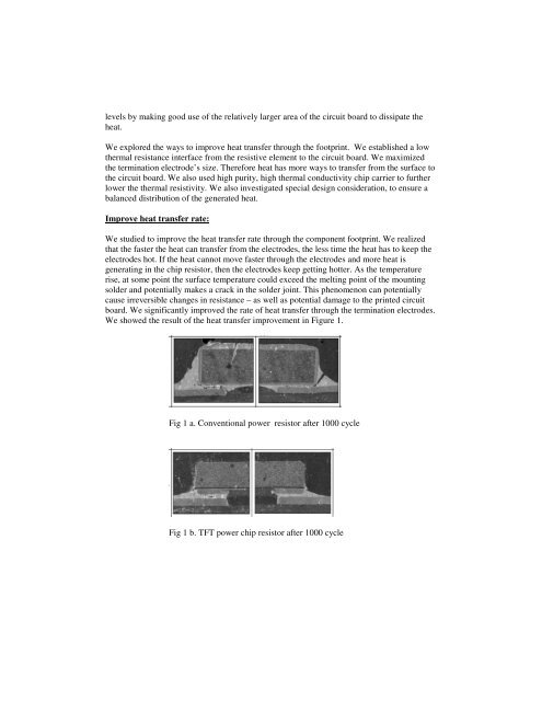
board. We significantly improved the rate <strong>of</strong> heat transfer through the termination electrodes.<br />
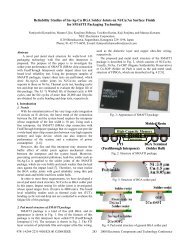
We showed the result <strong>of</strong> the heat transfer improvement in Figure 1.<br />
Fig 1 a. Conventional power resistor after 1000 cycle<br />
Fig 1 b. TFT power chip resistor after 1000 cycle