13 HP, 30 GallON air cOmPressOr - Harbor Freight Tools
13 HP, 30 GallON air cOmPressOr - Harbor Freight Tools
13 HP, 30 GallON air cOmPressOr - Harbor Freight Tools

You also want an ePaper? Increase the reach of your titles
YUMPU automatically turns print PDFs into web optimized ePapers that Google loves.
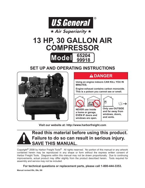
<strong>13</strong> <strong>HP</strong>, <strong>30</strong> GalLON Air<br />
compressor<br />
65204<br />
99918<br />
Set up and Operating Instructions<br />
Using an engine indoors CAN KILL YOU IN<br />
MINUTES.<br />
Engine exhaust contains carbon monoxide.<br />
This is a poison you cannot see or smell.<br />
<br />
NEVER use inside<br />
a home or garage,<br />
EVEN IF doors and<br />
windows are open.<br />
Visit our website at: http://www.harborfreight.com<br />
Only use OUTSIDE<br />
and far away from<br />
windows, doors,<br />
and vents.<br />
Read this material before using this product.<br />
Failure to do so can result in serious injury.<br />
Save this manual.<br />
Copyright © 2008 by <strong>Harbor</strong> <strong>Freight</strong> <strong>Tools</strong> ® . All rights reserved. No portion of this manual or any artwork<br />
contained herein may be reproduced in any shape or form without the express written consent of<br />
<strong>Harbor</strong> <strong>Freight</strong> <strong>Tools</strong>. Diagrams within this manual may not be drawn proportionally. Due to continuing<br />
improvements, actual product may differ slightly from the product described herein. <strong>Tools</strong> required for<br />
assembly and service may not be included.<br />
For technical questions or replacement parts, please call 1-800-444-3353.<br />
Manual revised 09c, 09e, 09i
Contents<br />
Important SAFETY<br />
Information ............................ 3<br />
Basic Specifications ............. 8<br />
Components and Controls8<br />
Equipment Set Up .................... 9<br />
Unpacking .......................................9<br />
Mounting .........................................9<br />
Equipment Oil Fill .......................9<br />
Operating Instructions .... 10<br />
Work Piece and Work Area<br />
Set Up ..........................................10<br />
General Operating<br />
Instructions ............................10<br />
User-Maintenance<br />
Instructions ........................ 12<br />
Cleaning, Maintenance, and<br />
Lubrication ...............................12<br />
Daily ..........................................12<br />
Weekly ......................................12<br />
Monthly ...................................12<br />
Troubleshooting ......................14<br />
PARTS Lists .............................. 16<br />
Main ASSEMBLY DIAGRAM ...... 17<br />
Pump ASSEMBLY DIAGRAM ..... 18<br />
Limited 1 year / 90 day<br />
Warranty .............................. 19<br />
SKU 65204/<br />
99918<br />
For technical questions, please call 1-800-444-3353.<br />
Page 2
Save This Manual<br />
Keep this manual for the safety warnings<br />
and precautions, assembly, operating,<br />
inspection, maintenance and cleaning<br />
procedures. Write the product’s serial<br />
number in the back of the manual near the<br />
assembly diagram (or month and year of<br />
purchase if product has no number). Keep<br />
this manual and the receipt in a safe and<br />
dry place for future reference.<br />
Important SAFETY<br />
Information<br />
In this manual, on the labeling,<br />
and all other information<br />
provided with this product:<br />
This is the safety alert<br />
symbol. It is used to alert<br />
you to potential personal<br />
injury hazards. Obey all<br />
safety messages that<br />
follow this symbol to avoid<br />
possible injury or death.<br />
DANGER indicates<br />
a hazardous<br />
situation which, if not<br />
avoided, will result in death or<br />
serious injury.<br />
WARNING<br />
indicates a<br />
hazardous situation which, if<br />
not avoided, could result in<br />
death or serious injury.<br />
CAUTION, used<br />
with the safety<br />
alert symbol, indicates a<br />
hazardous situation which, if<br />
not avoided, could result in<br />
minor or moderate injury.<br />
1.<br />
2.<br />
3.<br />
4.<br />
NOTICE is used to<br />
address practices<br />
not related to personal injury.<br />
CAUTION, without<br />
the safety alert<br />
symbol, is used to address<br />
practices not related to<br />
personal injury.<br />
WARNING! Read all instructions.<br />
Failure to follow all instructions<br />
listed below may result in fire,<br />
serious injury and/or DEATH.<br />
The warnings and precautions<br />
discussed in this manual cannot<br />
cover all possible conditions and<br />
situations that may occur. It must<br />
be understood by the operator that<br />
common sense and caution are<br />
factors which cannot be built into<br />
this product, but must be supplied<br />
by the operator.<br />
SAVE THESE INSTRUCTIONS<br />
Set up precautions<br />
Gasoline fuel and fumes are flammable,<br />
and potentially explosive. Use<br />
proper fuel storage and handling procedures.<br />
Do not store fuel or other<br />
flammable materials nearby.<br />
Have multiple ABC class fire extinguishers<br />
nearby.<br />
Operation of this equipment may create<br />
sparks that can start fires around<br />
dry vegetation.<br />
A spark arrestor may be required.<br />
The operator should contact local fire<br />
agencies for laws or regulations relating<br />
to fire prevention requirements.<br />
Set up and use only on a flat, level,<br />
well-ventilated surface.<br />
SKU 65204/<br />
99918<br />
For technical questions, please call 1-800-444-3353.<br />
Page 3
5.<br />
6.<br />
Wear ANSI-approved safety goggles<br />
and heavy-duty work gloves during<br />
set up.<br />
Use only lubricants and fuel recommended<br />
in the engine manual or in<br />
the Specifications chart of this manual.<br />
3.<br />
4.<br />
Do not leave the equipment unattended<br />
when it is running. Turn off<br />
the equipment (and remove safety<br />
keys, if available) before leaving the<br />
work area.<br />
Wear ANSI-approved safety glasses<br />
and hearing protection during use.<br />
Engine precautions<br />
Follow engine precautions and instructions<br />
in the included engine<br />
instruction manual.<br />
Operating precautions<br />
1. Carbon Monoxide<br />
Hazard<br />
Using an engine indoors<br />
CAN KILL YOU IN<br />
MINUTES.<br />
Engine exhaust contains carbon<br />
monoxide. This is a poison you<br />
cannot see or smell.<br />
NEVER use inside a home or garage,<br />
EVEN IF doors and windows are<br />
open.<br />
5.<br />
6.<br />
7.<br />
8.<br />
People with pacemakers should<br />
consult their physician(s) before<br />
use. Electromagnetic fields in close<br />
proximity to a heart pacemaker could<br />
cause pacemaker interference or<br />
pacemaker failure. Caution is necessary<br />
when near the engine’s magneto<br />
or recoil starter.<br />
Use only accessories that are recommended<br />
by <strong>Harbor</strong> <strong>Freight</strong> <strong>Tools</strong> for<br />
your model. Accessories that may be<br />
suitable for one piece of equipment<br />
may become hazardous when used<br />
on another piece of equipment.<br />
Do not operate in explosive atmospheres,<br />
such as in the presence of<br />
flammable liquids, gases, or dust.<br />
Gasoline-powered engines may ignite<br />
the dust or fumes.<br />
Stay alert, watch what you are doing<br />
and use common sense when operating<br />
this piece of equipment. Do not<br />
use this piece of equipment while<br />
tired or under the influence of drugs,<br />
alcohol or medication.<br />
2.<br />
Only use OUTSIDE and far away<br />
from windows, doors, and vents.<br />
Keep children away from the equipment,<br />
especially while it is operating.<br />
SKU 65204/<br />
99918<br />
Do not overreach. Keep proper footing<br />
and balance at all times. This enables<br />
better control of the equipment<br />
in unexpected situations.<br />
For technical questions, please call 1-800-444-3353.<br />
9.<br />
10.<br />
Dress properly. Do not wear loose<br />
clothing or jewelry. Keep h<strong>air</strong>, clothing<br />
and gloves away from moving<br />
parts. Loose clothes, jewelry or long<br />
h<strong>air</strong> can be caught in moving parts.<br />
Page 4
11.<br />
12.<br />
<strong>13</strong>.<br />
14.<br />
15.<br />
16.<br />
17.<br />
18.<br />
19.<br />
Parts, especially exhaust system<br />
components, get very hot during use.<br />
Stay clear of hot parts.<br />
Do not cover the engine or equipment<br />
during operation.<br />
Keep the equipment, engine, and surrounding<br />
area clean at all times.<br />
Use the equipment, accessories, etc.,<br />
in accordance with these instructions<br />
and in the manner intended for the<br />
particular type of equipment, taking<br />
into account the working conditions<br />
and the work to be performed. Use<br />
of the equipment for operations different<br />
from those intended could result<br />
in a hazardous situation.<br />
Do not operate the equipment with<br />
known leaks in the engine’s fuel system.<br />
This product contains or, when used,<br />
produces a chemical known to the<br />
State of California to cause cancer<br />
and birth defects or other reproductive<br />
harm. (California Health & Safety<br />
Code § 25249.5, et seq.)<br />
When spills of fuel or oil occur, they<br />
must be cleaned up immediately.<br />
Dispose of fluids and cleaning materials<br />
as per any local, state, or federal<br />
codes and regulations. Store oil rags<br />
in a bottom-ventilated, covered, metal<br />
container.<br />
Keep hands and feet away from<br />
moving parts. Do not reach over or<br />
across equipment while operating.<br />
Before use, check for misalignment<br />
or binding of moving parts, breakage<br />
of parts, and any other condition that<br />
may affect the equipment’s operation.<br />
If damaged, have the equipment<br />
20.<br />
1.<br />
2.<br />
3.<br />
4.<br />
5.<br />
serviced before using. Many accidents<br />
are caused by poorly maintained<br />
equipment.<br />
Use the correct equipment for the<br />
application. Do not modify the equipment<br />
and do not use the equipment<br />
for a purpose for which it is not intended.<br />
Service precautions<br />
Before service, maintenance, or<br />
cleaning:<br />
a. Turn the engine switch to its<br />
“OFF” position.<br />
b. Allow the engine to completely<br />
cool.<br />
c. Then, remove the spark plug<br />
wire(s) from the spark plug(s).<br />
Keep all safety guards in place and in<br />
proper working order. Safety guards<br />
include the belt guard, muffler, <strong>air</strong><br />
cleaner, mechanical guards, and heat<br />
shields, among other guards.<br />
Do not alter or adjust any part of<br />
the equipment or its engine that is<br />
sealed by the manufacturer or distributor.<br />
Only a qualified service<br />
technician may adjust parts that<br />
may increase or decrease governed<br />
engine speed.<br />
Wear ANSI-approved safety goggles,<br />
heavy-duty work gloves, and dust<br />
mask/respirator during service.<br />
Maintain labels and nameplates on<br />
the equipment. These carry important<br />
information. If unreadable or<br />
missing, contact <strong>Harbor</strong> <strong>Freight</strong> <strong>Tools</strong><br />
for a replacement.<br />
SKU 65204/<br />
99918<br />
For technical questions, please call 1-800-444-3353.<br />
Page 5
6.<br />
7.<br />
8.<br />
9.<br />
10.<br />
Have the equipment serviced by a<br />
qualified rep<strong>air</strong> person using only<br />
identical replacement parts. This will<br />
ensure that the safety of the equipment<br />
is maintained. Do not attempt<br />
any service or maintenance procedures<br />
not explained in this manual<br />
or any procedures that you are uncertain<br />
about your ability to perform<br />
safely or correctly.<br />
Store equipment out of the reach of<br />
children.<br />
Follow scheduled engine and equipment<br />
maintenance.<br />
Tanks rust from moisture build-up,<br />
weakening the tank. Drain tank daily<br />
and inspect periodically.<br />
Do not remove or adjust safety valve.<br />
11.<br />
Refueling:<br />
a. Do not smoke, or allow sparks,<br />
flames, or other sources of ignition<br />
around the equipment, especially<br />
when refuelling.<br />
b. Do not refill the fuel tank while the<br />
engine is running or hot.<br />
c. Do not fill fuel tank to the top. Leave<br />
a little room for the fuel to expand as<br />
needed.<br />
d. Refuel in a well-ventilated area only.<br />
Save these<br />
instructions.<br />
SKU 65204/<br />
99918<br />
For technical questions, please call 1-800-444-3353.<br />
Page 6
This page intentionally<br />
left blank<br />
SKU 65204/<br />
99918<br />
For technical questions, please call 1-800-444-3353.<br />
Page 7
Basic Specifications<br />
Equipment<br />
Lubricant<br />
Engine<br />
Type<br />
Capacity<br />
Rotation viewed from PTO<br />
(power takeoff - the output shaft)<br />
Engine Shaft<br />
Air Pressure Range<br />
Air Outlet<br />
Air Flow<br />
Engine Idle Speed<br />
Compressor Oil<br />
1.37 Quarts<br />
65204<br />
<strong>13</strong> <strong>HP</strong>, EPA/CARB<br />
Compliant<br />
99918 <strong>13</strong> <strong>HP</strong>, EPA Compliant<br />
Counterclockwise<br />
Ø 1” x 2- 7 / 8 ” Long<br />
1 / 4 ” Keyway<br />
3 / 8 ”-24 UNF inner thread<br />
145-175 PSI<br />
3/4" NPT<br />
19.5 CFM @ 40 PSI<br />
18.7 CFM @ 100 PSI<br />
1,800±100 RPM<br />
(Pressure switch controlled)<br />
Note: Engine specifications are found in<br />
the engine manual supplied with this<br />
equipment.<br />
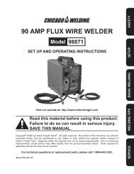
Components and<br />
Controls<br />
Belt Guard<br />
Air<br />
Filter<br />
Oil<br />
Sight<br />
Glass<br />
2.<br />
3.<br />
4.<br />
5.<br />
6.<br />
1. Belt Guard. The Belt Guard (A1)<br />
encloses the pulleys and drive belts.<br />
It protects the user from the moving<br />
parts and allows the large pulley<br />
to direct cooling <strong>air</strong> to the Air Pump<br />
(A2).<br />
Oil Sight Glass. The oil sight glass<br />
shows proper level of the oil. Oil level<br />
should be at center of Sight Glass.<br />
Tank Drain Valve. The Air Tank (A18)<br />
drain valve allows moisture to be<br />
removed from the tank to reduce the<br />
chance of corrosion inside the tank.<br />
Safety Valve. This Safety Valve (A15)<br />
automatically releases <strong>air</strong> if the Air<br />
Tank (A18) pressure exceeds the<br />
preset maximum.<br />
a. In an emergency, the ring could be<br />
pulled to reduce tank <strong>air</strong> pressure.<br />
Ball Valve. Air hose attaches to this<br />
valve. Air pressure required by tools<br />
is set by an <strong>air</strong> pressure regulator.<br />
Regulator and Gauge (Not Included).<br />
Outlet <strong>air</strong> can be regulated by adjusting<br />
the regulator knob. Clockwise will<br />
raise outlet pressure and counterclockwise<br />
will lower outlet pressure.<br />
Outlet pressure will be displayed on<br />
the regulator’s pressure gauge.<br />
Air Storage Tank. The Air Tank (A18)<br />
is where <strong>air</strong> pressurized by the Air<br />
Pump (A2) is stored for later use.<br />
Ball<br />
Valve<br />
Pilot<br />
Valve<br />
Safety<br />
Valve<br />
Tank Pressure<br />
Gauge<br />
7.<br />
Tank Pressure Gauge. The Air Tank<br />
Pressure Gauge (A20) displays the<br />
<strong>air</strong> pressure in the tank.<br />
Tank Drain<br />
Air Storage Tank<br />
Fig. 1<br />
SKU 65204/<br />
99918<br />
For technical questions, please call 1-800-444-3353.<br />
Page 8
Pilot<br />
Valve<br />
1.<br />
2.<br />
Mounting<br />
The compressor may vibrate strongly<br />
during use, so mounting is needed to<br />
prevent movement.<br />
Before use, mount the compressor<br />
securely using all four mounting holes<br />
to a solid, level surface, such as a<br />
concrete slab or truck bed.<br />
8. Pilot Valve. Open the Pilot Valve<br />
before starting the engine. It relieves<br />
resistance on the engine to make<br />
starting easier. It is shown in the<br />
open position above. Push the pin<br />
over to one side to close it.<br />
Equipment Set Up<br />
Read the entire Important<br />
Safety Information<br />
section at the beginning of this<br />
manual including all text under<br />
subheadings therein before set<br />
up or use of this product.<br />
Note: For additional information regarding<br />
the parts listed in the following pages,<br />
refer to the Assembly Diagrams near<br />
the end of this manual.<br />
Unpacking<br />
Note: Do not use the <strong>air</strong> cleaner to lift or<br />
move the compressor. It is not designed<br />
to withstand such force.<br />
3.<br />
Rubber pads (not included) may be<br />
used at the mounting points to reduce<br />
vibration.<br />
Equipment Oil Fill<br />
IMPORTANT. To prevent property<br />
damage and voiding of the<br />
warranty:<br />
Before first use, fill the compressor<br />
with compressor oil as follows:<br />
1.<br />
2.<br />
3.<br />
Remove the Breather Vent (22) and<br />
fill with 1.37 quarts of premium quality<br />
SAE <strong>30</strong>-weight, non-detergent, synthetic<br />
<strong>air</strong> compressor oil. Do not mix<br />
oils of different types.<br />
Check the oil level at the Oil Sight<br />
Glass. The oil level should be at the<br />
middle of the Glass. Add or drain<br />
oil as needed until it is at the proper<br />
level.<br />
Thread the Breather Vent (22) back<br />
into place, being careful not to crossthread<br />
it or strip its threads.<br />
When unpacking, make sure that the<br />
item is intact and undamaged. If any parts<br />
are missing or broken, please call <strong>Harbor</strong><br />
<strong>Freight</strong> <strong>Tools</strong> at 1-800-444-3353 as soon<br />
as possible.<br />
REV 09c<br />
SKU 65204/<br />
99918<br />
For technical questions, please call 1-800-444-3353.<br />
Page 9
Operating Instructions<br />
Read the entire Important<br />
Safety Information<br />
section at the beginning of this<br />
manual including all text under<br />
subheadings therein before set<br />
up or use of this product.<br />
Inspect compressor before<br />
use, looking for damaged,<br />
loose, and missing parts. If any<br />
problems are found, do not use<br />
until rep<strong>air</strong>ed.<br />
Work Piece and Work Area Set Up<br />
1.<br />
2.<br />
3.<br />
4.<br />
The Compressor’s engine runs on<br />
gasoline and must be set up in an<br />
area free from ignition sources.<br />
Do not set up too close to a wall or<br />
in a confined area. The Air Pump<br />
(A2) and Gas Engine (A4) must have<br />
adequate fresh <strong>air</strong> in order to operate<br />
properly and not overheat.<br />
Designate a work area that is clean<br />
and well-lit. The work area must not<br />
allow access by children or pets to<br />
prevent injury and distraction.<br />
Route the <strong>air</strong> hose along a safe route<br />
to reach the work area without creating<br />
a tripping hazard or exposing the<br />
<strong>air</strong> hose to possible damage. The <strong>air</strong><br />
hose must be long enough to reach<br />
the work area with enough extra<br />
length to allow free movement while<br />
working.<br />
1.<br />
2.<br />
3.<br />
4.<br />
General<br />
Operating Instructions<br />
Before starting the engine:<br />
a. Follow the Set Up<br />
Instructions to prepare the<br />
equipment.<br />
b. Inspect the equipment and<br />
engine.<br />
c. Fill the engine with the<br />
proper amount and type of<br />
both fuel and oil. Note: The<br />
Oil Sensor (if equipped)<br />
will prevent the engine<br />
from operating if the oil is<br />
not up to the proper level.<br />
NOTE: THIS ENGINE<br />
INCLUDES AN AUTOMATIC<br />
LOW OIL SHUTDOWN<br />
SENSOR THAT DISABLES<br />
THE ENGINE IF THE OIL<br />
LEVEL IS TOO LOW.<br />
d. For electric start, make<br />
sure battery is 12 V, 36+<br />
Ah, is fully charged, and is<br />
correctly connected with<br />
proper cables.<br />
Set up <strong>air</strong> system according to <strong>air</strong><br />
tool’s instructions (sold separately).<br />
All lubricated compressor pumps discharge<br />
some condensed water and<br />
oil with the compressed <strong>air</strong>. Components<br />
such as <strong>air</strong> dryers, moisture filters,<br />
regulators, and automatic oilers<br />
may be required.<br />
Open the Fuel Valve.<br />
Close the Choke.<br />
Check the compressor oil level (using<br />
the Oil Sight Glass) and the engine<br />
oil level. Add oil as needed.<br />
REV 09c, 09i<br />
SKU 65204/<br />
99918<br />
5. Empty all <strong>air</strong> pressure from the tank.<br />
For technical questions, please call 1-800-444-3353. Page 10
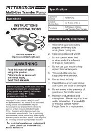
6.<br />
Off<br />
Before starting the engine, open the<br />
Pilot Valve by standing the pin up.<br />
Run<br />
Starter Control Panel<br />
Start<br />
Charging System<br />
Overload Indicator<br />
Note: Moving the Choke too fast could kill<br />
the engine.<br />
7.<br />
IMPORTANT: Allow the engine to run<br />
at no load for five minutes after each<br />
start-up so that the engine can stabilize.<br />
0<br />
S<br />
Ignition Switch<br />
(Close-up)<br />
Ignition<br />
Switch<br />
Charging System<br />
Circuit Protector<br />
7a. To start the engine using the electric<br />
starter:<br />
Insert the ignition key into the ignition.<br />
While turning the key to Start (S<br />
position, max 5 seconds) very slowly<br />
move the choke lever from cold to run<br />
position.<br />
Note: To prolong starter life, use<br />
short starting cycles (5 seconds maximum).<br />
Then wait one minute before<br />
attempting to start again.<br />
5b.<br />
To start the engine manually:<br />
To re-start a warm engine, move the<br />
Choke to halfway closed. Insert the<br />
ignition key into the Ignition and turn<br />
the Key to Run (I position). Grasp<br />
the starter handle, and pull slowly<br />
until resistance is felt. While holding<br />
the handle, allow the starter rope to<br />
rewind slowly. Then, pull the starter<br />
handle with a rapid, full arm stroke.<br />
Once again while holding the handle,<br />
allow the rope to rewind slowly. Repeat<br />
as necessary, until the engine<br />
starts.<br />
0<br />
S<br />
8.<br />
9.<br />
10.<br />
11.<br />
12.<br />
Close the pilot valve after the engine<br />
has started, by laying the pin down.<br />
This allows the compressor to build<br />
up pressure.<br />
When the Gas Engine (A4) is started<br />
and running, the Air Pump (A2) starts<br />
compressing <strong>air</strong> into the Air Tank<br />
(A18) for storage.<br />
When maximum tank pressure is<br />
reached, the compressor automatically<br />
disengages, and the engine<br />
RPM drops down to idle speed. The<br />
engine remains at idle until Air Tank<br />
pressure falls to a preset level. The<br />
Gas Engine will then accelerate and<br />
<strong>air</strong> pressure once again begins to<br />
build up in the Air Tank.<br />
To turn off the engine, turn the key off<br />
(0 position). Close the fuel valve.<br />
Drain the moisture from the tank<br />
daily.<br />
6.<br />
Allow the Engine to run for several<br />
seconds. Then, if the Choke is<br />
closed, open it (move to the run position).<br />
SKU 65204/<br />
99918<br />
For technical questions, please call 1-800-444-3353.<br />
Page 11
User-Maintenance<br />
Instructions<br />
Procedures not specifically<br />
explained in this manual<br />
must be performed only by a<br />
qualified technician.<br />
To prevent<br />
serious injury<br />
from accidental<br />
operation:<br />
Disconnect spark plug and<br />
release all <strong>air</strong> pressure before<br />
maintenance.<br />
To prevent serious<br />
injury from tool<br />
failure:<br />
Do not use damaged<br />
equipment. If abnormal noise,<br />
vibration, or leaking <strong>air</strong><br />
occurs, have the problem<br />
corrected before further use.<br />
To prevent serious<br />
injury:<br />
Do not adjust or tamper with<br />
any control or component in a<br />
way not specifically explained<br />
within this manual. Improper<br />
adjustment can result in tool<br />
failure or other serious<br />
hazards.<br />
Cleaning, Maintenance, and<br />
Lubrication<br />
Note: These procedures are in addition to<br />
the regular checks and maintenance<br />
explained as part of the regular operation<br />
of the <strong>air</strong>-operated tool.<br />
Daily<br />
1.<br />
2.<br />
3.<br />
Weekly<br />
1.<br />
2.<br />
3.<br />
Check compressor oil level at sight<br />
glass. Add premium quality SAE<br />
<strong>30</strong>-weight, non-detergent, synthetic<br />
<strong>air</strong> compressor oil as needed. Do not<br />
mix oils of different types.<br />
Check engine oil level. Add oil as<br />
needed according to engine manual’s<br />
instructions.<br />
Drain moisture from tank.<br />
Inspect <strong>air</strong> pump’s Air Filter (67). Replace<br />
if necessary. To replace:<br />
a. Unscrew the wing nut holding the<br />
filter cover.<br />
b. Remove the filter cover.<br />
c. Remove the filter element and replace<br />
with a new one.<br />
d. Slide the filter cover back over the<br />
filter element and screw the wing nut<br />
back on and tighten securely.<br />
Monthly<br />
1.<br />
Check safety valve by pulling and releasing<br />
ring. Valve should seal once<br />
released.<br />
Clean excessive dirt/dust from unit.<br />
Check and adjust belt tension according<br />
to the steps below:<br />
Remove the belt cover and set it<br />
aside.<br />
SKU 65204/<br />
99918<br />
For technical questions, please call 1-800-444-3353.<br />
Page 12
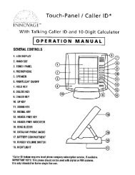
Deflection<br />
Distance<br />
2. Press on the center of the longest<br />
span on each belt with moderate<br />
finger pressure (4-4.5 lb.). Then<br />
measure the deflection distance, the<br />
distance that the belt moved. The<br />
belt should deflect anywhere from<br />
1/4” to 1/2”.<br />
Engine Mounting Bolts<br />
3. If the belts deflect too much,<br />
tighten belts by loosening the engine<br />
mounting bolts and moving the<br />
engine away from the other pulley<br />
slightly. Secure engine mounting<br />
bolts and retest tension. If either belt<br />
is too long to be properly tensioned,<br />
both belts must be replaced.<br />
4. If the belts deflect too little, loosen<br />
belts by loosening the engine mounting<br />
bolts and moving the engine<br />
towards the other pulley very slightly.<br />
Secure engine mounting bolts and<br />
retest tension.<br />
5.<br />
6.<br />
Align pump and engine pulleys using<br />
a straight edge to reduce noise and<br />
vibration.<br />
Before use, replace belt cover.<br />
SKU 65204/<br />
99918<br />
For technical questions, please call 1-800-444-3353.<br />
Page <strong>13</strong>
Engine will not<br />
start.<br />
Troubleshooting<br />
Problem Possible Causes Likely Solutions<br />
Start procedure not followed<br />
completely.<br />
Compressor overheats.<br />
Severe <strong>air</strong><br />
leakage.<br />
Unit stalls<br />
Excessive noise<br />
Oil in the discharge<br />
<strong>air</strong><br />
1. Incorrect lubrication or not<br />
enough lubrication.<br />
2.<br />
1.<br />
2.<br />
3.<br />
Worn parts.<br />
Poor <strong>air</strong> outlet seal.<br />
Loose cylinder/cylinder head.<br />
Damaged valve or housing.<br />
4. Dirty, worn or damaged valve.<br />
1. Low engine idle.<br />
2.<br />
3.<br />
Severely clogged <strong>air</strong> filter.<br />
Improper lubrication.<br />
4. Defective pilot/unloader valve. 4.<br />
1. Loose drive pulley or flywheel. 1.<br />
2.<br />
3.<br />
4.<br />
5.<br />
6.<br />
2.<br />
3.<br />
4.<br />
Misaligned pulleys.<br />
Lack of oil in crankcase.<br />
Worn connecting rod.<br />
Worn wrist pin bushing.<br />
Worn bearings.<br />
Overheating.<br />
Restricted intake <strong>air</strong>.<br />
Worn piston rings.<br />
Empty all pressure from tank, open pilot valve,<br />
and carefully follow starting instructions in<br />
engine manual.<br />
1. Lubricate using recommended oil or grease<br />
according to directions.<br />
2. Have qualified technician inspect internal<br />
mechanism and replace parts as needed.<br />
1. Tighten or re-attach using thread seal tape.<br />
2. Tighten cylinder/cylinder head assembly. If<br />
cylinder/cylinder head cannot tighten properly,<br />
internal parts may be misaligned.<br />
3.<br />
Replace damaged components.<br />
4. Clean or replace valve assembly.<br />
1. Qualified technician should increase idle to<br />
1,800±100 RPM by adjusting pressure switch.<br />
2.<br />
3.<br />
Replace <strong>air</strong> filter.<br />
Check for proper oil level.<br />
Replace.<br />
Loose pulleys are a common cause of<br />
“knocking”. Tighten appropriate bolts.<br />
2. Align pulleys with straightedge and secure in<br />
place.<br />
3.<br />
4.<br />
Check for proper oil level.<br />
Replace.<br />
5. Remove piston assembly and replace<br />
necessary parts.<br />
6.<br />
Replace bearings and oil.<br />
7. Loose belts.<br />
7. Check for proper belt tension.<br />
1. Wrong type of oil or low-quality 1. Change oil. Check oil recommendations<br />
oil.<br />
under Equipment Set Up, Equipment Oil<br />
Fill section of this manual.<br />
2.<br />
3.<br />
See above section.<br />
Clean or replace <strong>air</strong> filter.<br />
Replace.<br />
5. Excessive moisture in the tank. 5. Drain moisture from the tank daily.<br />
Follow all safety precautions whenever diagnosing or<br />
servicing the tool.<br />
4.<br />
SKU 65204/<br />
99918<br />
For technical questions, please call 1-800-444-3353.<br />
Page 14
Troubleshooting<br />
Problem Possible Causes Likely Solutions<br />
1. Air leaks.<br />
1. Listen for escaping <strong>air</strong>. Apply soap solution<br />
to all fittings and connections. Bubbles will<br />
appear at points of leakage. Tighten or<br />
replace leaking fittings or connections.<br />
Low discharge<br />
pressure<br />
2.<br />
3.<br />
4.<br />
5.<br />
Leaking valves.<br />
Restricted <strong>air</strong> intake.<br />
Blown gaskets.<br />
Slipping belts.<br />
2. Remove head and inspect for valve<br />
breakage, weak valves, scored valve plate,<br />
etc. Replace defective parts and reassemble.<br />
Replace head gasket each time the head is<br />
removed.<br />
3.<br />
Clean or replace <strong>air</strong> filter element.<br />
4. Replace and gaskets proven faulty on<br />
inspection.<br />
Tighten Belts (See monthly maintenance.)<br />
Follow all safety precautions whenever diagnosing or<br />
servicing the tool.<br />
5.<br />
PLEASE READ THE FOLLOWING CAREFULLY<br />
The manufacturer and/or distributor has provided the parts list and assembly<br />
diagram in this manual as a reference tool only. Neither the manufacturer or<br />
distributor makes any representation or warranty of any kind to the buyer that<br />
he or she is qualified to make any rep<strong>air</strong>s to the product, or that he or she is<br />
qualified to replace any parts of the product. In fact, the manufacturer and/<br />
or distributor expressly states that all rep<strong>air</strong>s and parts replacements should<br />
be undertaken by certified and licensed technicians, and not by the buyer. The<br />
buyer assumes all risk and liability arising out of his or her rep<strong>air</strong>s to the<br />
original product or replacement parts thereto, or arising out of his or her<br />
installation of replacement parts thereto.<br />
SKU 65204/<br />
99918<br />
For technical questions, please call 1-800-444-3353.<br />
Page 15
PARTS Lists<br />
Part Description Qty<br />
A1 Belt Guard 1<br />
A2 Air Pump 1<br />
A4 Gasoline Engine 1<br />
A5 Engine Mounting Bolt 12<br />
A6 Lock Washer 12<br />
A7 Flat Washer 12<br />
A8 Nut 12<br />
A9 Belt 2<br />
A10 Belt Pulley (Engine) 1<br />
A11 Key 1<br />
A<strong>13</strong> Pilot/Unloader Valve with Cable 1 set<br />
A14 Elbow 1<br />
A15 Safety Valve 1<br />
A16 Air Outlet Valve 1<br />
A17 Drain Valve 1<br />
A18 Air Tank 1<br />
A19 “T” Connector 2<br />
A20 Pressure Gauge 1<br />
A21 Air Hose 1<br />
A22 Air Hose Connector 2<br />
A23 Belt Cover Mount Plate 4<br />
A24 Spark Plug Wrench 1<br />
Part Description-Pump Qty<br />
1 Key 1<br />
2 Screw 1<br />
3 Nut 1<br />
4 Flywheel 1<br />
5 Oil Seal Circle 1<br />
6 Hex Head Bolt 16<br />
7 Rear-front Plate 1<br />
8 Bearing Sleeve 2<br />
9 Bearing 2<br />
10 Crankshaft 1<br />
11 Gasket 1<br />
12 Crankcase 1<br />
<strong>13</strong> Crankcase Bottom Gasket 1<br />
14 Crankcase Bottom 1<br />
15 Oil Fill Plug 3<br />
16 Oil Drain Tube 1<br />
17 Gasket 1<br />
18 Oil Sight 1<br />
19 Screw 2<br />
20 Gasket 1<br />
21 Rear-end Plate 1<br />
22 Breather Vent 1<br />
23 Gasket 1<br />
24 Cylinder 1<br />
25 Spring Washer 6<br />
26 Bolt 6<br />
27 Gasket 1<br />
28 Cylinder Head 1<br />
29 Gasket 2<br />
<strong>30</strong> Aftercooler 1<br />
31 Connector 1<br />
32 Elbow 90 Degree 2<br />
33 Safety Valve 1<br />
34 Spring Washer 4<br />
35 Screw 4<br />
36 Spring Washer 8<br />
37 Screw 8<br />
38 Gasket 1<br />
39 Elbow 1<br />
40 Screw 2<br />
41 Spring Washer 2<br />
42 Intercooler 1<br />
43 Safety Valve 1<br />
44 Screw 4<br />
45 Spring Washer 4<br />
46 Shaft Jaw (2 Per Rod) 2 set<br />
47 Connecting Rod 2 set<br />
48 Internal Retainer Ring 4<br />
49 Piston Pin 1<br />
50 LP Piston 1<br />
51 Piston Ring 1 set<br />
52 <strong>HP</strong> Piston 1<br />
53 Piston Pin 1<br />
54 Piston Ring 1 set<br />
55 Washer 5<br />
56 Intake Valve Plate 2 set<br />
57 Intake Valve Plate 1 set<br />
58 Exhaust Valve Plate 2 set<br />
59 LP Locating Ring 3<br />
60 <strong>HP</strong> Locating Ring 2<br />
61 2 Hole Stopper Ring 2<br />
62 3 Hole Stopper Ring 3<br />
63 Gasket 3<br />
64 Bonnet 3<br />
65 Spring Washer 3<br />
66 Screw 3<br />
67 Air Pump Filter 1<br />
68 Flywheel 1<br />
69 Gasket 1<br />
70 Spring Washer 2<br />
71 Bolt 2<br />
SKU 65204/<br />
99918<br />
For technical questions, please call 1-800-444-3353.<br />
Page 16
Main ASSEMBLY DIAGRAM<br />
Parts List “A”<br />
Spark Plug Wrench (A24)<br />
SKU 65204/<br />
99918<br />
For technical questions, please call 1-800-444-3353.<br />
Page 17
Pump ASSEMBLY DIAGRAM<br />
Record Product’s Serial Number Here:<br />
Note: If product has no serial number, record month and year of purchase instead.<br />
Note: Some parts are listed and shown for illustration purposes only, and are not available<br />
individually as replacement parts.<br />
SKU 65204/<br />
99918<br />
For technical questions, please call 1-800-444-3353.<br />
Page 18
Limited 1 year / 90 day Warranty<br />
<strong>Harbor</strong> <strong>Freight</strong> <strong>Tools</strong> Co. makes every effort to assure that its products meet high<br />
quality and durability standards, and warrants to the original purchaser that for a period<br />
of one year from date of purchase that the tank is free of defects in materials and workmanship<br />
(90 days if used by a professional contractor or if used as rental equipment).<br />
<strong>Harbor</strong> <strong>Freight</strong> <strong>Tools</strong> also warrants to the original purchaser, for a period of ninety days<br />
from date of purchase, that all other parts and components of the product are free from<br />
defects in materials and workmanship. This warranty does not apply to damage due directly<br />
or indirectly to misuse, abuse, negligence or accidents, rep<strong>air</strong>s or alterations outside<br />
our facilities, normal wear and tear, or to lack of maintenance. We shall in no event<br />
be liable for death, injuries to persons or property, or for incidental, contingent, special<br />
or consequential damages arising from the use of our product. Some states do not allow<br />
the exclusion or limitation of incidental or consequential damages, so the above limitation<br />
of exclusion may not apply to you. This warranty is expressly in lieu of<br />
all other warranties, express or implied, including the warranties<br />
of merchantability and fitness.<br />
To take advantage of this warranty, the product or part must be returned to us with<br />
transportation charges prepaid. Proof of purchase date and an explanation of the complaint<br />
must accompany the merchandise. If our inspection verifies the defect, we will either<br />
rep<strong>air</strong> or replace the product at our election or we may elect to refund the purchase<br />
price if we cannot readily and quickly provide you with a replacement. We will return rep<strong>air</strong>ed<br />
products at our expense, but if we determine there is no defect, or that the defect<br />
resulted from causes not within the scope of our warranty, then you must bear the cost<br />
of returning the product.<br />
This warranty gives you specific legal rights and you may also have other rights<br />
which vary from state to state.<br />
3491 Mission Oaks Blvd. • PO Box 6009 • Camarillo, CA 9<strong>30</strong>11 • (800) 444-3353<br />
SKU 65204/<br />
99918<br />
For technical questions, please call 1-800-444-3353.<br />
Page 19