3A.2 Modeling ARINC-653 systems in UML - Embedded Real Time ...
3A.2 Modeling ARINC-653 systems in UML - Embedded Real Time ...
3A.2 Modeling ARINC-653 systems in UML - Embedded Real Time ...

You also want an ePaper? Increase the reach of your titles
YUMPU automatically turns print PDFs into web optimized ePapers that Google loves.
ERTS² 2012 - Extended Abstract Paper Submission<br />
Title: <strong>Model<strong>in</strong>g</strong> <strong>ARINC</strong>-<strong>653</strong> Systems <strong>in</strong> <strong>UML</strong><br />
Author: Andreas Korff<br />
Affiliation: Atego Systems GmbH, Major-Hirst-Str. 11, D-38442 Wolfsburg, Germany<br />
Abstract:<br />
With<strong>in</strong> DO178-B/C projects, the certification effort for the software under development can be drastically<br />
reduced if the different software components can be divided <strong>in</strong>to appropriate partitions, which can be handled<br />
separately. The <strong>ARINC</strong> <strong>653</strong> specification deals with this aim, <strong>in</strong> comb<strong>in</strong>ation with its RTOS def<strong>in</strong>itions. Modern<br />
model-based software development can cover software design tak<strong>in</strong>g RTOS <strong>in</strong>tegrations <strong>in</strong>to account, but<br />
<strong>ARINC</strong> <strong>653</strong> compliancy needs additional views, like partitions and <strong>ARINC</strong> <strong>653</strong> resources. We will present an<br />
approach how to <strong>in</strong>tegrate <strong>UML</strong>-based development with <strong>ARINC</strong> <strong>653</strong> views and configuration file generation<br />
compatible with major RTOS implementations.<br />
Key Words:<br />
Model-based software eng<strong>in</strong>eer<strong>in</strong>g, Partition<strong>in</strong>g of Software accord<strong>in</strong>g its criticality, <strong>UML</strong>, Development<br />
Process Automation<br />
Full Paper:<br />
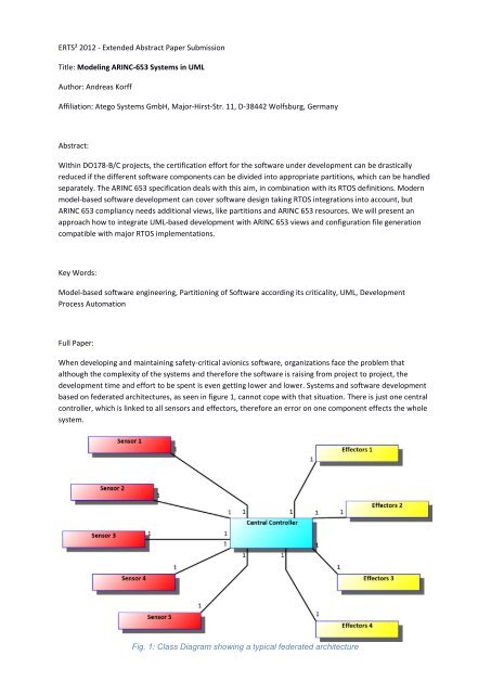
When develop<strong>in</strong>g and ma<strong>in</strong>ta<strong>in</strong><strong>in</strong>g safety-critical avionics software, organizations face the problem that<br />
although the complexity of the <strong>systems</strong> and therefore the software is rais<strong>in</strong>g from project to project, the<br />
development time and effort to be spent is even gett<strong>in</strong>g lower and lower. Systems and software development<br />
based on federated architectures, as seen <strong>in</strong> figure 1, cannot cope with that situation. There is just one central<br />
controller, which is l<strong>in</strong>ked to all sensors and effectors, therefore an error on one component effects the whole<br />
system.<br />
Fig. 1: Class Diagram show<strong>in</strong>g a typical federated architecture
Every change affect<strong>in</strong>g components <strong>in</strong> use might cause a different tim<strong>in</strong>g, so schedul<strong>in</strong>g is affected and<br />
consequences must be checked carefully. This <strong>in</strong>creases the work needed to tackle obsolescence and reduces<br />
to chance for re-us<strong>in</strong>g any part of the system.<br />
In order to overcome high ma<strong>in</strong>tenance costs and low re-use potential for avionics software, we should have a<br />
closer look on the typical layers <strong>in</strong> the central controller. On the very outside, an <strong>in</strong>terface layer to the physical<br />
world is a common pattern, allow<strong>in</strong>g to control the real-world sensors and effectors. Before process<strong>in</strong>g the<br />
data is possible, a second layer for data formatt<strong>in</strong>g is usual as well. The third layer is then responsible to do the<br />
calculations and data process<strong>in</strong>g. These three layers are shown <strong>in</strong> figure 2, together with their mapped<br />
representative, appropriate layers <strong>in</strong> the Stanag 4626/EN 4660 (ASAAC) def<strong>in</strong>ition. The uppermost Data<br />
Process<strong>in</strong>g Layer <strong>in</strong> the federated architectures does not need to be responsible for schedul<strong>in</strong>g anymore, s<strong>in</strong>ce<br />
this is done <strong>in</strong> the operat<strong>in</strong>g system layer. On the other hand, the data formatt<strong>in</strong>g is not handled normally on<br />
OS level; therefore the application has to do this accord<strong>in</strong>gly. The physical <strong>in</strong>terface layer maps perfectly on the<br />
module support layer.<br />
Federated Architecture<br />
Data Process<strong>in</strong>g Layer<br />
{maps for logic}<br />
{maps for schedul<strong>in</strong>g}<br />
Stanag 4626/EN 4660 (ASAAC)<br />
Application Layer<br />
Data Format<strong>in</strong>g Layer<br />
{maps}<br />
Operat<strong>in</strong>g System Layer<br />
Physical Interface Lacer<br />
{maps}<br />
Module Support Layer<br />
Fig. 2: Federated Layers and their appropriate layer <strong>in</strong> ASAAC<br />
Based on these three layers for application, OS and module support, we can now def<strong>in</strong>e components <strong>in</strong> the<br />
application layer, as seen <strong>in</strong> figure 3, for e.g. one hardware node. In the application layer, the different system<br />
functions are split <strong>in</strong>to <strong>in</strong>dependent, possibly re-usable components, like Autopilot, Navigation, or Telemetry.<br />
The components do not <strong>in</strong>teract directly; <strong>in</strong>stead they are us<strong>in</strong>g standardized <strong>in</strong>ter-component communication<br />
means, provided by the OS Layer. Access<strong>in</strong>g the node hardware is done us<strong>in</strong>g dedicated components on the<br />
Module Support Layer.<br />
S<strong>in</strong>ce it is necessary to support a network topology of more than just one hardware node, the OS Layer is also<br />
responsible to manage the activity on each node <strong>in</strong> addition to the communication use cases on one node. We<br />
could visualize this by display<strong>in</strong>g multiple Open Architecture Hardware Nodes, with the OS Layers be<strong>in</strong>g<br />
connected.
This all results <strong>in</strong> an architecture, which consists of de-coupled application partition, which can be certified<br />
<strong>in</strong>dependently, if the underly<strong>in</strong>g OS Layer, respectively its implementation supports and guarantees these<br />
rules.<br />
Fig. 3: Open Architecture Hardware Node show<strong>in</strong>g partitioned application components<br />
With the <strong>ARINC</strong> <strong>653</strong> (Avionics Application Standard Software Interface) standard, organizations implement<strong>in</strong>g<br />
Integrated Modular Avionics (IMA) architectures, as described above, ga<strong>in</strong> benefits <strong>in</strong> several areas:<br />
1. Due to the partition<strong>in</strong>g of the system, the overall system robustness can be <strong>in</strong>creased or ma<strong>in</strong>ta<strong>in</strong>ed.<br />
2. Typically system applications have assigned different safety <strong>in</strong>tegrity levels (SIL), which corresponds to<br />
their certification effort. Be<strong>in</strong>g able to group the applications <strong>in</strong>to different <strong>ARINC</strong> <strong>653</strong> partitions<br />
reflect<strong>in</strong>g their safety <strong>in</strong>tegrity level, this drastically reduces the certification effort to the m<strong>in</strong>imum for<br />
each of these levels.<br />
3. The re-certification effort is also drastically reduced to the partitions affected.<br />
4. There is a standardized API to de-couple application code from the RTOS <strong>in</strong> use, called APEX<br />
(APplication EXecutive). APEX also offers standardized communication mechanisms.<br />
A standard is always only as good as its implementation. Several RTOS suppliers, like W<strong>in</strong>d River® or SYSGO®,<br />
offer support for <strong>ARINC</strong> <strong>653</strong>, all <strong>in</strong>clud<strong>in</strong>g an APEX API for the different programm<strong>in</strong>g languages supported and<br />
<strong>in</strong> use, like C or Ada. In addition, there is the need <strong>in</strong> <strong>ARINC</strong> <strong>653</strong> to def<strong>in</strong>e the relevant structural elements like<br />
application partitions, the communication paths and “health monitor<strong>in</strong>g” def<strong>in</strong>itions. All of these<br />
configurations are made textually us<strong>in</strong>g XML.<br />
On the other hand, <strong>UML</strong>-based development is commonly and successfully used for software-centric projects,<br />
also <strong>in</strong> the Aerospace doma<strong>in</strong>. Here, more and more projects are us<strong>in</strong>g model-based development for exactly<br />
the same reasons like for us<strong>in</strong>g <strong>ARINC</strong> <strong>653</strong>: Scalability, traceability, ma<strong>in</strong>ta<strong>in</strong>ability, communication, and the<br />
ability to check completeness and correctness. Most of the projects are comb<strong>in</strong><strong>in</strong>g both levels of abstraction,<br />
on one hand the <strong>UML</strong> model for design<strong>in</strong>g the overall structure and to l<strong>in</strong>k the different perspectives like<br />
structure, behavior and non-functional constra<strong>in</strong>ts, and on the other hand the code level for implementation<br />
details. Model-to-text transformations exist to connect these two levels, like the Automatic Code Synchronizer<br />
<strong>in</strong> Artisan Studio, which also can take the RTOS used <strong>in</strong>to account.<br />
Us<strong>in</strong>g the <strong>UML</strong> as a basis with its generic extensibility us<strong>in</strong>g profiles, we can br<strong>in</strong>g this all together <strong>in</strong> one<br />
model.<br />
In order to avoid the sometimes very cumbersome and error-prone def<strong>in</strong>ition of the XML files for the <strong>ARINC</strong><br />
<strong>653</strong> configuration, the idea is now to
1. Def<strong>in</strong>e a <strong>UML</strong> profile accord<strong>in</strong>g a meta-model, which reflects all the elements and their associations<br />
for <strong>ARINC</strong> <strong>653</strong> configurations. This can be done e.g. by the tool vendor, who offers this standard<br />
extension<br />
2. Stereotype <strong>UML</strong> diagrams to support the views needed to model the necessary elements for <strong>ARINC</strong><br />
<strong>653</strong>, as described here<br />
3. Def<strong>in</strong>e a model-to text transformation, which generates the appropriate XML files for the IDE <strong>in</strong> use<br />
A <strong>UML</strong> profile consists of a cohesive set of stereotypes and tag def<strong>in</strong>itions, which extend ord<strong>in</strong>ary <strong>UML</strong> metatypes,<br />
like class, operation, or role. Normally, these extended model elements, like for <strong>in</strong>stance a class be<strong>in</strong>g<br />
stereotyped with «Module» represent<strong>in</strong>g an <strong>ARINC</strong> <strong>653</strong> Module, can only be shown on diagrams which display<br />
the appropriate meta-type, class. Some <strong>UML</strong> tools allow def<strong>in</strong><strong>in</strong>g stereotypes on <strong>UML</strong> diagram types, <strong>in</strong>clud<strong>in</strong>g<br />
the toolbar commands or menu entries when us<strong>in</strong>g the diagram. Figure 5 shows a specific diagram toolbar for<br />
an <strong>ARINC</strong> <strong>653</strong> Configuration Diagram, which is def<strong>in</strong>ed on top of a <strong>UML</strong> Composite Structure Diagram.<br />
Fig. 4: A Toolbar for modell<strong>in</strong>g an <strong>ARINC</strong> <strong>653</strong> Configuration Diagram<br />
Extend<strong>in</strong>g the <strong>UML</strong> Composite Structure Diagrams with relevant tags and stereotypes as shown <strong>in</strong> figure 5, the<br />
software designer now can def<strong>in</strong>e the system and software structure for an <strong>ARINC</strong> <strong>653</strong> project, by giv<strong>in</strong>g him a<br />
graphical means to model everyth<strong>in</strong>g around the <strong>ARINC</strong>-specific configuration of partitions and communication<br />
elements. The configuration diagram shows one node, def<strong>in</strong>ed as , which conta<strong>in</strong>s three partitions<br />
as stereotyped parts. Accord<strong>in</strong>g the normal DO178-B/C def<strong>in</strong>itions, they are named with the relevant criticality<br />
levels DAL A to C. As an example, we have modeled the navigation application on partition DAL_B and its<br />
controlled communication as queu<strong>in</strong>g ports connect<strong>in</strong>g this application with the Autopilot application on the<br />
DAL_C partition. They <strong>in</strong>terchange the position <strong>in</strong>formation us<strong>in</strong>g a controlled channel.<br />
«Module»<br />
Open Architecture Hardware NodeModule<br />
«SystemHMTable»<br />
systemHm :<br />
«PartitionHMTable»<br />
partHm :<br />
«ModuleHMTable»<br />
moduleHm :<br />
«Partition Part»<br />
DAL_A<br />
«Application Part»<br />
Eng<strong>in</strong>e Management<br />
«Partition Part»<br />
DAL_B<br />
«Application Part»<br />
Navigation<br />
«Process Part»<br />
UpdatePos<br />
«Channel»<br />
positionChannel<br />
«Queu<strong>in</strong>gPort»<br />
PosData<br />
«Partition Part»<br />
DAL_C<br />
«Queu<strong>in</strong>gPort»<br />
PosData<br />
«Application Part»<br />
Autopilot<br />
«Application Part»<br />
Telemetry<br />
«Process Part»<br />
UpdateDisplays<br />
«SharedLibrary»<br />
vxSysLib :<br />
Fig. 5: An <strong>ARINC</strong> <strong>653</strong> Configuration Diagram shows partitions, applications and processes
It is also important to note that <strong>in</strong> addition of the automatic application of the <strong>ARINC</strong> <strong>653</strong> stereotypes, the<br />
diagram tools allow to apply the <strong>ARINC</strong> <strong>653</strong>-specific semantics, so e.g. only compatible ports can be connected<br />
to def<strong>in</strong>e the communication between <strong>ARINC</strong> <strong>653</strong> partitions. Extend<strong>in</strong>g the typical model<strong>in</strong>g steps with profilespecific<br />
functionality can also automate many model<strong>in</strong>g actions the user normally would have to manually. In<br />
order to be effective, the tool support should do as much construction work automatically and then help the<br />
user fill<strong>in</strong>g out the automatically generated templates, e.g. <strong>in</strong>dicat<strong>in</strong>g a graphical model<strong>in</strong>g error like <strong>in</strong> figure<br />
Fig. 6: A typical <strong>ARINC</strong> configuration dialog for <strong>in</strong>dicat<strong>in</strong>g an user error<br />
In parallel to the model-based development of the software structure and behavior expressed <strong>in</strong> the<br />
appropriate programm<strong>in</strong>g- language, thus generat<strong>in</strong>g C or Ada form the <strong>UML</strong> class and state model, there are<br />
additional gaps to fill, like generat<strong>in</strong>g the <strong>ARINC</strong> <strong>653</strong> configuration XML files and the relevant <strong>in</strong>itialization code<br />
<strong>in</strong> the used programm<strong>in</strong>g language. Both tasks can be fulfilled by chang<strong>in</strong>g the transformation rules from the<br />
model to code or text files. S<strong>in</strong>ce generators like the Artisan Studio® Automatic Code Synchronizer can<br />
analyze every aspect of the model, like e.g. the elements def<strong>in</strong>ed us<strong>in</strong>g the <strong>ARINC</strong> <strong>653</strong> Profile, and then<br />
generate files based on rules def<strong>in</strong>ed <strong>in</strong> the Artisan Studio Transformation Development Kit, the full set of<br />
code and configuration files can be automatically and cont<strong>in</strong>uously generated from the amended <strong>UML</strong> model.<br />
As an small example of the many XML configuration files be<strong>in</strong>g generated, the navigation application<br />
configuration is shown here, <strong>in</strong>dicat<strong>in</strong>g e.g. the modeled queu<strong>in</strong>g port:<br />
<br />
<br />
<br />
<br />
<br />
<br />
<br />
<br />
<br />
As this generation process for both the XML code and the programm<strong>in</strong>g language code is work<strong>in</strong>g <strong>in</strong> the<br />
background, the modeler can add the implementation details <strong>in</strong> his standard code IDE used for the chosen<br />
RTOS implementation for <strong>ARINC</strong> <strong>653</strong>. This results <strong>in</strong> an automatic and coherent update of any structural change<br />
of the <strong>ARINC</strong> <strong>653</strong> system, s<strong>in</strong>gle-sourced by the amended <strong>UML</strong> model. For the navigation application, the<br />
applicable startup code is shown below:<br />
#<strong>in</strong>clude "Navigation.h"<br />
#<strong>in</strong>clude "UpdatePos.h"
PROCESS_ID_TYPE UpdatePos_id;<br />
QUEUING_PORT_ID_TYPE PosData_id;<br />
void usrAppInit()<br />
{<br />
#ifdef USER_APPL_INIT<br />
USER_APPL_INIT; /* for backwards compatibility */<br />
#endif<br />
PROCESS_ATTRIBUTE_TYPE UpdatePos_attr;<br />
static const char UpdatePos_name[] = "UpdatePos";<br />
RETURN_CODE_TYPE rc;<br />
<strong>in</strong>t i;<br />
for(i = 0; i