A SysML/MARTE high level methodology for real-time - Embedded ...
A SysML/MARTE high level methodology for real-time - Embedded ...
A SysML/MARTE high level methodology for real-time - Embedded ...

You also want an ePaper? Increase the reach of your titles
YUMPU automatically turns print PDFs into web optimized ePapers that Google loves.
MADES: A <strong>SysML</strong>/<strong>MARTE</strong> <strong>high</strong> <strong>level</strong><strong>methodology</strong> <strong>for</strong> <strong>real</strong>-<strong>time</strong> and embedded systemsImran Rafiq Quadri ∗ , Andrey Sadovykh ∗∗ Softeam, 21 Avenue Victor Hugo,75016 Paris, FranceEmail:{Firstname.Lastname}@softeam.frLeandro Soares Indrusiak †† University of York,York, United KingdomEmail:lsi@cs.york.ac.ukAbstract—Rapid evolution of <strong>real</strong>-<strong>time</strong> and embedded systems(RTES) is continuing at an increasing rate, and new methodologiesand design tools are needed to reduce design complexitywhile decreasing development costs and integrating aspects suchas verification and validation. Model-Driven Engineering offersan interesting solution to the above mentioned challenges and isbeing widely used in various industrial and academic researchprojects. This paper presents the EU funded MADES projectwhich aims to develop novel model-driven techniques to improveexisting practices in development of RTES <strong>for</strong> avionics andsurveillance embedded systems industries. MADES proposes asubset of existing UML profiles <strong>for</strong> embedded systems modeling:namely <strong>MARTE</strong> and <strong>SysML</strong>, and is developing new tools andtechnologies that support design, validation, simulation andeventual automatic code generation, while integrating aspectssuch as component re-use. In this paper, we first introducethe MADES language, which enables rapid system design andspecification that can be then taken by underlying MADES tools<strong>for</strong> goals such as simulation or code generation. Finally, weillustrate the various concepts present in the MADES languageby means of a car collision avoidance system case study.Index Terms—Real-Time and <strong>Embedded</strong> Systems, Model-Driven Engineering, <strong>SysML</strong>, <strong>MARTE</strong>, MADES languageI. INTRODUCTION<strong>Embedded</strong> systems have become an essential aspect ofour professional and personal lives. From avionics, transport,defense, medical and telecommunication systems to generalcommercial appliances such as smart phones, gaming consoles;these systems with <strong>real</strong> <strong>time</strong> constraints: Real-Timeand <strong>Embedded</strong> Systems (RTES) are now omnipresent, and itis difficult to find a domain where these miniaturized systemshave not made their mark. The important characteristicsof RTES include: low power consumption, reduced thermaldissipation and radiation emissions, among others; offeringadvantages and new opportunities to integrate more powerful,energy efficient processors, peripherals and related resourcesinto the system.A. MotivationsHowever, as computing power increases, more functionalitiesare expected to be <strong>real</strong>ized and integrated into anembedded system. Un<strong>for</strong>tunately, the fallout of this complexityis that the system design (particularly software design) doesnot evolve at the same pace as that of hardware due to issuessuch as development budget limitations, reduction of productlife cycles and design <strong>time</strong> augmentation. Additionally, developmentcosts and <strong>time</strong> to market shoot up proportionally.Without the usage of effective design tools and methodologies,large complex RTES are becoming increasingly difficult tomanage, resulting in critical issues and what has finally led tothe famous productivity gap. The design space, representingall technical decisions that need to be elaborated by the designteam is there<strong>for</strong>e, becoming difficult to explore. Similarly,manipulation of these systems at low implementation <strong>level</strong>ssuch as Register Transfer Level (RTL) can be hindered byhuman interventions and the subsequent errors.Thus effective design methodologies are needed to decreasethe productivity gap, while resolving issues such as relatedto system complexity, verification and validation, etc. Amongseveral possibilities, elevation of design abstraction <strong>level</strong>sseems the most promising one. High abstraction <strong>level</strong> basedsystem design approaches have been developed in this context,such as Model-Driven Engineering (MDE) [1] that specifythe system using the UML (Unified Modeling Language)graphical language.B. Elevating design abstraction <strong>level</strong>sMDE enables <strong>high</strong> <strong>level</strong> system modeling of both softwareand hardware, with the possibility of integrating heterogeneouscomponents into the system. It allows system <strong>level</strong>(application/architecture) modeling at a <strong>high</strong> specification <strong>level</strong>permitting several abstraction stages, each with a specific viewpoint. This Separation of Views (SoV) enables a designerto focus on a domain aspect related to an abstraction stagethus permitting a transition from solution space to problemspace. Using UML <strong>for</strong> system description increases the systemcomprehensibility as it enables designers to provide <strong>high</strong><strong>level</strong>descriptions of the system, that easily illustrate theinternal concepts (data dependencies, hierarchy, etc.). Thesespecifications can be reused, modified or extended due to theirgraphical nature. Thus, MDE offers an interesting solutionto the above mentioned challenges and is being widely usedin various industrial and academic research projects. It issupported by different technologies and tools such UML andrelated profiles <strong>for</strong> <strong>high</strong> <strong>level</strong> system specifications. Moreover,Model trans<strong>for</strong>mations [2] can then automatically generateexecutable models or code from these abstract <strong>high</strong> <strong>level</strong>design models.
C. Our contributionsHere, we first provide an overview of the MADES projectfollowed by our contributions. MADES [3], [4] is an EUfunded FP7 project which aims to develop novel modeldriventechniques to improve existing practices in developmentof <strong>real</strong>-<strong>time</strong> and embedded systems <strong>for</strong> avionics andsurveillance embedded systems industries. MADES proposesan effective subset of existing UML profiles <strong>for</strong> embeddedsystems modeling: namely <strong>SysML</strong> [5] and <strong>MARTE</strong> [6], andis developing new tools and technologies that support design,validation, simulation and eventual automatic code generation,while integrating aspects such as component re-use.The contributions of this paper relate to presenting a complete<strong>methodology</strong> <strong>for</strong> the design of RTES using a combinationof both <strong>SysML</strong> and <strong>MARTE</strong>, while avoiding incompatibilitiesresulting from simultaneous usage of both profiles. While alarge number of works deal with embedded systems specificationsusing only either <strong>SysML</strong> or <strong>MARTE</strong>, we aim to presenta combined approach and illustrate the advantages of using thetwo profiles. This contribution is significant in nature as whileboth these profiles provide numerous concepts and supportingtools, they are in turn difficult to be mastered by systemdesigner. For this purpose, we present the MADES language,which associated with the namesake project focuses on aneffective subset of <strong>SysML</strong> and <strong>MARTE</strong> profiles and proposesa specific set of unique diagrams <strong>for</strong> expressing differentaspects related to a system. In the paper, an overview of theMADES language and the associated diagrams is presented,that enables rapid design and progressive composition ofsystem specifications. The resulting models then can be takenby underlying MADES tools <strong>for</strong> goals such as simulation orautomatic code generation.Finally, we illustrate the various concepts present in theMADES language by means of an effective <strong>real</strong> life embeddedsystems case study: a car collision avoidance system thatintegrates the MADES language and illustrates the differentphases of our developed design <strong>methodology</strong>.The rest of this paper is organized as follows: section IIillustrates some related works, while section III gives a briefoverview of the MADES project, followed by a summarizeddescription of the MADES language in section IV. Afterwards,section V presents our case study followed by a conclusion insection VI.II. RELATED WORKSWhile a large number of researches exist that make use ofeither <strong>SysML</strong> or <strong>MARTE</strong> <strong>for</strong> <strong>high</strong> <strong>level</strong> modeling of embeddedsystems, due to space limitations, it is not possible here to givean exhaustive description and we only provide a brief summaryon some of the works that make use of <strong>SysML</strong> or <strong>MARTE</strong>based <strong>high</strong> abstraction <strong>level</strong>s and Model-Driven Engineering,<strong>for</strong> RTES design and implementation.The MoPCoM project [7] uses <strong>MARTE</strong> profile to targetmodeling and code generation of reconfigurable embeddedsystems. While the project inspires from <strong>SysML</strong> concepts suchas requirements and blocks, they are not fully integrated inthe design flow. The project uses the IBM Harmony 1 processcoupled with Rhapsody 2 UML modeling tool. Additionally,MoPCoM proposes two distinct flows <strong>for</strong> system modeling andschedulability analysis that increase design ef<strong>for</strong>ts. Similarly,eDIANA [8] is an ARTEMIS project that uses <strong>MARTE</strong> profile<strong>for</strong> RTES specification and validation. However, detailed specificationof software and hardware aspects are not illustratedin the project. While TOPCASED [9] differs from MADES,as it focuses primarily on IDE infrastructure <strong>for</strong> embeddedsystems and not on particular implementations.Project SATURN is [10] is another EU FP7 project that aimsto use <strong>high</strong> <strong>level</strong> co-modeling approach <strong>for</strong> RTES simulationand synthesis goals. However, the project only takes <strong>SysML</strong>into account and proposes a number of UML profiles <strong>for</strong>co-simulation, synthesis and code generation purposes. Thegoal is to use carry out hardware/software modeling via theseprofiles and generate SystemC <strong>for</strong> eventual VHDL translationand FPGA implementation. Un<strong>for</strong>tunately, the project does notutilizes the <strong>MARTE</strong> profile <strong>for</strong> hardware/software co-designmodeling. In [11], the authors provide a mixed modelingapproach based on <strong>SysML</strong> and the <strong>MARTE</strong> profiles to addressdesign space exploration strategies. However, the shortcomingsof this approach is that they only provide implementationresults by means of mathematical expressions and no actualexperimental results were illustrated.The OMEGA European project [12] is also dedicated tothe development of critical <strong>real</strong>-<strong>time</strong> systems. However it usespure UML specifications <strong>for</strong> system modeling and proposes aUML profile [13], which is a subset of the earlier UML profile<strong>for</strong> Scheduling, Per<strong>for</strong>mance and Time (SPT), that has beenintegrated in <strong>MARTE</strong>. The <strong>MARTE</strong>S project emphasizes oncombined usage of UML and SystemC <strong>for</strong> systematic modelbaseddevelopment of RTES. The results from this project inturn, have contributed to the creation of the <strong>MARTE</strong> profile.While INTERESTED [14] proposes a merged <strong>SysML</strong>/<strong>MARTE</strong><strong>methodology</strong> where <strong>SysML</strong> is used <strong>for</strong> requirement specificationsand <strong>MARTE</strong> <strong>for</strong> timing aspects, it does not proposesrules on combined usage of both profiles.The MADES project aims to resolve this issue and thusdifferentiates from the above mentioned related works, asit focuses on an effective language subset combining both<strong>SysML</strong> and <strong>MARTE</strong> profiles <strong>for</strong> rapid design and specificationof RTES. The two profiles have been chosen as they are bothwidely used in embedded systems design, and are complimentaryin nature [15]. MADES proposes automatic generationof hardware descriptions and embedded software from <strong>high</strong><strong>level</strong> models, and integrates verification of functional and nonfunctionalproperties, as illustrated in the following section.III. MADES: GOALS AND METHODOLOGYIn this section, we provide a brief overview of the MADESdesign <strong>methodology</strong>, as illustrated in Fig.1. Initially, the <strong>high</strong><strong>level</strong> system design models are carried out using the MADES1 http://www-01.ibm.com/software/rational/services/harmony/2 http://www-01.ibm.com/software/awdtools/rhapsody/
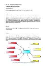
figure illustrates some basic scenarios, such as the car beingstarted, stopped or being driven. The Avoid Collisionsscenario makes use of other specified scenarios and is theone that is related to the system requirements described in thesection.V-A1.3) High Level Specification: Once the requirements anduse case scenarios of our system are specified; we moveonto the functional block description of the CCAS systemas described in Fig.6. For this, MADES High Level BlockSpecification or High Level Internal Block Specification diagramsare used. This conception phase enables a designer todescribe the system functionality without going into detailshow the functionality is to be eventually implemented. Herethe functional specification is described using <strong>SysML</strong> blockdefinition diagram concepts. The functional description canbe specified by means of UML concepts such as aggregation,inheritance, composition etc. Equally, hierarchical compositionof functional blocks can be specified by means of internalblocks, ports and connectors. Here we use these concepts<strong>for</strong> describing the global composition of the CCAS. TheCar block is composed of some system blocks such as aIgnition System,Charging System,Starting System,Engine Component Parts,Transmission System and finallytheCar Collision Avoidance Module which is themain component related to our case study. Each functionalblocks can be composed of internal blocks, however, this stephas not been illustrated in the paper. >A i r Co n d i t i o n e r Sy s t e m >El e c t r i c Su pp l y Sy s t e m >A u d i o / Vi d e o Mu l t i m e d i a De v i c e s >Ch a r g i n g Sy s t e m >Ga u g e s a n d Me t e r s >I g n i t i o n Sy s t e m >Sw i t c h e s >St a r t i n g Sy s t e m >Doo r s12 ..*110 ..10 ..10 ..10 ..10 ..11 ..*0 ..110 ..11 0 ..10 ..1 0 ..10 ..1 0 ..10 ..10 ..10 ..10 ..11111 >W i n d o w s >Ca r >10 ..1110 ..10 ..1 1En g i n e Coo li n g Sy s t e mW h ee l a n d Ti r e Pa r t s1111 > >En g i n e Co m p o n e n t Pa r t s >Ca r Co lli s i o n A v o i d a n c e Mo d u l e >W i r i n g Ha r n e ss e sSu s p e n s i o n a n d St ee r i n g Sy s t e m > >Tr a n s m i ss i o n Sy s t e m >Ex h a u s t Sy s t e m > >Fu e l Su pp l y Sy s t e mEn g i n e Oil Sy s t e mFigure.6: High <strong>level</strong> specification using <strong>SysML</strong> block conceptsGl o b a l Co lli s i o n A v o i d a n c e St r a t e g yDetect Colli sion by m eans of theinstalled radar detection or by theim age track ing sy stem . Switchingbetwee n radar and im age track ingdepending upon user requirem ents andweather conditions. Tak e app ropriateactions to av oid colli sions and notifythe driv erA v o i d Co lli s i o n sspecification of our system, it is possible <strong>for</strong> us to completethe requirement specifications, as described in Fig.7.As seen here, a related use case scenario and a functionalblock has been added to the figure, which helps to completeand satisfy the <strong>high</strong> <strong>level</strong> system requirements. It should benoted here, that as seen in Fig.7, only theCar CollisionAvoidance Module block specified in the diagram is utilizedto satisfy the global system requirements. Thus, these systemrequirements can be refined once an initial functional specificationof system is completed. Since we are only interestedin the Car Collision Avoidance Module and not otherfunctional blocks of the car, it is this module that is the focusof the subsequent design phases.B. <strong>MARTE</strong> based modeling of CCASOnce the initial design descriptions have been specified, it ispossible to partition and enrich the <strong>high</strong> <strong>level</strong> functionalities.For this, <strong>MARTE</strong> concepts are used to determine whichparts of the system are implemented in software or hardwa<strong>real</strong>ong with their eventual allocation. Additionally, <strong>MARTE</strong>profile enables to express non-functional properties relatedto a system, such as throughput, worst case execution <strong>time</strong>s,etc. We now describe the <strong>MARTE</strong> based design phases in thesubsequent sections.1) Refined High Level Specification: We now turn towardsthe <strong>MARTE</strong> based modeling of the CCAS. All necessaryconcepts present at the High Level Specification Diagramcorrespond to an equivalent concept at the Refined HighLevel Specification Diagram. Since we are only interested intheCar Collision Avoidance Module at the <strong>high</strong>er <strong>level</strong>specifications, an equivalent <strong>MARTE</strong> component is created.TheRH Car Collision Avoidance Module is stereotypedas a <strong>MARTE</strong>RtUnit that determines the active nature of thecomponent. Fig.8 shows the related modeling of this concept.TheRtUnit modeling element is the basic building block thatpermits to handle concurrency in RTES applications [6]. Itshould be mentioned that component structure and hierarchyshould be preserved between the two <strong>high</strong> <strong>level</strong> specificationdiagrams. As in this particular example, no hierarchical compositionsare present at the <strong>high</strong> <strong>level</strong> specifications <strong>for</strong>CarCollision Avoidance Module, they are equally not presentin the underlying refined <strong>high</strong> <strong>level</strong> specifications. >RH_ Ca r Co lli s i o n A v o i d a n c e Mo d u l eI mm i n e n t Co lli s i o n St r a t e g yA dd i t i o n a l Ti m i n g r e q u i r e m e n t s Ne a r Co lli s i o n A v o i d a n c e St r a t e g yCh a n g i n g La n e s St r a t e g yFigure.8: Refined <strong>high</strong> <strong>level</strong> specification of the CCASWhen ex ternal obj ect is less than 2m eters away , the driv er should benotified by an alarm and HUD, andsy stem should switch to a criticalwarning state. I f the sy stem rem ains incritical warning state f or m ore than 300m s and distance f rom obj ect is still lessthan 2 m eters then the engine should bestopp ed, brak es should be app lied,seatbelts should be tensioned and airbag should be deploy ed. The brak esshould be app lied f or 100 m sThe radar or the im age track ingm odule should send the data to theController ev ery 100 m s v ia thesy stem bus and the comm un icationshould tak e 20 m s, during whichthe bus should be busy . I n case ofimm inent colli sion, the controllershould send the brak e comm andwhich should tak e no m ore than 20m sWhen ex ternal obj ect is less than 3m eters away , the controller shouldswi tch to a warning state. I f the sy stemrem ains in this state f or 300 m s, thenthe driv er should b e notified v ia analarm and HUD, norm al b rak es shouldbe app lied <strong>for</strong> 10 m s f or reducing carspee d. Hazard warning lights should beactiv ated in the HUD.When the driv er is about tochange lanes or if the cardev iates f rom the curr entlane intentionally , the driv ershould b e notified v ia theHUD. I f the driv er is chaninglanes him self, the car turnsignal should be on >Ca r Co lli s i o n A v o i d a n c e Mo d u l e {kind (hybrid), nature (spatialAllocation)} >Ca r Co lli s i o n A v o i d a n c e Mo d u l eFigure.7: Completing the functional specifications of theCCAS >RH_ Ca r Co lli s i o n A v o i d a n c e Mo d u l eFigure.9: Allocation between <strong>high</strong> <strong>level</strong>/refined <strong>high</strong> <strong>level</strong>specifications4) Completing the Requirement Specifications: Once wehave finished the use case scenarios and functional block2) Allocating High Level and Refined High Level Specifications:Afterwards, an allocation using the MADES Allocation
Diagram is used to map the <strong>high</strong> <strong>level</strong> specification conceptsto the refined <strong>high</strong> <strong>level</strong> specification concepts. This aspectis represented in Fig.9. Using the <strong>MARTE</strong> allocation mechanism,we express that the allocation is hybrid (both structuraland behavioral aspects are thus related from source to target)and spatial in nature.3) Clock Specification: Once the initial specification hasbeen carried out, modeling of hardware and software aspectsof the required functionality is possible in a parallel manner.For that purpose, we first model the different clock types whichare used by the execution plat<strong>for</strong>m of the CCAS, as illustratedin Fig.10. Here, an initial ideal clock type serves as the basis<strong>for</strong> theHardware andSystem clock types. All the clockstypes are discrete in nature using the <strong>MARTE</strong> Time package.hardware components. Here, the hardware specification alsocontains a clocksysclk of the typeSystemClock specifiedearlier in Fig.10. Here using the <strong>MARTE</strong> Time package, weadd a clock constraint onto the clock, specifying that this clock(and related clock type) runs at a rate 10 <strong>time</strong>s faster than thatof the ideal clock.The hardware specification contains different hardwarecomponents which themselves are either further composedof sub components, or have internal behaviors, expressed bymeans of classic UML behavioral diagrams. We now describethe internal behavior of three hardware components:receivingDataSystemClock CCAS Time Domain >I d e a l Cl o c k { n a t u r e ( d i s c r e t e ) , i s Lo g i c a l } >Ha r d w a r e Cl o c k { n a t u r e ( d i s c r e t e ) , r e s o l A tt r ( 10 ) }Figure.12: Behavior of the radar module present in the CCAS >Sy s t e m Cl o c k { n a t u r e ( d i s c r e t e ) , r e s o l A tt r ( 10 ) }Figure.10: Specification of clock types related to CCASWe first define <strong>time</strong> domain to contain the clock typesrelated to the system. For this, a packageCCAS Time Domainstereotyped asTimedDomain is created, respecting the timingnotions in <strong>MARTE</strong>. Afterwards, we specify the clocktypes present in our system as illustrated in the figure. Wespecify three clock types: IdealClock, SystemClock andHardwareClock; all appropriately stereotyped asClockType.TheIdealClock is the basic clock type present in the systemreferencing a certain frequency, while the other two referencethis basic clock and run at much <strong>high</strong>er frequencies.notifyDistanceEnd [distance < 3 meters]warningnotifyDistanceEnd [distance > 3 meters]notifyDistanceEnd [distance < 3 meters && @warning.exit - @warning.enter < 300 ms]^breakInterrputnoActionnotifyDistanceEnd [distance < 2 meters && @criticalwarning.exit - @criticalwarning.enter < 300 ms]^breakInterrputnotifyDistanceEnd [distance >= 3 meters]criticalwarningnotifyDistanceEnd [distance > 2 meters]notifyDistanceEnd [distance < 2 meters]Figure.13: Behavior of the primary controller of the CCASnotifyNormalBrakeEndnormalBrakingidle [@normalBraking.exit - @normalBraking.enter = 10 ms]C ons traintnotifyEmergencyBrakeEnd{T heSys temC loc khas a rate 10<strong>time</strong>s fas ter thanthe I dealC loc k}emergencyBraking[@emergencyBraking.exit - @emergencyBraking.enter = 100 ms]sys clk:System Clockshared m em :Shared Mem oryctrl:Controllerctrl m em :Controller Mem oryim g proc:Im age Process or Secondar ControllerFigure.14: Internal behavior of the braking systemodm :Obstacle Detection Moduleradar:Radaralarm :Alarmadd sens:Add itional Sensorsligh-sig sys:Lightning and Signaling Systembraking sys:Braking Systemcan:CANim g m em :Im age Process or Mem orycam :Cam eradisplay:HUD Displaybelts:Seat beltsair bag:Air bagFigure.11: Abstract hardware specification of CCAS4) Hardware Specification: At the hardware specification<strong>level</strong>, we first model the abstract hardware concepts of theexecution plat<strong>for</strong>m in Fig.11. The abstract hardware modelingof the execution plat<strong>for</strong>m of the CCAS contains primary andsecondary controllers <strong>for</strong> radar/image tracking modules, theirrespective local and shared memories, system clock and additionalhardware resources (radar and camera modules, brakingsystem, etc.); all of which communicate via a CAN bus. The<strong>MARTE</strong> GRM package stereotypes are applied onto the differenthardware resources: <strong>for</strong> exampleComputingResource<strong>for</strong> the primary and secondary controllers,StorageResource<strong>for</strong> the local and shared memories,CommunicationMedia <strong>for</strong>theCAN bus, whileDeviceResource is used <strong>for</strong> the otherIn Fig.12, we describe the internal behavior of theRadar component by means of a state machine diagram.TheRadarBehavior state machine is stereotyped asTimedProcessing (not shown in the Figure). This permitsto bind the processing of this behavior to <strong>time</strong> bymeans of a clock. Here the Radar remains in a singlereceivingData state and continues to send data to theprimary controller at each tick of theSystemClock, every100 ms. While Fig.13 illustrates the internal behavior ofthe primary controller. The controller contains three states,noAction,warning andcriticalwarning. The controllerinitially remains in thenoAction state when distance fromincoming objects is greater than 3 meters. If the distancedecreases to less than 3 meters, the controller switches toeitherwarning orcriticalwarning state (depending uponthe the related condition) and sends a braking commandto the Braking System. Fig.14 illustrates behavior of theBraking System. It switches to either thenormalBrakingor theemergencyBraking state, depending upon receiving aparticular command from the primary controller.
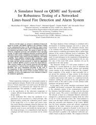
1Ct r l To I m g Ct r l Co mm un i c a t i o nsend switch comm and()1c trlT oI mgC trlC ommunic ation >I m g Co n t r o ll e r Ta s kNotify Im age()SwitchtoRadar()1imgC ontroll erC amC ommunic ationI m g Co n t r o ll e r Ca m Co mm un i c a t i o nsend im age comm and() >Take Picture()Ca m e r a Ta s k >A l a r m Ta s kNotify Alarm Comm and()Soun d Alarm ()1111c amera T as k1alarm T as k11radarO DM C ommunic ation >Ra d a r Ta s kgetData(in data : integer)oDM C ontroll erC ommunic ationradarO DM C ommunic ationRa d a r ODMCo mm un i c a t i o nODMCo n t r o ll e r Co mm un i c a t i o n1send raw data(in data : integer)send sensor distance(in distance : integer)1c trlT oI mgC trlC ommunic ationc ontroll erA irbagC ommunic ationc ontroll erSeatbeltC ommunic ationc ontroll erDis pC ommunic ationc ontroll erLightSys C ommunic ationc ontroll erSens orC ommunic ationc ontroll erA larmC ommunic ation11111111 >ODM Ta s kNotify Raw Data(in raw data : integer)Per<strong>for</strong>m Calculation()c ontroll erBrakeC ommunic ation1oDM C ontroll erC ommunic ation >Co n t r o ll e r Br a k e Co mm un i c a t i o nsend brake comm and()Co n t r o ll e r A i r b a g Co mm un i c a t i o nsend air bag comm and()Co n t r o ll e r Se a t b e l t Co mm un i c a t i o nsend seat belt comm and()Brake Operation()Alarm Operation()Display Upd ate()SwitchtoIm age()Co n t r o ll e r Di s p Co mm un i c a t i o nsend display refresh comm and()Co n t r o ll e r Li g h t Sy s Co mm un i c a t i o nsend lightning system comm and()Co n t r o ll e r Se n s o r Co mm un i c a t i o nsend sensor swee p comm and()Co n t r o ll e r A l a r m Co mm un i c a t i o nsend alarm notification comm and()Co n t r o ll e r Ta s kNotify Distance(in distance : integer)Air Bag Operation()Seat Belt Operation()Lighting Control Operation()Sensor Operation() >Sc h e d u l e r Ti m e rs ys tem Sc hedulerBr a k e A c t u a t o r Ta s kbrake A c tuator T as kNotify Brake()air Bag T as k1 >s eat Belts T as kSe a t Be l t s Ta s k1Notify Seat Belts Comm and()dis play Refres h TNotify as k Display Comm and()1 >light Sys tems T as kLi g h t Sy s t e m s Ta s k1Notify Light Sys Comm and()s ens or T as k10 ..1 >Sy s t e m Sc h e d u l e rPer<strong>for</strong>m Scheduling() >Em ergency Brakes()Norm al Brakes() >A i r Ba g Ta s kNotify Air Bag Comm and()Deploy Air Bag()Tighten Seat Belts() >Di s p l a y Re f r e s h Ta s kRe fresh Display()Indicator Signal() >Notify Sensor Task()Se n s o r Ta s kPer<strong>for</strong>m Weather tem perature sensor swee p()Figure.15: Software specification of the CCASscheduler:System Schedulerodm T:ODM TaskradarT:Radar Taskcomm2ctrlT:Controller Taskcomm10comm 10 :CtrlToIm gCtrlComm un icationimgctrlTcomm11 im gctrlT:Im g Controller Task1 ctrlTcamT comm 11 :Im gControllerCam Comm un icationcam T:Cam era Task1comm11schTim er:Scheduler Tim er1comm 1:RadarODMComm un icationcomm1comm 2:ODMControllerComm un icationcomm31comm8comm41comm91comm5 1comm71comm611comm 6:ControllerSensorComm un icationcomm 3:ControllerDispComm un icationcomm 8:ControllerAirbagComm un icationcomm 4:ControllerSeatbeltComm un icationcomm 9:ControllerBrakeComm un icationcomm 5:ControllerLightSysComm un icationcomm 7:ControllerAlarm Comm un icationsensorT1dispT1abagT1sbeltT1brakeT1lightT1alarmT1sensorT:Sensor TaskdispT:Display Re fresh TaskabagT:Air Bag TasksbeltT:Seat Belts TaskbrakeT:Brake Actuator TasklightT:Light System s Taskalarm T:Alarm TaskFigure.16: Software specification of the CCAS (Instance <strong>level</strong>)5) Software Specification: We now turn towards modelingof the software specification of the execution plat<strong>for</strong>m ofthe CCAS, as displayed in Fig.15. Here, schedulable tasksrelated to the hardware modules are modeled along with theircommunications. A scheduler is also present that manages theoverall scheduling based on a fixed priority algorithm. Thedifferent tasks are stereotyped as SchedulableResource,indicating that they are scheduled by means of a SystemScheduler, itself appropriately stereotyped as aScheduler.Each task contains a number of operations, indicating thefunctionality related to that particular task.The software specification is also modeled at the instance<strong>level</strong> as illustrated in Fig.16, <strong>for</strong> an eventual allocation betweenthe software/hardware specifications, and also <strong>for</strong> schedulabilityanalysis modeling using UML sequence diagrams, asillustrated later on in section V-B12.6) Allocating Software to Hardware: Once the hardwareand software specifications have been carried out, we carry outan allocation between the two using the MADES AllocationDiagram. Here in Fig.17, the majority of the tasks (suchasBrake Actuator Task,Air Bag Task) are allocated tothe primary controller by means of a temporal allocation.Similarly, the Radar and ODM tasks are allocated to theirrespective hardware modules by means of spatial allocations.While tasks related to the secondary controller such asCameraTask are mapped on to it by means of a temporal allocation.Finally, all the communications are allocated to theCAN bus.It should be noted that while the Allocated stereotype on thesoftware and hardware concepts has been applied similarly tothe concepts illustrated in Fig.9, they have not been displayedhere <strong>for</strong> a better visualization. {nature (<strong>time</strong>Scheduling)}cam T:Cam era Taskim gctrlT:Im g Controller Task {nature (<strong>time</strong>Scheduling)}im g proc:Im age Process or Secondar Controllerim g m em :Im age Process or Mem orybraking sys:Braking Systemcam :Cam erabelts:Seat beltsdisplay:HUD Displayair bag:Air bagcan:CANalarm :Alarmadd sens:Add itional Sensorsligh-sig sys:Lightning and Signaling Systemcomm 1:RadarODMComm un icationcomm 2:ODMControllerComm un icationcomm 3:ControllerDispComm un icationcomm 4:ControllerSeatbeltComm un icationcomm 5:ControllerLightSysComm un icationshared m em :Shared Mem oryodm :Obstacle Detection Moduleradar:Radar {nature (<strong>time</strong>Scheduling)}ctrl:Controller {nature (spatialAllocation)} {nature (spatialAllocation)} radarT:Radar Task {nature (<strong>time</strong>Scheduling)} ctrlT:Controller Task {nature (<strong>time</strong>Scheduling)} {nature (<strong>time</strong>Scheduling)} {nature (<strong>time</strong>Scheduling)} {nature (<strong>time</strong>Scheduling)} {nature (<strong>time</strong>Scheduling)} {nature (<strong>time</strong>Scheduling)}ctrl m em :Controller Mem orycomm 6:ControllerSensorComm un icationcomm 7:ControllerAlarm Comm un icationcomm 8:ControllerAirbagComm un icationcomm 9:ControllerBrakeComm un icationcomm 10 :CtrlToIm gCtrlComm un icationcomm 11 :Im gControllerCam Comm un icationodm T:ODM Taskscheduler:System Scheduleralarm T:Alarm Task {nature (<strong>time</strong>Scheduling)}dispT:Display Re fresh TaskbrakeT:Brake Actuator TasksensorT:Sensor TasksbeltT:Seat Belts TasklightT:Light System s TaskabagT:Air Bag TaskFigure.17: Mapping software resources to the hardware modulesof CCAS7) Detailed Hardware Specification: Once the initial abstracthardware specification has been modeled, the designercan move on to modeling of the detailed hardware specificationwhich corresponds more closely to the actual implementationdetails of the execution plat<strong>for</strong>m. The structure of thedetailed hardware specifications corresponds to the abstractspecifications specified in Fig.11, but have been enriched withadditional details: such as operating frequencies of the primaryand secondary controllers, <strong>for</strong> example. All these aspects havebeen represented in Fig.18. Here, the modeled computingresources are stereotyped asHwProcessor, while memoriesare typed asHwRAM. The sensors, radar and display modulesas typed asHwI O, while remaining hardware concepts arestereotyped as HwDevice. Additionally the communicationmodule, theHW ChannelBox has been typed as aHwMedia.Finally, the execution plat<strong>for</strong>m also contains ahwclk clock oftypeHardwareClock with a related clock constraint.hwclk:HardwareClockhwsharedm em :HW_SharedMemhwodm :HW_ODMhwradar:HW_Radarhwalarm :HW_Alarmhwsens:HW_Sensorshwlss :HW_LightSysC ons traint{T heH ardwareC loc khas the s amerate as theSys temC loc k}hwbss :HW_BrakeSysppc:PowerPC {op_Frequencies (300MHz)}hwchann elbox:HW_Chann elBoxhwctrlm em :HW_ControlMemhwim gctrl:HW_Im gControllerhwim gm em :HW_Im gMemhwcam :HW_Cam erahwdisplay:HW_Displayhwbelts:HW_SeatBeltshwairbag:HW_AirBagFigure.18: Detailed hardware specification of the executionplat<strong>for</strong>m8) Detailed Software Specification: In parallel, a designercan model the detailed software specification, which basicallycorrespond to expressing the concepts related to the underlyingoperating system of the CCAS. While it is possible to carryout detailed modeling of the operating system using <strong>MARTE</strong>SRM concepts, by adding relevant details such as semaphores,deadlocks, memory brokers etc; we chose to only illustratesome basic concepts related to a generic operating system.
Here as seen in Fig.19, the operating system has processes,each of which contains a number of threads. TheOperating System is stereotyped according to SRM conceptsas aSwResource, while theProcess concept is typed asaSwSchedulableResource and aMemoryPartition. Thelatter stereotype indicates an address space which will beshared by the different threads associated with a process. Also,theThread is itself typed asSwSchedulableResource. >Op e r a t i n g Sy s t e mproc es s0 ..1* >Pr o c e s s0 ..1thread1 ..* >Th r e a dFigure.19: Detailed software specification of the executionplat<strong>for</strong>m9) Allocating Hardware to Detailed Hardware Specifications:Once the detailed hardware specification has been modeled,we can carry out an allocation linking hardware to thedetailed hardware specifications. This allocation correspondsto a one to one mapping between the two specifications,and thus determines the refinement of the execution plat<strong>for</strong>m.Thus, it enables to move from abstract classifications to detailscorresponding closely to RTL implementation. For example aController (and its related instance) is mapped to aPowerPCprocessor (and its instance), as shown in Fig.20. It shouldbe mentioned that the Allocated stereotype applied on theallocated source/target concepts is not illustrated in the figure.sys clk:System Clockctrl:Controllerctrl m em :Controller Mem oryim g proc:Im age Process or Secondar Controllerim g m em :Im age Process or Mem oryshared m em :Shared Mem orycan:CANodm :Obstacle Detection Modulehwclk:HardwareClockppc:PowerPChwctrlm em :HW_ControlMemhwim gctrl:HW_Im gControllerhwim gm em :HW_Im gMemhwsharedm em :HW_SharedMemhwchann elbox:HW_Chann elBoxhwodm :HW_ODMbraking sys:Braking Systemair bag:Air bagcam :Cam eraradar:Radaralarm :Alarmbelts:Seat beltsligh-sig sys:Lightning and Signaling Systemdisplay:HUD Displayhwbss :HW_BrakeSyshwairbag:HW_AirBaghwcam :HW_Cam erahwradar:HW_Radarhwalarm :HW_Alarmhwbelts:HW_SeatBeltshwlss :HW_LightSyshwdisplay:HW_Displaythe detailed software specification (the operating system inthis case), in Fig.21. All the tasks and communications a<strong>real</strong>located onto the operating system. While it is also possibleto model the detailed software modeling in a detailed manner(different threads corresponding to the different tasks at softwarespecifications) and then carry a one to one allocation,this aspect has not been carried out in the paper.11) Allocating Detailed Software to Detailed HardwareSpecifications: Finally, once all the detailed specificationsrelated to the software and hardware aspects of the executionplat<strong>for</strong>m have been modeled, it is possible to carry out a finalallocation from the detailed software to the detailed hardwarespecifications. Here, as seen in Fig.22, the operating systemis allocated onto the local memory of the primary controller,by means of a spatial allocation. >Op e r a t i n g Sy s t e m {nature (spatialAllocation), kind (hybrid)}hwctrlm em :HW_ControlMemFigure.22: Allocating the detailed software and hardware specifications12) Schedulability Analysis Specifications: Once the softwareand hardware modeling have been carried out, using theMADES language, it is possible to carry out schedulabilityanalysis at the <strong>high</strong> <strong>level</strong> models. Here, in the followingfigures, we illustrate schedulability analysis aspects related tosome modules of the execution plat<strong>for</strong>m. However, it is equallypossible to analysis the whole system in question.radarT:Radar Taskcomm 1:RadarODMComm un ication send raw data( d ) {execTim e (10 m s,m ax) , (8m s,m in )}odm T:ODM Task Notify Raw Data( d ) {execTim e (10 m s,m ax) , (8m s,m in )}comm 2:ODMControllerComm un icationctrlT:Controller Taskadd sens:Add itional Sensorshwsens:HW_SensorsFigure.20: Allocating hardware/detailed hardware specifications Per<strong>for</strong>m Calculation( ) {execTim e (3m s,m ax) , (2m s,m in )} send sensor distance( d ) {execTim e (10ms,m ax) , (8m s,m in )} Notify Distance( d ) {execTim e (10 m s,m ax) , (8m s,m in )} >A i r Ba g Ta s k > Co n t r o ll e r Ta s k > Ra d a r Ta s k >Sy s t e m Sc h e d u l e r >Se n s o r Ta s k > I m g Co n t r o ll e r Ta s k >Se a t Be l t s Ta s k > Li g h t Sy s t e m s Ta s kFigure.23: Sequence SendSensorDistanceToContrl <strong>for</strong>radar/controller communicationRa d a r ODMCo mm un i c a t i o nCo n t r o ll e r Li g h t Sy s Co mm un i c a t i o nCo n t r o ll e r Br a k e Co mm un i c a t i o nODMCo n t r o ll e r Co mm un i c a t i o nCt r l To I m g Ct r l Co mm un i c a t i o nCo n t r o ll e r Se n s o r Co mm un i c a t i o nCo n t r o ll e r Di s p Co mm un i c a t i o nCo n t r o ll e r A l a r m Co mm un i c a t i o nI m g Co n t r o ll e r Ca m Co mm un i c a t i o nCo n t r o ll e r Se a t b e l t Co mm un i c a t i o nCo n t r o ll e r A i r b a g Co mm un i c a t i o n >Op e r a t i n g Sy s t e m >ODM Ta s k >Di s p l a y Re f r e s h Ta s k >A l a r m Ta s k >Br a k e A c t u a t o r Ta s k >Ca m e r a Ta s kFigure.21: Allocating software/detailed software specifications10) Allocation Software to Detailed Software Specifications:Similarly, the software specification is allocated ontoIn Fig.23, the UML sequence diagram illustrates the communicationflows between the different tasks of the executionplat<strong>for</strong>m. TheradarT instance of theRadar Task sends datato theodmT instance of theODM Task by means of a communication:comm1instance ofRadarODMCommunication. Theinstance of theODM Task after carrying out a noise reductionalgorithm, sends the distance to the instancectrlT of theController Task by means of thecomm2 communicationinstance ofODMControllerCommunication. Using appropriate<strong>MARTE</strong> packages, it is possible to carry out schedulabilityanalysis: such as determination of average and worst caseexecution <strong>time</strong>s <strong>for</strong> these flows. For example, the SaStep
stereotype helps to express worst and best case execution<strong>time</strong>s, whileSaCommStep can additionally express the size ofthe message transmitted or received during the communicationflow. Here, the sequenceSendSensorDistanceToContrl isitself stereotyped as aGaScenario (not shown in the figure),indicating it is one of the possible scenarios related to thesystem. ClockEventSendSensorDistanceToContrl{ResourceUsage_ModelElement_execTime(43ms )}breakInterrputSendBrakeCommand{ResourceUsage_ModelElement_execTime(26ms )}Figure.24: TheCCAS InteractionOverview interactionFinally, an interaction overview diagram as shown in Fig.24,illustrates the overall behavior related to two possible scenarios.The second scenario SendBrakeCommand has notillustrated due to space limitations. While it is possible toinclude other possible scenarios related to the CCAS (suchas switching to camera based mode, applying normal brakes)and carry out a schedulability analysis of the whole CCASexecution plat<strong>for</strong>m, here only a partial analysis has beenshown <strong>for</strong> clarification purposes. Here the figure indicatesthat once the CCAS system starts, it enters into a loop. Itremains in the first scenario while keeps getting clock ticksat regular <strong>time</strong> intervals, as displayed by the ClockEventtyped asGaWorkloadEvent. It keeps executing the first sequenceuntil abrakeInterrupt event occurs, causing thesystem to execute the sequence related to the second scenarioconcurrently. As the system does not stop its execution,no final node has been represented in the figure. Finallythe interactionCCAS InteractionOverview is stereotypedas aGaWorkloadBehavior (not shown in the figure). Thisstereotype is used to specify a set of related system-<strong>level</strong>operations, each associated with its respective behavior andexecuted on the basis of associated (workload) events.VI. CONCLUSIONSThis article aims to present a complete <strong>methodology</strong> integratedin the EU MADES project, <strong>for</strong> the design anddevelopment of <strong>real</strong>-<strong>time</strong> and embedded systems using aneffective subset of UML profiles: <strong>SysML</strong> and <strong>MARTE</strong>. Thepaper presents its contributions by proposing an effectivesubset of the two profiles, <strong>for</strong>ming the basis of MADESlanguage and proposes unique set of diagrams to increasedesign productivity, decrease production cycles and promotesynergy between the different designers/teams working atdifferent domain aspects of the global system in consideration.Our MADES <strong>methodology</strong> could inspire future revisions ofthe <strong>SysML</strong> and <strong>MARTE</strong> profiles and may eventually aid intheir evolution. Finally, the different language concepts andassociated diagrams in the <strong>methodology</strong> have been illustratedin a case study related to a car collision avoidance system.VII. ACKNOWLEDGEMENTSThis research presented in this paper is funded by the EuropeanCommunity’s Seventh Framework Program (FP7/2007-2013) under grant agreement no. 248864 (MADES).REFERENCES[1] OMG, “Portal of the Model Driven Engineering Community,” 2007,http://www.planetmde.org.[2] S. Sendall and W. Kozaczynski, “Model Trans<strong>for</strong>mation: The Heart andSoul of Model-Driven Software Development,” IEEE Software, vol. 20,no. 5, pp. 42–45, 2003.[3] A. Bagnato et al, “MADES: <strong>Embedded</strong> systems engineering approachin the avionics domain,” in First Workshop on Hands-on Plat<strong>for</strong>ms andtools <strong>for</strong> model-based engineering of <strong>Embedded</strong> Systems (HoPES), 2010.[4] MADES, “EU FP7 Project,” 2011, http://www.mades-project.org/.[5] Object Management Group Inc, “Final Adopted OMG <strong>SysML</strong> Specification,”mai 2006, http://www.omg.org/cgi-bin/doc?ptc/06-0504.[6] OMG, “Modeling and Analysis of Real-<strong>time</strong> and <strong>Embedded</strong> systems(<strong>MARTE</strong>),” 2010, http://www.omg.org/spec/<strong>MARTE</strong>/1.0/PDF.[7] A. Koudri et al, “Using <strong>MARTE</strong> in the MOPCOM SoC/SoPC Co-Methodology,” in <strong>MARTE</strong> Workshop at DATE’08, 2008.[8] EDIANA, “ARTEMIS project,” 2011, http://www.artemis-ediana.eu/.[9] TOPCASED, “The Open Source Toolkit <strong>for</strong> Critical Systems,” 2010,http://www.topcased.org/.[10] W. Mueller et al., “The SATURN Approach to <strong>SysML</strong>-based HW/SWCodesign,” in IEEE Computer Society Annual Symposium on VLSI(ISVLSI), 2010.[11] M. Mura et al, “Model-based Design Space Exploration <strong>for</strong> RTESwith <strong>SysML</strong> and <strong>MARTE</strong>,” in Forum on Specification, Verification andDesign Languages (FDL 2008), 2008, pp. 203–208.[12] In<strong>for</strong>mation Society Technologies, “OMEGA: Correct Development ofReal-Time <strong>Embedded</strong> Systems ,” 2009, http://www-omega.imag.fr/.[13] L. Ober et al., “Projet Omega : Un profil UML et un outil pour lamodelisation et la validation de systemes temps reel,” 2005, pp. 73:33–38.[14] INTERESTED, “EU FP7 Project,” 2011, http://www.interestedip.eu/index.html.[15] H. Espinoza et al, “Challenges in Combining <strong>SysML</strong> and <strong>MARTE</strong><strong>for</strong> Model-Based Design of <strong>Embedded</strong> Systems,” in ECMDA-FA’09.Springer-Verlag, 2009, pp. 98–113.[16] D.S. Kolovos et al, “Eclipse development tools <strong>for</strong> Epsilon,” in EclipseSummit Europe, Eclipse Modeling Symposium, 2006.[17] N. Matragkas et al., “D4.1: Model Trans<strong>for</strong>mation and Code GenerationTools Specification,” Tech. Rep., 2010, http://www.mades-project.org/.[18] L. Baresi et al., “D3.1: Domain-specific and User-centred Verification,”Tech. Rep., 2010, http://www.mades-project.org/.[19] ——, “D3.3: Formal Dynamic Semantics of the Modelling Notation,”Tech. Rep., 2010, http://www.mades-project.org/.[20] M. Pradella et al, “The Symmetry of the Past and of the Future: BiinfiniteTime in the Verification of Temporal Properties,” in ESEC-FSE’07. New York, NY, USA: ACM, 2007, pp. 312–320.[21] I. Gray and N. Audsley, “Exposing non-standard architectures to embeddedsoftware using compile-<strong>time</strong> virtualisation,” in Internationalconference on Compilers, architecture, and synthesis <strong>for</strong> embeddedsystems (CASES’09), 2009.[22] Ian Gray et al., “Model-based hardware generation and programming- the MADES approach,” in 14th International Symposium on Objectand Component-Oriented Real-Time Distributed Computing Workshops,2011.[23] Modelio, “UML Modeling tool,” 2011, www.modeliosoft.com.[24] Papyrus, “Open source tool <strong>for</strong> UML modeling,” 2011,http://www.papyrusuml.org/.[25] D.D. Gajski and R. Khun, “New vlsi tools,” IEEE Computer, vol. 16,pp. 11–14, 1983.[26] Xilinx, “MicroBlaze Soft Processor Core ,” 2011,http://www.xilinx.com/tools/microblaze.htm.[27] A. Bagnato et al, “D1.3: MADES Initial Approach Guide,” Tech. Rep.,2010, http://www.mades-project.org/.