1Ct r l To I m g Ct r l Co mm un i c a t i o nsend switch comm and()1c trlT oI mgC trlC ommunic ation >I m g Co n t r o ll e r Ta s kNotify Im age()SwitchtoRadar()1imgC ontroll erC amC ommunic ationI m g Co n t r o ll e r Ca m Co mm un i c a t i o nsend im age comm and() >Take Picture()Ca m e r a Ta s k >A l a r m Ta s kNotify Alarm Comm and()Soun d Alarm ()1111c amera T as k1alarm T as k11radarO DM C ommunic ation >Ra d a r Ta s kgetData(in data : integer)oDM C ontroll erC ommunic ationradarO DM C ommunic ationRa d a r ODMCo mm un i c a t i o nODMCo n t r o ll e r Co mm un i c a t i o n1send raw data(in data : integer)send sensor distance(in distance : integer)1c trlT oI mgC trlC ommunic ationc ontroll erA irbagC ommunic ationc ontroll erSeatbeltC ommunic ationc ontroll erDis pC ommunic ationc ontroll erLightSys C ommunic ationc ontroll erSens orC ommunic ationc ontroll erA larmC ommunic ation11111111 >ODM Ta s kNotify Raw Data(in raw data : integer)Per<strong>for</strong>m Calculation()c ontroll erBrakeC ommunic ation1oDM C ontroll erC ommunic ation >Co n t r o ll e r Br a k e Co mm un i c a t i o nsend brake comm and()Co n t r o ll e r A i r b a g Co mm un i c a t i o nsend air bag comm and()Co n t r o ll e r Se a t b e l t Co mm un i c a t i o nsend seat belt comm and()Brake Operation()Alarm Operation()Display Upd ate()SwitchtoIm age()Co n t r o ll e r Di s p Co mm un i c a t i o nsend display refresh comm and()Co n t r o ll e r Li g h t Sy s Co mm un i c a t i o nsend lightning system comm and()Co n t r o ll e r Se n s o r Co mm un i c a t i o nsend sensor swee p comm and()Co n t r o ll e r A l a r m Co mm un i c a t i o nsend alarm notification comm and()Co n t r o ll e r Ta s kNotify Distance(in distance : integer)Air Bag Operation()Seat Belt Operation()Lighting Control Operation()Sensor Operation() >Sc h e d u l e r Ti m e rs ys tem Sc hedulerBr a k e A c t u a t o r Ta s kbrake A c tuator T as kNotify Brake()air Bag T as k1 >s eat Belts T as kSe a t Be l t s Ta s k1Notify Seat Belts Comm and()dis play Refres h TNotify as k Display Comm and()1 >light Sys tems T as kLi g h t Sy s t e m s Ta s k1Notify Light Sys Comm and()s ens or T as k10 ..1 >Sy s t e m Sc h e d u l e rPer<strong>for</strong>m Scheduling() >Em ergency Brakes()Norm al Brakes() >A i r Ba g Ta s kNotify Air Bag Comm and()Deploy Air Bag()Tighten Seat Belts() >Di s p l a y Re f r e s h Ta s kRe fresh Display()Indicator Signal() >Notify Sensor Task()Se n s o r Ta s kPer<strong>for</strong>m Weather tem perature sensor swee p()Figure.15: Software specification of the CCASscheduler:System Schedulerodm T:ODM TaskradarT:Radar Taskcomm2ctrlT:Controller Taskcomm10comm 10 :CtrlToIm gCtrlComm un icationimgctrlTcomm11 im gctrlT:Im g Controller Task1 ctrlTcamT comm 11 :Im gControllerCam Comm un icationcam T:Cam era Task1comm11schTim er:Scheduler Tim er1comm 1:RadarODMComm un icationcomm1comm 2:ODMControllerComm un icationcomm31comm8comm41comm91comm5 1comm71comm611comm 6:ControllerSensorComm un icationcomm 3:ControllerDispComm un icationcomm 8:ControllerAirbagComm un icationcomm 4:ControllerSeatbeltComm un icationcomm 9:ControllerBrakeComm un icationcomm 5:ControllerLightSysComm un icationcomm 7:ControllerAlarm Comm un icationsensorT1dispT1abagT1sbeltT1brakeT1lightT1alarmT1sensorT:Sensor TaskdispT:Display Re fresh TaskabagT:Air Bag TasksbeltT:Seat Belts TaskbrakeT:Brake Actuator TasklightT:Light System s Taskalarm T:Alarm TaskFigure.16: Software specification of the CCAS (Instance <strong>level</strong>)5) Software Specification: We now turn towards modelingof the software specification of the execution plat<strong>for</strong>m ofthe CCAS, as displayed in Fig.15. Here, schedulable tasksrelated to the hardware modules are modeled along with theircommunications. A scheduler is also present that manages theoverall scheduling based on a fixed priority algorithm. Thedifferent tasks are stereotyped as SchedulableResource,indicating that they are scheduled by means of a SystemScheduler, itself appropriately stereotyped as aScheduler.Each task contains a number of operations, indicating thefunctionality related to that particular task.The software specification is also modeled at the instance<strong>level</strong> as illustrated in Fig.16, <strong>for</strong> an eventual allocation betweenthe software/hardware specifications, and also <strong>for</strong> schedulabilityanalysis modeling using UML sequence diagrams, asillustrated later on in section V-B12.6) Allocating Software to Hardware: Once the hardwareand software specifications have been carried out, we carry outan allocation between the two using the MADES AllocationDiagram. Here in Fig.17, the majority of the tasks (suchasBrake Actuator Task,Air Bag Task) are allocated tothe primary controller by means of a temporal allocation.Similarly, the Radar and ODM tasks are allocated to theirrespective hardware modules by means of spatial allocations.While tasks related to the secondary controller such asCameraTask are mapped on to it by means of a temporal allocation.Finally, all the communications are allocated to theCAN bus.It should be noted that while the Allocated stereotype on thesoftware and hardware concepts has been applied similarly tothe concepts illustrated in Fig.9, they have not been displayedhere <strong>for</strong> a better visualization. {nature (<strong>time</strong>Scheduling)}cam T:Cam era Taskim gctrlT:Im g Controller Task {nature (<strong>time</strong>Scheduling)}im g proc:Im age Process or Secondar Controllerim g m em :Im age Process or Mem orybraking sys:Braking Systemcam :Cam erabelts:Seat beltsdisplay:HUD Displayair bag:Air bagcan:CANalarm :Alarmadd sens:Add itional Sensorsligh-sig sys:Lightning and Signaling Systemcomm 1:RadarODMComm un icationcomm 2:ODMControllerComm un icationcomm 3:ControllerDispComm un icationcomm 4:ControllerSeatbeltComm un icationcomm 5:ControllerLightSysComm un icationshared m em :Shared Mem oryodm :Obstacle Detection Moduleradar:Radar {nature (<strong>time</strong>Scheduling)}ctrl:Controller {nature (spatialAllocation)} {nature (spatialAllocation)} radarT:Radar Task {nature (<strong>time</strong>Scheduling)} ctrlT:Controller Task {nature (<strong>time</strong>Scheduling)} {nature (<strong>time</strong>Scheduling)} {nature (<strong>time</strong>Scheduling)} {nature (<strong>time</strong>Scheduling)} {nature (<strong>time</strong>Scheduling)} {nature (<strong>time</strong>Scheduling)}ctrl m em :Controller Mem orycomm 6:ControllerSensorComm un icationcomm 7:ControllerAlarm Comm un icationcomm 8:ControllerAirbagComm un icationcomm 9:ControllerBrakeComm un icationcomm 10 :CtrlToIm gCtrlComm un icationcomm 11 :Im gControllerCam Comm un icationodm T:ODM Taskscheduler:System Scheduleralarm T:Alarm Task {nature (<strong>time</strong>Scheduling)}dispT:Display Re fresh TaskbrakeT:Brake Actuator TasksensorT:Sensor TasksbeltT:Seat Belts TasklightT:Light System s TaskabagT:Air Bag TaskFigure.17: Mapping software resources to the hardware modulesof CCAS7) Detailed Hardware Specification: Once the initial abstracthardware specification has been modeled, the designercan move on to modeling of the detailed hardware specificationwhich corresponds more closely to the actual implementationdetails of the execution plat<strong>for</strong>m. The structure of thedetailed hardware specifications corresponds to the abstractspecifications specified in Fig.11, but have been enriched withadditional details: such as operating frequencies of the primaryand secondary controllers, <strong>for</strong> example. All these aspects havebeen represented in Fig.18. Here, the modeled computingresources are stereotyped asHwProcessor, while memoriesare typed asHwRAM. The sensors, radar and display modulesas typed asHwI O, while remaining hardware concepts arestereotyped as HwDevice. Additionally the communicationmodule, theHW ChannelBox has been typed as aHwMedia.Finally, the execution plat<strong>for</strong>m also contains ahwclk clock oftypeHardwareClock with a related clock constraint.hwclk:HardwareClockhwsharedm em :HW_SharedMemhwodm :HW_ODMhwradar:HW_Radarhwalarm :HW_Alarmhwsens:HW_Sensorshwlss :HW_LightSysC ons traint{T heH ardwareC loc khas the s amerate as theSys temC loc k}hwbss :HW_BrakeSysppc:PowerPC {op_Frequencies (300MHz)}hwchann elbox:HW_Chann elBoxhwctrlm em :HW_ControlMemhwim gctrl:HW_Im gControllerhwim gm em :HW_Im gMemhwcam :HW_Cam erahwdisplay:HW_Displayhwbelts:HW_SeatBeltshwairbag:HW_AirBagFigure.18: Detailed hardware specification of the executionplat<strong>for</strong>m8) Detailed Software Specification: In parallel, a designercan model the detailed software specification, which basicallycorrespond to expressing the concepts related to the underlyingoperating system of the CCAS. While it is possible to carryout detailed modeling of the operating system using <strong>MARTE</strong>SRM concepts, by adding relevant details such as semaphores,deadlocks, memory brokers etc; we chose to only illustratesome basic concepts related to a generic operating system.
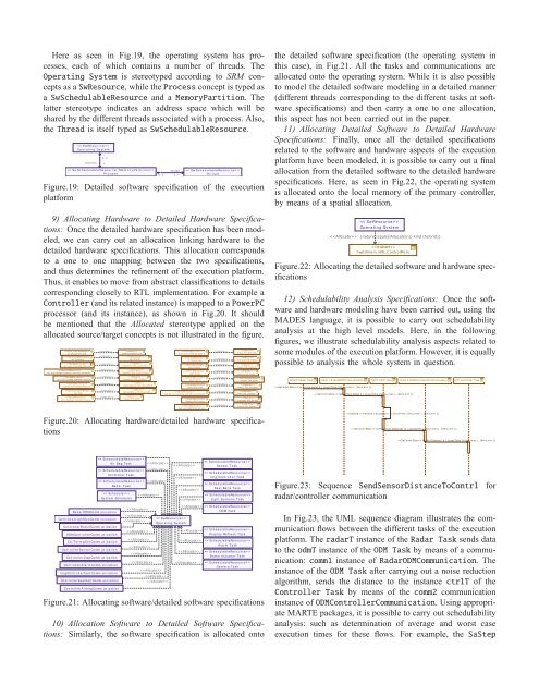
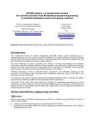
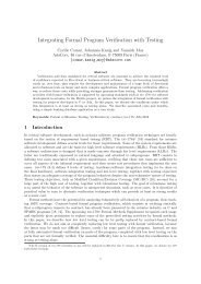
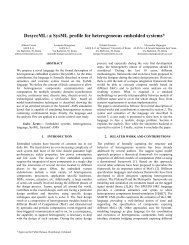
Here as seen in Fig.19, the operating system has processes,each of which contains a number of threads. TheOperating System is stereotyped according to SRM conceptsas aSwResource, while theProcess concept is typed asaSwSchedulableResource and aMemoryPartition. Thelatter stereotype indicates an address space which will beshared by the different threads associated with a process. Also,theThread is itself typed asSwSchedulableResource. >Op e r a t i n g Sy s t e mproc es s0 ..1* >Pr o c e s s0 ..1thread1 ..* >Th r e a dFigure.19: Detailed software specification of the executionplat<strong>for</strong>m9) Allocating Hardware to Detailed Hardware Specifications:Once the detailed hardware specification has been modeled,we can carry out an allocation linking hardware to thedetailed hardware specifications. This allocation correspondsto a one to one mapping between the two specifications,and thus determines the refinement of the execution plat<strong>for</strong>m.Thus, it enables to move from abstract classifications to detailscorresponding closely to RTL implementation. For example aController (and its related instance) is mapped to aPowerPCprocessor (and its instance), as shown in Fig.20. It shouldbe mentioned that the Allocated stereotype applied on theallocated source/target concepts is not illustrated in the figure.sys clk:System Clockctrl:Controllerctrl m em :Controller Mem oryim g proc:Im age Process or Secondar Controllerim g m em :Im age Process or Mem oryshared m em :Shared Mem orycan:CANodm :Obstacle Detection Modulehwclk:HardwareClockppc:PowerPChwctrlm em :HW_ControlMemhwim gctrl:HW_Im gControllerhwim gm em :HW_Im gMemhwsharedm em :HW_SharedMemhwchann elbox:HW_Chann elBoxhwodm :HW_ODMbraking sys:Braking Systemair bag:Air bagcam :Cam eraradar:Radaralarm :Alarmbelts:Seat beltsligh-sig sys:Lightning and Signaling Systemdisplay:HUD Displayhwbss :HW_BrakeSyshwairbag:HW_AirBaghwcam :HW_Cam erahwradar:HW_Radarhwalarm :HW_Alarmhwbelts:HW_SeatBeltshwlss :HW_LightSyshwdisplay:HW_Displaythe detailed software specification (the operating system inthis case), in Fig.21. All the tasks and communications a<strong>real</strong>located onto the operating system. While it is also possibleto model the detailed software modeling in a detailed manner(different threads corresponding to the different tasks at softwarespecifications) and then carry a one to one allocation,this aspect has not been carried out in the paper.11) Allocating Detailed Software to Detailed HardwareSpecifications: Finally, once all the detailed specificationsrelated to the software and hardware aspects of the executionplat<strong>for</strong>m have been modeled, it is possible to carry out a finalallocation from the detailed software to the detailed hardwarespecifications. Here, as seen in Fig.22, the operating systemis allocated onto the local memory of the primary controller,by means of a spatial allocation. >Op e r a t i n g Sy s t e m {nature (spatialAllocation), kind (hybrid)}hwctrlm em :HW_ControlMemFigure.22: Allocating the detailed software and hardware specifications12) Schedulability Analysis Specifications: Once the softwareand hardware modeling have been carried out, using theMADES language, it is possible to carry out schedulabilityanalysis at the <strong>high</strong> <strong>level</strong> models. Here, in the followingfigures, we illustrate schedulability analysis aspects related tosome modules of the execution plat<strong>for</strong>m. However, it is equallypossible to analysis the whole system in question.radarT:Radar Taskcomm 1:RadarODMComm un ication send raw data( d ) {execTim e (10 m s,m ax) , (8m s,m in )}odm T:ODM Task Notify Raw Data( d ) {execTim e (10 m s,m ax) , (8m s,m in )}comm 2:ODMControllerComm un icationctrlT:Controller Taskadd sens:Add itional Sensorshwsens:HW_SensorsFigure.20: Allocating hardware/detailed hardware specifications Per<strong>for</strong>m Calculation( ) {execTim e (3m s,m ax) , (2m s,m in )} send sensor distance( d ) {execTim e (10ms,m ax) , (8m s,m in )} Notify Distance( d ) {execTim e (10 m s,m ax) , (8m s,m in )} >A i r Ba g Ta s k > Co n t r o ll e r Ta s k > Ra d a r Ta s k >Sy s t e m Sc h e d u l e r >Se n s o r Ta s k > I m g Co n t r o ll e r Ta s k >Se a t Be l t s Ta s k > Li g h t Sy s t e m s Ta s kFigure.23: Sequence SendSensorDistanceToContrl <strong>for</strong>radar/controller communicationRa d a r ODMCo mm un i c a t i o nCo n t r o ll e r Li g h t Sy s Co mm un i c a t i o nCo n t r o ll e r Br a k e Co mm un i c a t i o nODMCo n t r o ll e r Co mm un i c a t i o nCt r l To I m g Ct r l Co mm un i c a t i o nCo n t r o ll e r Se n s o r Co mm un i c a t i o nCo n t r o ll e r Di s p Co mm un i c a t i o nCo n t r o ll e r A l a r m Co mm un i c a t i o nI m g Co n t r o ll e r Ca m Co mm un i c a t i o nCo n t r o ll e r Se a t b e l t Co mm un i c a t i o nCo n t r o ll e r A i r b a g Co mm un i c a t i o n >Op e r a t i n g Sy s t e m >ODM Ta s k >Di s p l a y Re f r e s h Ta s k >A l a r m Ta s k >Br a k e A c t u a t o r Ta s k >Ca m e r a Ta s kFigure.21: Allocating software/detailed software specifications10) Allocation Software to Detailed Software Specifications:Similarly, the software specification is allocated ontoIn Fig.23, the UML sequence diagram illustrates the communicationflows between the different tasks of the executionplat<strong>for</strong>m. TheradarT instance of theRadar Task sends datato theodmT instance of theODM Task by means of a communication:comm1instance ofRadarODMCommunication. Theinstance of theODM Task after carrying out a noise reductionalgorithm, sends the distance to the instancectrlT of theController Task by means of thecomm2 communicationinstance ofODMControllerCommunication. Using appropriate<strong>MARTE</strong> packages, it is possible to carry out schedulabilityanalysis: such as determination of average and worst caseexecution <strong>time</strong>s <strong>for</strong> these flows. For example, the SaStep