A SysML/MARTE high level methodology for real-time - Embedded ...
A SysML/MARTE high level methodology for real-time - Embedded ...
A SysML/MARTE high level methodology for real-time - Embedded ...

Create successful ePaper yourself
Turn your PDF publications into a flip-book with our unique Google optimized e-Paper software.
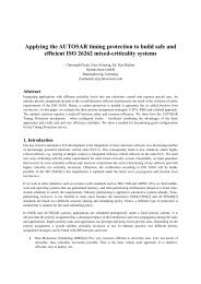
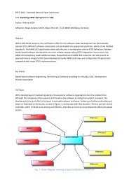
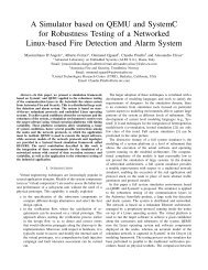
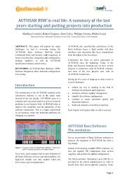
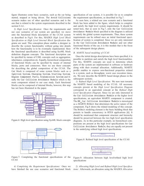
figure illustrates some basic scenarios, such as the car beingstarted, stopped or being driven. The Avoid Collisionsscenario makes use of other specified scenarios and is theone that is related to the system requirements described in thesection.V-A1.3) High Level Specification: Once the requirements anduse case scenarios of our system are specified; we moveonto the functional block description of the CCAS systemas described in Fig.6. For this, MADES High Level BlockSpecification or High Level Internal Block Specification diagramsare used. This conception phase enables a designer todescribe the system functionality without going into detailshow the functionality is to be eventually implemented. Herethe functional specification is described using <strong>SysML</strong> blockdefinition diagram concepts. The functional description canbe specified by means of UML concepts such as aggregation,inheritance, composition etc. Equally, hierarchical compositionof functional blocks can be specified by means of internalblocks, ports and connectors. Here we use these concepts<strong>for</strong> describing the global composition of the CCAS. TheCar block is composed of some system blocks such as aIgnition System,Charging System,Starting System,Engine Component Parts,Transmission System and finallytheCar Collision Avoidance Module which is themain component related to our case study. Each functionalblocks can be composed of internal blocks, however, this stephas not been illustrated in the paper. >A i r Co n d i t i o n e r Sy s t e m >El e c t r i c Su pp l y Sy s t e m >A u d i o / Vi d e o Mu l t i m e d i a De v i c e s >Ch a r g i n g Sy s t e m >Ga u g e s a n d Me t e r s >I g n i t i o n Sy s t e m >Sw i t c h e s >St a r t i n g Sy s t e m >Doo r s12 ..*110 ..10 ..10 ..10 ..10 ..11 ..*0 ..110 ..11 0 ..10 ..1 0 ..10 ..1 0 ..10 ..10 ..10 ..10 ..11111 >W i n d o w s >Ca r >10 ..1110 ..10 ..1 1En g i n e Coo li n g Sy s t e mW h ee l a n d Ti r e Pa r t s1111 > >En g i n e Co m p o n e n t Pa r t s >Ca r Co lli s i o n A v o i d a n c e Mo d u l e >W i r i n g Ha r n e ss e sSu s p e n s i o n a n d St ee r i n g Sy s t e m > >Tr a n s m i ss i o n Sy s t e m >Ex h a u s t Sy s t e m > >Fu e l Su pp l y Sy s t e mEn g i n e Oil Sy s t e mFigure.6: High <strong>level</strong> specification using <strong>SysML</strong> block conceptsGl o b a l Co lli s i o n A v o i d a n c e St r a t e g yDetect Colli sion by m eans of theinstalled radar detection or by theim age track ing sy stem . Switchingbetwee n radar and im age track ingdepending upon user requirem ents andweather conditions. Tak e app ropriateactions to av oid colli sions and notifythe driv erA v o i d Co lli s i o n sspecification of our system, it is possible <strong>for</strong> us to completethe requirement specifications, as described in Fig.7.As seen here, a related use case scenario and a functionalblock has been added to the figure, which helps to completeand satisfy the <strong>high</strong> <strong>level</strong> system requirements. It should benoted here, that as seen in Fig.7, only theCar CollisionAvoidance Module block specified in the diagram is utilizedto satisfy the global system requirements. Thus, these systemrequirements can be refined once an initial functional specificationof system is completed. Since we are only interestedin the Car Collision Avoidance Module and not otherfunctional blocks of the car, it is this module that is the focusof the subsequent design phases.B. <strong>MARTE</strong> based modeling of CCASOnce the initial design descriptions have been specified, it ispossible to partition and enrich the <strong>high</strong> <strong>level</strong> functionalities.For this, <strong>MARTE</strong> concepts are used to determine whichparts of the system are implemented in software or hardwa<strong>real</strong>ong with their eventual allocation. Additionally, <strong>MARTE</strong>profile enables to express non-functional properties relatedto a system, such as throughput, worst case execution <strong>time</strong>s,etc. We now describe the <strong>MARTE</strong> based design phases in thesubsequent sections.1) Refined High Level Specification: We now turn towardsthe <strong>MARTE</strong> based modeling of the CCAS. All necessaryconcepts present at the High Level Specification Diagramcorrespond to an equivalent concept at the Refined HighLevel Specification Diagram. Since we are only interested intheCar Collision Avoidance Module at the <strong>high</strong>er <strong>level</strong>specifications, an equivalent <strong>MARTE</strong> component is created.TheRH Car Collision Avoidance Module is stereotypedas a <strong>MARTE</strong>RtUnit that determines the active nature of thecomponent. Fig.8 shows the related modeling of this concept.TheRtUnit modeling element is the basic building block thatpermits to handle concurrency in RTES applications [6]. Itshould be mentioned that component structure and hierarchyshould be preserved between the two <strong>high</strong> <strong>level</strong> specificationdiagrams. As in this particular example, no hierarchical compositionsare present at the <strong>high</strong> <strong>level</strong> specifications <strong>for</strong>CarCollision Avoidance Module, they are equally not presentin the underlying refined <strong>high</strong> <strong>level</strong> specifications. >RH_ Ca r Co lli s i o n A v o i d a n c e Mo d u l eI mm i n e n t Co lli s i o n St r a t e g yA dd i t i o n a l Ti m i n g r e q u i r e m e n t s Ne a r Co lli s i o n A v o i d a n c e St r a t e g yCh a n g i n g La n e s St r a t e g yFigure.8: Refined <strong>high</strong> <strong>level</strong> specification of the CCASWhen ex ternal obj ect is less than 2m eters away , the driv er should benotified by an alarm and HUD, andsy stem should switch to a criticalwarning state. I f the sy stem rem ains incritical warning state f or m ore than 300m s and distance f rom obj ect is still lessthan 2 m eters then the engine should bestopp ed, brak es should be app lied,seatbelts should be tensioned and airbag should be deploy ed. The brak esshould be app lied f or 100 m sThe radar or the im age track ingm odule should send the data to theController ev ery 100 m s v ia thesy stem bus and the comm un icationshould tak e 20 m s, during whichthe bus should be busy . I n case ofimm inent colli sion, the controllershould send the brak e comm andwhich should tak e no m ore than 20m sWhen ex ternal obj ect is less than 3m eters away , the controller shouldswi tch to a warning state. I f the sy stemrem ains in this state f or 300 m s, thenthe driv er should b e notified v ia analarm and HUD, norm al b rak es shouldbe app lied <strong>for</strong> 10 m s f or reducing carspee d. Hazard warning lights should beactiv ated in the HUD.When the driv er is about tochange lanes or if the cardev iates f rom the curr entlane intentionally , the driv ershould b e notified v ia theHUD. I f the driv er is chaninglanes him self, the car turnsignal should be on >Ca r Co lli s i o n A v o i d a n c e Mo d u l e {kind (hybrid), nature (spatialAllocation)} >Ca r Co lli s i o n A v o i d a n c e Mo d u l eFigure.7: Completing the functional specifications of theCCAS >RH_ Ca r Co lli s i o n A v o i d a n c e Mo d u l eFigure.9: Allocation between <strong>high</strong> <strong>level</strong>/refined <strong>high</strong> <strong>level</strong>specifications4) Completing the Requirement Specifications: Once wehave finished the use case scenarios and functional block2) Allocating High Level and Refined High Level Specifications:Afterwards, an allocation using the MADES Allocation