Avionic-X: A demonstrator for the Next Generation Launcher Avionics
Avionic-X: A demonstrator for the Next Generation Launcher Avionics
Avionic-X: A demonstrator for the Next Generation Launcher Avionics

Create successful ePaper yourself
Turn your PDF publications into a flip-book with our unique Google optimized e-Paper software.
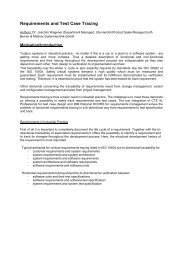
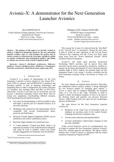
3 Distributed Dependable Architectures <strong>for</strong> Safety-Critical Applications4 With <strong>the</strong> help of <strong>the</strong> Swedish company ÅAC Microtec.• SPA (Space Plug-and-Play <strong>Avionic</strong>s),• SAVOIR,• DDASCA.SPA was developed in United States by <strong>the</strong> Air ForceResearch Laboratory (AFRL) 4 . The draft SPA standard hasalready been released through <strong>the</strong> American Institute ofAeronautics and Astronautics (AIAA). The SPA ef<strong>for</strong>t is aresponse to <strong>the</strong> need <strong>for</strong> reduced design, fabrication,integration, and test schedules (and <strong>the</strong>re<strong>for</strong>e relatedengineering costs) <strong>for</strong> small spacecraft, thanks to selfconfigurationand self-organization.SAVOIR stands <strong>for</strong> Space <strong>Avionic</strong>s Open InterfaceArchitecture. The space industry and Agencies have recognizedthis already <strong>for</strong> quite some time: The level of standardization in<strong>the</strong> spacecraft avionics systems should be raised in order toFigure 1. Context of <strong>the</strong> <strong>Avionic</strong>-X projectincrease efficiency and reduce development cost and schedule.It has been proposed to federate several ongoing initiativesActually <strong>the</strong>re are several o<strong>the</strong>r ESA technology programs under <strong>the</strong> common “Space <strong>Avionic</strong>s Open Interfacebesides FLPP which include avionics aspects, <strong>for</strong> instance: Architecture” initiative. Within this initiative, <strong>the</strong> approach• Basic Technology Research Programs (TRP) <strong>for</strong> TRLbased on reference architectures and building blocks plays afrom 1 to 3. In particular ESA’s Deep Sub-Micronkey role. The SAVOIR Advisory Group (SAG) membersinitiative is working with industry to design a newregroups space agencies, large and small system integrators andgeneration of space-worthy microchips;equipment/software suppliers.Lastly, DDASCA is a newly born consortium dedicated to• General Support Technology Programs (GSTP) <strong>for</strong>TRL from 2 to 8.Distributed Dependable Architectures <strong>for</strong> Safety-CriticalApplications. It regroups universities and research centers,Besides, <strong>the</strong> Launch Vehicle (LV) avionics sector is toosmall a market to allow <strong>for</strong> self-standardization and to fundsystem integrators and equipment/software suppliers, withstandardization organisms.specific technologies development. The “Not Invented Here”syndrome is not an option. There<strong>for</strong>e we have to seek ideas andIt aims at engineering and standardizing referencetechnologies in o<strong>the</strong>r innovative sectors, and establish a spinin,ra<strong>the</strong>r than recreate everything from scratch.architectures with generic building blocks, that will bemodular, provable, reusable and safe, to build hardware andsoftware plat<strong>for</strong>ms <strong>for</strong> safety-critical applications (DAL A –Several trends from outside <strong>the</strong> Launch Vehicle (LV) sectorseem promising:SIL 4).Within <strong>the</strong> <strong>Avionic</strong>-X project frame, we will strive to take• The “More Electric Aircraft” trend in aeronautics. Ona launcher, this could translate into electromechanicalactuators (EMA) <strong>for</strong> Thrust Vector Control, andelectrical valves in cryotechnic engines, thus givingbirth of a “More Electric <strong>Launcher</strong>”.in a wide range of promising concepts, emerging standards andinnovations (with a TRL above 2), and per<strong>for</strong>m trade-offanalysis w.r.t. <strong>the</strong>ir interest in a launcher system context, andfinally prototype and test <strong>the</strong> most interesting candidates on <strong>the</strong>plat<strong>for</strong>m.• Standardization is a trend in <strong>the</strong> satellite industry with<strong>the</strong> Space Plug-and-Play Architecture (SPA), <strong>the</strong>III. AVIONIC-X WORK LOGICSAVOIR 2 initiative, and more generally <strong>for</strong> embeddedsystems with <strong>the</strong> DDASCA 3 consortium. This couldA. Work Logic presentationalso encompass <strong>the</strong> IMA concepts (Integrated Modular <strong>Avionic</strong>-X project is more than a plat<strong>for</strong>m or a list of<strong>Avionic</strong>s), and <strong>the</strong> ARINC 653 Time and Space technologies. Its work logic is built on three axes:partitioning (TSP) standard [3]. Several projects arecurrently trying to spin-in from <strong>the</strong> aeronautical• #1 - Demonstrator activities (target IRL-3),domain <strong>the</strong> TSP/IMA technology <strong>for</strong> space • #2 - Technological activities (target TRL-6),applications.• #3 - <strong>Launcher</strong> avionics engineering.Three of <strong>the</strong> ongoing initiatives leading towards morestandardization in avionics, with reference architectures and As shown on <strong>the</strong> figure hereafter, <strong>the</strong>se three branches ofbuilding blocks, are presented hereafter:<strong>Avionic</strong>-X interact all along <strong>the</strong> project in order to reach ourtargets in terms of TRL and IRL.2 Space AVionics Open Interface Architecture
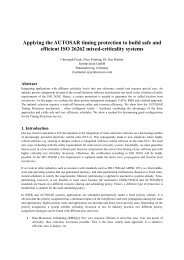
The needs <strong>for</strong> demonstrations arise equally from <strong>the</strong>oreticalstudies on various launcher avionics architectures (“SEL-X”activities) in a top-down approach, and from technologicalenablers studies in a bottom-up approach. The “technologicalbranch” also focuses on innovative methods with <strong>the</strong> same goalin mind: reducing <strong>the</strong> Total Cost of Ownership (TCO) of <strong>the</strong>launcher system.The project <strong>Avionic</strong>-X is currently in phase A (systemconcepts feasibility). It is due to pursue its phase B(specification and preliminary design) from <strong>the</strong> beginning of2012, with an incremental development cycle, similar to <strong>the</strong>“spiral model” common in software engineering. This willoffer several windows of opportunity to introduce newtechnologies and new partners in <strong>the</strong> project.Figure 2. Work Logic of <strong>the</strong> <strong>Avionic</strong>-X projectB. <strong>Launcher</strong> avionics engineering (“SEL-X”)This activity branch of <strong>the</strong> project aims at identifying <strong>the</strong>key drivers and requirements <strong>for</strong> a launcher avionics system,and following a top-down approach, taking into account <strong>the</strong>technological candidates, in order to propose several possibleavionics architectures (named “SEL-X”), and assess <strong>the</strong>irper<strong>for</strong>mances and cost.But first, to prepare <strong>the</strong> future, we have to look back at<strong>the</strong> past. So let’s take a look at <strong>the</strong> Ariane 5 launcher family.Ariane 5 avionics (see figure 3) follows three main drivers: Itis a duplex system, it is organized in several sub-systems(Flight Control, Telemetry, Electrical Power and FlightSafety Sub-Systems), and it is also strongly constrained by<strong>the</strong> rule of “geographical return” (which may have led to apractical but non-optimal architecture).Ariane 5 avionics has evolved since <strong>the</strong> beginning ofAriane 5 program, in order to solve obsolescence problemsor to accommodate <strong>the</strong> various versions of <strong>the</strong> launcher, butits duplex architecture stays essentially <strong>the</strong> same. The duplexchoice was not derived from system requirements but wasseen as a way to increase robustness and ensure reliability.Figure 3. Overview of Ariane 5 upper composite avionics architectureAriane 5 avionics system breakdown in sub-systems willnot necessarily be retained, and <strong>for</strong> <strong>the</strong> moment,geographical return constraints should be put aside, in orderto look <strong>for</strong> “more” optimal solutions.The trade-offs per<strong>for</strong>med on <strong>the</strong> SEL-X architectures ledus to consider several potential improvements: First, astronger integration (in order to reduce <strong>the</strong> number ofequipments, and <strong>the</strong> recurring costs), with standard modules
in a rack-based architecture (following <strong>the</strong> IMA trend) anduse of Time and Space Partitioning; second, a hotredundancy concept, and a communication based on a timetriggeredprotocol (see § III.C.1)).1) Toward a more integrated architecture (IMA)A “centralized” architecture is an architecture where <strong>the</strong>main tasks are executed on <strong>the</strong> same processing unit. In a“distributed” architecture, <strong>the</strong> tasks are distributed throughseveral equipments.The current Ariane 5 avionic architecture is mainlycentralized, as <strong>the</strong>re is an On-Board Computer (OBC)centralizing all <strong>the</strong> sensor data to compute <strong>the</strong> GNC and <strong>the</strong>sequential algorithms <strong>for</strong> commanding <strong>the</strong> launcher.However it is also partially distributed as o<strong>the</strong>r equipmentsalso have “intelligent” functions to per<strong>for</strong>m, be<strong>for</strong>e or after<strong>the</strong> OBC computations. The architecture is organized on a“master-slave” mode, meaning that <strong>the</strong> centralized OBCtakes all <strong>the</strong> decisions, based on <strong>the</strong> sensor inputs andmeasurements. This was a way to ensure <strong>the</strong> determinismrequired <strong>for</strong> a high level of reliability and availability.The choice of Ariane 5 was <strong>the</strong> result of a top-downallocation of <strong>the</strong> main avionics functions to differentequipments, with clear industrial perimeters andresponsibilities, accepting <strong>the</strong> fact that each industrial wouldprobably have to develop or to implement computing meansin an heterogeneous way and without any harmonization.In general this was not a problem as most of <strong>the</strong>equipments only needed very simple functions, easy toimplement within simple components such as DSP, ASIC orFPGA. But <strong>for</strong> complex equipments like <strong>the</strong> SRI (InertialMeasurement Unit), <strong>the</strong> computing unit could have beenharmonized or merged with <strong>the</strong> OBC itself.Today, <strong>the</strong> evolution of CPU capacity allows us toenvision a stronger centralization (or integration) of <strong>the</strong>architecture, <strong>for</strong> example by merging <strong>the</strong> SRI and OBCnumerical calculations on <strong>the</strong> same computing node, in orderto reduce <strong>the</strong> number of equipments and <strong>the</strong> associatedweight.We reach here <strong>the</strong> concept of Integrated Modular<strong>Avionic</strong>s, which comes from Aircraft development. Themain idea is to reduce <strong>the</strong> amount of embedded avionichardware by sharing <strong>the</strong> same hardware and softwareresources between various sub-systems. In this concept, astandardized CPU modules would allow to reuse <strong>the</strong> samemodule <strong>for</strong> all <strong>the</strong> launchers functions requiring computingcapabilities.This standard Processing Module would be physicallyregrouped with o<strong>the</strong>r standardized or specific modules inracks, as it has been done in <strong>the</strong> satellite industry (<strong>for</strong>example <strong>the</strong> Spacebus 4000 avionics concept described in[5]). Within <strong>Avionic</strong>-X we call this standard ProcessingModule “MDHB-X”, which stands <strong>for</strong> “Modular DataHandling Block” and is presented in § C.2).Modular Data Handling Block(MDHB-X)Power BoardEMPTYInertial BoardGNSS BoardFigure 4. Example of a rack-based architecture2) Redundancy conceptThe current Ariane 5 system is based on a duplexarchitecture composed of two onboard computers in hotredundancy. The nominal one is in charge of all operationson both avionics chains and <strong>the</strong> redundant one only spies asubset of <strong>the</strong> 1553 messages to maintain its own flightcontext. In case of auto-detected errors on <strong>the</strong> nominal OBC,an error signal is sent and a hand-over is done to <strong>the</strong>redundant OBC which takes <strong>the</strong> control of <strong>the</strong> 1553 busesand continues <strong>the</strong> mission. The redundant OBC becomes“<strong>the</strong> last survivor” and <strong>the</strong> nominal OBC cannot recover <strong>the</strong>flight control.The first redundancy concept which we aim at testing on<strong>Avionic</strong>-X is not dissimilar to Ariane 5’s one, but improves<strong>the</strong> transition phase and simplifies <strong>the</strong> design of <strong>the</strong> flightsoftware. As a matter of fact, in this concept both OBCsexecute <strong>the</strong> same software in parallel, and <strong>the</strong> selection of <strong>the</strong>command which shall be executed is per<strong>for</strong>med by <strong>the</strong>actuator. The failure of one OBC is <strong>the</strong>n almost transparent,hence a true “hot redundancy”. The reinsertion of <strong>the</strong> faultyOBC could also be envisioned, in case of a transient failurefollowed by a reset and successful auto-tests.This concept of “selection by <strong>the</strong> actuator” couldeventually be scalable to a triplex concept, <strong>for</strong> specificmissions where <strong>the</strong> exposition to natural radiativeenvironment could o<strong>the</strong>rwise lead to unacceptableunreliability figures.C. Technological enablersThe second activity branch of <strong>the</strong> project aims atidentifying innovative technological candidates (hardware,software, methods), per<strong>for</strong>ming trade-offs and feasibilitystudies w.r.t. a launcher system, and elaborating roadmaps tomature <strong>the</strong> relevant technological enablers up to TRL 6.The technologies we are looking at in <strong>the</strong> frame of <strong>the</strong><strong>Avionic</strong>-X shall cover <strong>the</strong> biggest part of a launcher avionics
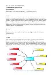
functional needs. At this stage of <strong>the</strong> project, all trade-offsare not completed yet, so we will detail only a few of <strong>the</strong>mhereafter, focusing on ERTS² targets:1) Communication SystemThe Communication system, which is <strong>the</strong> “backbone” of<strong>the</strong> digital system, comes naturally first, as it will support <strong>the</strong>integration of every o<strong>the</strong>r building blocks on <strong>the</strong><strong>demonstrator</strong> in <strong>the</strong> next increments.This work package has included several trade-offs, w.r.t.bus technology (optical, cable, wireless…), bus topology(star, ring…), communication protocols, field buses.Moreover, it appears interesting to follow <strong>the</strong> evolution incommunication systems from a message-centric model to adata-centric design. In a message-centric architecture, <strong>the</strong>communication system does not recognize <strong>the</strong> dataembedded in <strong>the</strong> messages it carries. In opposition, a datacentricdesign could be represented as a global virtualdatabase, with applications accessing it without worryingabout <strong>the</strong> distributed aspect of <strong>the</strong> system. The “smartTelemetry” concepts follow this data-centric design too. Forexample, a sensor may acquire data at 100Hz, but onlyupdating <strong>the</strong> virtualized data when <strong>the</strong> change is bigger thana predefined limit, thus avoiding bottleneck points in <strong>the</strong>communication system.The communication system has to answer to criteriadefined by <strong>the</strong> architecture of <strong>the</strong> new launcher. The firstSEL-X studies identified <strong>the</strong> following targets:• At least 50 or 100 times <strong>the</strong> Ariane 5 communicationsystem throughput in order to fit <strong>the</strong> necessaryincrease of command/control data flow due to <strong>the</strong>“hot” redundancy flight control concept suggested inSEL-X (see § B.2)), and moreover, to host <strong>the</strong>launcher telemetry data flow which is managed untilnow on Ariane 5 by a dedicated bus.• A better exchanges determinism, ensured as must aspossible at standard level, firstly to avoid a costlydevelopment of a “tailor-made” deterministic layerand also to simplify <strong>the</strong> hot redundancy managementand synchronization between <strong>the</strong> communicationsystem nodes.• Reduce <strong>the</strong> communication system harness weight,• Reduce <strong>the</strong> electric consumption,• Increase Communication System flexibility.The current state of <strong>the</strong> preliminary design includes atleast three main communication systems on <strong>the</strong><strong>demonstrator</strong>:• One copper bus with a time-triggered E<strong>the</strong>rnetcommunication, <strong>for</strong> example TTE<strong>the</strong>rnet. With athroughput of 100 Mbits/s (possible 1Gbits/s) basedon E<strong>the</strong>rnet (LAN compatible), TTE<strong>the</strong>rnet managesdeterminism at standard level by offering TimeTriggered services based on PTP IEEE 1588protocol, <strong>the</strong> TT messages. This standard also takesinto account Rate-constrained (RC) messages likeARINC664 (AFDX) and is also compliant with basicE<strong>the</strong>rnet messages, called Best Ef<strong>for</strong>t (BE) in <strong>the</strong>standard. It benefits from <strong>the</strong> long E<strong>the</strong>rnetexperience, tools and has already been chosen inspace projects. Here is a purely <strong>the</strong>oretical viewillustrating <strong>the</strong> three kinds of messages managed by<strong>the</strong> TTE<strong>the</strong>rnet standard:Figure 5. Different kinds of TTE<strong>the</strong>rnet traffic• One optical bus, <strong>for</strong> example FibreChannel. Themain benefits of using optical fiber at physical levelare an increased bandwidth and an immunity toElectromagnetic Interference (EMI). Thus, <strong>the</strong>harness weight could decrease due to wires shieldingreduction and <strong>the</strong> uselessness of EMC filters at boardlevel. Moreover, FibreChannel has been crafted toeasily map o<strong>the</strong>r protocols, so that existing softwarewritten <strong>for</strong> legacy protocols can be easily ported.Determinism and fault tolerance may be mapped toFibre Channel. It is compatible with 1553 (butwithout <strong>the</strong> limitations of <strong>the</strong> MIL-STD-1553standard in terms of throughput, message size,…)and it offers a low latency network.• One MIL-STD-1553 bus, which would ease <strong>the</strong>connection of existing equipments on <strong>the</strong><strong>demonstrator</strong>. It offers industrial partners a wellknownspace bus to plug possible off-<strong>the</strong>-shelfdemonstrations using this standard.2) Modular Data Handling Block (MDHB-X)In this branch of <strong>the</strong> <strong>Avionic</strong>-X project, we will defineand demonstrate <strong>the</strong> MDHB-X solution <strong>for</strong> data processingand communication bus interface (such as identified in§ B.1)), while following several trends:• IMA and TSP <strong>for</strong> space applications;• Multi-core architectures.IMA changes drastically <strong>the</strong> usual industrial way ofworking: Sub-system suppliers are no longer <strong>the</strong> suppliers of<strong>the</strong> avionics part of <strong>the</strong>ir sub-system (that would be genericbricks), and could perhaps become only “applicationsoftware providers”.As <strong>for</strong> <strong>the</strong> multi-core aspects, we have to prepare <strong>the</strong> useof multi-core processors in space systems. Multi-corearchitecture is a solution to introduce additional processingpower, to improve <strong>the</strong> fault detection isolation and recovery(FDIR), and finally to implement more easily time and spacepartitioning.
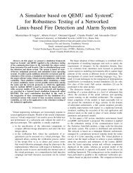
Taking this into account, we will define and demonstratea generic processing and Input/Output module answeringdifferent needs <strong>for</strong> data handling in a launcher. This“Modular Data Handling Block <strong>for</strong> <strong>Avionic</strong>-X”, orMDHB-X, is presented on <strong>the</strong> figure below.Figure 6. Modular Data Handling Block <strong>for</strong> <strong>Avionic</strong>-X (MDHB-X)The Modular Data Handling Block (MDHB-X) aims atproviding a generic, versatile and configurable computingsystem solution. Each MDHB-X unit can be made of variouspredefined combinations of Processing Modules (PM) andI/O Modules (IOM). Through this mechanism, it is possibleto create a wide range of MDHB-X units thanks to PM andIOM generic building blocks.Here are shown some configurations of <strong>the</strong> MDHB-X:Centralised highprocessingneed:ProcessingModule #1ProcessingModule #2Non-intelligent Remote-Terminal Unit:BasicSensorsCondition.unitSmartSensorsNon-intelligentActuatorsSeveral candidates are <strong>for</strong>eseen to be assessed asprocessor, like <strong>the</strong> LEON4-based NGMP plat<strong>for</strong>m, or someARM implementation, both potentially in single or dual coreconfiguration. The IOM will lie on a custom FPGA solution.The different I/Os to handle include <strong>for</strong> instance <strong>the</strong>communication system and sensors (“intelligent” or not, andaccessed through conditioner unit or directly).Each Module of MDHB-X units will lie on a separateboard, and <strong>the</strong> integration could be done thanks to a rack,connecting <strong>the</strong>m toge<strong>the</strong>r through a backplane bus <strong>for</strong>example.From a software point-of-view, <strong>the</strong> spaceflight field is on<strong>the</strong> verge of an evolution from federated avionics and datahandling architectures to Integrated Modular <strong>Avionic</strong>s (IMA)paradigm, as it happened a few years ago with airbornesystems. By allowing running several previously segregatedpieces of software on <strong>the</strong> same computing plat<strong>for</strong>m, IMA inspace applications is expected to have an impact on <strong>the</strong>overall avionics’ mass, volume, power consumption andrecurrent cost.As <strong>the</strong> physical boundaries of federated subsystemsdisappear, IMA has to implement a new kind of separationbetween <strong>the</strong> different pieces of software involved, through<strong>the</strong> technique of partitioning.In <strong>the</strong> frame of <strong>Avionic</strong>-X <strong>demonstrator</strong>, <strong>the</strong> Middlewarelayer represents every piece of software between <strong>the</strong> barehardware and <strong>the</strong> applicative software, including <strong>the</strong>partitioning layer (inside or outside <strong>the</strong> RTOS) and <strong>the</strong> OS.Here is a scheme of <strong>the</strong> Middleware in <strong>Avionic</strong>-X:I/OsVirtualizationCPU /FPUMMURedundancyServicesBasic APServicesRTOS#1Partition 1APIH/W OBTPowerI/O ModulePowerI/O ModuleH/WPartition 2<strong>Avionic</strong> Communication SystemPowerI/O ModuleI/Os I/FI/ODriversI/O FrameManagementServicesI/OVirtualizationServicesI/O ModuleNetworks gateway:H/WAutotestsMiddleWareI/O PartitionFigure 7. Various configurations of <strong>the</strong> MDHB-XFigure 8. Middleware in <strong>Avionic</strong>-X
In partitioning-based software, like in ARINC-653systems <strong>for</strong> instance, isolation, protection and determinismlie on <strong>the</strong> concept of Time and Space Partitioning (TSP). Itallows a strong segregation of pieces of software of mixedcriticalities and/or mixed suppliers by implementing a staticallocation of fixed amounts of memory <strong>for</strong> each partition,and a fixed amount of CPU time allocation of each partitionaccording to a cyclic preemptive execution scheme. In thislight, <strong>the</strong> MDHB-X represents <strong>the</strong> physical implementationof IMA.Actually, <strong>the</strong> market offers a wide panel of partitioningsolutions, from bare metal hypervisors (or Virtual MachineMonitors) to userspace RTOSes over partitioningmicrokernels, and care must be taken when choosing asuitable option depending on <strong>the</strong> project. XtratuM hypervisoris currently <strong>for</strong>eseen, as well as in CNES and ESA studies.Ano<strong>the</strong>r <strong>for</strong>m of abstraction mechanism used in IMAsystem is <strong>the</strong> concept of Input/Output virtualization.This consists in presenting to every software instance <strong>the</strong>same abstracted and generic interface to manage I/Os byisolating high-level software and <strong>the</strong> communication system,having available each piece of data at each node of <strong>the</strong>system, solving equipment synchronization problematic,supplying data consistent with <strong>the</strong> equipment need (not only<strong>the</strong> last update), reading an entire engineering data like aquaternion (without update during acquisition) and ensuringdata consistency.The resulting generic layer will be usable on every pieceof equipment (i.e. MDHB-X).3) O<strong>the</strong>r technological enablersThe o<strong>the</strong>r work packages and technologies we arelooking at in <strong>the</strong> frame of <strong>the</strong> <strong>Avionic</strong>-X project are not fullydetailed in this paper, but <strong>the</strong>y encompass:• Flight Control:Within <strong>Avionic</strong>-X we will explore different inertialnavigation sensors (e.g. hemispherical resonator gyro orfiber-optics gyro), which would be less expensive than <strong>the</strong>gyrolaser technology used on Ariane 5. GNSS hybridizationwill also be considered, in order to improve <strong>the</strong> navigationprecision or to compensate <strong>for</strong> less precise gyros, and toprovide real-time localization <strong>for</strong> safeguard purposes.MEMS gyrometers distributed along <strong>the</strong> launcher will beconsidered in order to improve <strong>the</strong> robustness of ThrustVector Control. As a matter of fact, vibrating structuregyroscopes manufactured with MEMS technology havebecome quite inexpensive and widely available.• Pyrotechnics:Both opto-pyrotechnics and advanced electropyrotechnicswill be assessed during <strong>the</strong> <strong>Avionic</strong>-X project.• RF communications:In order to improve <strong>the</strong> RF links between <strong>the</strong> launcherand <strong>the</strong> ground means (higher bit rate with less energyconsumption), we will test and mature directive antennas,ei<strong>the</strong>r phased array antennas or active antennas on innovativematerials.• Power <strong>Generation</strong> and Distribution (Digital PowerControl);• Data acquisition and sensors;• Ground System – Onboard Interfaces (electrical andradiofrequency parts of <strong>the</strong> Ground to LaunchVehicle Interface);• EGSE and Simulators;• Harness and connectors, taking into account that <strong>the</strong>communication and power supply harness of atypical Launch Vehicle electrical system representmore than 10 kilometers of cable of various types !D. Methods: A focus on Model-Driven Engineering1) The MDE approachThe MDE approach is meant to increase productivity bymaximizing compatibility between systems (via reuse ofstandardized models), simplifying <strong>the</strong> process of design (viamodels of recurring design patterns in <strong>the</strong> applicationdomain), and promoting communication between individualsand teams working on <strong>the</strong> system (via a standardization of<strong>the</strong> terminology and <strong>the</strong> best practices used in <strong>the</strong> applicationdomain).MDE reduces costs, in particular hidden costs or costoverruns, not <strong>for</strong>eseen at <strong>the</strong> beginning of a software project.The famous “Chaos Report” (an industry study by <strong>the</strong>Standish Group) [1] is nowadays contested, however it foundthat <strong>for</strong> IT (in<strong>for</strong>mation technology) projects, <strong>the</strong> averagecost overrun was 43 percent, and 71 percent of projects wereover budget.Moreover, according to [4], available statistics on bugs inembedded systems show that approximately 75% of <strong>the</strong>m arecaused by ambiguities or misunderstandings between systemrequirements and software requirements. Moreover, sucherrors are generally found late in <strong>the</strong> project life, thus areparticularly expensive to correct 5 .In <strong>the</strong> frame of <strong>the</strong> European Project ASSERT (see [2]),it has been estimated that a gain of 10% is achievable interms of productivity during software engineering, due to:• <strong>the</strong> use of <strong>for</strong>mal modeling, proof and verification atsystem level,• data modeling and code generation techniques.5 Original citation in French: « Les statistiques disponibles […] sur lacause des bugs dans les systèmes embarqués montrent qu’environ 75% deceux-ci sont lies à des ambigüités ou des divergences de compréhensionentre spécifications systèmes et spécifications logicielles. Ce type de bugs apour circonstance aggravante d’être généralement trouvé très tard dans lesprojets et donc d’être particulièrement coûteux à corriger ».
The MDE covers <strong>the</strong> whole range from softwareintensivesystems to on-board code, and relies on <strong>the</strong> use ofvarious modeling languages, which are presented in § D.2).The following figure shows a typical development cycle<strong>for</strong> a space transportation system, using a MDE approach:Figure 9. Model-Driven Engineering process <strong>for</strong> a space transportation system2) Software intensive system EngineeringIn launchers systems, <strong>the</strong> role of <strong>the</strong> software is more andmore important in functional chains. Fur<strong>the</strong>rmore, on onehand <strong>the</strong> embedded software becomes more complex andharder to master. On <strong>the</strong> o<strong>the</strong>r hand, <strong>the</strong> introduction of IMA(Integrated Modular <strong>Avionic</strong>) principles in avionicsarchitecture implies new software rules: use of TSP (Timeand Space Partitioning), distributed software architecture...It is essential to ensure <strong>the</strong> consistency of <strong>the</strong> softwareengineering all over <strong>the</strong> system development. Ano<strong>the</strong>r veryimportant aspect is to limit <strong>the</strong> risk and anticipate <strong>the</strong>potential problems which could be faced during <strong>the</strong>development: early validation shall also be an objective. Tofulfill <strong>the</strong>se objectives, it has been decided, in <strong>the</strong> context of<strong>the</strong> <strong>Avionic</strong>-X project, to define a Model Driven Engineering(MDE) process to support <strong>the</strong> embedded softwaredevelopment.The advantages of using models can be presented asbelow:• Consistency improvement:oModels are more <strong>for</strong>mal than hand writtendocument (misunderstanding limitation),ooModels can be analysed to check developmentrules, to verify properties (softwareverification process improvement)...Model trans<strong>for</strong>mation using tools instead ofmanual trans<strong>for</strong>mation from documents.• Early validation:ooModels can be executed to verify behaviour of<strong>the</strong> system,Models can be used to ease <strong>the</strong> build ofvalidation tests.As shown in <strong>the</strong> ECSS-E-40 [6] following overview (seefigure 10), <strong>the</strong> planned MDE process will cover all <strong>the</strong>software development activities from <strong>the</strong> “software relatedsystem requirements process” to <strong>the</strong> “validation w.r.tTechnical Specification activity”. In addition to <strong>the</strong> followingfigure, ano<strong>the</strong>r activity is essential: <strong>the</strong> “System datarequirement” which consists in <strong>the</strong> management (all over of<strong>the</strong> system development) of all data exchanged between <strong>the</strong>different parts of <strong>the</strong> software intensive system.
Figure 10. Software engineering process overviewFor each activity, <strong>the</strong> following models are <strong>for</strong>eseen:• System data requirements:System related data model that will represent all<strong>the</strong> data and interfaces types in a common language(currently an extension of ASN1.0 is envisaged).This model is refined by all teams involved from<strong>the</strong>ir unit/dimension until <strong>the</strong>ir software interfaceimplementation (taking into account <strong>the</strong> differentlevel of implementation: equipment software,communication protocol, low level software,applicative software).• Software related system requirementsSoftware-intensive system SysML model whichdescribes <strong>the</strong> static architecture: definition offunctional blocks, interfaces (data flow and controlflow), mission data and <strong>the</strong> non algorithmicbehaviour: mode automata, time line, activationcondition, activation frequencies and acyclicactions… this model is independent of <strong>the</strong> chosensystem architecture (redundancy policy, processingunits …). It corresponds to <strong>the</strong> System SoftwareSpecification (SSS) in <strong>the</strong> ECSS wording.Interface requirement Document isautomatically generated from a refinement of <strong>the</strong>System related data model.Software-intensive system design model whichdescribes <strong>the</strong> processing units, <strong>the</strong> avioniccommunication means, <strong>the</strong> physical equipments, <strong>the</strong>software partitions, redundant equipments, dataflows and <strong>the</strong>ir associated latencies, <strong>the</strong> allocation offunctional blocks to partition, <strong>the</strong> partition allocationto processing units (AADL 6 is currently envisagedto describe this model). This model corresponds to apart of SRS in <strong>the</strong> ECSS-E-40 wording.6 AADL stands <strong>for</strong> “Architecture Analysis & Design Language”, but it isinteresting to remind that at <strong>the</strong> beginning, AADL stood <strong>for</strong> <strong>Avionic</strong>sArchitecture Description Language.• Software requirements & architectureSoftware static architecture model whichdescribes <strong>the</strong> static decomposition (in terms ofsoftware components/objects) of <strong>the</strong> software. Thismodel will use UML <strong>for</strong> manual code and Scade <strong>for</strong>code that will be automatically generated. Interfacesbetween <strong>the</strong> two <strong>for</strong>malisms will be ensured using <strong>the</strong>ASN1.0 language (and automatically generatedwrappers).Software-intensive system detailed design modelwhich is a refinement of <strong>the</strong> previous system designmodel. It contains <strong>the</strong> thread definition, subprograms(interfaces), data flow timing constraints, worst casetiming (bus and subprogram estimations).Interface Control Document is automaticallygenerated from a refinement of <strong>the</strong> System relateddata model.• Software design & implementationThe implementation will be made usingAutomatic Code <strong>Generation</strong> (ACG) <strong>for</strong> interfaces(code skeleton) from UML model, and Scade modelsare refined until containing all <strong>the</strong> functional aspects(to be able to generate a final flight code).• Validation & Verification related to implementationand modelsOne of <strong>the</strong> goals of all <strong>the</strong>se modelling activitiesis also to provide early validation and/or automaticreplay/generation of (early) validations activities.The following list is far from exhaustive:ooSoftware-intensive system SysML model: use ofsimulation with a system granularity.Automatic generation of validation tests fromsequence diagrams.Software intensive system detailed designmodel: automatic generation of on-boardsoftware scheduler (or configuration) and <strong>for</strong>numerical validation software, TSPconfiguration, verification of all <strong>the</strong> worst casetiming in<strong>for</strong>mation (data flow latencies, worstcase execution times …)o Software architecture models: automaticgeneration of integration tests.oSoftware design and implementation: unit test& coverage per<strong>for</strong>med at model level <strong>for</strong> Scademodels. Use of <strong>for</strong>mal proof (ADA 2012) toreplace some unit test <strong>for</strong> (suited) manual code.• Models consistencyThe <strong>Avionic</strong>-X models shall ensure someconsistency between <strong>the</strong>ir different views. Part of <strong>the</strong>work is made by <strong>the</strong> refinement of <strong>the</strong> data interfacesdefined in <strong>the</strong> system related data model. But it is farfrom sufficient.
Intra-model consistency will be verified usingOCL rules <strong>for</strong> AADL, UML, SysML models. Scademodels will be verified using in-house TCL scripts.Inter-model consistencies have many differentmeans to be verified. Most of <strong>the</strong>m will be assured byusing scripts which will import a version of <strong>the</strong>interface and data types. For instance, an Acceleoscript can be written in order to translate an ASN1.0data type in a UML/SysML/AADL data type.Then we have been fine-tuning <strong>the</strong> requirements andobjectives during <strong>the</strong> feasibility phase, and a first set of“plat<strong>for</strong>m means” has been written down, as shown on figure12, which gives an overview of <strong>the</strong> global concept of<strong>Avionic</strong>-X <strong>demonstrator</strong>.• O<strong>the</strong>rs ModelsIn parallel to <strong>the</strong>se models dedicated to on-boardsoftware development, <strong>the</strong> MDE activity in <strong>Avionic</strong>-X willalso cover following modelling: Data handling system withSystemC (data handling system specification: used <strong>for</strong>specification verification and simulator generation (<strong>for</strong>applicative software development support)); EquipmentSimulator Software Architecture using UML and ASN1.0interfaces (<strong>for</strong> functional closed loop validation of <strong>the</strong> onboardsoftware); Algorithm Prototyping Models using inhousecommon <strong>for</strong>malism (<strong>for</strong> a faster and safer translationof prototype to on-board software).Figure 12. Overview of <strong>the</strong> <strong>Avionic</strong>-X <strong>demonstrator</strong>IV.AVIONIC-X DEMONSTRATION PLATFORMThe last activity branch of <strong>the</strong> project shall cover allplat<strong>for</strong>m needs in order to be ready <strong>for</strong> <strong>the</strong> first test phase at<strong>the</strong> end of <strong>the</strong> first increment, and shall manage <strong>the</strong> various<strong>demonstrator</strong> configurations, deriving from <strong>the</strong> o<strong>the</strong>r twoactivity branches (SEL-X and technological enablers, seepart III).The key properties of this <strong>demonstrator</strong> are modularity,openness and connectivity. It will keep evolving, and will beable to host different demonstrations (unitary or integrated).The “virtual layer” (shown at <strong>the</strong> bottom of figure 11) and<strong>the</strong> simulators will allow several testing configuration, fromSWIL to HWIL.In <strong>the</strong> Statement of Work, <strong>the</strong> overview of <strong>the</strong> plat<strong>for</strong>mwas drafted as follows:ELECTRICAL GROUND SUPPORT EQUIPMENT (EGSE)The EGSE is mainly composed of <strong>the</strong> following subsystems:• The test supervisor based on <strong>the</strong> AITS (AdvancedIntegration and Tests Services) product which offers<strong>the</strong> user interface to control <strong>the</strong> tests andcommanding activities;• The front-ends equipments which interface with <strong>the</strong>product under test (Time server, Telemetry, Powersupply, <strong>Avionic</strong> buses I/F…).• The matrix connections whose objective is todispatch <strong>the</strong> signals between <strong>the</strong> front ends and <strong>the</strong>product under test taking into account <strong>the</strong> SEL-Xconfiguration;• The avionic simulators interface with <strong>the</strong> testsupervisor;I/F I/F I/F• and specific check-out equipments if necessary.SIMULATORS :- FLIGHTSIMULATOR- ACTUATORSIMULATORSAVIONICSDEMONSTRATOR#1AVIONICSDEMONSTRATOR#2AVIONICSDEMONSTRATOR#NOBSERVATIONANDEXPLOITATIONMEANSThe following figure shows how <strong>the</strong> three activitybranches of <strong>the</strong> <strong>Avionic</strong>-X project interact continuously inorder to reach our objectives of TRL and IRL, and buildper<strong>for</strong>mance files <strong>for</strong> various launcher avionics architectures,based on test results and benchmarks.SIMULATORS FOR AVIONICS FUNCTIONSVIRTUAL LAYER AVQ-X« <strong>Avionic</strong>s » part of <strong>the</strong> démonstratorAVIONIC-X DEMONSTRATORFigure 11. First draft of an overview of <strong>the</strong> <strong>Avionic</strong>-X <strong>demonstrator</strong>
#3 - <strong>Avionic</strong>s Engineering activities (SEL-X) #1 - Demonstrator Plat<strong>for</strong>m activities#1 - Test configurations architectureASTRI UM -STAp pl icatio n SW(inc reme nt 1)UploadEGSE Fr ont EndAvio nics BusesEGSE<strong>Avionic</strong>ssimulator sSensorSensorRT Simulator(PC)SwitchT T TechSwitchPART NER #1MT TT ech#2 - Building Blocks activities (technological enablers )- Modular Data Handling Block (MDHB-X)- Communication system- Model Driven Engineering (MDE)- Navigation- Thrust Vector Control- Sensors and data acquisition- Antennas ...RT Simulator(PC)Log PCE<strong>the</strong>r net1000BASE- TCompa ct PCIBo x (8U)Ap plic atio n SW( increment 1)FCPMPT LIOMAlime ntations22 0VacEGSE F ront EndPower supp liesPo wer switchin gCompactPCIBox (8U)I/F cPCIdataPLC Boxd ata +powerPLC B oxASTRI UM-ST PAR TN ER #2IOMIOMpowerActuatorFigure 13. Links between <strong>the</strong> three activity branches of <strong>Avionic</strong>-XV. CONCLUSIONThe <strong>Avionic</strong>-X project covers a wide range oftechnologies and avionics functions. It will provide a testbench to integrate innovative technologies. Itscomplementarities with o<strong>the</strong>r existing programs like FLPPwill allow to contribute effectively to future launcherdevelopments. It was initiated in <strong>the</strong> frame of <strong>the</strong> FrenchPIA, but it remains open to <strong>the</strong> European partners involved in<strong>Avionic</strong>s systems.The development plan is <strong>for</strong>eseen to adopt iterativecycles in order to integrate new technology demonstrationswhich are not necessarily identified yet. This flexibility willallow, up to 2013, to associate new partners who wouldpropose innovative solutions <strong>for</strong> launcher avionics.VI.REFERENCES[1] Standish Group (2004) CHAOS Report. West Yarmouth,Massachusetts: Standish Group. (Report).[2] The assert-project, 2008, European Space Agency. http://www.assertproject.net.[3] <strong>Avionic</strong>s Application Software Standard Interface (ARINC-653),AEEC (Airlines Electronic Engineering Committee).[4] Rapport de D. Potier sur les Briques Génériques du LogicielEmbarqué, 7 octobre 2010[5] SPACEBUS 4000 <strong>Avionic</strong>s : key features and first flight return. J-M.Pasquet, 24th AIAA International Communications Satellite SystemsConference (ICSSC) - June 2006[6] Space Engineering – Software, ECSS Standard n°ECSS-E-40(European Cooperation <strong>for</strong> Space Standardization)
AADLACGAFDXAFRLAVQ-XCNESDALDDASCAEGSEEMCEMIESAFDIRFLPPGNCGNSSGSTPHWILIMAIMUIOMIRLVII. GLOSSARYArchitecture Analysis & Design LanguageAutomatic Code <strong>Generation</strong><strong>Avionic</strong>s Full DupleX switched e<strong>the</strong>rnetUS Air Force Research Laboratory<strong>Avionic</strong>-XCentre National d’Etudes SpatialesDesign Assurance Level (according toEUROCAE ED-12B / DO-178-Bstandards)Distributed Dependable Architectures <strong>for</strong>Safety-Critical ApplicationsElectrical Ground Support EquipmentElectroMagnetic CompatibilityElectroMagnetic InterferenceEuropean Space AgencyFailure Detection Isolation and RecoveryFuture <strong>Launcher</strong>s Preparatory ProgramGuidance, Navigation & ControlGlobal Navigation Satellite SystemsGeneral Support Technology ProgramHardware-In-<strong>the</strong>-LoopIntegrated Modular <strong>Avionic</strong>sInertial Measurement UnitInput-Output ModuleIntegration Readiness LevelLVMDEMDHB-XMEMSNGLNGMPOBCPIAPMPOAR&TRTOSUMLLaunch VehicleModel-Driven EngineeringModular Data Handling BlockMicroElectroMechanical Systems<strong>Next</strong> <strong>Generation</strong> <strong>Launcher</strong><strong>Next</strong> <strong>Generation</strong> Multi-PurposeMicroprocessorOn-Board ComputerPlan d’Investissement pour l’AvenirProcessing ModulePower Optimized AircraftResearch and TechnologyReal-Time Operating SystemUnified Modeling LanguageSAVOIR Space AVionics Open InterfaceArchitectureSAGSAVOIR Advisory GroupSIL Safety Integrity Level (IEC/EN 61508)SPASWILSysMLTCOTRLTRPTSPSpace Plug-and-Play ArchitectureSoftware-In-The-LoopSystems Modeling LanguageTotal Cost of OwnershipTechnology Readiness LevelTechnology Research ProgramTime and Space Partitioning