SysML for embedded automotive Systems: lessons learned
SysML for embedded automotive Systems: lessons learned
SysML for embedded automotive Systems: lessons learned

You also want an ePaper? Increase the reach of your titles
YUMPU automatically turns print PDFs into web optimized ePapers that Google loves.
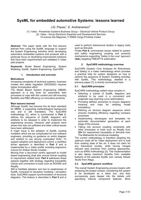
<strong>SysML</strong> <strong>for</strong> <strong>embedded</strong> <strong>automotive</strong> <strong>Systems</strong>: <strong>lessons</strong> <strong>learned</strong><br />
J-D. Piques 1 , E. Andrianarison 2<br />
(1): Valeo - Powertrain <strong>Systems</strong> Business Group – Electrical Vehicle Product Group<br />
(2): Valeo - Group Electronic Expertise and Development Services<br />
14 avenue des Béguines, F-95892 Cergy-Pontoise Cedex<br />
Abstract: This paper deals with the first <strong>lessons</strong><br />
<strong>learned</strong> from using the <strong>SysML</strong> language to support<br />
the System Engineering activities when developing<br />
<strong>automotive</strong> <strong>embedded</strong> systems and products with a<br />
particular focus on illustrating improvement solutions<br />
that have been experimented and validated in Valeo<br />
pilot projects.<br />
Keywords: Model Based Engineering, System<br />
Modeling, <strong>SysML</strong>, System Engineering, SysCARS<br />
1. Introduction and overview<br />
Motivations<br />
Increasing complexity of technical systems, business<br />
models and safety regulation (ISO26262) requires<br />
higher <strong>for</strong>malization ef<strong>for</strong>t.<br />
The Model Based System Engineering (MBSE)<br />
approach is a key lever <strong>for</strong> <strong>automotive</strong> lean<br />
processes to cope with this context and still ensuring<br />
flexibility and R&D efficiency on innovative products.<br />
Main <strong>lessons</strong> <strong>learned</strong><br />
Although <strong>SysML</strong> has become the de facto standard<br />
<strong>for</strong> MBSE, a supporting methodological background<br />
was and is still mandatory. The SysCARS<br />
methodology [1], which is summarized in Part 2,<br />
defines the sequence of <strong>SysML</strong> diagrams and<br />
artefacts to be released in order to implement the<br />
engineering process. However pilot projects have<br />
shown this was not sufficient and other critical issues<br />
have been addressed.<br />
A major issue is the adoption of <strong>SysML</strong> existing<br />
modelers which are too complicated <strong>for</strong> non software<br />
engineers, providing no guidance on which diagram<br />
and artefact to use among overloaded GUIs. To<br />
support adoption and deployment control, a workflow<br />
driven approach is described in Part 3 and is<br />
implemented by a Valeo profile including ergonomic<br />
macros <strong>for</strong> Artisan Studio modeler.<br />
Moving from a document centric approach to model<br />
based engineering shall also ensure <strong>for</strong>mal coupling<br />
to requirement related tools. Part 4 addresses these<br />
aspects together with strategy regarding traceability<br />
checks and connection to tools such as DOORS and<br />
Reqtify.<br />
Still to facilitate adoption and due to weaknesses of<br />
<strong>SysML</strong> compared to discipline modeling / simulation<br />
tools, SysCARS support synchronization of structural<br />
diagrams. This feature is described in Part 5 and is<br />
used to per<strong>for</strong>m behavioural studies in legacy tools<br />
such as Simulink.<br />
Finally Part 6, summarizes issues related to system<br />
and safety engineering coupling and presents<br />
mechanisms supporting “Safety In the Loop” approach<br />
(SaIL) targeting FMEA/FTA automation.<br />
2. SysCARS methodology overview<br />
SysCARS (System Core Analyses <strong>for</strong> Robustness<br />
and Safety) is a Valeo methodology which provides<br />
a practical help <strong>for</strong> system designers on how to<br />
per<strong>for</strong>m the sequence of System modeling activities<br />
with <strong>SysML</strong>. This methodology, detailed in a<br />
previous paper [1], is shortly summarized here.<br />
2.1. SysCARS principles<br />
SysCARS methodology added value consists in:<br />
• Selecting a subset of <strong>SysML</strong> diagrams and<br />
artefacts to be used in a convenient and<br />
pragmatic way (learning curve optimization)<br />
• Providing defined semantics to ensure diagrams<br />
meaning and rules <strong>for</strong> verifying model<br />
consistency<br />
• Defining an obvious diagram sequence which<br />
ensures modeling efficiency regarding company<br />
processes<br />
• Implementing stereotypes and templates <strong>for</strong><br />
automatic documentation generation at each<br />
stage of the process<br />
• Taking into account coupling constraints with<br />
other processes or tools such as Reqtify from<br />
IBM <strong>for</strong> requirement traceability or Simulink from<br />
The Mathworks <strong>for</strong> functional modeling<br />
The current methodology is there<strong>for</strong>e targeting the<br />
optimum trade off <strong>for</strong> Valeo deployment and is built<br />
from existing state of the art. It does not claim <strong>for</strong><br />
any theoretical novelty, while having merged<br />
relevant best practices from existing approaches,<br />
such as EIRIS methodology [2]. This implementation<br />
is also taking maximum benefits from available<br />
features of the selected <strong>SysML</strong> tool, namely Artisan<br />
Studio from Atego.<br />
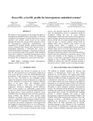
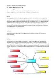
2.2. SysCARS generic workflow<br />
The overall System Engineering process begins with<br />
analyzing the project context, considering the system<br />
to be developed as a black box, and then<br />
successively goes deeper into the details until<br />
specifying internal component features. More<br />
Page 1/10
GROUPING<br />
ALLOCATION<br />
precisely the SysCARS methodology is divided into<br />
five major phases:<br />
• Stakeholder needs definition<br />
• Requirements analysis<br />
• Logical architecture design<br />
• Physical architecture design<br />
• Components needs definition<br />
For clarity purpose, the process and the sequence of<br />
activities are described in a pure sequential way.<br />
However, in practice, different steps could be<br />
per<strong>for</strong>med simultaneously with iterative and mutual<br />
refinements.<br />
Moreover, each phase systematically ends with:<br />
• Traceability analysis, to check the consistency<br />
and completeness of activities per<strong>for</strong>med and<br />
artefacts created,<br />
• Automatic generation of a document making a<br />
synthesis of the activities per<strong>for</strong>med (SND:<br />
Stakeholder Needs Document, SyRD: System<br />
Requirement Document, SyDD: System Design<br />
Document, CND: Component Needs Document).<br />
2.3. SysCARS optimized workflows<br />
The SysCARS workflow is described below.<br />
Stakeholders Needs<br />
Definition<br />
Requirements<br />
Analysis<br />
Logical Architecture<br />
Design<br />
Physical Architecture<br />
Design<br />
1a 1b 1c 1d<br />
Context<br />
External<br />
Interfaces<br />
Internal<br />
Functions<br />
Usage<br />
Main<br />
Services<br />
User<br />
Scenarios<br />
2a 2b 2c 2d<br />
3a<br />
4a<br />
Candidate<br />
Solutions<br />
3b<br />
Logical<br />
Architecture<br />
3c<br />
System<br />
Scenarios<br />
Log Internal<br />
Interfaces<br />
4b 4c 4d<br />
Modes<br />
BDD UCD SD STM<br />
IBD<br />
UCD<br />
AD BDD IBD<br />
BDD<br />
States<br />
STM<br />
Physical<br />
Phy Physical<br />
Internal<br />
Phy Physical<br />
Internal<br />
Physical<br />
Architecture<br />
Physical<br />
Interfaces<br />
Physical<br />
Physical<br />
Internal Scenarios<br />
Internal<br />
Architecture<br />
Internal<br />
Internal<br />
Architecture<br />
BDD Interfaces<br />
IBD Scenarios<br />
SD<br />
Interfaces<br />
Scenarios<br />
SD<br />
SND<br />
SyRD<br />
SyDD<br />
Figure 01: SysCARS System Engineering Process<br />
The last stage (Component Needs Definition) has<br />
not been represented, because it is mainly an<br />
extraction of component artefacts from the physical<br />
architecture.<br />
The kind of diagram used at each step is given by its<br />
<strong>SysML</strong> acronym attached to the related activity<br />
block: Block Definition Diagram (BDD), Internal<br />
Block Diagram (IBD), Use Case Diagram (UCD),<br />
Sequence Diagram (SD), STate Machine diagram<br />
(STM), Activity Diagram (AD)<br />
Lessons <strong>learned</strong> on pilot projects have shown that in<br />
most situations it makes sense to bypass the<br />
elaboration of the logical breakdown and to directly<br />
allocate internal functions onto the physical<br />
architecture blocks. Indeed, physical architectures<br />
are very often frozen because resulting from carry<br />
over products and there<strong>for</strong>e the investigation of<br />
several candidate solutions is not necessary.<br />
Consequently, two kinds of optimized workflow have<br />
been defined depending on the project typology:<br />
• SysCARS-XS (eXtended Stream): For innovative<br />
products, the whole set of activities of the [figure<br />
01] are per<strong>for</strong>med, and in particular the<br />
investigation of several physical architectures.<br />
• SysCARS-CS (Core Stream): For carry over<br />
products, the activities represented by grey boxes<br />
on the [figure 01] are not per<strong>for</strong>med.<br />
3. Workflow-driven approach<br />
3.1. A specific profile <strong>for</strong> customizing <strong>SysML</strong><br />
GUIs of <strong>SysML</strong> existing tools remain too complicated<br />
<strong>for</strong> a non software specialist, which is the targeted<br />
audience <strong>for</strong> System Engineering. Indeed, <strong>SysML</strong><br />
user interfaces provide confusing and unneeded<br />
features from the UML world. Very often, UML and<br />
<strong>SysML</strong> artefacts and diagrams are mixed without<br />
any possibility <strong>for</strong> the user to limit to a pure <strong>SysML</strong><br />
scope. Moreover, no guidance is provided on the<br />
relevant diagram to be used and on the correct<br />
ordering of operations.<br />
To cope with these drawbacks, a specific ergonomic<br />
profile (thereafter referred to as “Valeo Profile”) has<br />
been developed, introducing the concept of<br />
workflow-driven approach. The basic idea behind the<br />
workflow-driven approach is to provide the System<br />
engineer with a step by step help throughout the<br />
SysCARS engineering workflow. Moreover, at each<br />
step of the workflow, only relevant features and<br />
diagrams are available in a simplified GUI.<br />
The mechanisms of the workflow driven approach<br />
are detailed in the chapters below.<br />
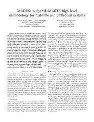
3.2. Workflow diagram navigation<br />
When creating a new model with the Valeo profile,<br />
this model directly opens a pre-defined “workflow<br />
diagram”. The “workflow diagram” is the central<br />
element of the Valeo Profile, defining the sequence<br />
of modeling activities to be per<strong>for</strong>med in accordance<br />
with the SysCARS methodology [1]. In fact, the<br />
workflow diagram is simply a statechart diagram,<br />
where states and super-states respectively<br />
correspond to elementary activities and main stages<br />
of the SysCARS methodology. No more than one<br />
elementary state can be active at one moment; i.e.<br />
only one kind of elementary activity should be<br />
per<strong>for</strong>med. On the workflow diagram represented<br />
below, the active state is highlighted in blue.<br />
Page 2/10
Pre-defined Package Structure<br />
Embedded SysCARS Workflow<br />
Figure 02: Valeo Profile GUI Overview<br />
It is possible to navigate the states of the workflow<br />
diagram and to select the workflow commands<br />
available: “Next Step”, “Previous Step”, “Go to<br />
step…”. Then the modeling step is changed<br />
accordingly.<br />
3.4. GUI features defined by workflow state<br />
The current active state of the workflow diagram is<br />
used to monitor the look and feel of the <strong>SysML</strong><br />
modeler tool, in order to provide the user only with<br />
the features required at this step of the system<br />
modeling process. Consequently, command menus<br />
available in the object browser and toolbar menus on<br />
diagrams are both customized differently in each<br />
state of the workflow diagram.<br />
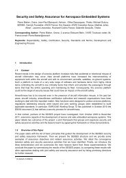
The diagram below clearly shows the level of<br />
simplification on command menus reached by the<br />
Valeo Profile.<br />
Customized contextual Toolbar<br />
Customized contextual Menu<br />
Workflow Menu<br />
Figure 03: Valeo Profile Navigation<br />
A second kind of navigation mechanism is available<br />
from the workflow diagram. Right-clicking on each<br />
state allows to reach the diagrams summarizing the<br />
results of this modeling step. The relevant diagrams<br />
should have been attached as associated diagrams<br />
once created.<br />
The implementation of the workflow in the profile is<br />
not frozen but configured using a dedicated XML file.<br />
This option enables further evolutions on the<br />
SysCARS workflow.<br />
3.3. Pre-defined package structure<br />
When creating a new model with the Valeo Profile,<br />
this model is also provided with a pre-defined<br />
package structure. This package hierarchy is directly<br />
correlated to states and super states of the workflow<br />
diagram, which in turn correspond to stages and<br />
steps of the SysCARS methodology.<br />
However, the user is free to organize differently<br />
artefacts and diagrams within a different package<br />
structure.<br />
As previously, the pre-defined package structure is<br />
not frozen but configured using a dedicated XML file.<br />
Figure 04: Customized Menus<br />
In the object browser window, the “create” command<br />
menu displayed when right-clicking an existing<br />
<strong>SysML</strong> object, is customized individually <strong>for</strong> each<br />
type of <strong>SysML</strong> artefact and diagram.<br />
In the graphical window, buttons available on each<br />
kind of diagram toolbars are also customized<br />
depending on the workflow diagram active state.<br />
The GUI features are evolutionary and configured<br />
from two dedicated XML files, one <strong>for</strong> the package<br />
browser command menus and one <strong>for</strong> the diagram<br />
toolbars.<br />
3.5. Stereotypes <strong>for</strong> documentation<br />
Documentation in a <strong>for</strong>mat that is easily<br />
comprehensible by a broad range of stakeholders<br />
remains an effective way to validate and<br />
communicate system design in<strong>for</strong>mation. The first<br />
thing to do is to precisely define the expected<br />
document <strong>for</strong>mat and contents by creating a<br />
corresponding template <strong>for</strong> the publishing tool. The<br />
same document template will be re-used on different<br />
projects, without any modification. Then, thanks to<br />
the publishing feature of the <strong>SysML</strong> tool, automatic<br />
document generation can be run on demand to<br />
collect and <strong>for</strong>mat data from the <strong>SysML</strong> model,<br />
without any special ef<strong>for</strong>t.<br />
Furthermore, separation between modeling data and<br />
document templates enables versatile customisation<br />
either to generate generic outputs or to address<br />
specific customer process.<br />
Page 3/10
The organisation of the documentation is also based<br />
on the workflow diagram breakdown. One particular<br />
kind of document (with related template) is defined<br />
<strong>for</strong> each workflow diagram super-state, in order to<br />
make the synthesis of modeling activities per<strong>for</strong>med<br />
within this stage:<br />
• SND (Stakeholder Needs Document) <strong>for</strong><br />
Stakeholder needs definition stage<br />
• SyRD (System Requirements Document) <strong>for</strong><br />
Requirements analysis stage<br />
• SyDD (System Design Document) <strong>for</strong> Logical and<br />
Physical architecture design<br />
• CND (Components Needs Design) <strong>for</strong><br />
Components needs definition stage<br />
<strong>SysML</strong> artefacts and diagrams created when being<br />
in a given super-state of the workflow diagram are<br />
automatically attached with stereotypes indicating<br />
that they should appear in the document associated<br />
with this super-state. The names of these<br />
stereotypes are built with the name of artefact or<br />
diagram prefixed by the name of the target<br />
document (e.g: SND_requirement). It is also possible<br />
to manually apply documentation stereotypes when<br />
artefacts should appear in multiple documents<br />
Stereotype <strong>for</strong> Documentation<br />
Figure 05: Documentation Stereotype Example<br />
The only thing left to do is to load in the publishing<br />
tool the pre-defined documentation template related<br />
to the workflow super-state to be documented, and<br />
then to launch documentation rendering. Diagrams<br />
and artefacts appearing in the final document are<br />
automatically filtered depending on their<br />
documentation stereotypes, i.e. on the stage of the<br />
workflow they have been created.<br />
4. Coupling to requirement management tools<br />
4.1. Efficient collaboration between tools<br />
Speaking about requirements in general may lead to<br />
adopt wrong requirement management tooling<br />
solutions. In fact, initial needs are iteratively refined<br />
during the engineering process, producing different<br />
levels of so-called requirements, corresponding to<br />
very different kind of in<strong>for</strong>mation. Typically these<br />
requirements can be classified in three categories:<br />
• User requirements describe the expected<br />
services from the end user point of view.<br />
• System requirements define the features of the<br />
system necessary to fulfil its mission.<br />
• Component requirements specify the internal<br />
constitutive parts necessary to implement the<br />
expected features.<br />
There<strong>for</strong>e, believing that a unique tool has the<br />
capability to address efficiently these three layers of<br />
in<strong>for</strong>mation is incorrect. On the contrary, a pragmatic<br />
approach adopted at Valeo is to take benefits from<br />
tools optimised <strong>for</strong> each field and to make them<br />
collaborate efficiently.<br />
Another common mistake is to mix up two categories<br />
of requirements related tools:<br />
• Requirement definition tools are containers of<br />
requirements (or any modeling artefacts used <strong>for</strong><br />
specification).<br />
• Requirement traceability tools do not define any<br />
requirements but have the ability to analyze<br />
requirements from requirement definition tools,<br />
and to analyze traceability links.<br />
A tool of the second category (e.g. Reqtify) can<br />
there<strong>for</strong>e be used as a gateway to optimise<br />
collaboration between tools of the first category<br />
(DOORS, <strong>SysML</strong> Artisan Studio, Simulink, …), <strong>for</strong><br />
synchronizing interface requirements and producing<br />
the whole traceability analysis. Another interesting<br />
property of this scheme is its ability to let people<br />
working with their discipline specific tools (such as<br />
Simulink <strong>for</strong> control design).<br />
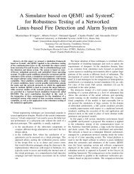
All the above mentioned principles are summarized<br />
on the figure below, showing the typical mapping of<br />
tools used at Valeo.<br />
USER<br />
Customer<br />
Repository<br />
User<br />
Requirements<br />
SYSTEM<br />
Product<br />
Component<br />
Requirements<br />
COMPONENT<br />
Discipline<br />
Architecture<br />
Tools<br />
Development<br />
Tools<br />
Customer<br />
Customer<br />
Needs<br />
Needs<br />
Architecture Breakdown<br />
Traceability<br />
Results<br />
Refined Requirements<br />
Design/Validation Elements<br />
REQTIFY<br />
Figure 06: Requirements Related Tools Mapping<br />
4.2. Distributed requirement storage<br />
Classical requirement management approaches<br />
assume that all requirements shall be written in<br />
natural language inside a centralized database<br />
(typically DOORS). Then, <strong>SysML</strong> modeling artefacts<br />
are only considered as intermediary by-products that<br />
need to be finally translated into textual<br />
requirements. This process makes sense in the<br />
aerospace or railway transportation fields were<br />
certification procedures are document-centric by<br />
Page 4/10
nature. However, in the <strong>automotive</strong> area, without any<br />
constraints from certification procedures, a pure<br />
model-centric approach is far more efficient.<br />
Consequently, maximum benefits are taken from<br />
expressive power and semi-<strong>for</strong>mal verification<br />
capability of the <strong>SysML</strong> modeling language.<br />
Requirements or requirements-like artefacts<br />
produced during system modeling activities are not<br />
re<strong>for</strong>mulated in natural language into an external<br />
centralized database. On the contrary, the model<br />
itself becomes the reference and the automatically<br />
generated documentation only an illustration of this<br />
reference. This philosophy is also used at<br />
implementation level, where requirements or more<br />
exactly requirements-like artefacts remains<br />
<strong>embedded</strong> into discipline specific native models<br />
(such as Simulink models, <strong>for</strong> control design).<br />
This approach optimises the requirement<br />
management ef<strong>for</strong>t because requirements are<br />
distributed among the tool locations where they have<br />
been defined, at each stage of the engineering<br />
process. As a counterpart, the consistency of the<br />
distributed requirements storage must be supported<br />
by powerful traceability tools, with efficient<br />
mechanisms <strong>for</strong> synchronizing interface<br />
requirements between modeling layers.<br />
4.3. User requirements in external repositories<br />
The initial stakeholder requirements (namely user<br />
requirements) remain captured in text specifications<br />
external to the <strong>SysML</strong> modeling tool, as in the<br />
classical approach. Typically, these specifications<br />
are stored in a DOORS database but may also be<br />
described using classical word processing or table<br />
editing softwares. The combination of the Reqtify<br />
gateway and of Artisan Studio modeling tool<br />
provides a mechanism to import external text<br />
requirements by creating mirroring <strong>SysML</strong><br />
requirements directly into the <strong>SysML</strong> model and to<br />
later maintain these data synchronized. In fact, three<br />
kinds of synchronization mechanisms are available:<br />
• Synchronization with a DOORS database<br />
• Synchronization with any kind of requirement file<br />
captured with Reqtify<br />
• Synchronization with Excel files (feature added<br />
by the Valeo Profile)<br />
The SysCARS modeling activities per<strong>for</strong>med to<br />
analyze stakeholder needs can result in proposing<br />
updates to the user requirements baseline. However,<br />
the textual requirements are <strong>for</strong>mally updated and<br />
controlled in the external requirement repository and<br />
changes are propagated to the <strong>SysML</strong> model thanks<br />
to the synchronization mechanism<br />
4.4. System and component requirements<br />
inside the <strong>SysML</strong> model<br />
Requirements produced during <strong>SysML</strong> modeling<br />
activities are not re<strong>for</strong>mulated in natural language<br />
into an external centralized repository. As a<br />
consequence, system and component level<br />
requirements are located inside the <strong>SysML</strong> model,<br />
taking benefits from internal traceability links with<br />
other model artefacts.<br />
The standard <strong>SysML</strong> requirement object being<br />
mainly limited to an identifier and a description field,<br />
it has been necessary to add complementary<br />
attributes, <strong>for</strong> efficient requirement management.<br />
The figure bellows shows these additional fields<br />
added by the Valeo profile, using tag definitions.<br />
Requirements Attributes<br />
Figure 07: Stereotyped Requirements Attributes<br />
Another approach under investigation, but not used<br />
on the first pilot projects, is to limit the use of <strong>SysML</strong><br />
requirements to non functional requirements. Then,<br />
functional requirements are represented by <strong>SysML</strong><br />
artefacts attached to constitutive blocks, typically by<br />
operations and states. More than avoiding<br />
re<strong>for</strong>mulating functions (described by operations) or<br />
states into functional requirements, this approach<br />
also saves the cost of declaring traceability<br />
relationships between structural elements and<br />
related functions. Indeed, operations and states are<br />
already tightly linked to their owning blocks.<br />
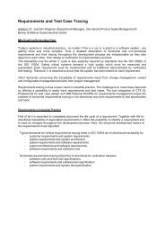
4.5. SysCARS traceability model<br />
The traceability model adopted in the SysCARS<br />
methodology has been pragmatically defined taking<br />
into account the features of the <strong>SysML</strong> modeling tool<br />
and the kind of verification that could be later<br />
per<strong>for</strong>med.<br />
The main rules used <strong>for</strong> defining traceability<br />
relationships are the following:<br />
• Derive is used between two levels of<br />
requirements<br />
• Refine is used between a use case or a scenario<br />
and the requirement elicitated<br />
• Satisfy is used between a model artefact (state,<br />
port, operation, block) and the requirement<br />
implemented<br />
• Trace is used between two representations of the<br />
same item, either refined between modeling<br />
levels or re<strong>for</strong>mulated at the same level<br />
Page 5/10
B1<br />
CONTEXT (BDD)<br />
INTERFACES (IBD)<br />
B2<br />
B1.1 B1.2 B2.1 B2.2<br />
Fa<br />
Fc<br />
Fe<br />
PBS (BDD)<br />
Fb<br />
Fd<br />
n<br />
n<br />
1<br />
USAGE (UCD)<br />
Intent1<br />
Intent2<br />
Service1<br />
Service2<br />
SERVICES (UCD)<br />
B1.1<br />
B2.1<br />
Fc<br />
Fd<br />
B1.2<br />
Fa<br />
INTERFACES (IBD)<br />
n<br />
n<br />
n<br />
SCENARIOS (SD)<br />
SCENARIOS (SD)<br />
SCENARIOS (SD)<br />
Mod3<br />
Mod1<br />
State3<br />
F<br />
1<br />
State1<br />
B2.1 B1.2 B2.2<br />
F<br />
c<br />
F<br />
d<br />
ALLOCATION<br />
F<br />
a<br />
F<br />
b<br />
n<br />
n<br />
DECOMPOSITION<br />
F1.1 F1.2 F1.2<br />
1.2.1 1.2.3 1.2.4<br />
Fa Fb Fe Fd<br />
DECOMPOSITIONS (AD)<br />
n<br />
n<br />
Mod1<br />
Mod3<br />
MODES (STM)<br />
State1<br />
State3<br />
STATES (STM)<br />
DECOMPOSITION<br />
ALLOCATION<br />
Mod2<br />
State2<br />
1<br />
1<br />
The figure below represents the corresponding<br />
SysCARS traceability scheme.<br />
Stakeholders Needs<br />
Definition<br />
Requirements<br />
Analysis<br />
Logical Architecture<br />
Design<br />
Physical Architecture<br />
Design<br />
system<br />
(context)<br />
system<br />
System<br />
(physical)<br />
SATISFIES<br />
System (physical)<br />
UserReqs<br />
1a 1b 1c 1d<br />
SysReqs<br />
CompReqs<br />
system<br />
(context)<br />
2a 2b 2c 2d<br />
4b 4c 4d<br />
SATISFIES<br />
REFINES<br />
REFINES<br />
SATISFIES<br />
DERIVES<br />
DERIVES<br />
SATISFIES<br />
SATISFIES<br />
system<br />
3a<br />
SATISFIES<br />
SATISFIES<br />
Figure 08: SysCARS Traceability Scheme<br />
Refine and Satisfy relationships shall connect<br />
artefacts developed at the same modeling stage,<br />
while Derive and Trace relationships are also<br />
capable of linking artefacts of neighbouring levels.<br />
4.6. Traceability analyses<br />
The requirement traceability verification activities are<br />
invoked throughout the whole system engineering<br />
process. In fact, two kinds of traceability analyses<br />
are per<strong>for</strong>med:<br />
• Internal traceability analysis between <strong>SysML</strong><br />
model artefacts, directly generated using the<br />
<strong>SysML</strong> tool,<br />
• External traceability analysis, between the<br />
distributed requirement repositories, done using a<br />
general purpose requirement traceability tool<br />
such as Reqtify.<br />
Internal traceability analyses are the ending activities<br />
per<strong>for</strong>med at each stage of the workflow to verify the<br />
model consistency (refer to green states of the<br />
workflow diagram, [figure 02]). They use requirement<br />
tables and traceability matrices to check the<br />
coverage of all requirements by appropriate model<br />
artefacts, in accordance with the traceability model<br />
presented at the previous paragraph. These<br />
matrixes and tables are generated on demand at<br />
Excel <strong>for</strong>mat.<br />
4.7. Towards modeling rules verification<br />
In future projects, it is plan to use a modeling rule<br />
checker to automatically verify the consistency and<br />
the completeness of the model, in accordance with<br />
the traceability scheme. The idea of these rules is to<br />
check that each kind of requirement is effectively<br />
covered, and covered by the appropriate modeling<br />
artefact.<br />
The verification rules will be based on several<br />
properties of the <strong>SysML</strong> objects and relationships:<br />
• Category of object,<br />
• Value of the stereotype indicating at which<br />
modeling stage the object has been produced,<br />
• Values of its specific qualification attributes,<br />
• Type of relationship used between objects.<br />
A typical rule should be written under the following<br />
<strong>for</strong>mat:<br />
• “Each requirement of this level and of this type<br />
shall be covered by this category of object, with<br />
this type of relationship, the linked objects being<br />
respectively produced at these modeling stages”.<br />
5. Coupling to control design tools<br />
The issue of coupling a <strong>SysML</strong> tool to discipline<br />
related tools (and particularly simulation tools) is not<br />
studied in general but limited to coupling to control<br />
design and software development environments, and<br />
particularly to Matlab/Simulink.<br />
5.1. Static verification rather than cosimulation<br />
Some approaches promote use of the <strong>SysML</strong> model<br />
as an integration framework <strong>for</strong> building a whole<br />
executable system model, in order to analyze the<br />
dynamics of the system. To support this, the static<br />
system modeling environment must be upgraded by<br />
execution mechanisms, with closed connection to<br />
discipline specific simulation tools.<br />
This way has not been chosen at Valeo’s <strong>for</strong> several<br />
reasons:<br />
• A higher degree of sophistication of the <strong>SysML</strong><br />
environment would go against a wide adoption by<br />
(generalist) system engineers.<br />
• Somehow, there is a contradiction between flat<br />
deep detailed modeling and the layered<br />
refinement approach promoted by system<br />
engineering.<br />
• Simulation and co-simulation capabilities of<br />
<strong>SysML</strong> tools are quite limited compared to<br />
domain specific tools.<br />
• For large scale system, a full integration<br />
simulated model is practically intractable.<br />
The final objective being the verification and<br />
validation of the whole system model, a static<br />
verification of traceability properties, as discussed in<br />
previous paragraphs, has been preferred. The<br />
purpose is then to gain maximal confidence in the<br />
completeness of the intellectual progress which led<br />
to the physical architecture solution.<br />
In a second time, as explained in the next<br />
paragraph, each component will be refined (and<br />
possibly simulated) independently in its discipline<br />
related development (and possibly modeling)<br />
environment, based on input data from the system<br />
model.<br />
5.2. Transfer of structure description to<br />
Simulink<br />
The problem of collaboration between <strong>SysML</strong> and<br />
Simulink is not stated in terms of (co)simulation but<br />
rather in terms of efficiently transferring and<br />
Page 6/10
synchronizing modeling data between both<br />
environments. The synchronization at architecture<br />
description level was proven to be an efficient way to<br />
transfer in<strong>for</strong>mation between system engineering<br />
teams and control design teams.<br />
In practice, the approach selected <strong>for</strong> pilot projects<br />
was to transfer the IBD structural descriptions of<br />
control law components, from <strong>SysML</strong> towards<br />
Simulink. The resulting Simulink models, initially<br />
corresponding to empty structures are further<br />
refined, and control algorithms implemented,<br />
simulated and validated inside the Simulink modeling<br />
and execution environment.<br />
The two figures below show an example of<br />
synchronization between a <strong>SysML</strong> Internal Block<br />
Diagram and Simulink dataflow model.<br />
ibd Detailed Design [VehicleEnergyManager]<br />
vem_CanFrame<br />
: CANBusController<br />
CanFrame<br />
IceTorqueRequest<br />
BatteryVoltage<br />
VehicleAcceleration<br />
AccelPedalPosition<br />
ElectricTorqueRequest<br />
BatteryVoltage<br />
VehicleAcceleration<br />
AccelPedalPosition<br />
«block»<br />
«Physical Block»<br />
VehicleEnergyManagementUnit-VEMU<br />
: BatterySOCEstimator<br />
: TractionControlMonitor<br />
: TorqueRequestEstimator<br />
BatterySOC<br />
TractionStatus<br />
TractionStatus<br />
TorqueRequest<br />
BatterySOC<br />
: IceElectricBalanceManager<br />
TorqueRequest<br />
IceTorqueRequest<br />
ElectricTorqueRequest<br />
Figure 09: <strong>SysML</strong> Controller Architecture (IBD)<br />
ElectricTorqueRequest<br />
IceTorqueRequest<br />
CANBusController<br />
bc<br />
BatteryVoltage<br />
VehicleAcceleration<br />
AccelPedalPosition<br />
BatteryVoltage<br />
VehicleAcceleration<br />
AccelPedalPosition<br />
BatterySOCEstimator<br />
bsocm<br />
TractionControlMonitor<br />
tcm<br />
TorqueRequestEstimator<br />
tre<br />
BatterySOC<br />
TractionStatus<br />
TorqueRequest<br />
IceElectricBalanceManager<br />
TractionStatus<br />
ElectricTorqueRequest<br />
BatterySOC<br />
TorqueRequest<br />
Figure 10: Simulink Controller Architecture<br />
(Dataflow)<br />
iebm<br />
IceTorqueRequest<br />
At the end of control design activities, Simulink<br />
simulation results are summarized by measures of<br />
efficiencies (MoEs) finally attached as “values” to the<br />
corresponding <strong>SysML</strong> block.<br />
Artisan Studio provides the main features required to<br />
synchronize and update efficiently <strong>SysML</strong> structural<br />
models and Simulink models: changes can be<br />
propagated in both directions. However, extensions<br />
in the existing mechanisms would be necessary <strong>for</strong> a<br />
full interoperability between both environments.<br />
These suggested evolutions are presented in the<br />
next paragraph.<br />
5.3. Mapping between <strong>SysML</strong> and Simulink<br />
structural artefacts<br />
The table below presents the detailed mapping <strong>for</strong><br />
an efficient synchronization of structural descriptions<br />
between <strong>SysML</strong> Internal Block Diagrams and<br />
Simulink Dataflow models. Currently existing<br />
features of Artisan Studio are written in standard<br />
font, while suggested extensions are written with<br />
bold characters.<br />
<strong>SysML</strong><br />
Internal Block Diagram<br />
Block<br />
Part<br />
Flow port (in)<br />
Flow port (out)<br />
Connector<br />
Name of the connected<br />
out flow port<br />
Item flow<br />
Block description<br />
Sequence diagram<br />
Simulink<br />
Dataflow model<br />
System MDL<br />
Model Reference<br />
Sub-system<br />
Inport<br />
Trigger port<br />
Outport<br />
Connecting line<br />
Connecting line name<br />
(Signal name)<br />
Documentation block<br />
Signal builder<br />
Figure 11: Mapping Between IBD and Simulink<br />
The main mandatory evolutions required are related<br />
to the ability to deal with Simulink events and not<br />
only with continuous flows. Indeed, events are<br />
systematically used to specify control flow<br />
mechanisms of algorithms. There<strong>for</strong>e, it should be at<br />
least possible to map <strong>SysML</strong> (in) Flow Ports onto<br />
Simulink trigger ports (with “function call” trigger type<br />
option).<br />
The ability to transfer names to Simulink flow lines is<br />
also mandatory, because in most situations they are<br />
used as variable names by automatic code<br />
generation tools.<br />
It would be potentially very interesting to transfer<br />
data related to the expected behaviour of the<br />
algorithm. <strong>SysML</strong> sequence diagrams describing test<br />
cases could be translated into Simulink signal builder<br />
blocks.<br />
The Simulink environment itself could also be<br />
improved with the capability to declare traceability<br />
links from Simulink sub-systems towards <strong>SysML</strong><br />
artefacts, and particularly requirements. These links<br />
could be declared directly between tools or via an<br />
intermediate XMI file.<br />
Page 7/10
UNUSED IN CORE STREAM (SysCARS-CS)<br />
B1<br />
ACTORS (BDD)<br />
INTERFACES (IBD)<br />
B2<br />
B1.1 B1.2 B2.1 B2.2<br />
Fa<br />
Fc<br />
Fe<br />
PBS (BDD)<br />
Fb<br />
Fd<br />
n<br />
n<br />
1<br />
USAGE (UCD)<br />
Intent1<br />
Intent2<br />
Service1<br />
Service2<br />
SERVICES (UCD)<br />
B1.1<br />
B2.1<br />
Fc<br />
Fd<br />
B1.2<br />
Fa<br />
INTERFACES (IBD)<br />
n<br />
n<br />
n<br />
ALLOCATION<br />
SCENARIOS (SD)<br />
SCENARIOS (SD)<br />
SCENARIOS (SD)<br />
Mod3<br />
Mod1<br />
State3<br />
F<br />
1<br />
State1<br />
F1.1 F1.2 F1.2<br />
1.2.1 1.2.3 1.2.4<br />
Fa Fb Fe Fd<br />
DECOMPOSITIONS (AD)<br />
B2.1 B1.2 B2.2<br />
F<br />
c<br />
F<br />
d<br />
F<br />
a<br />
F<br />
b<br />
n<br />
n<br />
n<br />
DECOMPOSITION<br />
ALLOCATION<br />
n<br />
Mod1<br />
Mod3<br />
MODES (STM)<br />
State1<br />
State3<br />
STATES (STM)<br />
Mod2<br />
State2<br />
1<br />
1<br />
6. Functional safety handling with SysCARS<br />
The new regulation ISO26262 focusing on<br />
Functional Safety, requires a higher level of<br />
<strong>for</strong>malization and traceability, and promotes the<br />
<strong>for</strong>malization of technical safety concepts in order to<br />
validate system architectures regarding safety<br />
expectations.<br />
This part focuses on the ongoing SysCARS<br />
evolutions to support Safety In the Loop (SaIL).<br />
6.1. General<br />
System engineering shall reconcile all the different<br />
aspects of the system to be designed. Among the<br />
multiple points of view, Functional safety is a key<br />
one. The final architecture shall integrate both<br />
system and functional safety expectations. There<strong>for</strong>e<br />
safety can not be addressed separately in a parallel<br />
and disconnected engineering domain.<br />
Despite following a regular system engineering<br />
process, Functional safety uses dedicated analyses<br />
to achieve safety demonstrations. In the rest of the<br />
chapter, focus is dedicated to major synchronization<br />
points, exchanged artefacts and impacts regarding<br />
SysCARS process and tools.<br />
6.2. System & safety process background<br />
Per<strong>for</strong>ming process steps in the field, it appears that<br />
system engineering has a natural tendency to focus<br />
more on functional and nominal operations, while<br />
Functional safety focuses on malfunctioning and<br />
degraded operations. SysCARS is supporting both,<br />
and provides guidance <strong>for</strong> technical safety concept<br />
<strong>for</strong>malization as required by ISO26262:<br />
At “Stakeholders Needs definition” level<br />
Key engineering artefacts:<br />
• specific scenarios related to critical safety<br />
contexts or degraded operations<br />
• specific safety modes, related per<strong>for</strong>mance<br />
and availability of functions<br />
SysCARS artefacts:<br />
• using regular diagrams but dedicated to<br />
safety focus and interactions<br />
Safety scenarios are a convenient way to capture in<br />
which conditions, malfunctions and safety goals are<br />
identified during Hazard analyses<br />
At “Requirement analysis” level”<br />
Key engineering artefacts:<br />
• safety requirements refining previous<br />
understandings to define safety expectations<br />
• specified external interfaces related to upper<br />
level safety mechanisms<br />
SysCARS artefacts:<br />
• using regular diagrams but dedicated to<br />
safety focus and interactions<br />
Safety goals/requirements generally use a somehow<br />
negative <strong>for</strong>m (e.g. <strong>for</strong> an Electronic Power Steering,<br />
avoidance of higher torque assist than requested).<br />
While system engineers are flowing down “positive”<br />
requirements (testable …), functional safety<br />
engineering consists in:<br />
• trans<strong>for</strong>ming such “negative” goals into<br />
technical safety requirements allocated to<br />
implementation technologies (HW, SW, …)<br />
• applying proven design patterns (e.g. safety<br />
mechanisms) during design of technical<br />
safety concept to achieve this trans<strong>for</strong>mation<br />
Safety goals and requirements are implemented with<br />
regular <strong>SysML</strong> requirements and additional attributes<br />
(ASIL, related context …)<br />
At “Logical architecture design” level”<br />
Key engineering artefacts:<br />
• breakdown of provided services into internal<br />
functions with flow down of ASIL<br />
In general, due to a high level of reuse in the<br />
<strong>automotive</strong> projects, the logical architecture, as<br />
previously mentioned, is not seen as a valuable step,<br />
except <strong>for</strong> innovation projects with intermediate<br />
capitalization needs regarding allocation on multiple<br />
physical candidate architectures.<br />
The same applies to safety, where the major<br />
objective is to ensure the link between high level<br />
requirements and final implementation. Furthermore<br />
the ASIL decomposition, having to demonstrate non<br />
interference, makes only sense taking into<br />
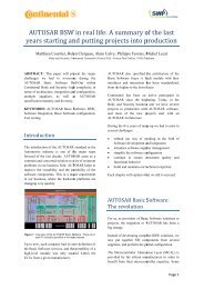
consideration hardware characteristics.<br />
Define Stakeholders<br />
Needs<br />
Analyze<br />
Requirements<br />
Functional<br />
Architectural Design<br />
Architecture<br />
Physical<br />
transferred to<br />
Architectural Design<br />
BMT (Simulink)<br />
1a 1b 1c 1d<br />
system<br />
(context)<br />
Services <strong>for</strong><br />
Hazard<br />
Analysis (PHA)<br />
2a 2b 2c 6b<br />
system<br />
System<br />
(physical)<br />
System (physical)<br />
3a<br />
4b 4c 4d<br />
system<br />
(context)<br />
system<br />
Architecture<br />
validated by<br />
FMEA<br />
Figure 12: SysCARS-CS coupling to safety activities<br />
At “Physical architecture design” level”<br />
Key engineering artefacts:<br />
• ASIL decomposition once internal functions<br />
are allocated to physical parts<br />
• “ASIL” of internal parts and interfaces (due<br />
to highest ASIL function allocated)<br />
Page 8/10
• introduction of additional parts related to<br />
required safety mechanisms<br />
• technical safety requirements impacting<br />
specific discipline<br />
SysCARS artefacts:<br />
• customization of IBDs with specific visual<br />
stereotypes to highlight safety related parts<br />
In SysCARS-CS, iterations are achieved between<br />
functional decomposition and physical architecture to<br />
work out the relevant decomposition depth and<br />
ensure the mapping. The same process is used to<br />
iterate and introduce additional safety mechanisms.<br />
Interactions and shared artefacts<br />
System and safety points of view are completing<br />
each other, enriching the same artefacts which shall<br />
be kept consistent in a common referential.<br />
Considering process iterations, an initial set of<br />
scenarios, internal functions, physical parts … is<br />
released by system engineers, and then modified or<br />
completed by safety engineers to meet safety<br />
expectations. Setting up SysCARS as a common<br />
backbone to couple system and safety engineering<br />
solves these issues.<br />
6.3. Safety specific verifications<br />
Whereas system and safety generate common<br />
design artefacts, discrepancy occurs when taking<br />
into account safety related verifications.<br />
Failure Modes and Effects Analyses (FMEA)<br />
To check the safety relevance of a given architecture<br />
(functions allocated on physical), a common analysis<br />
is the FMEA. Each part is considered as possibly<br />
being faulty, and occurrence of undesirable events at<br />
system scope are assessed.<br />
To achieve such analyses, the system descriptions<br />
shall be extended to dysfunctional modeling at part<br />
level:<br />
• part, input and output fault modes<br />
• part behaviour regarding faulty inputs, fault<br />
propagation to outputs<br />
• intrinsic part fault propagation to outputs<br />
These descriptions (together with part relations)<br />
allow mathematical checking of system properties<br />
such as occurrence of a undesirable event.<br />
Furthermore, working out dysfunctional behaviour<br />
per each part of the architecture allows:<br />
• to enable computer aided verification of the<br />
architecture using FMEA principles<br />
• to capitalize dysfunctional behaviour per part<br />
and there<strong>for</strong>e ease reuse of architecture<br />
subsets within new systems<br />
• an easier peer reviewing of dysfunctional<br />
descriptions (per part), whereas review of<br />
traditional FMEA is difficult<br />
Fault tree analyses (FTA)<br />
While FMEA is a deductive approach, allowing to<br />
verify compliance of a given architecture regarding<br />
all undesirable events (bottom up), FTA is a top<br />
down approach (inductive) done per undesirable<br />
event working out relevant contributing faults.<br />
Automated FMEA verification may output a FTA<br />
linking undesirable event to the relevant faults within<br />
the architecture (issues under work). This feature<br />
appears to be a major lever <strong>for</strong> efficient deployment<br />
of the ISO26262, while traditionally FTA and FMEA<br />
are concurrently done. Furthermore, the merged<br />
FTA is a key enabler to move <strong>for</strong>ward quantitative<br />
analyses.<br />
To draw FTA trees, either generated from<br />
architecture verification or done by hand from top to<br />
down, specific profiles have to be set up in the<br />
<strong>SysML</strong> editor.<br />
System decomposition<br />
Hazard<br />
analysis<br />
FMEA<br />
FMEA<br />
Feared<br />
event<br />
Generated<br />
FTA<br />
Generated<br />
FTA<br />
Generated<br />
FTA<br />
Generated<br />
FTA<br />
FE<br />
Merged FTA<br />
Figure 13: FTA Generation from SysCARS<br />
6.4. Process and tooling considerations<br />
From a process point of view, the key shared<br />
artefact is the physical architecture (key interface<br />
between system levels as well), including allocated<br />
technical functions, and completed with<br />
dysfunctional in<strong>for</strong>mation.<br />
Dysfunctional descriptions in system process<br />
Such approach already exists in some industrial<br />
domains and tools are available in order to achieve<br />
such safety architecture verification (e.g. using the<br />
Altarica language and model checker).<br />
These studies are in general per<strong>for</strong>med by safety<br />
modeling experts. The involvement of system<br />
designer is reduced to providing in<strong>for</strong>mation during<br />
interviews. This process and required safety<br />
modeling skills are a major show stopper <strong>for</strong><br />
<strong>automotive</strong> deployment.<br />
The SysCARS objective is to tightly couple<br />
engineering domains. System designers are the<br />
ones who best know both functional and<br />
dysfunctional behaviour. There<strong>for</strong>e, dysfunctional<br />
modeling shall be integrated in their processes (at<br />
least <strong>for</strong> initial versions, later completed by safety<br />
experts).<br />
Page 9/10
Thus, a pragmatic dysfunctional <strong>for</strong>malization is<br />
under study, which will be a subset of Altarica<br />
available concepts, also taking benefits from York<br />
FTPC research and using as much as possible easy<br />
notations such as Boolean algebra.<br />
Trans<strong>for</strong>mation to Altarica tools (or others) with<br />
generation of the required code (taking into<br />
consideration safety design patterns or functions<br />
typologies) is targeted.<br />
6.5. SysCARS-SaIL status<br />
While <strong>lessons</strong> <strong>learned</strong> have confirmed SysCARS<br />
capability to <strong>for</strong>malize ISO26262 technical safety<br />
concepts, extension is required to seamlessly<br />
implement “SaIL” concept (Safety In the Loop).<br />
Introduction of dysfunctional modeling and coupling<br />
to safety tools, will allow efficient safety architecture<br />
verification. Valeo internal ef<strong>for</strong>t is completed by<br />
collaboratively addressing these topics in the<br />
framework of European projects such as SAFE<br />
(ITEA2, Safe Automotive soFtware architEcture).<br />
7. Conclusion<br />
Learning on Valeo pilot projects have confirmed that<br />
the <strong>SysML</strong> language offers an adequate lever to<br />
extend the modeling practices to the area of System<br />
Engineering including functional safety analyses.<br />
Valeo experiences have shown that a successful<br />
approach requires a precisely defined modeling<br />
methodology (SysCARS).<br />
Furthermore, the customisation of existing tools in a<br />
workflow driven mindset is mandatory. However,<br />
further improvements remain necessary on<br />
commercial tools regarding ergonomics and<br />
interfacing with simulation and safety analyses tools.<br />
8. Acronyms<br />
AD Activity Diagram<br />
ASIL Automotive Safety Integrated Level<br />
BDD Block Definition Diagram<br />
CND Component Needs Document<br />
FMEA Failure Mode Effects Analysis<br />
FTA Fault Tree Analysis<br />
FTPC Fault Trans<strong>for</strong>mation and Propagation<br />
Calculation<br />
GUI Graphical User Interface<br />
HW HardWare<br />
IBD Internal Block Diagram<br />
ISO26262 Automotive Functional Safety Regulation<br />
ITEA In<strong>for</strong>mation Technology <strong>for</strong> European<br />
Advance<br />
MBSE Model Based System Engineering<br />
MDL Simulink file extension<br />
MoE Measure Of Effectivness<br />
REQ REQuirement Diagram<br />
SAFE Safe Automotive soFtware architEcture<br />
SD Sequence Diagram<br />
SND Stakeholders’ Needs Document<br />
STM STate Machine diagram<br />
SaIL Safety In the Loop<br />
SyDD System Design Document<br />
SyRD System Requirements Document<br />
UCD Use case Diagram<br />
9. References<br />
[1] Eric Andrianarison, Jean-Denis Piques: "<strong>SysML</strong> <strong>for</strong><br />
<strong>embedded</strong> <strong>automotive</strong> <strong>Systems</strong>: a practical<br />
approach", ERTS 2010.<br />
[2] Françoise Caron: "Exigences et ingénierie<br />
système : Mise en œuvre avec <strong>SysML</strong>", EIRIS<br />
Conseil, 2008.<br />
[3] A. Arnold, G. Point, A. Griffault, A. Rauzy “The<br />
Altarica <strong>for</strong>malism <strong>for</strong> describing concurrent<br />
systems”, 2000<br />
[4] Richard F. Paige, Louis M. Rose, Xiaocheng Ge,<br />
Dimitrios S. Kolovos, and Phillip J. Brooke: “FPTC:<br />
Automated Safety Analysis <strong>for</strong> Domain-Specific<br />
Languages”, 2008<br />
Further bibliographical references can be found in [1]<br />
Page 10/10