SysML for embedded automotive Systems: lessons learned
SysML for embedded automotive Systems: lessons learned
SysML for embedded automotive Systems: lessons learned

You also want an ePaper? Increase the reach of your titles
YUMPU automatically turns print PDFs into web optimized ePapers that Google loves.
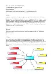
GROUPING<br />
ALLOCATION<br />
precisely the SysCARS methodology is divided into<br />
five major phases:<br />
• Stakeholder needs definition<br />
• Requirements analysis<br />
• Logical architecture design<br />
• Physical architecture design<br />
• Components needs definition<br />
For clarity purpose, the process and the sequence of<br />
activities are described in a pure sequential way.<br />
However, in practice, different steps could be<br />
per<strong>for</strong>med simultaneously with iterative and mutual<br />
refinements.<br />
Moreover, each phase systematically ends with:<br />
• Traceability analysis, to check the consistency<br />
and completeness of activities per<strong>for</strong>med and<br />
artefacts created,<br />
• Automatic generation of a document making a<br />
synthesis of the activities per<strong>for</strong>med (SND:<br />
Stakeholder Needs Document, SyRD: System<br />
Requirement Document, SyDD: System Design<br />
Document, CND: Component Needs Document).<br />
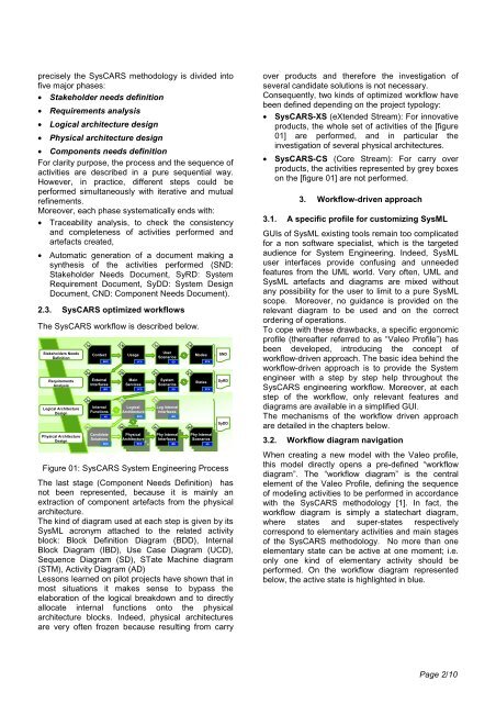
2.3. SysCARS optimized workflows<br />
The SysCARS workflow is described below.<br />
Stakeholders Needs<br />
Definition<br />
Requirements<br />
Analysis<br />
Logical Architecture<br />
Design<br />
Physical Architecture<br />
Design<br />
1a 1b 1c 1d<br />
Context<br />
External<br />
Interfaces<br />
Internal<br />
Functions<br />
Usage<br />
Main<br />
Services<br />
User<br />
Scenarios<br />
2a 2b 2c 2d<br />
3a<br />
4a<br />
Candidate<br />
Solutions<br />
3b<br />
Logical<br />
Architecture<br />
3c<br />
System<br />
Scenarios<br />
Log Internal<br />
Interfaces<br />
4b 4c 4d<br />
Modes<br />
BDD UCD SD STM<br />
IBD<br />
UCD<br />
AD BDD IBD<br />
BDD<br />
States<br />
STM<br />
Physical<br />
Phy Physical<br />
Internal<br />
Phy Physical<br />
Internal<br />
Physical<br />
Architecture<br />
Physical<br />
Interfaces<br />
Physical<br />
Physical<br />
Internal Scenarios<br />
Internal<br />
Architecture<br />
Internal<br />
Internal<br />
Architecture<br />
BDD Interfaces<br />
IBD Scenarios<br />
SD<br />
Interfaces<br />
Scenarios<br />
SD<br />
SND<br />
SyRD<br />
SyDD<br />
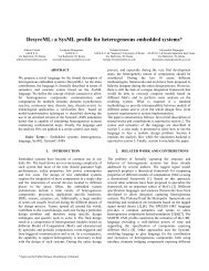
Figure 01: SysCARS System Engineering Process<br />
The last stage (Component Needs Definition) has<br />
not been represented, because it is mainly an<br />
extraction of component artefacts from the physical<br />
architecture.<br />
The kind of diagram used at each step is given by its<br />
<strong>SysML</strong> acronym attached to the related activity<br />
block: Block Definition Diagram (BDD), Internal<br />
Block Diagram (IBD), Use Case Diagram (UCD),<br />
Sequence Diagram (SD), STate Machine diagram<br />
(STM), Activity Diagram (AD)<br />
Lessons <strong>learned</strong> on pilot projects have shown that in<br />
most situations it makes sense to bypass the<br />
elaboration of the logical breakdown and to directly<br />
allocate internal functions onto the physical<br />
architecture blocks. Indeed, physical architectures<br />
are very often frozen because resulting from carry<br />
over products and there<strong>for</strong>e the investigation of<br />
several candidate solutions is not necessary.<br />
Consequently, two kinds of optimized workflow have<br />
been defined depending on the project typology:<br />
• SysCARS-XS (eXtended Stream): For innovative<br />
products, the whole set of activities of the [figure<br />
01] are per<strong>for</strong>med, and in particular the<br />
investigation of several physical architectures.<br />
• SysCARS-CS (Core Stream): For carry over<br />
products, the activities represented by grey boxes<br />
on the [figure 01] are not per<strong>for</strong>med.<br />
3. Workflow-driven approach<br />
3.1. A specific profile <strong>for</strong> customizing <strong>SysML</strong><br />
GUIs of <strong>SysML</strong> existing tools remain too complicated<br />
<strong>for</strong> a non software specialist, which is the targeted<br />
audience <strong>for</strong> System Engineering. Indeed, <strong>SysML</strong><br />
user interfaces provide confusing and unneeded<br />
features from the UML world. Very often, UML and<br />
<strong>SysML</strong> artefacts and diagrams are mixed without<br />
any possibility <strong>for</strong> the user to limit to a pure <strong>SysML</strong><br />
scope. Moreover, no guidance is provided on the<br />
relevant diagram to be used and on the correct<br />
ordering of operations.<br />
To cope with these drawbacks, a specific ergonomic<br />
profile (thereafter referred to as “Valeo Profile”) has<br />
been developed, introducing the concept of<br />
workflow-driven approach. The basic idea behind the<br />
workflow-driven approach is to provide the System<br />
engineer with a step by step help throughout the<br />
SysCARS engineering workflow. Moreover, at each<br />
step of the workflow, only relevant features and<br />
diagrams are available in a simplified GUI.<br />
The mechanisms of the workflow driven approach<br />
are detailed in the chapters below.<br />
3.2. Workflow diagram navigation<br />
When creating a new model with the Valeo profile,<br />
this model directly opens a pre-defined “workflow<br />
diagram”. The “workflow diagram” is the central<br />
element of the Valeo Profile, defining the sequence<br />
of modeling activities to be per<strong>for</strong>med in accordance<br />
with the SysCARS methodology [1]. In fact, the<br />
workflow diagram is simply a statechart diagram,<br />
where states and super-states respectively<br />
correspond to elementary activities and main stages<br />
of the SysCARS methodology. No more than one<br />
elementary state can be active at one moment; i.e.<br />
only one kind of elementary activity should be<br />
per<strong>for</strong>med. On the workflow diagram represented<br />
below, the active state is highlighted in blue.<br />
Page 2/10