SysML for embedded automotive Systems: lessons learned
SysML for embedded automotive Systems: lessons learned
SysML for embedded automotive Systems: lessons learned

Create successful ePaper yourself
Turn your PDF publications into a flip-book with our unique Google optimized e-Paper software.
B1<br />
CONTEXT (BDD)<br />
INTERFACES (IBD)<br />
B2<br />
B1.1 B1.2 B2.1 B2.2<br />
Fa<br />
Fc<br />
Fe<br />
PBS (BDD)<br />
Fb<br />
Fd<br />
n<br />
n<br />
1<br />
USAGE (UCD)<br />
Intent1<br />
Intent2<br />
Service1<br />
Service2<br />
SERVICES (UCD)<br />
B1.1<br />
B2.1<br />
Fc<br />
Fd<br />
B1.2<br />
Fa<br />
INTERFACES (IBD)<br />
n<br />
n<br />
n<br />
SCENARIOS (SD)<br />
SCENARIOS (SD)<br />
SCENARIOS (SD)<br />
Mod3<br />
Mod1<br />
State3<br />
F<br />
1<br />
State1<br />
B2.1 B1.2 B2.2<br />
F<br />
c<br />
F<br />
d<br />
ALLOCATION<br />
F<br />
a<br />
F<br />
b<br />
n<br />
n<br />
DECOMPOSITION<br />
F1.1 F1.2 F1.2<br />
1.2.1 1.2.3 1.2.4<br />
Fa Fb Fe Fd<br />
DECOMPOSITIONS (AD)<br />
n<br />
n<br />
Mod1<br />
Mod3<br />
MODES (STM)<br />
State1<br />
State3<br />
STATES (STM)<br />
DECOMPOSITION<br />
ALLOCATION<br />
Mod2<br />
State2<br />
1<br />
1<br />
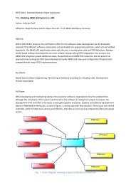
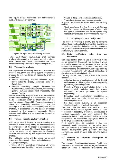
The figure below represents the corresponding<br />
SysCARS traceability scheme.<br />
Stakeholders Needs<br />
Definition<br />
Requirements<br />
Analysis<br />
Logical Architecture<br />
Design<br />
Physical Architecture<br />
Design<br />
system<br />
(context)<br />
system<br />
System<br />
(physical)<br />
SATISFIES<br />
System (physical)<br />
UserReqs<br />
1a 1b 1c 1d<br />
SysReqs<br />
CompReqs<br />
system<br />
(context)<br />
2a 2b 2c 2d<br />
4b 4c 4d<br />
SATISFIES<br />
REFINES<br />
REFINES<br />
SATISFIES<br />
DERIVES<br />
DERIVES<br />
SATISFIES<br />
SATISFIES<br />
system<br />
3a<br />
SATISFIES<br />
SATISFIES<br />
Figure 08: SysCARS Traceability Scheme<br />
Refine and Satisfy relationships shall connect<br />
artefacts developed at the same modeling stage,<br />
while Derive and Trace relationships are also<br />
capable of linking artefacts of neighbouring levels.<br />
4.6. Traceability analyses<br />
The requirement traceability verification activities are<br />
invoked throughout the whole system engineering<br />
process. In fact, two kinds of traceability analyses<br />
are per<strong>for</strong>med:<br />
• Internal traceability analysis between <strong>SysML</strong><br />
model artefacts, directly generated using the<br />
<strong>SysML</strong> tool,<br />
• External traceability analysis, between the<br />
distributed requirement repositories, done using a<br />
general purpose requirement traceability tool<br />
such as Reqtify.<br />
Internal traceability analyses are the ending activities<br />
per<strong>for</strong>med at each stage of the workflow to verify the<br />
model consistency (refer to green states of the<br />
workflow diagram, [figure 02]). They use requirement<br />
tables and traceability matrices to check the<br />
coverage of all requirements by appropriate model<br />
artefacts, in accordance with the traceability model<br />
presented at the previous paragraph. These<br />
matrixes and tables are generated on demand at<br />
Excel <strong>for</strong>mat.<br />
4.7. Towards modeling rules verification<br />
In future projects, it is plan to use a modeling rule<br />
checker to automatically verify the consistency and<br />
the completeness of the model, in accordance with<br />
the traceability scheme. The idea of these rules is to<br />
check that each kind of requirement is effectively<br />
covered, and covered by the appropriate modeling<br />
artefact.<br />
The verification rules will be based on several<br />
properties of the <strong>SysML</strong> objects and relationships:<br />
• Category of object,<br />
• Value of the stereotype indicating at which<br />
modeling stage the object has been produced,<br />
• Values of its specific qualification attributes,<br />
• Type of relationship used between objects.<br />
A typical rule should be written under the following<br />
<strong>for</strong>mat:<br />
• “Each requirement of this level and of this type<br />
shall be covered by this category of object, with<br />
this type of relationship, the linked objects being<br />
respectively produced at these modeling stages”.<br />
5. Coupling to control design tools<br />
The issue of coupling a <strong>SysML</strong> tool to discipline<br />
related tools (and particularly simulation tools) is not<br />
studied in general but limited to coupling to control<br />
design and software development environments, and<br />
particularly to Matlab/Simulink.<br />
5.1. Static verification rather than cosimulation<br />
Some approaches promote use of the <strong>SysML</strong> model<br />
as an integration framework <strong>for</strong> building a whole<br />
executable system model, in order to analyze the<br />
dynamics of the system. To support this, the static<br />
system modeling environment must be upgraded by<br />
execution mechanisms, with closed connection to<br />
discipline specific simulation tools.<br />
This way has not been chosen at Valeo’s <strong>for</strong> several<br />
reasons:<br />
• A higher degree of sophistication of the <strong>SysML</strong><br />
environment would go against a wide adoption by<br />
(generalist) system engineers.<br />
• Somehow, there is a contradiction between flat<br />
deep detailed modeling and the layered<br />
refinement approach promoted by system<br />
engineering.<br />
• Simulation and co-simulation capabilities of<br />
<strong>SysML</strong> tools are quite limited compared to<br />
domain specific tools.<br />
• For large scale system, a full integration<br />
simulated model is practically intractable.<br />
The final objective being the verification and<br />
validation of the whole system model, a static<br />
verification of traceability properties, as discussed in<br />
previous paragraphs, has been preferred. The<br />
purpose is then to gain maximal confidence in the<br />
completeness of the intellectual progress which led<br />
to the physical architecture solution.<br />
In a second time, as explained in the next<br />
paragraph, each component will be refined (and<br />
possibly simulated) independently in its discipline<br />
related development (and possibly modeling)<br />
environment, based on input data from the system<br />
model.<br />
5.2. Transfer of structure description to<br />
Simulink<br />
The problem of collaboration between <strong>SysML</strong> and<br />
Simulink is not stated in terms of (co)simulation but<br />
rather in terms of efficiently transferring and<br />
Page 6/10