SysML for embedded automotive Systems: lessons learned
SysML for embedded automotive Systems: lessons learned
SysML for embedded automotive Systems: lessons learned

Create successful ePaper yourself
Turn your PDF publications into a flip-book with our unique Google optimized e-Paper software.
The organisation of the documentation is also based<br />
on the workflow diagram breakdown. One particular<br />
kind of document (with related template) is defined<br />
<strong>for</strong> each workflow diagram super-state, in order to<br />
make the synthesis of modeling activities per<strong>for</strong>med<br />
within this stage:<br />
• SND (Stakeholder Needs Document) <strong>for</strong><br />
Stakeholder needs definition stage<br />
• SyRD (System Requirements Document) <strong>for</strong><br />
Requirements analysis stage<br />
• SyDD (System Design Document) <strong>for</strong> Logical and<br />
Physical architecture design<br />
• CND (Components Needs Design) <strong>for</strong><br />
Components needs definition stage<br />
<strong>SysML</strong> artefacts and diagrams created when being<br />
in a given super-state of the workflow diagram are<br />
automatically attached with stereotypes indicating<br />
that they should appear in the document associated<br />
with this super-state. The names of these<br />
stereotypes are built with the name of artefact or<br />
diagram prefixed by the name of the target<br />
document (e.g: SND_requirement). It is also possible<br />
to manually apply documentation stereotypes when<br />
artefacts should appear in multiple documents<br />
Stereotype <strong>for</strong> Documentation<br />
Figure 05: Documentation Stereotype Example<br />
The only thing left to do is to load in the publishing<br />
tool the pre-defined documentation template related<br />
to the workflow super-state to be documented, and<br />
then to launch documentation rendering. Diagrams<br />
and artefacts appearing in the final document are<br />
automatically filtered depending on their<br />
documentation stereotypes, i.e. on the stage of the<br />
workflow they have been created.<br />
4. Coupling to requirement management tools<br />
4.1. Efficient collaboration between tools<br />
Speaking about requirements in general may lead to<br />
adopt wrong requirement management tooling<br />
solutions. In fact, initial needs are iteratively refined<br />
during the engineering process, producing different<br />
levels of so-called requirements, corresponding to<br />
very different kind of in<strong>for</strong>mation. Typically these<br />
requirements can be classified in three categories:<br />
• User requirements describe the expected<br />
services from the end user point of view.<br />
• System requirements define the features of the<br />
system necessary to fulfil its mission.<br />
• Component requirements specify the internal<br />
constitutive parts necessary to implement the<br />
expected features.<br />
There<strong>for</strong>e, believing that a unique tool has the<br />
capability to address efficiently these three layers of<br />
in<strong>for</strong>mation is incorrect. On the contrary, a pragmatic<br />
approach adopted at Valeo is to take benefits from<br />
tools optimised <strong>for</strong> each field and to make them<br />
collaborate efficiently.<br />
Another common mistake is to mix up two categories<br />
of requirements related tools:<br />
• Requirement definition tools are containers of<br />
requirements (or any modeling artefacts used <strong>for</strong><br />
specification).<br />
• Requirement traceability tools do not define any<br />
requirements but have the ability to analyze<br />
requirements from requirement definition tools,<br />
and to analyze traceability links.<br />
A tool of the second category (e.g. Reqtify) can<br />
there<strong>for</strong>e be used as a gateway to optimise<br />
collaboration between tools of the first category<br />
(DOORS, <strong>SysML</strong> Artisan Studio, Simulink, …), <strong>for</strong><br />
synchronizing interface requirements and producing<br />
the whole traceability analysis. Another interesting<br />
property of this scheme is its ability to let people<br />
working with their discipline specific tools (such as<br />
Simulink <strong>for</strong> control design).<br />
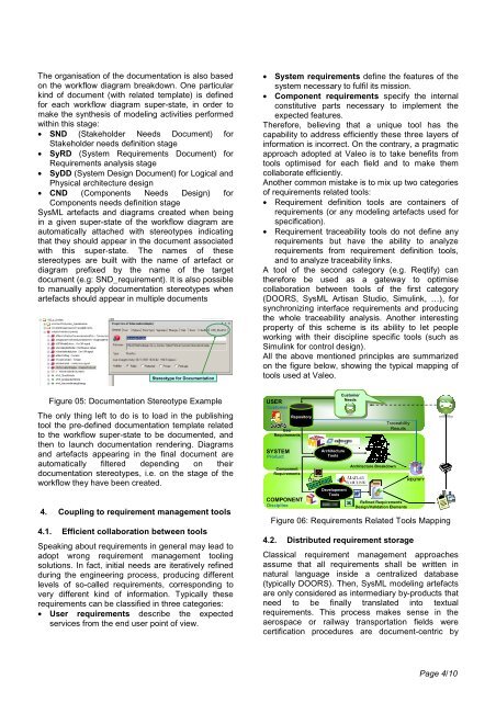
All the above mentioned principles are summarized<br />
on the figure below, showing the typical mapping of<br />
tools used at Valeo.<br />
USER<br />
Customer<br />
Repository<br />
User<br />
Requirements<br />
SYSTEM<br />
Product<br />
Component<br />
Requirements<br />
COMPONENT<br />
Discipline<br />
Architecture<br />
Tools<br />
Development<br />
Tools<br />
Customer<br />
Customer<br />
Needs<br />
Needs<br />
Architecture Breakdown<br />
Traceability<br />
Results<br />
Refined Requirements<br />
Design/Validation Elements<br />
REQTIFY<br />
Figure 06: Requirements Related Tools Mapping<br />
4.2. Distributed requirement storage<br />
Classical requirement management approaches<br />
assume that all requirements shall be written in<br />
natural language inside a centralized database<br />
(typically DOORS). Then, <strong>SysML</strong> modeling artefacts<br />
are only considered as intermediary by-products that<br />
need to be finally translated into textual<br />
requirements. This process makes sense in the<br />
aerospace or railway transportation fields were<br />
certification procedures are document-centric by<br />
Page 4/10