A SysML/MARTE high level methodology for real-time - Embedded ...
A SysML/MARTE high level methodology for real-time - Embedded ...
A SysML/MARTE high level methodology for real-time - Embedded ...

You also want an ePaper? Increase the reach of your titles
YUMPU automatically turns print PDFs into web optimized ePapers that Google loves.
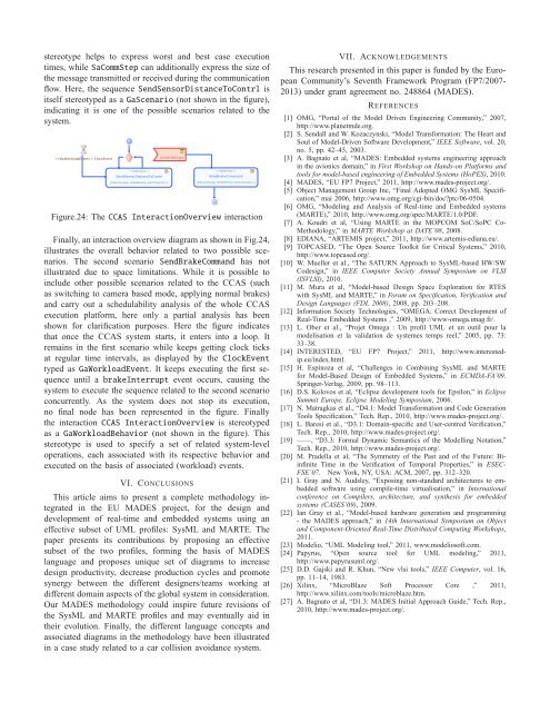
stereotype helps to express worst and best case execution<strong>time</strong>s, whileSaCommStep can additionally express the size ofthe message transmitted or received during the communicationflow. Here, the sequenceSendSensorDistanceToContrl isitself stereotyped as aGaScenario (not shown in the figure),indicating it is one of the possible scenarios related to thesystem. ClockEventSendSensorDistanceToContrl{ResourceUsage_ModelElement_execTime(43ms )}breakInterrputSendBrakeCommand{ResourceUsage_ModelElement_execTime(26ms )}Figure.24: TheCCAS InteractionOverview interactionFinally, an interaction overview diagram as shown in Fig.24,illustrates the overall behavior related to two possible scenarios.The second scenario SendBrakeCommand has notillustrated due to space limitations. While it is possible toinclude other possible scenarios related to the CCAS (suchas switching to camera based mode, applying normal brakes)and carry out a schedulability analysis of the whole CCASexecution plat<strong>for</strong>m, here only a partial analysis has beenshown <strong>for</strong> clarification purposes. Here the figure indicatesthat once the CCAS system starts, it enters into a loop. Itremains in the first scenario while keeps getting clock ticksat regular <strong>time</strong> intervals, as displayed by the ClockEventtyped asGaWorkloadEvent. It keeps executing the first sequenceuntil abrakeInterrupt event occurs, causing thesystem to execute the sequence related to the second scenarioconcurrently. As the system does not stop its execution,no final node has been represented in the figure. Finallythe interactionCCAS InteractionOverview is stereotypedas aGaWorkloadBehavior (not shown in the figure). Thisstereotype is used to specify a set of related system-<strong>level</strong>operations, each associated with its respective behavior andexecuted on the basis of associated (workload) events.VI. CONCLUSIONSThis article aims to present a complete <strong>methodology</strong> integratedin the EU MADES project, <strong>for</strong> the design anddevelopment of <strong>real</strong>-<strong>time</strong> and embedded systems using aneffective subset of UML profiles: <strong>SysML</strong> and <strong>MARTE</strong>. Thepaper presents its contributions by proposing an effectivesubset of the two profiles, <strong>for</strong>ming the basis of MADESlanguage and proposes unique set of diagrams to increasedesign productivity, decrease production cycles and promotesynergy between the different designers/teams working atdifferent domain aspects of the global system in consideration.Our MADES <strong>methodology</strong> could inspire future revisions ofthe <strong>SysML</strong> and <strong>MARTE</strong> profiles and may eventually aid intheir evolution. Finally, the different language concepts andassociated diagrams in the <strong>methodology</strong> have been illustratedin a case study related to a car collision avoidance system.VII. ACKNOWLEDGEMENTSThis research presented in this paper is funded by the EuropeanCommunity’s Seventh Framework Program (FP7/2007-2013) under grant agreement no. 248864 (MADES).REFERENCES[1] OMG, “Portal of the Model Driven Engineering Community,” 2007,http://www.planetmde.org.[2] S. Sendall and W. Kozaczynski, “Model Trans<strong>for</strong>mation: The Heart andSoul of Model-Driven Software Development,” IEEE Software, vol. 20,no. 5, pp. 42–45, 2003.[3] A. Bagnato et al, “MADES: <strong>Embedded</strong> systems engineering approachin the avionics domain,” in First Workshop on Hands-on Plat<strong>for</strong>ms andtools <strong>for</strong> model-based engineering of <strong>Embedded</strong> Systems (HoPES), 2010.[4] MADES, “EU FP7 Project,” 2011, http://www.mades-project.org/.[5] Object Management Group Inc, “Final Adopted OMG <strong>SysML</strong> Specification,”mai 2006, http://www.omg.org/cgi-bin/doc?ptc/06-0504.[6] OMG, “Modeling and Analysis of Real-<strong>time</strong> and <strong>Embedded</strong> systems(<strong>MARTE</strong>),” 2010, http://www.omg.org/spec/<strong>MARTE</strong>/1.0/PDF.[7] A. Koudri et al, “Using <strong>MARTE</strong> in the MOPCOM SoC/SoPC Co-Methodology,” in <strong>MARTE</strong> Workshop at DATE’08, 2008.[8] EDIANA, “ARTEMIS project,” 2011, http://www.artemis-ediana.eu/.[9] TOPCASED, “The Open Source Toolkit <strong>for</strong> Critical Systems,” 2010,http://www.topcased.org/.[10] W. Mueller et al., “The SATURN Approach to <strong>SysML</strong>-based HW/SWCodesign,” in IEEE Computer Society Annual Symposium on VLSI(ISVLSI), 2010.[11] M. Mura et al, “Model-based Design Space Exploration <strong>for</strong> RTESwith <strong>SysML</strong> and <strong>MARTE</strong>,” in Forum on Specification, Verification andDesign Languages (FDL 2008), 2008, pp. 203–208.[12] In<strong>for</strong>mation Society Technologies, “OMEGA: Correct Development ofReal-Time <strong>Embedded</strong> Systems ,” 2009, http://www-omega.imag.fr/.[13] L. Ober et al., “Projet Omega : Un profil UML et un outil pour lamodelisation et la validation de systemes temps reel,” 2005, pp. 73:33–38.[14] INTERESTED, “EU FP7 Project,” 2011, http://www.interestedip.eu/index.html.[15] H. Espinoza et al, “Challenges in Combining <strong>SysML</strong> and <strong>MARTE</strong><strong>for</strong> Model-Based Design of <strong>Embedded</strong> Systems,” in ECMDA-FA’09.Springer-Verlag, 2009, pp. 98–113.[16] D.S. Kolovos et al, “Eclipse development tools <strong>for</strong> Epsilon,” in EclipseSummit Europe, Eclipse Modeling Symposium, 2006.[17] N. Matragkas et al., “D4.1: Model Trans<strong>for</strong>mation and Code GenerationTools Specification,” Tech. Rep., 2010, http://www.mades-project.org/.[18] L. Baresi et al., “D3.1: Domain-specific and User-centred Verification,”Tech. Rep., 2010, http://www.mades-project.org/.[19] ——, “D3.3: Formal Dynamic Semantics of the Modelling Notation,”Tech. Rep., 2010, http://www.mades-project.org/.[20] M. Pradella et al, “The Symmetry of the Past and of the Future: BiinfiniteTime in the Verification of Temporal Properties,” in ESEC-FSE’07. New York, NY, USA: ACM, 2007, pp. 312–320.[21] I. Gray and N. Audsley, “Exposing non-standard architectures to embeddedsoftware using compile-<strong>time</strong> virtualisation,” in Internationalconference on Compilers, architecture, and synthesis <strong>for</strong> embeddedsystems (CASES’09), 2009.[22] Ian Gray et al., “Model-based hardware generation and programming- the MADES approach,” in 14th International Symposium on Objectand Component-Oriented Real-Time Distributed Computing Workshops,2011.[23] Modelio, “UML Modeling tool,” 2011, www.modeliosoft.com.[24] Papyrus, “Open source tool <strong>for</strong> UML modeling,” 2011,http://www.papyrusuml.org/.[25] D.D. Gajski and R. Khun, “New vlsi tools,” IEEE Computer, vol. 16,pp. 11–14, 1983.[26] Xilinx, “MicroBlaze Soft Processor Core ,” 2011,http://www.xilinx.com/tools/microblaze.htm.[27] A. Bagnato et al, “D1.3: MADES Initial Approach Guide,” Tech. Rep.,2010, http://www.mades-project.org/.