
Create successful ePaper yourself
Turn your PDF publications into a flip-book with our unique Google optimized e-Paper software.
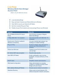
TL-SG3210<br />
JetStream L2 Lite Managed Switch<br />
Rev: 1.0.0<br />
1910010508
COPYRIGHT & TRADEMARKS<br />
Specifications are subject to change without notice.<br />
is a registered trademark of<br />
<strong>TP</strong>-LINK TECHNOLOGIES CO., LTD. Other brands and product names are trademarks or<br />
registered trademarks of their respective holders.<br />
No part of the specifications may be reproduced in any form or by any means or used to make any<br />
derivative such as translation, transformation, or adaptation without permission from <strong>TP</strong>-LINK<br />
TECHNOLOGIES CO., LTD. Copyright © 2011 <strong>TP</strong>-LINK TECHNOLOGIES CO., LTD. All rights<br />
reserved.<br />
http://www.tp-link.com<br />
FCC STATEMENT<br />
This equipment has been tested and found to comply with the limits for a Class A digital device,<br />
pursuant to part 15 of the FCC Rules. These limits are designed to provide reasonable protection<br />
against harmful interference when the equipment is operated in a commercial environment. This<br />
equipment generates, uses, and can radiate radio frequency energy and, if not installed and used<br />
in accordance with the instruction manual, may cause harmful interference to radio<br />
communications. Operation of this equipment in a residential area is likely to cause harmful<br />
interference in which case the user will be required to correct the interference at his own expense.<br />
This device complies with part 15 of the FCC Rules. Operation is subject to the following two<br />
conditions:<br />
1) This device may not cause harmful interference.<br />
2) This device must accept any interference received, including interference that may cause<br />
undesired operation.<br />
Any changes or modifications not expressly approved by the party responsible for compliance<br />
could void the user’s authority to operate the equipment.<br />
CE Mark Warning<br />
This is a class A product. In a domestic environment, this product may cause radio interference, in<br />
which case the user may be required to take adequate measures.<br />
SAFETY NOTICES<br />
Caution:<br />
Do not use this product near water, for example, in a wet basement or near a swimming pool.<br />
Avoid using this product during an electrical storm. There may be a remote risk of electric shock<br />
from lightning.<br />
III
CONTENTS<br />
Package Contents ..........................................................................................................................1<br />
Chapter 1 About this Guide...........................................................................................................2<br />
1.1 Intended Readers .........................................................................................................2<br />
1.2 Conventions..................................................................................................................2<br />
1.3 Overview of This Guide ................................................................................................2<br />
Chapter 2 Introduction ..................................................................................................................6<br />
2.1 Overview of the Switch .................................................................................................6<br />
2.2 Main Features...............................................................................................................6<br />
2.3 Appearance Description ...............................................................................................7<br />
2.3.1 Front Panel ........................................................................................................7<br />
2.3.2 Rear Panel.........................................................................................................8<br />
Chapter 3 Login to the Switch.......................................................................................................9<br />
3.1 Login.............................................................................................................................9<br />
3.2 Configuration ................................................................................................................9<br />
Chapter 4 System ....................................................................................................................... 11<br />
4.1 System Info................................................................................................................. 11<br />
4.1.1 System Summary............................................................................................. 11<br />
4.1.2 Device Description ...........................................................................................13<br />
4.1.3 System Time ....................................................................................................13<br />
4.1.4 System IP.........................................................................................................15<br />
4.2 User Manage ..............................................................................................................16<br />
4.2.1 User Table........................................................................................................16<br />
4.2.2 User Config ......................................................................................................16<br />
4.3 System Tools ..............................................................................................................18<br />
4.3.1 Config Restore .................................................................................................18<br />
4.3.2 Config Backup..................................................................................................18<br />
4.3.3 Firmware Upgrade ...........................................................................................19<br />
4.3.4 System Reboot ................................................................................................20<br />
4.3.5 System Reset...................................................................................................20<br />
4.4 Access Security ..........................................................................................................20<br />
4.4.1 Access Control.................................................................................................20<br />
4.4.2 SSL Config.......................................................................................................22<br />
4.4.3 SSH Config ......................................................................................................23<br />
Chapter 5 Switching....................................................................................................................29<br />
5.1 Port .............................................................................................................................29<br />
5.1.1 Port Config.......................................................................................................29<br />
IV
5.1.2 Port Mirror........................................................................................................30<br />
5.1.3 Port Security ....................................................................................................31<br />
5.1.4 Port Isolation....................................................................................................33<br />
5.2 LAG ............................................................................................................................34<br />
5.2.1 LAG Table ........................................................................................................34<br />
5.2.2 Static LAG........................................................................................................36<br />
5.2.3 LACP Config ....................................................................................................37<br />
5.3 Traffic Monitor.............................................................................................................39<br />
5.3.1 Traffic Summary...............................................................................................39<br />
5.3.2 Traffic Statistics ................................................................................................40<br />
5.4 MAC Address..............................................................................................................41<br />
5.4.1 Address Table ..................................................................................................42<br />
5.4.2 Static Address ..................................................................................................44<br />
5.4.3 Dynamic Address .............................................................................................45<br />
5.4.4 Filtering Address ..............................................................................................47<br />
Chapter 6 VLAN..........................................................................................................................49<br />
6.1 802.1Q VLAN..............................................................................................................50<br />
6.1.1 VLAN Config ....................................................................................................52<br />
6.1.2 Port Config.......................................................................................................54<br />
6.2 MAC VLAN .................................................................................................................55<br />
6.3 Protocol VLAN ............................................................................................................57<br />
6.3.1 Protocol Group Table .......................................................................................60<br />
6.3.2 Protocol Group.................................................................................................60<br />
6.3.3 Protocol Template ............................................................................................61<br />
6.4 Application Example for 802.1Q VLAN .......................................................................62<br />
6.5 Application Example for MAC VLAN...........................................................................64<br />
6.6 Application Example for Protocol VLAN......................................................................65<br />
6.7 GVRP .........................................................................................................................67<br />
Chapter 7 Spanning Tree............................................................................................................71<br />
7.1 S<strong>TP</strong> Config .................................................................................................................76<br />
7.1.1 S<strong>TP</strong> Config.......................................................................................................76<br />
7.1.2 S<strong>TP</strong> Summary..................................................................................................78<br />
7.2 Port Config..................................................................................................................78<br />
7.3 MS<strong>TP</strong> Instance ...........................................................................................................80<br />
7.3.1 Region Config ..................................................................................................80<br />
7.3.2 Instance Config ................................................................................................81<br />
7.3.3 Instance Port Config.........................................................................................82<br />
V
7.4 S<strong>TP</strong> Security...............................................................................................................84<br />
7.4.1 Port Protect......................................................................................................84<br />
7.4.2 TC Protect........................................................................................................86<br />
7.5 Application Example for S<strong>TP</strong> Function .......................................................................87<br />
Chapter 8 Multicast.....................................................................................................................91<br />
8.1 IGMP Snooping ..........................................................................................................93<br />
8.1.1 Snooping Config ..............................................................................................94<br />
8.1.2 Port Config.......................................................................................................95<br />
8.1.3 VLAN Config ....................................................................................................96<br />
8.1.4 Multicast VLAN ................................................................................................98<br />
8.2 Multicast IP ...............................................................................................................101<br />
8.2.1 Multicast IP Table ...........................................................................................102<br />
8.2.2 Static Multicast IP...........................................................................................102<br />
8.3 Multicast Filter...........................................................................................................103<br />
8.3.1 IP-Range........................................................................................................104<br />
8.3.2 Port Filter .......................................................................................................105<br />
8.4 Packet Statistics........................................................................................................106<br />
Chapter 9 QoS..........................................................................................................................108<br />
9.1 DiffServ..................................................................................................................... 111<br />
9.1.1 Port Priority .................................................................................................... 111<br />
9.1.2 Schedule Mode .............................................................................................. 112<br />
9.1.3 802.1P Priority ............................................................................................... 113<br />
9.1.4 DSCP Priority................................................................................................. 113<br />
9.2 Bandwidth Control .................................................................................................... 115<br />
9.2.1 Rate Limit....................................................................................................... 115<br />
9.2.2 Storm Control ................................................................................................. 116<br />
9.3 Voice VLAN .............................................................................................................. 117<br />
9.3.1 Global Config ................................................................................................. 119<br />
9.3.2 Port Config.....................................................................................................120<br />
9.3.3 OUI Config .....................................................................................................121<br />
Chapter 10 ACL ..........................................................................................................................123<br />
10.1 Time-Range ..............................................................................................................123<br />
10.1.1 Time-Range Summary ...................................................................................123<br />
10.1.2 Time-Range Create........................................................................................124<br />
10.1.3 Holiday Config................................................................................................125<br />
10.2 ACL Config ...............................................................................................................125<br />
10.2.1 ACL Summary................................................................................................126<br />
VI
10.2.2 ACL Create ....................................................................................................126<br />
10.2.3 MAC ACL .......................................................................................................127<br />
10.2.4 Standard-IP ACL ............................................................................................128<br />
10.2.5 Extend-IP ACL ...............................................................................................128<br />
10.3 Policy Config.............................................................................................................130<br />
10.3.1 Policy Summary .............................................................................................130<br />
10.3.2 Policy Create..................................................................................................131<br />
10.3.3 Action Create .................................................................................................131<br />
10.4 Policy Binding ...........................................................................................................132<br />
10.4.1 Binding Table .................................................................................................132<br />
10.4.2 Port Binding ...................................................................................................133<br />
10.4.3 VLAN Binding.................................................................................................133<br />
10.5 Application Example for ACL ....................................................................................134<br />
Chapter 11 Network Security......................................................................................................137<br />
11.1 IP-MAC Binding ........................................................................................................137<br />
11.1.1 Binding Table .................................................................................................137<br />
11.1.2 <strong>Manual</strong> Binding ..............................................................................................138<br />
11.1.3 ARP Scanning................................................................................................140<br />
11.1.4 DHCP Snooping.............................................................................................141<br />
11.2 ARP Inspection .........................................................................................................147<br />
11.2.1 ARP Detect ....................................................................................................151<br />
11.2.2 ARP Defend ...................................................................................................152<br />
11.2.3 ARP Statistics ................................................................................................153<br />
11.3 DoS Defend ..............................................................................................................154<br />
11.4 802.1X ......................................................................................................................156<br />
11.4.1 Global Config .................................................................................................159<br />
11.4.2 Port Config.....................................................................................................161<br />
11.4.3 Radius Server ................................................................................................162<br />
Chapter 12 SNMP.......................................................................................................................164<br />
12.1 SNMP Config............................................................................................................166<br />
12.1.1 Global Config .................................................................................................166<br />
12.1.2 SNMP View....................................................................................................167<br />
12.1.3 SNMP Group..................................................................................................168<br />
12.1.4 SNMP User ....................................................................................................169<br />
12.1.5 SNMP Community..........................................................................................171<br />
12.2 Notification................................................................................................................173<br />
12.3 RMON.......................................................................................................................175<br />
VII
12.3.1 History Control ...............................................................................................176<br />
12.3.2 Event Config ..................................................................................................176<br />
12.3.3 Alarm Config ..................................................................................................177<br />
Chapter 13 Cluster......................................................................................................................180<br />
13.1 NDP ..........................................................................................................................181<br />
13.1.1 Neighbor Info .................................................................................................181<br />
13.1.2 NDP Summary ...............................................................................................182<br />
13.1.3 NDP Config ....................................................................................................184<br />
13.2 NTDP........................................................................................................................184<br />
13.2.1 Device Table ..................................................................................................185<br />
13.2.2 NTDP Summary.............................................................................................186<br />
13.2.3 NTDP Config..................................................................................................187<br />
13.3 Cluster ......................................................................................................................188<br />
13.3.1 Cluster Summary ...........................................................................................188<br />
13.3.2 Cluster Config ................................................................................................190<br />
13.4 Application Example for Cluster Function .................................................................191<br />
Chapter 14 Maintenance ............................................................................................................194<br />
14.1 System Monitor.........................................................................................................194<br />
14.1.1 CPU Monitor ..................................................................................................194<br />
14.1.2 Memory Monitor .............................................................................................195<br />
14.2 Log............................................................................................................................196<br />
14.2.1 Log Table .......................................................................................................197<br />
14.2.2 Local Log .......................................................................................................198<br />
14.2.3 Remote Log ...................................................................................................198<br />
14.2.4 Backup Log ....................................................................................................199<br />
14.3 Device Diagnose.......................................................................................................200<br />
14.3.1 Cable Test ......................................................................................................200<br />
14.3.2 Loopback .......................................................................................................201<br />
14.4 Network Diagnose ....................................................................................................201<br />
14.4.1 Ping................................................................................................................201<br />
14.4.2 Tracert............................................................................................................202<br />
Appendix A: Specifications .........................................................................................................204<br />
Appendix B: Configuring the PCs ...............................................................................................205<br />
Appendix C: Load Software Using F<strong>TP</strong> ......................................................................................208<br />
Appendix D: 802.1X Client Software ..........................................................................................213<br />
Appendix E: Glossary .................................................................................................................221<br />
VIII
Package Contents<br />
The following items should be found in your box:<br />
‣ One JetStream L2 Lite Managed Switch<br />
‣ One power cord<br />
‣ One console cable<br />
‣ Two mounting brackets and other fittings<br />
‣ Installation Guide<br />
‣ Resource CD for TL-SG3210 switch, including:<br />
• This User Guide<br />
• Other Helpful Information<br />
Note:<br />
Make sure that the package contains the above items. If any of the listed items are damaged or<br />
missing, please contact with your distributor.<br />
1
Chapter 1 About this Guide<br />
This User Guide contains information for setup and management of TL-SG3210 JetStream L2 Lite<br />
Managed Switch. Please read this guide carefully before operation.<br />
1.1 Intended Readers<br />
This Guide is intended for network managers familiar with IT concepts and network terminologies.<br />
1.2 Conventions<br />
In this Guide the following conventions are used:<br />
‣ The switch or TL-SG3210 mentioned in this Guide stands for TL-SG3210 JetStream L2 Lite<br />
Managed Switch without any explanation.<br />
‣ Menu Name→Submenu Name→Tab page indicates the menu structure. System→System<br />
Info→System Summary means the System Summary page under the System Info menu<br />
option that is located under the System menu.<br />
‣ Bold font indicates a button, a toolbar icon, menu or menu item.<br />
Symbols in this Guide:<br />
Symbol<br />
Note:<br />
Tips:<br />
Description<br />
Ignoring this type of note might result in a malfunction or damage to the<br />
device.<br />
This format indicates important information that helps you make better use<br />
of your device.<br />
1.3 Overview of This Guide<br />
Chapter<br />
Chapter 1 About This Guide<br />
Chapter 2 Introduction<br />
Chapter 3 Login to the Switch<br />
Introduction<br />
Introduces the guide structure and conventions.<br />
Introduces the features, application and appearance of TL-SG3210<br />
switch.<br />
Introduces how to log on to the Web management page.<br />
2
Chapter<br />
Chapter 4 System<br />
Chapter 5 Switching<br />
Chapter 6 VLAN<br />
Chapter 7 Spanning Tree<br />
Chapter 8 Multicast<br />
Introduction<br />
This module is used to configure system properties of the switch.<br />
Here mainly introduces:<br />
• System Info: Configure the description, system time and network<br />
parameters of the switch.<br />
• User Manage: Configure the user name and password for users<br />
to log on to the Web management page with a certain access<br />
level.<br />
• System Tools: Manage the configuration file of the switch.<br />
• Access Security: Provide different security measures for the<br />
login to enhance the configuration management security.<br />
This module is used to configure basic functions of the switch. Here<br />
mainly introduces:<br />
• Port: Configure the basic features for the port.<br />
• LAG: Configure <strong>Link</strong> Aggregation Group. LAG is to combine a<br />
number of ports together to make a single high-bandwidth data<br />
path.<br />
• Traffic Monitor: Monitor the traffic of each port<br />
• MAC Address: Configure the address table of the switch.<br />
This module is used to configure VLANs to control broadcast in<br />
LANs. Here mainly introduces:<br />
• 802.1Q VLAN: Configure port-based VLAN.<br />
• MAC VLAN: Configure MAC-based VLAN without changing the<br />
802.1Q VLAN configuration.<br />
• Protocol VLAN: Create VLANs in application layer to make some<br />
special data transmitted in the specified VLAN.<br />
• GVRP: GVRP allows the switch to automatically add or remove<br />
the VLANs via the dynamic VLAN registration information and<br />
propagate the local VLAN registration information to other<br />
switches, without having to individually configure each VLAN.<br />
This module is used to configure spanning tree function of the<br />
switch. Here mainly introduces:<br />
• S<strong>TP</strong> Config: Configure and view the global settings of spanning<br />
tree function.<br />
• Port Config: Configure CIST parameters of ports.<br />
• MS<strong>TP</strong> Instance: Configure MS<strong>TP</strong> instances.<br />
• S<strong>TP</strong> Security: Configure protection function to prevent devices<br />
from any malicious attack against S<strong>TP</strong> features.<br />
This module is used to configure multicast function of the switch.<br />
Here mainly introduces:<br />
• IGMP Snooping: Configure global parameters of IGMP Snooping<br />
function, port properties, VLAN and multicast VLAN.<br />
• Multicast IP: Configure multicast IP table.<br />
• Multicast Filter: Configure multicast filter feature to restrict users<br />
ordering multicast programs.<br />
• Packet Statistics: View the multicast data traffic on each port of<br />
the switch, which facilitates you to monitor the IGMP messages<br />
in the network.<br />
3
Chapter<br />
Chapter 9 QoS<br />
Chapter 10 ACL<br />
Chapter 11 Network Security<br />
Chapter 12 SNMP<br />
Chapter 13 Cluster<br />
Introduction<br />
This module is used to configure QoS function to provide different<br />
quality of service for various network applications and<br />
requirements. Here mainly introduces:<br />
• DiffServ: Configure priorities, port priority, 802.1P priority and<br />
DSCP priority.<br />
• Bandwidth Control: Configure rate limit feature to control the<br />
traffic rate on each port; configure storm control feature to filter<br />
broadcast, multicast and UL frame in the network.<br />
• Voice VLAN: Configure voice VLAN to transmit voice data<br />
stream within the specified VLAN so as to ensure the<br />
transmission priority of voice data stream and voice quality.<br />
This module is used to configure match rules and process policies<br />
of packets to filter packets in order to control the access of the<br />
illegal users to the network. Here mainly introduces:<br />
• Time-Range: Configure the effective time for ACL rules.<br />
• ACL Config: ACL rules.<br />
• Policy Config: Configure operation policies.<br />
• Policy Binding: Bind the policy to a port/VLAN to take its effect on<br />
a specific port/VLAN.<br />
This module is used to configure the multiple protection measures<br />
for the network security. Here mainly introduces:<br />
• IP-MAC Binding: Bind the IP address, MAC address, VLAN ID<br />
and the connected Port number of the Host together.<br />
• ARP Inspection: Configure ARP inspection feature to prevent the<br />
network from ARP attacks.<br />
• DoS Defend: Configure DoS defend feature to prevent DoS<br />
attack.<br />
• 802.1X: Configure common access control mechanism for LAN<br />
ports to solve mainly authentication and security problems.<br />
This module is used to configure SNMP function to provide a<br />
management frame to monitor and maintain the network devices.<br />
Here mainly introduces:<br />
• SNMP Config: Configure global settings of SNMP function.<br />
• Notification: Configure notification function for the management<br />
station to monitor and process the events.<br />
• RMON: Configure RMON function to monitor network more<br />
efficiently.<br />
This module is used to configure cluster function to central manage<br />
the scattered devices in the network. Here mainly introduces:<br />
• NDP: Configure NDP function to get the information of the directly<br />
connected neighbor devices.<br />
• NTDP: Configure NTDP function for the commander switch to<br />
collect NDP information.<br />
• Cluster: Configure cluster function to establish and maintain<br />
cluster.<br />
4
Chapter<br />
Chapter 14 Maintenance<br />
Appendix A Specifications<br />
Appendix B Configure the PCs<br />
Appendix C System<br />
Maintenance via F<strong>TP</strong><br />
Appendix D 802.1X Client<br />
Software<br />
Appendix E Glossary<br />
Introduction<br />
This module is used to assemble the commonly used system tools<br />
to manage the switch. Here mainly introduces:<br />
• System Monitor: Monitor the memory and CPU of the switch.<br />
• Log: View configuration parameters on the switch.<br />
• Device Diagnose: Test the connection status of the cable<br />
connected to the switch, test if the port of the switch and the<br />
connected device are available.<br />
• Network Diagnose: Test if the destination is reachable and the<br />
account of router hops from the switch to the destination.<br />
Lists the hardware specifications of the Switch.<br />
Introduces how to configure the PCs.<br />
Introduces how to load software of the switch using F<strong>TP</strong> function.<br />
Introduces how to use 802.1X Client Software provided for<br />
authentication.<br />
Lists the glossary used in this manual.<br />
Return to CONTENTS<br />
5
Chapter 2 Introduction<br />
Thanks for choosing the TL-SG3210 JetStream L2 Lite Managed Switch!<br />
2.1 Overview of the Switch<br />
Designed for workgroups and departments, TL-SG3210 from <strong>TP</strong>-LINK provides wire-speed<br />
performance and abundant layer 2 management features. It provides a variety of service features<br />
and multiple powerful functions with high security.<br />
The EIA-standardized framework and smart configuration capacity can provide flexible solutions<br />
for a variable scale of networks. ACL, 802.1x and Dynamic ARP Inspection provide robust security<br />
strategies. QoS and IGMP snooping/filtering optimize voice and video application. <strong>Link</strong><br />
aggregation (LACP) increases aggregated bandwidth, optimizing the transport of business critical<br />
data. SNMP, RMON, WEB/CLI/Telnet Log-in bring abundant management policies. TL-SG3210<br />
Switch integrates multiple functions with excellent performance, and is friendly to manage, which<br />
can fully meet the need of the users demanding higher networking performance.<br />
2.2 Main Features<br />
• Resiliency and Availability<br />
+ <strong>Link</strong> aggregation (LACP) increases aggregated bandwidth, optimizing the transport of<br />
business critical data.<br />
+ IEEE 802.1s Multiple Spanning Tree provides high link availability in multiple VLAN<br />
environments.<br />
+ Multicast snooping automatically prevents flooding of IP multicast traffic.<br />
+ Root Guard protects root bridge from malicious attack or configuration mistakes<br />
• Layer 2 Switching<br />
+ GVRP (GARP VLAN Registration Protocol) allows automatic learning and dynamic<br />
assignment of VLANs.<br />
+ Supports 255 active VLAN groups and 4K VLAN IDs.<br />
• Quality of Service<br />
+ Supports L2/L3 granular CoS with 4 priority queues per port.<br />
+ Rate limiting confines the traffic flow accurately according to the preset value.<br />
• Security<br />
+ Supports multiple industry standard user authentication methods such as 802.1x, RADIUS.<br />
+ Dynamic ARP Inspection blocks ARP packets from unauthorized hosts, preventing<br />
man-in-the-middle attacks.<br />
+ L2/L3/L4 Access Control Lists restrict untrusted access to the protected resource.<br />
+ Provides SSHv1/v2, SSL 2.0/3.0 and TLS v1 for access encryption.<br />
• Manageability<br />
+ IP Clustering provides high scalability and easy Single-IP-Management.<br />
+ Supports Telnet, CLI, SNMP v1/v2c/v3, RMON and web access.<br />
+ Port Mirroring enables monitoring selected ingress/egress traffic.<br />
6
2.3 Appearance Description<br />
2.3.1 Front Panel<br />
Figure 2-1 Front Panel<br />
The following parts are located on the front panel of the Switch:<br />
‣ 10/100/1000Mbps Ports: Designed to connect to the device with a bandwidth of 10Mbps,<br />
100Mbps or 1000Mbps. Each has a corresponding 1000Mbps LED.<br />
‣ SFP Ports: Designed to install the SFP module.<br />
‣ Console Port: Designed to connect with the serial port of a computer or terminal for monitoring<br />
and configuring the Switch.<br />
‣ LEDs<br />
Name Status Indication<br />
Power<br />
System<br />
1000Mbps<br />
<strong>Link</strong>/Act<br />
On<br />
Flashing<br />
Off<br />
On<br />
Flashing<br />
Off<br />
On<br />
Off<br />
On<br />
Flashing<br />
Off<br />
Power is on.<br />
Power supply is abnormal.<br />
Power is off or power supply is abnormal.<br />
The Switch is working abnormally.<br />
The Switch is working normally.<br />
The Switch is working abnormally.<br />
A 1000Mbps device is connected to the corresponding<br />
port.<br />
A 10/100Mbps device or no device is connected to the<br />
corresponding port.<br />
A device is connected to the corresponding port, but not<br />
activity.<br />
Data is being transmitted or received.<br />
No device is connected to the corresponding port.<br />
7
2.3.2 Rear Panel<br />
The rear panel of TL-SG3210 features a power socket and a Grounding Terminal (marked with ).<br />
Figure 2-2 Rear Panel<br />
‣ Grounding Terminal: TL-SG3210 already comes with Lightning Protection Mechanism. You<br />
can also ground the Switch through the PE (Protecting Earth) cable of AC cord or with Ground<br />
Cable. For detail information, please refer to Installation Guide.<br />
‣ AC Power Socket: Connect the female connector of the power cord here, and the male<br />
connector to the AC power outlet. Please make sure the voltage of the power supply meets the<br />
requirement of the input voltage (100-240V~ 50/60Hz 0.6A).<br />
Return to CONTENTS<br />
8
3.1 Login<br />
Chapter 3 Login to the Switch<br />
1) To access the configuration utility, open a web-browser and type in the default address<br />
http://192.168.0.1 in the address field of the browser, then press the Enter key.<br />
Figure 3-1 Web-browser<br />
Tips:<br />
To log in to the Switch, the IP address of your PC should be set in the same subnet addresses of<br />
the Switch. The IP address is 192.168.0.x ("x" is any number from 2 to 254), Subnet Mask is<br />
255.255.255.0. For the detailed instructions as to how to do this, please refer to Appendix B.<br />
2) After a moment, a login window will appear, as shown in Figure 3-2. Enter admin for the User<br />
Name and Password, both in lower case letters. Then click the Login button or press the Enter<br />
key.<br />
3.2 Configuration<br />
Figure 3-2 Login<br />
After a successful login, the main page will appear as Figure 3-3, and you can configure the<br />
function by clicking the setup menu on the left side of the screen.<br />
9
Figure 3-3 Main Setup-Menu<br />
Note:<br />
Clicking Apply can only make the new configurations effective before the switch is rebooted. If<br />
you want to keep the configurations effective even the switch is rebooted, please click Saving<br />
Config. You are suggested to click Saving Config before cutting off the power or rebooting the<br />
switch to avoid losing the new configurations.<br />
Return to CONTENTS<br />
10
Chapter 4 System<br />
The System module is mainly for system configuration of the switch, including four submenus:<br />
System Info, User Manage, System Tools and Access Security.<br />
4.1 System Info<br />
The System Info, mainly for basic properties configuration, can be implemented on System<br />
Summary, Device Description, System Time and System IP pages.<br />
4.1.1 System Summary<br />
On this page you can view the port connection status and the system information.<br />
The port status diagram shows the working status of 8 10/100/1000Mbps RJ45 ports and 2 SFP<br />
ports of the switch. The ports labeled as numbers are 10/100/1000Mbps ports; the ports labeled as<br />
SFP are SFP ports.<br />
Choose the menu System→System Info→System Summary to load the following page.<br />
‣ Port Status<br />
Figure 4-1 System Summary<br />
Indicates the 1000Mbps port is not connected to a device.<br />
Indicates the 1000Mbps port is at the speed of 1000Mbps.<br />
Indicates the 1000Mbps port is at the speed of 10Mbps or 100Mbps.<br />
11
Indicates the SFP port is not connected to a device.<br />
Indicates the SFP port is at the speed of 1000Mbps.<br />
Indicates the SFP port is at the speed of 100Mbps.<br />
When the cursor moves on the port, the detailed information of the port will be displayed.<br />
‣ Port Info<br />
Figure 4-2 Port Information<br />
Port:<br />
Type:<br />
Rate:<br />
Status:<br />
Displays the port number of the switch.<br />
Displays the type of the port.<br />
Displays the maximum transmission rate of the port.<br />
Displays the connection status of the port.<br />
Click a port to display the bandwidth utilization on this port. The actual rate divided by theoretical<br />
maximum rate is the bandwidth utilization. Figure 4-3 displays the bandwidth utilization monitored<br />
every four seconds. Monitoring the bandwidth utilization on each port facilitates you to monitor the<br />
network traffic and analyze the network abnormities.<br />
‣ Bandwidth Utilization<br />
Figure 4-3 Bandwidth Utilization<br />
12
Rx:<br />
Tx:<br />
Select Rx to display the bandwidth utilization of receiving packets<br />
on this port.<br />
Select Tx to display the bandwidth utilization of sending packets<br />
on this port.<br />
4.1.2 Device Description<br />
On this page you can configure the description of the switch, including device name, device location<br />
and system contact.<br />
Choose the menu System→System Info→Device Description to load the following page.<br />
Figure 4-4 Device Description<br />
The following entries are displayed on this screen:<br />
‣ Device Description<br />
Device Name:<br />
Device Location:<br />
System Contact:<br />
Enter the name of the switch.<br />
Enter the location of the switch.<br />
Enter your contact information.<br />
4.1.3 System Time<br />
System Time is the time displayed while the switch is running. On this page you can configure the<br />
system time and the settings here will be used for other time-based functions like ACL.<br />
You can manually set the system time, get GMT automatically if it has connected to a N<strong>TP</strong> server or<br />
synchronize with PC’s clock as the system time.<br />
Choose the menu System→System Info→System Time to load the following page.<br />
13
Figure 4-5 System Time<br />
The following entries are displayed on this screen:<br />
‣ Time Info<br />
Current System Date:<br />
Current Time Source:<br />
Displays the current date and time of the switch.<br />
Displays the current time source of the switch.<br />
‣ Time Config<br />
<strong>Manual</strong>:<br />
Get GMT:<br />
Synchronize<br />
PC’S Clock:<br />
‣ DST Config<br />
DST Status:<br />
Start Time:<br />
End Time:<br />
with<br />
When this option is selected, you can set the date and time<br />
manually.<br />
When this option is selected, you can configure the time zone and<br />
the IP Address for the N<strong>TP</strong> Server. The switch will get GMT<br />
automatically if it has connected to a N<strong>TP</strong> Server.<br />
• Time Zone: Select your local time.<br />
• Primary/Secondary N<strong>TP</strong> Server: Enter the IP Address for the<br />
N<strong>TP</strong> Server.<br />
When this option is selected, the administrator PC’s clock is<br />
utilized.<br />
Enable or Disable DST.<br />
Select the Start Time of DST.<br />
Select the End Time of DST.<br />
14
Note:<br />
When Get GMT is selected and the switch failed to get time from the configured time server, the<br />
switch will change to get time from the latest time server from which you got time successfully or<br />
from the public time server in its default network.<br />
4.1.4 System IP<br />
Each device in the network possesses a unique IP Address. You can log on to the Web<br />
management page to operate the switch using this IP Address. The switch supports three modes<br />
to obtain an IP address: Static IP, DHCP and BOO<strong>TP</strong>. The IP address obtained using a new mode<br />
will replace the original IP address. On this page you can configure the system IP of the switch.<br />
Choose the menu System→System Info→System IP to load the following page.<br />
Figure 4-6 System IP<br />
The following entries are displayed on this screen:<br />
‣ IP Config<br />
MAC Address:<br />
IP Address Mode:<br />
Management VLAN:<br />
IP Address:<br />
Displays MAC Address of the switch.<br />
Select the mode to obtain IP Address for the switch.<br />
• Static IP: When this option is selected, you should enter IP<br />
Address, Subnet Mask and Default Gateway manually.<br />
• DHCP: When this option is selected, the switch will obtain<br />
network parameters from the DHCP Server.<br />
• BOO<strong>TP</strong>: When this option is selected, the switch will obtain<br />
network parameters from the BOO<strong>TP</strong> Server.<br />
Enter the ID of management VLAN, the only VLAN through which<br />
you can get access to the switch. By default VLAN1 owning all the<br />
ports is the Management VLAN and you can access the switch via<br />
any port on the switch. However, if another VLAN is created and<br />
set to be the Management VLAN, you may have to reconnect the<br />
management station to a port that is a member of the<br />
Management VLAN.<br />
Enter the system IP of the switch. The default system IP is<br />
192.168.0.1 and you can change it appropriate to your needs.<br />
15
Subnet Mask:<br />
Default Gateway:<br />
Enter the subnet mask of the switch.<br />
Enter the default gateway of the switch.<br />
Note:<br />
1. Changing the IP address to a different IP segment will interrupt the network communication,<br />
so please keep the new IP address in the same IP segment with the local network.<br />
2. The switch only possesses an IP address. The IP address configured will replace the original<br />
IP address.<br />
3. If the switch gets the IP address from DHCP server, you can see the configuration of the<br />
switch in the DHCP server; if DHCP option is selected but no DHCP server exists in the<br />
network, the switch will keep obtaining IP address from DHCP server until success.<br />
4. If DHCP or BOO<strong>TP</strong> option is selected, the switch will get network parameters dynamically<br />
from the Internet, so IP address, subnet mask and default gateway can not be configured.<br />
5. By default, the default IP address is 192.168.0.1.<br />
4.2 User Manage<br />
User Manage functions to configure the user name and password for users to log on to the Web<br />
management page with a certain access level so as to protect the settings of the switch from being<br />
randomly changed.<br />
The User Manage function can be implemented on User Table and User Config pages.<br />
4.2.1 User Table<br />
On this page you can view the information about the current users of the switch.<br />
Choose the menu System→User Manage→User Table to load the following page.<br />
4.2.2 User Config<br />
Figure 4-7 User Table<br />
On this page you can configure the access level of the user to log on to the Web management<br />
page. The switch provides two access levels: Guest and Admin. The guest only can view the<br />
settings without the right to configure the switch; the admin can configure all the functions of the<br />
switch. The Web management pages contained in this guide are subject to the admin’s login without any<br />
explanation.<br />
Choose the menu System→User Manage→User Config to load the following page.<br />
16
Figure 4-8 User Config<br />
The following entries are displayed on this screen:<br />
‣ User Info<br />
User Name:<br />
Access Level:<br />
User Status:<br />
Password:<br />
Confirm Password:<br />
Create a name for users’ login.<br />
Select the access level to login.<br />
• Admin: Admin can edit, modify and view all the settings of<br />
different functions.<br />
• Guest: Guest only can view the settings without the right to edit<br />
and modify.<br />
Select Enable/Disable the user configuration.<br />
Type a password for users’ login.<br />
Retype the password.<br />
‣ User Table<br />
Select:<br />
User ID, Name,<br />
Access Level and<br />
status:<br />
Operation:<br />
Select the desired entry to delete the corresponding user<br />
information. It is multi-optional The current user information can’t<br />
be deleted.<br />
Displays the current user ID, user name, access level and user<br />
status.<br />
Click the Edit button of the desired entry, and you can edit the<br />
corresponding user information. After modifying the settings,<br />
please click the Modify button to make the modification effective.<br />
Access level and user status of the current user information can’t<br />
be modified.<br />
17
4.3 System Tools<br />
The System Tools function, allowing you to manage the configuration file of the switch, can be<br />
implemented on Config Restore, Config Backup, Firmware Upgrade, System Reboot and<br />
System Reset pages.<br />
4.3.1 Config Restore<br />
On this page you can upload a backup configuration file to restore your switch to this previous<br />
configuration.<br />
Choose the menu System→System Tools→Config Restore to load the following page.<br />
Figure 4-9 Config Restore<br />
The following entries are displayed on this screen:<br />
‣ Config Restore<br />
Restore Config:<br />
Click the Restore Config button to restore the backup<br />
configuration file. It will take effect after the switch automatically<br />
reboots.<br />
Note:<br />
1. It will take a few minutes to restore the configuration. Please wait without any operation.<br />
2. To avoid any damage, please don’t power down the switch while being restored.<br />
3. After being restored, the current settings of the switch will be lost. Wrong uploaded<br />
configuration file may cause the switch unmanaged.<br />
4.3.2 Config Backup<br />
On this page you can download the current configuration and save it as a file to your computer for<br />
your future configuration restore.<br />
Choose the menu System→System Tools→Config Backup to load the following page.<br />
18
Figure 4-10 Config Backup<br />
The following entries are displayed on this screen:<br />
‣ Config Backup<br />
Backup Config:<br />
Click the Backup Config button to save the current configuration<br />
as a file to your computer. You are suggested to take this measure<br />
before upgrading.<br />
Note:<br />
It will take a few minutes to backup the configuration. Please wait without any operation.<br />
4.3.3 Firmware Upgrade<br />
The switch system can be upgraded via the Web management page. To upgrade the system is to<br />
get more functions and better performance. Go to http://www.tp-link.com to download the updated<br />
firmware.<br />
Choose the menu System→System Tools→Firmware Upgrade to load the following page.<br />
Figure 4-11 Firmware Upgrade<br />
Note:<br />
1. Don’t interrupt the upgrade.<br />
2. Please select the proper software version matching with your hardware to upgrade.<br />
3. To avoid damage, please don't turn off the device while upgrading.<br />
19
4. After upgrading, the device will reboot automatically.<br />
5. You are suggested to backup the configuration before upgrading.<br />
4.3.4 System Reboot<br />
On this page you can reboot the switch and return to the login page. Please save the current<br />
configuration before rebooting to avoid loosing the configuration unsaved<br />
Choose the menu System→System Tools→System Reboot to load the following page.<br />
Figure 4-12 System Reboot<br />
Note:<br />
To avoid damage, please don't turn off the device while rebooting.<br />
4.3.5 System Reset<br />
On this page you can reset the switch to the default. All the settings will be cleared after the switch<br />
is reset.<br />
Choose the menu System→System Tools→System Reset to load the following page.<br />
Figure 4-13 System Reset<br />
Note:<br />
After the system is reset, the switch will be reset to the default and all the settings will be cleared.<br />
4.4 Access Security<br />
Access Security provides different security measures for the remote login so as to enhance the<br />
configuration management security. It can be implemented on Access Control, SSL Config and<br />
SSH Config pages.<br />
4.4.1 Access Control<br />
On this page you can control the users logging on to the Web management page to enhance the<br />
configuration management security. The definitions of Admin and Guest refer to 1.2 User Manage<br />
Choose the menu System→Access Security→Access Control to load the following page.<br />
20
Figure 4-14 Access Control<br />
The following entries are displayed on this screen:<br />
‣ Access Control Config<br />
Control Mode:<br />
IP Address&Mask<br />
MAC Address:<br />
Port:<br />
Select the control mode for users to log on to the Web<br />
management page.<br />
• IP-based: Select this option to limit the IP-range of the users for<br />
login.<br />
• MAC-based: Select this option to limit the MAC Address of the<br />
users for login.<br />
• Port-based: Select this option to limit the ports for login.<br />
These fields can be available for configuration only when IP-based<br />
mode is selected. Only the users within the IP-range you set here<br />
are allowed for login.<br />
The field can be available for configuration only when MAC-based<br />
mode is selected. Only the user with this MAC Address you set<br />
here is allowed for login.<br />
The field can be available for configuration only when Port-based<br />
mode is selected. Only the users connected to these ports you set<br />
here are allowed for login.<br />
‣ Session Config<br />
21
Session Timeout:<br />
If you do nothing with the Web management page within the<br />
timeout time, the system will log out automatically. If you want to<br />
reconfigure, please login again.<br />
‣ Access User Number<br />
Number Control;<br />
Admin Number:<br />
Guest Number:<br />
Select Enable/Disable the Number Control function.<br />
Enter the maximum number of the users logging on to the Web<br />
management page as Admin.<br />
Enter the maximum number of the users logging on to the Web<br />
management page as Guest.<br />
4.4.2 SSL Config<br />
SSL (Secure Sockets Layer), a security protocol, is to provide a secure connection for the<br />
application layer protocol (e.g. HT<strong>TP</strong>) communication based on TCP. SSL is widely used to secure<br />
the data transmission between the Web browser and servers. It is mainly applied through<br />
ecommerce and online banking.<br />
SSL mainly provides the following services:<br />
1. Authenticate the users and the servers based on the certificates to ensure the data are<br />
transmitted to the correct users and servers;<br />
2. Encrypt the data transmission to prevent the data being intercepted;<br />
3. Maintain the integrality of the data to prevent the data being altered in the transmission.<br />
Adopting asymmetrical encryption technology, SSL uses key pair to encrypt/decrypt information. A<br />
key pair refers to a public key (contained in the certificate) and its corresponding private key. By<br />
default the switch has a certificate (self-signed certificate) and a corresponding private key. The<br />
Certificate/Key Download function enables the user to replace the default key pair.<br />
After SSL is effective, you can log on to the Web management page via https://192.168.0.1. For<br />
the first time you use HT<strong>TP</strong>S connection to log into the switch with the default certificate, you will<br />
be prompted that “The security certificate presented by this website was not issued by a trusted<br />
certificate authority” or “Certificate Errors”. Please add this certificate to trusted certificates or<br />
continue to this website.<br />
On this page you can configure the SSL function.<br />
Choose the menu System→Access Security→SSL Config to load the following page.<br />
22
Figure 4-15 SSL Config<br />
The following entries are displayed on this screen:<br />
‣ Global Config<br />
SSL:<br />
Select Enable/Disable the SSL function on the switch.<br />
‣ Certificate Download<br />
Certificate File:<br />
Select the desired certificate to download to the switch. The<br />
certificate must be BASE64 encoded.<br />
‣ Key Download<br />
Key File:<br />
Select the desired SSL Key to download to the switch. The key<br />
must be BASE64 encoded.<br />
Note:<br />
1. The SSL certificate and key downloaded must match each other; otherwise the HT<strong>TP</strong>S<br />
connection will not work.<br />
2. The SSL certificate and key downloaded will not take effect until the switch is rebooted.<br />
3. To establish a secured connection using https, please enter https:// into the URL field of the<br />
browser.<br />
4. It may take more time for https connection than that for http connection, because https<br />
connection involves authentication, encryption and decryption etc.<br />
4.4.3 SSH Config<br />
As stipulated by IETF (Internet Engineering Task Force), SSH (Secure Shell) is a security protocol<br />
established on application and transport layers. SSH-encrypted-connection is similar to a telnet<br />
connection, but essentially the old telnet remote management method is not safe, because the<br />
password and data transmitted with plain-text can be easily intercepted. SSH can provide<br />
information security and powerful authentication when you log on to the switch remotely through<br />
an insecure network environment. It can encrypt all the transmission data and prevent the<br />
23
information in a remote management being leaked.<br />
Comprising server and client, SSH has two versions, V1 and V2 which are not compatible with<br />
each other. In the communication, SSH server and client can auto-negotiate the SSH version and<br />
the encryption algorithm. After getting a successful negotiation, the client sends authentication<br />
request to the server for login, and then the two can communicate with each other after successful<br />
authentication. This switch supports SSH server and you can log on to the switch via SSH<br />
connection using SSH client software.<br />
SSH key can be downloaded into the switch. If the key is successfully downloaded, the certificate<br />
authentication will be preferred for SSH access to the switch.<br />
Choose the menu System→Access Seurity→SSH Config to load the following page.<br />
Figure 4-16 SSH Config<br />
The following entries are displayed on this screen:<br />
‣ Global Config<br />
SSH:<br />
Protocol V1:<br />
Protocol V2:<br />
Idle Timeout:<br />
Max Connect:<br />
Select Enable/Disable SSH function.<br />
Select Enable/Disable SSH V1 to be the supported protocol.<br />
Select Enable/Disable SSH V2 to be the supported protocol.<br />
Specify the idle timeout time. The system will automatically<br />
release the connection when the time is up. The default time is<br />
500 seconds.<br />
Specify the maximum number of the connections to the SSH<br />
server. No new connection will be established when the number of<br />
the connections reaches the maximum number you set. The<br />
default value is 5.<br />
‣ Key Download<br />
24
Key Type:<br />
Key File:<br />
Download:<br />
Select the type of SSH Key to download. The switch supports<br />
three types: SSH-1 RSA, SSH-2 RSA and SSH-2 DSA.<br />
Select the desired key file to download.<br />
Click the Download button to download the desired key file to the<br />
switch.<br />
Note:<br />
1. Please ensure the key length of the downloaded file is in the range of 256 to 3072 bits.<br />
2. After the Key File is downloaded, the user’s original key of the same type will be replaced.<br />
The wrong uploaded file will result in the SSH access to the switch via Password<br />
authentication.<br />
Application Example 1 for SSH:<br />
‣ Network Requirements<br />
1. Log on to the switch via password authentication using SSH and the SSH function is enabled<br />
on the switch.<br />
2. PuTTY client software is recommended.<br />
‣ Configuration Procedure<br />
1. Open the software to log on to the interface of PuTTY. Enter the IP address of the switch into<br />
Host Name field; keep the default value 22 in the Port field; select SSH as the Connection<br />
type.<br />
2. Click the Open button in the above figure to log on to the switch. Enter the login user name and<br />
password, and then you can continue to configure the switch.<br />
25
Application Example 2 for SSH:<br />
‣ Network Requirements<br />
1. Log on to the switch via password authentication using SSH and the SSH function is enabled<br />
on the switch.<br />
2. PuTTY client software is recommended.<br />
‣ Configuration Procedure<br />
1. Select the key type and key length, and generate SSH key.<br />
Note:<br />
1. The key length is in the range of 256 to 3072 bits.<br />
2. During the key generation, randomly moving the mouse quickly can accelerate the key<br />
generation.<br />
2. After the key is successfully generated, please save the public key and private key to the<br />
computer.<br />
26
3. On the Web management page of the switch, download the public key file saved in the<br />
computer to the switch.<br />
Note:<br />
1. The key type should accord with the type of the key file.<br />
2. The SSH key downloading can not be interrupted.<br />
4. Download the private key file to SSH client software.<br />
27
5. After the public key and private key are downloaded, please log on to the interface of PuTTY<br />
and enter the IP address for login.<br />
After successful authentication, please enter the login user name. If you log on to the switch<br />
without entering password, it indicates that the key has been successfully downloaded.<br />
Return to CONTENTS<br />
28
Chapter 5 Switching<br />
Switching module is used to configure the basic functions of the switch, including four submenus:<br />
Port, LAG, Traffic Monitor and MAC Address.<br />
5.1 Port<br />
The Port function, allowing you to configure the basic features for the port, is implemented on the<br />
Port Config, Port Mirror,Port Security and Port Isolation pages.<br />
5.1.1 Port Config<br />
On this page, you can configure the basic parameters for the ports. When the port is disabled, the<br />
packets on the port will be discarded. Disabling the port which is vacant for a long time can reduce<br />
the power consumption effectively. And you can enable the port when it is in need.<br />
The parameters will affect the working mode of the port, please set the parameters appropriate to<br />
your needs.<br />
Choose the menu Switching→Port→Port Config to load the following page.<br />
Figure 5-1 Port Config<br />
Here you can view and configure the port parameters.<br />
Port Select:<br />
Select:<br />
Port:<br />
Description:<br />
Status:<br />
Click the Select button to quick-select the corresponding port<br />
based on the port number you entered.<br />
Select the desired port for configuration. It is multi-optional.<br />
Displays the port number.<br />
Give a description to the port for identification.<br />
Allows you to Enable/Disable the port. When Enable is<br />
29
selected, the port can forward the packets normally.<br />
Speed and Duplex:<br />
Flow Control:<br />
LAG:<br />
Select the Speed and Duplex mode for the port. The device<br />
connected to the switch should be in the same Speed and<br />
Duplex mode with the switch. When “Auto” is selected, the<br />
Speed and Duplex mode will be determined by<br />
auto-negotiation. For the SFP port, this Switch does not support<br />
auto-negotiation.<br />
Allows you to Enable/Disable the Flow Control feature. When<br />
Flow Control is enabled, the switch can synchronize the speed<br />
with its peer to avoid the packet loss caused by congestion.<br />
Displays the LAG number which the port belongs to.<br />
Note:<br />
1. The switch can not be managed through the disabled port. Please enable the port which is<br />
used to manage the switch.<br />
2. The parameters of the port members in a LAG should be set as the same.<br />
5.1.2 Port Mirror<br />
Port Mirror, the packets obtaining technology, functions to forward copies of packets from<br />
one/multiple ports (mirrored port) to a specific port (mirroring port). Usually, the mirroring port is<br />
connected to a data diagnose device, which is used to analyze the mirrored packets for monitoring<br />
and troubleshooting the network.<br />
Choose the menu Switching→Port→Port Mirror to load the following page.<br />
Figure 5-2 Mirroring Port<br />
The following entries are displayed on this screen.<br />
‣ Mirror Group List<br />
Group:<br />
Mirroring:<br />
Mode:<br />
Mirrored Port:<br />
Operation:<br />
Displays the mirror group number.<br />
Displays the mirroring port number.<br />
Displays the mirror mode, the value can be "Ingress", "Egress",<br />
"Both" or "None".<br />
Displays the mirrored ports.<br />
Click Edit to configure the mirror group.<br />
30
Click Edit to display the following figure.<br />
Figure 5-3 Mirroring Port<br />
The following entries are displayed on this screen.<br />
‣ Mirror Group<br />
Number:<br />
Select the mirror group number you want to configure.<br />
‣ Mirroring Port Config<br />
Number:<br />
Mirror Mode:<br />
Select the mirroring port number.<br />
Select the mirror mode. If you select None, the selected mirrored<br />
ports will be removed from the current mirror group.<br />
‣ Mirrored Port<br />
Here you can select the mirrored ports.<br />
Note:<br />
1. The LAG member can not be selected as the mirrored port or mirroring port.<br />
2. A port can not be set as the mirrored port and the mirroring port simultaneously.<br />
3. The Port Mirror function can take effect span the multiple VLANs.<br />
5.1.3 Port Security<br />
MAC Address Table maintains the mapping relationship between the port and the MAC address of<br />
the connected device, which is the base of the packet forwarding. The capacity of MAC Address<br />
Table is fixed. MAC Address Attack is the attack method that the attacker takes to obtain the<br />
31
network information illegally. The attacker uses tools to generate the cheating MAC address and<br />
quickly occupy the MAC Address Table. When the MAC Address Table is full, the switch will<br />
broadcast the packets to all the ports. At this moment, the attacker can obtain the network<br />
information via various sniffers and attacks. When the MAC Address Table is full, the packets<br />
traffic will flood to all the ports, which results in overload, lower speed, packets drop and even<br />
breakdown of the system.<br />
Port Security is to protect the switch from the malicious MAC Address Attack by limiting the<br />
maximum number of MAC addresses that can be learned on the port. The port with Port Security<br />
feature enabled will learn the MAC address dynamically. When the learned MAC address number<br />
reaches the maximum, the port will stop learning. Thereafter, the other devices with the MAC<br />
address unlearned can not access to the network via this port.<br />
Choose the menu Switching→Port→Port Security to load the following page.<br />
Figure 5-4 Port Security<br />
The following entries are displayed on this screen:<br />
‣ Port Security<br />
Select:<br />
Port:<br />
Max Learned MAC:<br />
Learned Num:<br />
Learn Mode:<br />
Select the desired port for Port Security configuration. It is<br />
multi-optional.<br />
Displays the port number.<br />
Specify the maximum number of MAC addresses that can be<br />
learned on the port.<br />
Displays the number of MAC addresses that have been learned<br />
on the port.<br />
Select the Learn Mode for the port.<br />
• Dynamic: When Dynamic mode is selected, the learned<br />
MAC address will be deleted automatically after the aging<br />
32
time.<br />
• Static: When Static mode is selected, the learned MAC<br />
address will be out of the influence of the aging time and<br />
can only be deleted manually. The learned entries will be<br />
cleared after the switch is rebooted.<br />
• Permanent: When Permanent mode is selected, the<br />
learned MAC address will be out of the influence of the<br />
aging time and can only be deleted manually. The learned<br />
entries will be saved even the switch is rebooted.<br />
Status:<br />
Select Enable/Disable the Port Security feature for the port.<br />
Note:<br />
1. The Port Security function is disabled for the LAG port member. Only the port is removed from<br />
the LAG, will the Port Security function be available for the port.<br />
2. The Port Security function is disabled when the 802.1X function is enabled.<br />
5.1.4 Port Isolation<br />
Port Isolation provides a method of restricting traffic flow to improve the network security by<br />
forbidding the port to forward packets to the ports that are not on its forward portlist.<br />
Choose the menu “Switching→Port→Port Isolation” to load the following page.<br />
Figure 5-5 Port Isolation Config<br />
The following entries are displayed on this screen:<br />
‣ Port Isolation Config<br />
Port:<br />
Select the port number to set its forwardlist.<br />
33
Forward Portlist:<br />
Select the port that to be forwarded to.<br />
‣ Port Isolation List<br />
Port:<br />
Forward Portlist:<br />
Display the port number.<br />
Display the forwardlist.<br />
5.2 LAG<br />
LAG (<strong>Link</strong> Aggregation Group) is to combine a number of ports together to make a single<br />
high-bandwidth data path, so as to implement the traffic load sharing among the member ports in<br />
the group and to enhance the connection reliability.<br />
For the member ports in an aggregation group, their basic configuration must be the same. The<br />
basic configuration includes S<strong>TP</strong>, QoS, GVRP, VLAN, port attributes, MAC Address Learning<br />
mode and other associated settings. The further explains are following:<br />
• If the ports, which are enabled for the GVRP, 802.1Q VLAN, Voice VLAN, S<strong>TP</strong>, QoS, DHCP<br />
Snooping and Port Configuration (Speed and Duplex, Flow Control), are in a LAG, their<br />
configurations should be the same.<br />
• The ports, which are enabled for the Port Security, Port Mirror, MAC Address Filtering,<br />
Static MAC Address Binding and 802.1X Authentication, can not be added to the LAG.<br />
• It’s not suggested to add the ports with ARP Inspection and DoS Defend enabled to the<br />
LAG.<br />
If the LAG is needed, you are suggested to configure the LAG function here before configuring the<br />
other functions for the member ports.<br />
Tips:<br />
1. Calculate the bandwidth for a LAG: If a LAG consists of the four ports in the speed of<br />
1000Mbps Full Duplex, the whole bandwidth of the LAG is up to 8000Mbps (2000Mbps * 4)<br />
because the bandwidth of each member port is 2000Mbps counting the up-linked speed of<br />
1000Mbps and the down-linked speed of 1000Mbps.<br />
2. The traffic load of the LAG will be balanced among the ports according to the Aggregate<br />
Arithmetic. If the connections of one or several ports are broken, the traffic of these ports will<br />
be transmitted on the normal ports, so as to guarantee the connection reliability.<br />
Depending on different aggregation modes, aggregation groups fall into two types: Static LAG<br />
and LACP Config. The LAG function is implemented on the LAG Table, Static LAG and LACP<br />
Config configuration pages.<br />
5.2.1 LAG Table<br />
On this page, you can view the information of the current LAG of the switch.<br />
Choose the menu Switching→LAG→LAG Table to load the following page.<br />
34
Figure 5-6 LAG Table<br />
The following entries are displayed on this screen:<br />
‣ Global Config<br />
Aggregate Arithmetic:<br />
Select the applied scope of Aggregate Arithmetic, which<br />
results in choosing a port to transfer the packets.<br />
• SRC MAC + DST MAC: When this option is selected,<br />
the Aggregate Arithmetic will apply to the source and<br />
destination MAC addresses of the packets.<br />
• SRC IP + DST IP: When this option is selected, the<br />
Aggregate Arithmetic will apply to the source and<br />
destination IP addresses of the packets.<br />
‣ LAG Table<br />
Select:<br />
Group Number:<br />
Description:<br />
Member:<br />
Operation:<br />
Select the desired LAG. It is multi-optional.<br />
Displays the LAG number here.<br />
Displays the description of LAG.<br />
Displays the LAG member.<br />
Allows you to view or modify the information for each LAG.<br />
• Edit: Click to modify the settings of the LAG.<br />
• Detail: Click to get the information of the LAG.<br />
Click the Detail button for the detailed information of your selected LAG.<br />
35
Figure 5-7 Detail Information<br />
5.2.2 Static LAG<br />
On this page, you can manually configure the LAG. The LACP feature is disabled for the member<br />
ports of the manually added Static LAG.<br />
Choose the menu Switching→LAG→Static LAG to load the following page.<br />
Figure 5-8 <strong>Manual</strong>ly Config<br />
The following entries are displayed on this screen:<br />
‣ LAG Config<br />
Group Number:<br />
Description:<br />
Select a Group Number for the LAG.<br />
Give a description to the LAG for identification.<br />
36
‣ LAG Table<br />
Member Port:<br />
Select the port as the LAG member. Clearing all the ports of<br />
the LAG will delete this LAG.<br />
Tips:<br />
1. The LAG can be deleted by clearing its all member ports.<br />
2. A port can only be added to a LAG. If a port is the member of a LAG or is dynamically<br />
aggregated as the LACP member, the port number will be displayed in gray and can not be<br />
selected.<br />
5.2.3 LACP Config<br />
LACP (<strong>Link</strong> Aggregation Control Protocol) is defined in IEEE802.3ad and enables the dynamic link<br />
aggregation and disaggregation by exchanging LACP packets with its partner. The switch can<br />
dynamically group similarly configured ports into a single logical link, which will highly extend the<br />
bandwidth and flexibly balance the load.<br />
With the LACP feature enabled, the port will notify its partner of the aggregation ID (consist of<br />
System Priority, system MAC address and the Admin Key). A dynamic aggregation group will only<br />
be formed between ports having the same aggregation ID. Up to fourteen aggregation groups can<br />
be formed by the switch. If the amount of the configured aggregation groups exceeds the<br />
maximum number, the group with smaller System Priority takes the priority to be aggregated.<br />
Similarly, up to eight ports can be selected in an aggregation group. Therefore, the port also has<br />
the priority to be selected as the dynamic aggregation group member. The port with smaller Port<br />
Priority will be considered as the preferred one. If the two port priorities are equal; the port with<br />
smaller port number is preferred.<br />
On this page, you can configure the LACP feature of the switch.<br />
Choose the menu Switching→LAG→LACP Config to load the following page.<br />
37
Figure 5-9 LACP Config<br />
The following entries are displayed on this screen:<br />
‣ Global Config<br />
System Priority:<br />
Specify the system priority for the switch. The system priority and<br />
MAC address constitute the system identification (ID). A lower system<br />
priority value indicates a higher system priority. When exchanging<br />
information between systems, the system with higher priority<br />
determines which link aggregation a link belongs to, and the system<br />
with lower priority adds the proper links to the ling aggregation<br />
according to the selection of its partner.<br />
‣ LACP Config<br />
Port Select:<br />
Select:<br />
Port:<br />
Admin Key:<br />
Port Priority:<br />
Click the Select button to quick-select the corresponding port based<br />
on the port number you entered.<br />
Select the desired port for LACP configuration. It is multi-optional.<br />
Displays the port number.<br />
Specify an Admin Key for the port. The member ports in a dynamic<br />
aggregation group must have the same Admin Key.<br />
Specify a Port Priority for the port. This value determines the priority<br />
of the port to be selected as the dynamic aggregation group<br />
member. The port with smaller Port Priority will be considered as the<br />
preferred one. If the two port priorities are equal; the port with<br />
smaller port number is preferred.<br />
38
Status:<br />
LAG:<br />
Enable/Disable the LACP feature for your selected port.<br />
Displays the LAG number which the port belongs to.<br />
5.3 Traffic Monitor<br />
The Traffic Monitor function, monitoring the traffic of each port, is implemented on the Traffic<br />
Summary and Traffic Statistics pages.<br />
5.3.1 Traffic Summary<br />
Traffic Summary screen displays the traffic information of each port, which facilitates you to<br />
monitor the traffic and analyze the network abnormity.<br />
Choose the menu Switching→Traffic Monitor→Traffic Summary to load the following page.<br />
Figure 5-10 Traffic Summary<br />
The following entries are displayed on this screen:<br />
‣ Auto Refresh<br />
Auto Refresh:<br />
Refresh Rate:<br />
Allows you to Enable/Disable refreshing the Traffic Summary<br />
automatically.<br />
Enter a value in seconds to specify the refresh interval.<br />
‣ Traffic Summary<br />
Port Select:<br />
Click the Select button to quick-select the corresponding port based<br />
on the port number you entered.<br />
39
Port:<br />
Packets Rx:<br />
Packets Tx:<br />
Octets Rx:<br />
Octets Tx:<br />
Statistics:<br />
Displays the port number.<br />
Displays the number of packets received on the port. The error<br />
packets are not counted in.<br />
Displays the number of packets transmitted on the port.<br />
Displays the number of octets received on the port. The error octets<br />
are counted in.<br />
Displays the number of octets transmitted on the port.<br />
Click the Statistics button to view the detailed traffic statistics of the<br />
port.<br />
5.3.2 Traffic Statistics<br />
Traffic Statistics screen displays the detailed traffic information of each port, which facilitates you to<br />
monitor the traffic and locate faults promptly.<br />
Choose the menu Switching→Traffic Monitor→Traffic Statistics to load the following page.<br />
Figure 5-11 Traffic Statistics<br />
The following entries are displayed on this screen:<br />
‣ Auto Refresh<br />
Auto Refresh:<br />
Allows you to Enable/Disable refreshing the Traffic Summary<br />
automatically.<br />
40
Refresh Rate:<br />
Enter a value in seconds to specify the refresh interval.<br />
‣ Statistics<br />
Port:<br />
Received:<br />
Sent:<br />
Broadcast:<br />
Multicast:<br />
Unicast:<br />
Alignment Errors:<br />
UndersizePkts:<br />
Pkts64Octets:<br />
Pkts65to127Octets:<br />
Pkts128to255Octets:<br />
Pkts256to511Octets:<br />
Pkts512to1023Octets:<br />
PktsOver1023Octets:<br />
Collisions:<br />
Enter a port number and click the Select button to view the traffic<br />
statistics of the corresponding port.<br />
Displays the details of the packets received on the port.<br />
Displays the details of the packets transmitted on the port.<br />
Displays the number of good broadcast packets received or<br />
transmitted on the port. The error frames are not counted in.<br />
Displays the number of good multicast packets received or<br />
transmitted on the port. The error frames are not counted in.<br />
Displays the number of good unicast packets received or<br />
transmitted on the port. The error frames are not counted in.<br />
Displays the number of the received packets that have a bad<br />
Frame Check Sequence (FCS) with a non-integral octet<br />
(Alignment Error). The length of the packet is between 64 bytes<br />
and 1518 bytes.<br />
Displays the number of the received packets (excluding error<br />
packets) that are less than 64 bytes long.<br />
Displays the number of the received packets (including error<br />
packets) that are 64 bytes long.<br />
Displays the number of the received packets (including error<br />
packets) that are between 65 and 127 bytes long.<br />
Displays the number of the received packets (including error<br />
packets) that are between 128 and 255 bytes long.<br />
Displays the number of the received packets (including error<br />
packets) that are between 256 and 511 bytes long.<br />
Displays the number of the received packets (including error<br />
packets) that are between 512 and 1023 bytes long.<br />
Displays the number of the received packets (including error<br />
packets) that are over 1023 bytes.<br />
Displays the number of collisions experienced by a port during<br />
packet transmissions.<br />
5.4 MAC Address<br />
The main function of the switch is forwarding the packets to the correct ports based on the<br />
destination MAC address of the packets. Address Table contains the port-based MAC address<br />
information, which is the base for the switch to forward packets quickly. The entries in the Address<br />
Table can be updated by auto-learning or configured manually. Most the entries are generated and<br />
updated by auto-learning. In the stable networks, the static MAC address entries can facilitate the<br />
switch to reduce broadcast packets and enhance the efficiency of packets forwarding remarkably.<br />
41
The address filtering feature allows the switch to filter the undesired packets and forbid its<br />
forwarding so as to improve the network security.<br />
The types and the features of the MAC Address Table are listed as the following:<br />
Type Configuration Way Aging out<br />
Being kept after reboot<br />
(if the configuration is<br />
saved)<br />
Relationship between<br />
the bound MAC<br />
address and the port<br />
Static<br />
Address Table<br />
<strong>Manual</strong>ly configuring No Yes The bound MAC<br />
address can not be<br />
learned by the other<br />
ports in the same<br />
VLAN.<br />
Dynamic<br />
Address Table<br />
Automatically<br />
learning<br />
Yes No The bound MAC<br />
address can be learned<br />
by the other ports in the<br />
same VLAN.<br />
Filtering<br />
Address Table<br />
<strong>Manual</strong>ly configuring No Yes -<br />
Table 5-1 Types and features of Address Table<br />
This function includes four submenus: Address Table, Static Address, Dynamic Address and<br />
Filtering Address.<br />
5.4.1 Address Table<br />
On this page, you can view all the information of the Address Table.<br />
Choose the menu Switching→MAC Address→Address Table to load the following page.<br />
42
Figure 5-12 Address Table<br />
The following entries are displayed on this screen:<br />
‣ Search Option<br />
MAC Address:<br />
VLAN ID:<br />
Port:<br />
Type:<br />
Enter the MAC address of your desired entry.<br />
Enter the VLAN ID of your desired entry.<br />
Select the corresponding port number of your desired entry.<br />
Select the type of your desired entry.<br />
• All: This option allows the address table to display all the<br />
address entries.<br />
• Static: This option allows the address table to display the static<br />
address entries only.<br />
• Dynamic: This option allows the address table to display the<br />
dynamic address entries only.<br />
• Filtering: This option allows the address table to display the<br />
filtering address entries only.<br />
‣ Address Table<br />
MAC Address:<br />
Displays the MAC address learned by the switch.<br />
43
VLAN ID:<br />
Port:<br />
Type:<br />
Aging Status:<br />
Displays the corresponding VLAN ID of the MAC address.<br />
Displays the corresponding Port number of the MAC address.<br />
Displays the Type of the MAC address.<br />
Displays the Aging status of the MAC address.<br />
5.4.2 Static Address<br />
The static address table maintains the static address entries which can be added or removed<br />
manually, independent of the aging time. In the stable networks, the static MAC address entries<br />
can facilitate the switch to reduce broadcast packets and remarkably enhance the efficiency of<br />
packets forwarding without learning the address. The static MAC address learned by the port with<br />
Port Security enabled in the static learning mode will be displayed in the Static Address Table.<br />
Choose the menu Switching→MAC Address→Static Address to load the following page.<br />
Figure 5-13 Static Address<br />
The following entries are displayed on this screen:<br />
‣ Create Static Address<br />
MAC Address:<br />
VLAN ID:<br />
Port:<br />
Enter the static MAC Address to be bound.<br />
Enter the corresponding VLAN ID of the MAC address.<br />
Select a port from the pull-down list to be bound.<br />
‣ Search Option<br />
Search Option:<br />
Select a Search Option from the pull-down list and click the Search<br />
44
utton to find your desired entry in the Static Address Table.<br />
• MAC: Enter the MAC address of your desired entry.<br />
• VLAN ID: Enter the VLAN ID number of your desired entry.<br />
• Port: Enter the Port number of your desired entry.<br />
‣ Static Address Table<br />
Select:<br />
MAC Address:<br />
VLAN ID:<br />
Port:<br />
Type:<br />
Aging Status:<br />
Select the entry to delete or modify the corresponding port number. It<br />
is multi-optional.<br />
Displays the static MAC Address.<br />
Displays the corresponding VLAN ID of the MAC address.<br />
Displays the corresponding Port number of the MAC address. Here<br />
you can modify the port number to which the MAC address is bound.<br />
The new port should be in the same VLAN.<br />
Displays the Type of the MAC address.<br />
Displays the Aging Status of the MAC address.<br />
Note:<br />
1. If the corresponding port number of the MAC address is not correct, or the connected port (or<br />
the device) has been changed, the switch can not be forward the packets correctly. Please<br />
reset the static address entry appropriately.<br />
2. If the MAC address of a device has been added to the Static Address Table, connecting the<br />
device to another port will cause its address not to be recognized dynamically by the switch.<br />
Therefore, please ensure the entries in the Static Address Table are correct and valid.<br />
3. The MAC address in the Static Address Table can not be added to the Filtering Address Table<br />
or bound to a port dynamically.<br />
4. This static MAC address bound function is not available if the 802.1X feature is enabled.<br />
5.4.3 Dynamic Address<br />
The dynamic address can be generated by the auto-learning mechanism of the switch. The<br />
Dynamic Address Table can update automatically by auto-learning or aging out the MAC address.<br />
To fully utilize the MAC address table, which has a limited capacity, the switch adopts an aging<br />
mechanism for updating the table. That is, the switch removes the MAC address entries related to<br />
a network device if no packet is received from the device within the aging time.<br />
On this page, you can configure the dynamic MAC address entry.<br />
Choose the menu Switching→MAC Address→Dynamic Address to load the following page.<br />
45
Figure 5-14 Dynamic Address<br />
The following entries are displayed on this screen:<br />
‣ Aging Config<br />
Auto Aging:<br />
Aging Time:<br />
Allows you to Enable/Disable the Auto Aging feature.<br />
Enter the Aging Time for the dynamic address.<br />
‣ Search Option<br />
Search Option:<br />
Select a Search Option from the pull-down list and click the Search<br />
button to find your desired entry in the Dynamic Address Table.<br />
• MAC: Enter the MAC address of your desired entry.<br />
• VLAN ID: Enter the VLAN ID number of your desired entry.<br />
• Port: Enter the Port number of your desired entry.<br />
‣ Dynamic Address Table<br />
46
Select:<br />
MAC Address:<br />
VLAN ID:<br />
Port:<br />
Type:<br />
Aging Status:<br />
Bind:<br />
Select the entry to delete the dynamic address or to bind the MAC<br />
address to the corresponding port statically. It is multi-optional.<br />
Displays the dynamic MAC Address.<br />
Displays the corresponding VLAN ID of the MAC address.<br />
Displays the corresponding port number of the MAC address.<br />
Displays the Type of the MAC address.<br />
Displays the Aging Status of the MAC address.<br />
Click the Bind button to bind the MAC address of your selected entry<br />
to the corresponding port statically.<br />
Tips:<br />
Setting aging time properly helps implement effective MAC address aging. The aging time that is<br />
too long or too short results decreases the performance of the switch. If the aging time is too long,<br />
excessive invalid MAC address entries maintained by the switch may fill up the MAC address table.<br />
This prevents the MAC address table from updating with network changes in time. If the aging time<br />
is too short, the switch may remove valid MAC address entries. This decreases the forwarding<br />
performance of the switch. It is recommended to keep the default value.<br />
5.4.4 Filtering Address<br />
The filtering address is to forbid the undesired packets to be forwarded. The filtering address can<br />
be added or removed manually, independent of the aging time. The filtering MAC address allows<br />
the switch to filter the packets which includes this MAC address as the source address or<br />
destination address, so as to guarantee the network security. The filtering MAC address entries<br />
act on all the ports in the corresponding VLAN.<br />
Choose the menu Switching→MAC Address→Filtering Address to load the following page.<br />
Figure 5-15 Filtering Address<br />
47
The following entries are displayed on this screen:<br />
‣ Create Filtering Address<br />
MAC Address:<br />
VLAN ID:<br />
Enter the MAC Address to be filtered.<br />
Enter the corresponding VLAN ID of the MAC address.<br />
‣ Search Option<br />
Search Option:<br />
Select a Search Option from the pull-down list and click the Search<br />
button to find your desired entry in the Filtering Address Table.<br />
• MAC: Enter the MAC address of your desired entry.<br />
• VLAN ID: Enter the VLAN ID number of your desired entry.<br />
‣ Filtering Address Table<br />
Select:<br />
MAC Address:<br />
VLAN ID:<br />
Port:<br />
Type:<br />
Aging Status:<br />
Select the entry to delete the corresponding filtering address. It is<br />
multi-optional.<br />
Displays the filtering MAC Address.<br />
Displays the corresponding VLAN ID.<br />
Here the symbol “__” indicates no specified port.<br />
Displays the Type of the MAC address.<br />
Displays the Aging Status of the MAC address.<br />
Note:<br />
1. The MAC address in the Filtering Address Table can not be added to the Static Address Table<br />
or bound to a port dynamically.<br />
2. This MAC address filtering function is not available if the 802.1X feature is enabled.<br />
Return to CONTENTS<br />
48
Chapter 6 VLAN<br />
The traditional Ethernet is a data network communication technology based on CSMA/CD (Carrier<br />
Sense Multiple Access/Collision Detect) via shared communication medium. Through the<br />
traditional Ethernet, the overfull hosts in LAN will result in serious collision, flooding broadcasts,<br />
poor performance or even breakdown of the Internet. Though connecting the LANs through<br />
switches can avoid the serious collision, the flooding broadcasts can not be prevented, which will<br />
occupy plenty of bandwidth resources, causing potential serious security problems.<br />
A Virtual Local Area Network (VLAN) is a network topology configured according to a logical<br />
scheme rather than the physical layout. The VLAN technology is developed for switches to control<br />
broadcast in LANs. By creating VLANs in a physical LAN, you can divide the LAN into multiple<br />
logical LANs, each of which has a broadcast domain of its own. Hosts in the same VLAN<br />
communicate with one another as if they are in a LAN. However, hosts in different VLANs cannot<br />
communicate with one another directly. Therefore, broadcast packets are limited in a VLAN. Hosts<br />
in the same VLAN communicate with one another via Ethernet whereas hosts in different VLANs<br />
communicate with one another through the Internet devices such as Router, the Lay3 Switch and<br />
etc. The following figure illustrates a VLAN implementation.<br />
Figure 6-1 VLAN implementation<br />
Compared with the traditional Ethernet, VLAN enjoys the following advantages.<br />
(1) Broadcasts are confined to VLANs. This decreases bandwidth utilization and improves<br />
network performance.<br />
(2) Network security is improved. VLANs cannot communicate with one another directly. That<br />
is, a host in a VLAN cannot access resources in another VLAN directly, unless routers or<br />
Layer 3 switches are used.<br />
(3) Network configuration workload for the host is reduced. VLAN can be used to group<br />
specific hosts. When the physical position of a host changes within the range of the VLAN,<br />
you need not change its network configuration.<br />
A VLAN can span across multiple switches, or even routers. This enables hosts in a VLAN to be<br />
dispersed in a looser way. That is, hosts in a VLAN can belong to different physical network<br />
segments. This switch supports three ways, namely, 802.1Q VLAN, MAC VLAN and Protocol<br />
VLAN, to classify VLANs. VLAN tags in the packets are necessary for the switch to identify<br />
49
packets of different VLANs. The switch can analyze the received untagged packets on the port and<br />
match the packets with the MAC VLAN, Protocol VLAN and 802.1Q VLAN in turn. If a packet is<br />
matched, the switch will add a corresponding VLAN tag to it and forward it in the corresponding<br />
VLAN.<br />
6.1 802.1Q VLAN<br />
VLAN tags in the packets are necessary for the switch to identify packets of different VLANs. The<br />
switch works at the data link layer in OSI model and it can identify the data link layer encapsulation<br />
of the packet only, so you can add the VLAN tag field into the data link layer encapsulation for<br />
identification.<br />
In 1999, IEEE issues the IEEE 802.1Q protocol to standardize VLAN implementation, defining the<br />
structure of VLAN-tagged packets. IEEE 802.1Q protocol defines that a 4-byte VLAN tag is<br />
encapsulated after the destination MAC address and source MAC address to show the information<br />
about VLAN.<br />
As shown in the following figure, a VLAN tag contains four fields, including <strong>TP</strong>ID (Tag Protocol<br />
Identifier), Priority, CFI (Canonical Format Indicator), and VLAN ID.<br />
Figure 6-2 Format of VLAN Tag<br />
(1) <strong>TP</strong>ID: <strong>TP</strong>ID is a 16-bit field, indicating that this data frame is VLAN-tagged. By default, it is<br />
0x8100 in H3C series Ethernet switches.<br />
(2) Priority: Priority is a 3-bit field, referring to 802.1p priority. Refer to section “QoS & QoS<br />
profile” for details.<br />
(3) CFI: CFI is a 1-bit field, indicating whether the MAC address is encapsulated in the<br />
standard format in different transmission media. This field is not described in detail in this<br />
chapter.<br />
(4) VLAN ID: VLAN ID is a 12-bit field, indicating the ID of the VLAN to which this packet<br />
belongs. It is in the range of 0 to 4,095. Generally, 0 and 4,095 is not used, so the field is in<br />
the range of 1 to 4,094.<br />
VLAN ID identifies the VLAN to which a packet belongs. When the switch receives an<br />
un-VLAN-tagged packet, it will encapsulate a VLAN tag with the default VLAN ID of the inbound<br />
port for the packet, and the packet will be assigned to the default VLAN of the inbound port for<br />
transmission.<br />
In this User Guide, the tagged packet refers to the packet with VLAN tag whereas the untagged<br />
packet refers to the packet without VLAN tag, and the priority-tagged packet refers to the packet<br />
with VLAN tag whose VLAN ID is 0.<br />
‣ <strong>Link</strong> Types of ports<br />
When creating the 802.1Q VLAN, you should set the link type for the port according to its<br />
connected device. The link types of port including the following three types:<br />
(1) ACCESS: The ACCESS port can be added in a single VLAN, and the egress rule of the<br />
port is UNTAG. The PVID is same as the current VLAN ID. If the ACCESS port is added to<br />
another VLAN, it will be removed from the current VLAN automatically.<br />
50
(2) TRUNK: The TRUNK port can be added in multiple VLANs, and the egress rule of the port<br />
is TAG. The TRUNK port is generally used to connect the cascaded network devices for it<br />
can receive and forward the packets of multiple VLANs. When the packets are forwarded<br />
by the TRUNK port, its VLAN tag will not be changed.<br />
(3) GENERAL: The GENERAL port can be added in multiple VLANs and set various egress<br />
rules according to the different VLANs. The default egress rule is UNTAG. The PVID can<br />
be set as the VID number of any VLAN the port belongs to.<br />
‣ PVID<br />
PVID (Port Vlan ID) is the default VID of the port. When the switch receives an un-VLAN-tagged<br />
packet, it will add a VLAN tag to the packet according to the PVID of its received port and forward<br />
the packets.<br />
When creating VLANs, the PVID of each port, indicating the default VLAN to which the port<br />
belongs, is an important parameter with the following two purposes:<br />
(1) When the switch receives an un-VLAN-tagged packet, it will add a VLAN tag to the packet<br />
according to the PVID of its received port<br />
(2) PVID determines the default broadcast domain of the port, i.e. when the port receives UL<br />
packets or broadcast packets, the port will broadcast the packets in its default VLAN.<br />
Different packets, tagged or untagged, will be processed in different ways, after being received by<br />
ports of different link types, which is illustrated in the following table.<br />
Port Type<br />
Untagged Packets<br />
Receiving Packets<br />
Tagged Packets<br />
Forwarding Packets<br />
Access<br />
Trunk<br />
General<br />
When untagged<br />
packets are<br />
received, the port<br />
will add the default<br />
VLAN tag, i.e. the<br />
PVID of the ingress<br />
port, to the packets.<br />
If the VID of packet is<br />
the same as the PVID<br />
of the port, the packet<br />
will be received.<br />
If the VID of packet is<br />
not the same as the<br />
PVID of the port, the<br />
packet will be dropped.<br />
If the VID of packet is<br />
allowed by the port, the<br />
packet will be received.<br />
If the VID of packet is<br />
forbidden by the port,<br />
the packet will be<br />
dropped.<br />
The packet will be<br />
forwarded after removing its<br />
VLAN tag.<br />
The packet will be<br />
forwarded with its current<br />
VLAN tag.<br />
If the egress rule of port is<br />
TAG, the packet will be<br />
forwarded with its current<br />
VLAN tag.<br />
If the egress rule of port is<br />
UNTAG, the packet will be<br />
forwarded after removing its<br />
VLAN tag.<br />
Table 6-1 Relationship between Port Types and VLAN Packets Processing<br />
51
IEEE 802.1Q VLAN function is implemented on the VLAN Config and Port Config pages.<br />
6.1.1 VLAN Config<br />
On this page, you can view the current created 802.1Q VLAN.<br />
Choose the menu VLAN→802.1Q VLAN→VLAN Config to load the following page.<br />
Figure 6-3 VLAN Table<br />
To ensure the normal communication of the factory switch, the default VLAN of all ports is set to<br />
VLAN1. The Web Management Page of switch can only be accessed through the ports in VLAN1.<br />
VLAN1 can not be modified or deleted.<br />
The following entries are displayed on this screen:<br />
‣ VLAN Table<br />
VLAN ID Select:<br />
Select:<br />
VLAN ID:<br />
Description:<br />
Members:<br />
Operation:<br />
Click the Select button to quick-select the corresponding entry<br />
based on the VLAN ID number you entered.<br />
Select the desired entry to delete the corresponding VLAN. It is<br />
multi-optional.<br />
Displays the ID number of VLAN.<br />
Displays the user-defined description of VLAN.<br />
Displays the port members in the VLAN.<br />
Allows you to view or modify the information for each entry.<br />
• Edit: Click to modify the settings of VLAN.<br />
• Detail: Click to get the information of VLAN.<br />
Click Edit button to modify the settings of the corresponding VLAN. Click Create button to create a<br />
new VLAN.<br />
52
Figure 6-4 Create or Modify 802.1Q VLAN<br />
The following entries are displayed on this screen:<br />
‣ VLAN Config<br />
VLAN ID:<br />
Description:<br />
Check:<br />
Enter the ID number of VLAN.<br />
Give a description to the VLAN for identification.<br />
Click the Check button to check whether the VLAN ID you entered<br />
is valid or not.<br />
‣ VLAN Members<br />
Port Select:<br />
Select:<br />
Port:<br />
<strong>Link</strong> Type:<br />
Egress Rule:<br />
Click the Select button to quick-select the corresponding entry<br />
based on the port number you entered.<br />
Select the desired port to be a member of VLAN or leave it blank.<br />
It's multi-optional.<br />
Displays the port number.<br />
Displays the <strong>Link</strong> Type of the port. It can be reset on Port Config<br />
screen.<br />
Select the Egress Rule for the VLAN port member. The default<br />
egress rule is UNTAG.<br />
• TAG: All packets forwarded by the port are tagged. The<br />
packets contain VLAN information.<br />
• UNTAG: Packets forwarded by the port<br />
53
LAG:<br />
Displays the LAG to which the port belongs.<br />
6.1.2 Port Config<br />
Before creating the 802.1Q VLAN, please acquaint yourself with all the devices connected to the<br />
switch in order to configure the ports properly.<br />
Choose the menu VLAN→802.1Q VLAN→Port Config to load the following page.<br />
Figure 6-5 802.1Q VLAN – Port Config<br />
The following entries are displayed on this screen:<br />
‣ VLAN Port Config<br />
Port Select:<br />
Select:<br />
Port:<br />
<strong>Link</strong> Type:<br />
PVID:<br />
Click the Select button to quick-select the corresponding entry<br />
based on the port number you entered.<br />
Select the desired port for configuration. It is multi-optional.<br />
Displays the port number.<br />
Select the <strong>Link</strong> Type from the pull-down list for the port.<br />
• ACCESS: The ACCESS port can be added in a single VLAN,<br />
and the egress rule of the port is UNTAG. The PVID is same<br />
as the current VLAN ID. If the current VLAN is deleted, the<br />
PVID will be set to 1 by default.<br />
• TRUNK: The TRUNK port can be added in multiple VLANs,<br />
and the egress rule of the port is TAG. The PVID can be set as<br />
the VID number of any VLAN the port belongs to.<br />
• GENERAL: The GENERAL port can be added in multiple<br />
VLANs and set various egress rules according to the different<br />
VLANs. The default egress rule is UNTAG. The PVID can be<br />
set as the VID number of any VLAN the port belongs to.<br />
Enter the PVID number of the port.<br />
54
LAG:<br />
VLAN:<br />
Displays the LAG to which the port belongs.<br />
Click the Detail button to view the information of the VLAN to<br />
which the port belongs.<br />
Click the Detail button to view the information of the corresponding VLAN<br />
Figure 6-6 View the Current VLAN of Port<br />
The following entries are displayed on this screen:<br />
‣ VLAN of Port<br />
VLAN ID Select:<br />
VLAN ID:<br />
VLAN Description:<br />
Operation:<br />
Click the Select button to quick-select the corresponding entry<br />
based on the VLAN ID number you entered.<br />
Displays the ID number of VLAN.<br />
Displays the user-defined description of VLAN.<br />
Allows you to remove the port from the current VLAN.<br />
Configuration Procedure:<br />
Step Operation Description<br />
1 Set the link type for<br />
port.<br />
Required. On the VLAN→802.1Q VLAN→Port Config page, set<br />
the link type for the port based on its connected device.<br />
2 Create VLAN. Required. On the VLAN→802.1Q VLAN→VLAN Config page,<br />
click the Create button to create a VLAN. Enter the VLAN ID and<br />
the description for the VLAN. Meanwhile, specify its member<br />
ports.<br />
3 Modify/View VLAN. Optional. On the VLAN→802.1Q VLAN→VLAN Config page,<br />
click the Edit/Detail button to modify/view the information of the<br />
corresponding VLAN.<br />
4 Delete VLAN Optional. On the VLAN→802.1Q VLAN→VLAN Config page,<br />
select the desired entry to delete the corresponding VLAN by<br />
clicking the Delete button.<br />
6.2 MAC VLAN<br />
MAC VLAN technology is the way to classify VLANs according to the MAC addresses of Hosts. A<br />
MAC address corresponds to a single VLAN ID. For the device in a MAC VLAN, if its MAC address<br />
55
is bound to VLAN, the device can be connected to another member port in this VLAN and still<br />
takes its member role effect without changing the configuration of VLAN members.<br />
The packet in MAC VLAN is processed in the following way:<br />
1. When receiving an untagged packet, the switch matches the packet with the current MAC<br />
VLAN. If the packet is matched, the switch will add a corresponding MAC VLAN tag to it. If no<br />
MAC VLAN is matched, the switch will add a tag to the packet according to the PVID of the<br />
received port. Thus, the packet is assigned automatically to the corresponding VLAN for<br />
transmission.<br />
2. When receiving tagged packet, the switch will process it based on the 802.1Q VLAN. If the<br />
received port is the member of the VLAN to which the tagged packet belongs, the packet will<br />
be forwarded normally. Otherwise, the packet will be discarded.<br />
3. If the MAC address of a Host is classified into 802.1Q VLAN, please set its connected port of<br />
switch to be a member of this 802.1Q VLAN so as to ensure the packets forwarded normally.<br />
On this page, you can create MAC VLAN and view the current MAC VLANs in the table.<br />
Choose the menu VLAN→MAC VLAN to load the following page.<br />
Figure 6-7 Create and View MAC VLAN<br />
The following entries are displayed on this screen:<br />
‣ VLAN Table<br />
MAC Address:<br />
Description:<br />
VLAN ID:<br />
Enter the MAC address.<br />
Give a description to the MAC address for identification.<br />
Enter the ID number of the MAC VLAN. This VLAN should be one of the<br />
802.1Q VLANs the ingress port belongs to.<br />
‣ MAC VLAN Table<br />
MAC Select:<br />
Select:<br />
Click the Select button to quick-select the corresponding entry based on<br />
the MAC address you entered.<br />
Select the desired entry. It is multi-optional.<br />
56
MAC Address:<br />
Description:<br />
VLAN ID:<br />
Operation:<br />
Displays the MAC address.<br />
Displays the user-defined description of the MAC address.<br />
Displays the corresponding VLAN ID of the MAC address.<br />
Click the Edit button to modify the settings of the entry. And click the<br />
Modify button to apply your settings.<br />
Configuration Procedure:<br />
Step Operation Description<br />
1 Set the link type for<br />
port.<br />
Required. On the VLAN→802.1Q VLAN→Port Config page, set<br />
the link type for the port based on its connected device.<br />
2 Create VLAN. Required. On the VLAN→802.1Q VLAN→VLAN Config page,<br />
click the Create button to create a VLAN. Enter the VLAN ID and<br />
the description for the VLAN. Meanwhile, specify its member<br />
ports.<br />
3 Create MAC VLAN. Required. On the VLAN→MAC VLAN page, create the MAC<br />
VLAN. For the device in a MAC VLAN, it’s required to set its<br />
connected port of switch to be a member of this VLAN so as to<br />
ensure the normal communication.<br />
6.3 Protocol VLAN<br />
Protocol VLAN is another way to classify VLANs based on network protocol. Protocol VLANs can<br />
be sorted by IP, IPX, DECnet, AppleTalk, Banyan and so on. Through the Protocol VLANs, the<br />
broadcast domain can span over multiple switches and the Host can change its physical position<br />
in the network with its VLAN member role always effective. By creating Protocol VLANs, the<br />
network administrator can manage the network clients based on their actual applications and<br />
services effectively.<br />
Protocol VLAN, another way to classify VLANs based on network protocol, can bind ToS provided<br />
in the network to VLAN to realize the specific service. Through protocol VLAN, the switch can<br />
analyze the received un-VLAN-tagged packets on the port and match the packets with the<br />
user-defined protocol template according to different encapsulation formats and the values of the<br />
special fields. If a packet is matched, the switch will add a corresponding VLAN tag to it<br />
automatically and thus the data of specific protocol can be automatically assigned to the<br />
corresponding VLAN for transmission. The network administrator can manage network clients<br />
based on their specific applications and services through protocol VLAN.<br />
‣ Encapsulation Format of Ethernet Data<br />
This section simply introduces the common used encapsulation format of Ethernet data to<br />
understand the procedure for the switch to identify the protocol of packets. At present there are<br />
two encapsulation formats of Ethernet data, Etthernet II encapsulation and 802.2/802.3<br />
encapsulation, shown as follows:<br />
• Ethernet II encapsulation<br />
• 802.2/802.3 encapsulation<br />
57
DA and SA respectively refer to destination MAC address and source MAC address. The<br />
number indicates the length of the field in bytes, for example, the length of source MAC<br />
address is 12 bytes.<br />
As the maximum length of Ethernet data is 1500 bytes, that is, 0x05DC in hexadecimal, the<br />
Length field in 802.2/802.3 encapsulation ranges from 0x0000 to 0x05DC, but the Type field<br />
in Ethernet II encapsulation ranges from 0x0600 to 0xFFF. The Type or Length field in the<br />
range of 0x05DD to 0x05FF is recognized as illegal and will be directly discarded. The switch<br />
identifies whether a packet is Ethernet II packet or 802.2/802.3 packet according to the<br />
ranges of the two fields.<br />
802.2/802.3 encapsulation contains the following three extended formats:<br />
• 802.3 raw encapsulation<br />
Only the Length field is encapsulated after source MAC address field and destination MAC<br />
address field, followed by DATA field without other fields. Currently only IPX protocol supports<br />
802.3 raw encapsulation format. The last two bytes of the Length field in 802.3 raw<br />
encapsulation is 0xFFFF.<br />
• 802.2LLC (Logic <strong>Link</strong> Control) encapsulation<br />
The Length field, DSAP (Destination Service Access Point) field, SSAP (Source Service<br />
Access Point) field and Control field are encapsulated after source MAC address field and<br />
destination MAC address field. The value of Control field is always 3. DSAP field and SSAP<br />
field in 802.2 LLC encapsulation are used to identify the upper layer protocol, for example,<br />
when both the two fields are 0xE0, it indicates the upper layer protocol is IPX.<br />
• 802.2 SNAP (Sub-Network Access Protocol) is encapsulated based on 802.3 standard<br />
packets. In 802.2 SNAP encapsulation, the values of both DSAP field and SSAP field are<br />
always 0XAA, and the value of Control field is 3. The Switch differentiates 802.2 LLC and<br />
802.2 SNAP encapsulation formats according to the values of DSAP field and SSAP field.<br />
The device determines the encapsulation format of its sending packets, and a device can send out<br />
packets of two encapsulation formats. Ethernet II encapsulation format is the most common used<br />
one currently.<br />
802.3 and Ethernet II encapsulation formats are supported in IP protocol, ARP protocol and RARP<br />
protocol, but not supported in all protocols. The switch identifies the protocol of the packets by<br />
matching eigenvalues of two encapsulation formats.<br />
‣ The Procedure for the Switch to Identify Packet Protocol<br />
58
‣ The Implementation of Protocol VLAN<br />
This Switch can match packets through protocol template and transmit packets in the specific<br />
VLAN according to the protocol. Protocol template, comprising encapsulation format and protocol<br />
type, is the standard to determine the protocol which a packet belongs to. The following table<br />
shows the common used encapsulation formats supported in network layer protocol and the<br />
protocol templates are for reference. Meanwhile some protocol templates has been preset in the<br />
switch, you can create protocol VLAN according to the corresponding protocol template.<br />
Protocol<br />
Encapsulation<br />
Ethernet II 802.3 raw 802.2 LLC 802.2 SNAP<br />
IP(0x0800)<br />
Supported<br />
Not<br />
supported<br />
Not<br />
supported<br />
Supported<br />
IPX(0x8137) Supported Supported Supported Supported<br />
AppleTalk(0x809B)<br />
Supported<br />
Not<br />
supported<br />
Not<br />
supported<br />
Supported<br />
Table 6-2 Protocol types in common use<br />
The packet in Protocol VLAN is processed in the following way:<br />
VLAN packets are processed in the following way:<br />
59
1. When receiving an untagged packet, the switch matches the packet with the current Protocol<br />
VLAN. If the packet is matched, the switch will add a corresponding Protocol VLAN tag to it. If<br />
no Protocol VLAN is matched, the switch will add a tag to the packet according to the PVID of<br />
the received port. Thus, the packet is assigned automatically to the corresponding VLAN for<br />
transmission.<br />
2. When receiving tagged packet, the switch will process it based on the 802.1Q VLAN. If the<br />
received port is the member of the VLAN to which the tagged packet belongs, the packet will<br />
be forwarded normally. Otherwise, the packet will be discarded.<br />
3. If the Protocol VLAN is created, please set its enabled port to be the member of<br />
corresponding 802.1Q VLAN so as to ensure the packets forwarded normally.<br />
6.3.1 Protocol Group Table<br />
On this page, you can create Protocol VLAN and view the information of the current defined<br />
Protocol VLANs.<br />
Choose the menu VLAN→Protocol VLAN→Protocol Group Table to load the following page.<br />
Figure 6-8 Protocol Group Table<br />
The following entries are displayed on this screen:<br />
‣ Protocol Group Table<br />
Select:<br />
Protocol:<br />
VLAN ID:<br />
Member:<br />
Operation:<br />
Select the desired entry. It is multi-optional.<br />
Displays the protocol of the protocol group.<br />
Displays the corresponding VLAN ID of the protocol group.<br />
Displays the member of the protocol group.<br />
Click the Edit button to modify the settings of the entry. And click the<br />
Modify button to apply your settings.<br />
6.3.2 Protocol Group<br />
On this page, you can create Protocol VLAN and view the information of the current defined<br />
Protocol VLANs.<br />
Choose the menu VLAN→Protocol VLAN→Protocol Group to load the following page.<br />
60
Figure 6-9 Create Protocol VLAN<br />
The following entries are displayed on this screen:<br />
‣ Protocol Group Config<br />
Protocol:<br />
VLAN ID:<br />
Select the defined protocol template.<br />
Enter the ID number of the Protocol VLAN. This VLAN should be one<br />
of the 802.1Q VLANs the ingress port belongs to.<br />
‣ Protocol Group Member<br />
Select your desired port for Protocol VLAN Group.<br />
6.3.3 Protocol Template<br />
The Protocol Template should be created before configuring the Protocol VLAN. By default, the<br />
switch has defined the IP Template, ARP Template, RARP Template, etc. You can add more<br />
Protocol Template on this page.<br />
Choose the menu VLAN→Protocol VLAN→Protocol Template to load the following page.<br />
Figure 6-10 Create and View Protocol Template<br />
61
The following entries are displayed on this screen:<br />
‣ Create Protocol Template<br />
Protocol Name:<br />
Ether Type:<br />
Frame Type:<br />
Give a name for the Protocol Template.<br />
Enter the Ethernet protocol type field in the protocol template.<br />
Select a Frame Type for the Protocol Template.<br />
‣ Protocol Template Table<br />
Select:<br />
ID<br />
Protocol Name:<br />
Ether Type:<br />
Frame Type<br />
Select the desired entry. It is multi-optional.<br />
Displays the index of the protocol template.<br />
Displays the name of the protocol template.<br />
Displays the Ethernet protocol type field in the protocol template.<br />
Displays the Frame type field for the protocol template.<br />
Note:<br />
The Protocol Template bound to VLAN can not be deleted.<br />
Configuration Procedure:<br />
Step Operation Description<br />
1 Set the link type for port. Required. On the VLAN→802.1Q VLAN→Port Config<br />
page, set the link type for the port based on its connected<br />
device.<br />
2 Create VLAN. Required. On the VLAN→802.1Q VLAN→VLAN Config<br />
page, click the Create button to create a VLAN. Enter the<br />
VLAN ID and the description for the VLAN. Meanwhile,<br />
specify its member ports.<br />
3 Create Protocol Template. Required. On the VLAN→Protocol VLAN→Protocol<br />
Template page, create the Protocol Template before<br />
configuring Protocol VLAN.<br />
4 Create Protocol VLAN. Required. On the VLAN→Protocol VLAN→Protocol<br />
VLAN page, select the protocol type and enter the VLAN ID<br />
to create a Protocol VLAN.<br />
5 Modify/View VLAN. Optional. On the VLAN→Protocol VLAN→Protocol VLAN<br />
page, click the Edit button to modify/view the information of<br />
the corresponding VLAN.<br />
6 Delete VLAN. Optional. On the VLAN→Protocol VLAN→Protocol VLAN<br />
page, select the desired entry to delete the corresponding<br />
VLAN by clicking the Delete button.<br />
6.4 Application Example for 802.1Q VLAN<br />
‣ Network Requirements<br />
• Switch A is connecting to PC A and Server B;<br />
62
• Switch B is connecting to PC B and Server A;<br />
• PC A and Server A is in the same VLAN;<br />
• PC B and Server B is in the same VLAN;<br />
• PCs in the two VLANs cannot communicate with each other.<br />
‣ Network Diagram<br />
‣ Configuration Procedure<br />
• Configure Switch A<br />
Step Operation Description<br />
1 Configure the<br />
<strong>Link</strong> Type of the<br />
ports<br />
Required. On VLAN→802.1Q VLAN→Port Config page, configure<br />
the link type of Port 2, Port 3 and Port 4 as ACCESS, TRUNK and<br />
ACCESS respectively<br />
2 Create VLAN10 Required. On VLAN→802.1Q VLAN→VLAN Config page, create a<br />
VLAN with its VLANID as 10, owning Port 2 and Port 3.<br />
3 Create VLAN20 Required. On VLAN→802.1Q VLAN→VLAN Config page, create a<br />
VLAN with its VLANID as 20, owning Port 3 and Port 4.<br />
• Configure Switch B<br />
Step Operation Description<br />
1 Configure the<br />
<strong>Link</strong> Type of the<br />
ports<br />
Required. On VLAN→802.1Q VLAN→Port Config page, configure<br />
the link type of Port 7, Port 6 and Port 8 as ACCESS, TRUNK and<br />
ACCESS respectively.<br />
2 Create VLAN10 Required. On VLAN→802.1Q VLAN→VLAN Config page, create a<br />
VLAN with its VLANID as 10, owning Port 6 and Port 8.<br />
3 Create VLAN20 Required. On VLAN→802.1Q VLAN→VLAN Config page, create a<br />
63
VLAN with its VLANID as 20, owning Port 6 and Port 7.<br />
6.5 Application Example for MAC VLAN<br />
‣ Network Requirements<br />
• Switch A and Switch B are connected to meeting room A and meeting room B respectively, and<br />
the two rooms are for all departments;<br />
• Notebook A and Notebook B, special for meeting room, are of two different departments;<br />
• The two departments are in VLAN10 and VLAN20 respectively. The two notebooks can just<br />
access the server of their own departments, that is, Server A and Server B, in the two meeting<br />
rooms;<br />
• The MAC address of Notebook A is 00-19-56-8A-4C-71, Notebook B’s MAC address is<br />
00-19-56-82-3B-70.<br />
‣ Network Diagram<br />
‣ Configuration Procedure<br />
• Configure Switch A<br />
Step Operation Description<br />
1 Configure the<br />
<strong>Link</strong> Type of the<br />
ports<br />
Required. On VLAN→802.1Q VLAN→Port Config page, configure the<br />
link type of Port 11 and Port 12 as GENERAL and TRUNK respectively.<br />
2 Create VLAN10 Required. On VLAN→802.1Q VLAN→VLAN Config page, create a<br />
VLAN with its VLANID as 10, owning Port 11 and Port 12, and configure<br />
the egress rule of Port 11 as Untag.<br />
3 Create VLAN20 Required. On VLAN→802.1Q VLAN→VLAN Config page, create a<br />
VLAN with its VLANID as 20, owning Port 11 and Port 12, and configure<br />
the egress rule of Port 11 as Untag.<br />
4 Configure MAC On VLAN→MAC VLAN page, create MAC VLAN10 with the MAC<br />
64
VLAN 10<br />
5 Configure MAC<br />
VLAN 20<br />
address as 00-19-56-8A-4C-71.<br />
On VLAN→MAC VLAN page, create MAC VLAN10 with the MAC<br />
address as 00-19-56-82-3B-70.<br />
• Configure Switch B<br />
Step Operation Description<br />
1 Configure the<br />
<strong>Link</strong> Type of the<br />
ports<br />
Required. On VLAN→802.1Q VLAN→Port Config page, configure the<br />
link type of Port 21 and Port 22 as GENERAL and TRUNK respectively.<br />
2 Create VLAN10 Required. On VLAN→802.1Q VLAN→VLAN Config page, create a<br />
VLAN with its VLANID as 10, owning Port 21 and Port 22, and<br />
configure the egress rule of Port 21 as Untag.<br />
3 Create VLAN20 Required. On VLAN→802.1Q VLAN→VLAN Config page, create a<br />
VLAN with its VLANID as 20, owning Port 21 and Port 22, and<br />
configure the egress rule of Port 21 as Untag.<br />
4 Configure MAC<br />
VLAN 10<br />
5 Configure MAC<br />
VLAN 20<br />
On VLAN→MAC VLAN page, create MAC VLAN10 with the MAC<br />
address as 00-19-56-8A-4C-71.<br />
On VLAN→MAC VLAN page, create MAC VLAN10 with the MAC<br />
address as 00-19-56-82-3B-70.<br />
• Configure Switch C<br />
Step Operation Description<br />
1 Configure the<br />
<strong>Link</strong> Type of the<br />
ports<br />
Required. On VLAN→802.1Q VLAN→Port Config page, configure the<br />
link type of Port 2 and Port 3 as GENERAL, and configure the link type<br />
of Port 4 and Port 5 as ACCESS.<br />
2 Create VLAN10 Required. On VLAN→802.1Q VLAN→VLAN Config page, create a<br />
VLAN with its VLANID as 10, owning Port 2, Port 3 and Port 5,<br />
3 Create VLAN20 Required. On VLAN→802.1Q VLAN→VLAN Config page, create a<br />
VLAN with its VLANID as 20, owning Port 2, Port 3 and Port 4,<br />
6.6 Application Example for Protocol VLAN<br />
‣ Network Requirements<br />
• Department A is connected to the company LAN via Port12 of Switch A;<br />
• Department A has IP host and AppleTalk host;<br />
• IP host, in VLAN10, is served by IP server while AppleTalk host is served by AppleTalk server;<br />
• Switch B is connected to IP server and AppleTalk server.<br />
‣ Network Diagram<br />
65
‣ Configuration Procedure<br />
• Configure Switch A<br />
Step Operation Description<br />
1 Configure the<br />
<strong>Link</strong> Type of the<br />
ports<br />
Required. On VLAN→802.1Q VLAN→Port Config page, configure the<br />
link type of Port 11 and Port 13 as ACCESS, and configure the link type<br />
of Port 12 as GENERAL.<br />
2 Create VLAN10 Required. On VLAN→802.1Q VLAN→VLAN Config page, create a<br />
VLAN with its VLANID as 10, owning Port 12 and Port 13, and<br />
configure the egress rule of Port 12 as Untag.<br />
3 Create VLAN20 Required. On VLAN→802.1Q VLAN→VLAN Config page, create a<br />
VLAN with its VLANID as 20, owning Port 11 and Port 12, and configure<br />
the egress rule of Port 12 as Untag.<br />
• Configure Switch B<br />
Step Operation Description<br />
1 Configure the<br />
<strong>Link</strong> Type of the<br />
ports<br />
Required. On VLAN→802.1Q VLAN→Port Config page, configure the<br />
link type of Port 4 and Port 5 as ACCESS, and configure the link type of<br />
Port 3 as GENERAL.<br />
2 Create VLAN10 Required. On VLAN→802.1Q VLAN→VLAN Config page, create a<br />
VLAN with its VLANID as 10, owning Port 3 and Port 4, and configure<br />
the egress rule of Port 3 as Untag.<br />
3 Create VLAN20 Required. On VLAN→802.1Q VLAN→VLAN Config page, create a<br />
VLAN with its VLANID as 20, owning Port 3 and Port 5, and configure<br />
the egress rule of Port 3 as Untag.<br />
4 Create Protocol<br />
Template<br />
Required. On VLAN→Protocol VLAN→Protocol Template page,<br />
configure the protocol template practically. E.g. the IP network packets<br />
are encapsulated in Ethernet II format and its Ether Type is 0800; the<br />
AppleTalk network packets are encapsulated in SNAP format and its<br />
PID is 809B.<br />
66
5 Create Protocol<br />
VLAN 10<br />
6 Create Protocol<br />
VLAN 20<br />
On VLAN→Protocol VLAN→Protocol Group page, create protocol<br />
VLAN 10 with Protocol as IP and tick Port 3.<br />
On VLAN→Protocol VLAN→Protocol Group page, create protocol<br />
VLAN 20 with Protocol as AppleTalk and tick Port 3.<br />
6.7 GVRP<br />
GVRP (GARP VLAN Registration Protocol) is an implementation of GARP (generic attribute<br />
registration protocol). GVRP allows the switch to automatically add or remove the VLANs via the<br />
dynamic VLAN registration information and propagate the local VLAN registration information to<br />
other switches, without having to individually configure each VLAN.<br />
‣ GARP<br />
GARP provides the mechanism to assist the switch members in LAN to deliver, propagate and<br />
register the information among the members. GARP itself does not work as the entity among the<br />
devices. The application complied with GARP is called GARP implementation, and GVRP is the<br />
implementation of GARP. When GARP is implemented on a port of device, the port is called<br />
GARP entity.<br />
The information exchange between GARP entities is completed by messages. GARP defines the<br />
messages into three types: Join, Leave and LeaveAll.<br />
• Join Message: When a GARP entity expects other switches to register certain attribute<br />
information of its own, it sends out a Join message. And when receiving the Join message<br />
from the other entity or configuring some attributes statically, the device also sends out a Join<br />
message in order to be registered by the other GARP entities.<br />
• Leave Message: When a GARP entity expects other switches to deregister certain attribute<br />
information of its own, it sends out a Leave message. And when receiving the Leave message<br />
from the other entity or deregistering some attributes statically, the device also sends out a<br />
Leave message.<br />
• LeaveAll Message: Once a GARP entity starts up, it starts the LeaveAll timer. After the timer<br />
times out, the GARP entity sends out a LeaveAll message. LeaveAll message is to deregister<br />
all the attribute information so as to enable the other GARP entities to re-register attribute<br />
information of their own.<br />
Through message exchange, all the attribute information to be registered can be propagated to all<br />
the switches in the same switched network.<br />
The interval of GARP messages is controlled by timers. GARP defines the following timers:<br />
• Hold Timer: When a GARP entity receives a piece of registration information, it does not<br />
send out a Join message immediately. Instead, to save the bandwidth resources, it starts the<br />
Hold timer, puts all registration information it receives before the timer times out into one Join<br />
message and sends out the message after the timer times out.<br />
• Join Timer: To transmit the Join messages reliably to other entities, a GARP entity sends<br />
each Join message two times. The Join timer is used to define the interval between the two<br />
sending operations of each Join message.<br />
• Leave Timer: When a GARP entity expects to deregister a piece of attribute information, it<br />
sends out a Leave message. Any GARP entity receiving this message starts its Leave timer,<br />
67
and deregisters the attribute information if it does not receives a Join message again before<br />
the timer times out.<br />
• LeaveAll Timer: Once a GARP entity starts up, it starts the LeaveAll timer, and sends out a<br />
LeaveALL message after the timer times out, so that other GARP entities can re-register all<br />
the attribute information on this entity. After that, the entity restarts the LeaveAll timer to begin<br />
a new cycle.<br />
‣ GVRP<br />
GVRP, as an implementation of GARP, maintains dynamic VLAN registration information and<br />
propagates the information to other switches by adopting the same mechanism of GARP.<br />
After the GVRP feature is enabled on a switch, the switch receives the VLAN registration<br />
information from other switches to dynamically update the local VLAN registration information,<br />
including VLAN members, ports through which the VLAN members can be reached, and so on.<br />
The switch also propagates the local VLAN registration information to other switches so that all the<br />
switching devices in the same switched network can have the same VLAN information. The VLAN<br />
registration information includes not only the static registration information configured locally, but<br />
also the dynamic registration information, which is received from other switches.<br />
In this switch, only the port with TRUNK link type can be set as the GVRP application entity to<br />
maintain the VLAN registration information. GVRP has the following three port registration modes:<br />
Normal, Fixed, and Forbidden.<br />
• Normal: In this mode, a port can dynamically register/deregister a VLAN and propagate the<br />
dynamic/static VLAN information.<br />
• Fixed: In this mode, a port cannot register/deregister a VLAN dynamically. It only propagates<br />
static VLAN information. That is, the port in Fixed mode only permits the packets of its static<br />
VLAN to pass.<br />
• Forbidden: In this mode, a port cannot register/deregister VLANs. It only propagates VLAN 1<br />
information. That is, the port in Forbidden mode only permits the packets of the default VLAN<br />
(namely VLAN 1) to pass.<br />
Choose the menu VLAN→GVRP to load the following page.<br />
68
Figure 6-11 GVRP Config<br />
Note:<br />
If the GVRP feature is enabled for a member port of LAG, please ensure all the member ports of<br />
this LAG are set to be in the same status and registration mode.<br />
The following entries are displayed on this screen:<br />
‣ Global Config<br />
GVRP:<br />
Allows you to Enable/Disable the GVRP function.<br />
‣ Port Config<br />
Port Select:<br />
Select:<br />
Port:<br />
Status:<br />
Registration<br />
Mode:<br />
LeaveAll Timer:<br />
Click the Select button to quick-select the corresponding entry based<br />
on the port number you entered.<br />
Select the desired port for configuration. It is multi-optional.<br />
Displays the port number.<br />
Enable/Disable the GVRP feature for the port. The port type should be<br />
set to TRUNK before enabling the GVRP feature.<br />
Select the Registration Mode for the port.<br />
• Normal: In this mode, a port can dynamically register/deregister<br />
a VLAN and propagate the dynamic/static VLAN information.<br />
• Fixed: In this mode, a port cannot register/deregister a VLAN<br />
dynamically. It only propagates static VLAN information.<br />
• Forbidden: In this mode, a port cannot register/deregister<br />
VLANs. It only propagates VLAN 1 information.<br />
Once the LeaveAll Timer is set, the port with GVRP enabled can send<br />
a LeaveAll message after the timer times out, so that other GARP<br />
ports can re-register all the attribute information. After that, the<br />
69
LeaveAll timer will start to begin a new cycle. The LeaveAll Timer<br />
ranges from 1000 to 30000 centiseconds.<br />
Join Timer:<br />
Leave Timer:<br />
LAG:<br />
To guarantee the transmission of the Join messages, a GARP port<br />
sends each Join message two times. The Join Timer is used to define<br />
the interval between the two sending operations of each Join<br />
message. The Join Timer ranges from 20 to 1000 centiseconds.<br />
Once the Leave Timer is set, the GARP port receiving a Leave<br />
message will start its Leave timer, and deregister the attribute<br />
information if it does not receive a Join message again before the<br />
timer times out. The Leave Timer ranges from 60 to 3000<br />
centiseconds.<br />
Displays the LAG to which the port belongs.<br />
Note:<br />
LeaveAll Timer >= 10* Leave Timer, Leave Timer >= 2*Join Timer<br />
Configuration Procedure:<br />
Step Operation Description<br />
1 Set the link type for port. Required. On the VLAN→802.1Q VLAN→Port Config<br />
page, set the link type of the port to be TRUNK.<br />
2 Enable GVRP function. Required. On the VLAN→GVRP page, enable GVRP<br />
function.<br />
3 Configure the registration<br />
mode and the timers for the<br />
port.<br />
Required. On the VLAN→GVRP page, configure the<br />
parameters of ports based on actual applications.<br />
Return to CONTENTS<br />
70
Chapter 7 Spanning Tree<br />
S<strong>TP</strong> (Spanning Tree Protocol), subject to IEEE 802.1D standard, is to disbranch a ring network in<br />
the Data <strong>Link</strong> layer in a local network. Devices running S<strong>TP</strong> discover loops in the network and block<br />
ports by exchanging information, in that way, a ring network can be disbranched to form a<br />
tree-topological ring-free network to prevent packets from being duplicated and forwarded endlessly<br />
in the network.<br />
BPDU (Bridge Protocol Data Unit) is the protocol data that S<strong>TP</strong> and RS<strong>TP</strong> use. Enough<br />
information is carried in BPDU to ensure the spanning tree generation. S<strong>TP</strong> is to determine the<br />
topology of the network via transferring BPDUs between devices.<br />
To implement spanning tree function, the switches in the network transfer BPDUs between each<br />
other to exchange information and all the switches supporting S<strong>TP</strong> receive and process the<br />
received BPDUs. BPDUs carry the information that is needed for switches to figure out the<br />
spanning tree.<br />
‣ S<strong>TP</strong> Elements<br />
Bridge ID(Bridge Identifier): Indicates the value of the priority and MAC address of the bridge.<br />
Bridge ID can be configured and the switch with the lower bridge ID has the higher priority.<br />
Root Bridge: Indicates the switch has the lowest bridge ID. Configure the best PC in the ring<br />
network as the root bridge to ensure best network performance and reliability.<br />
Designated Bridge: Indicates the switch has the lowest path cost from the switch to the root<br />
bridge in each network segment. BPDUs are forwarded to the network segment through the<br />
designated bridge. The switch with the lowest bridge ID will be chosen as the designated bridge.<br />
Root Path Cost: Indicates the sum of the path cost of the root port and the path cost of all the<br />
switches that packets pass through. The root path cost of the root bridge is 0.<br />
Bridge Priority: The bridge priority can be set to a value in the range of 0~32768. The lower value<br />
priority has the higher priority. The switch with the higher priority has more chance to be chosen as<br />
the root bridge.<br />
Root Port: Indicates the port that has the lowest path cost from this bridge to the Root Bridge and<br />
forwards packets to the root.<br />
Designated Port: Indicates the port that forwards packets to a downstream network segment or<br />
switch.<br />
Port Priority: The port priority can be set to a value in the range of 0~255. The lower value priority<br />
has the higher priority. The port with the higher priority has more chance to be chosen as the root<br />
port.<br />
Path Cost: Indicates the parameter for choosing the link path by S<strong>TP</strong>. By calculating the path cost,<br />
S<strong>TP</strong> chooses the better links and blocks the redundant links so as to disbranch the ring-network to<br />
form a tree-topological ring-free network.<br />
The following network diagram shows the sketch map of spanning tree. Switch A, B and C are<br />
connected together in order. After S<strong>TP</strong> generation, switch A is chosen as root bridge, the path from<br />
port 2 to port 6 is blocked.<br />
• Bridge: Switch A is the root bridge in the whole network; switch B is the designated bridge of<br />
switch C.<br />
• Port: Port 3 is the root port of switch B and port 5 is the root port of switch C; port 1 is the<br />
designated port of switch A and port 4 is the designated port of switch B; port 6 is the blocked<br />
71
port of switch C.<br />
Figure 7-1 Basic S<strong>TP</strong> diagram<br />
‣ S<strong>TP</strong> Timers<br />
Hello Time:<br />
Hello Time ranges from 1 to 10 seconds. It specifies the interval to send BPDU packets. It is used<br />
to test the links.<br />
Max. Age:<br />
Max. Age ranges from 6 to 40 seconds. It specifies the maximum time the switch can wait without<br />
receiving a BPDU before attempting to reconfigure.<br />
Forward Delay:<br />
Forward Delay ranges from 4 to 30 seconds. It specifies the time for the port to transit its state<br />
after the network topology is changed.<br />
When the S<strong>TP</strong> regeneration caused by network malfunction occurs, the S<strong>TP</strong> structure will get<br />
some corresponding change. However, as the new configuration BPDUs cannot be spread in the<br />
whole network at once, the temporal loop will occur if the port transits its state immediately.<br />
Therefore, S<strong>TP</strong> adopts a state transit mechanism, that is, the new root port and the designated<br />
port begins to forward data after twice forward delay, which ensures the new configuration BPDUs<br />
are spread in the whole network.<br />
‣ BPDU Comparing Principle in S<strong>TP</strong> mode<br />
Assuming two BPDUs: BPDU X and BPDU Y<br />
If the root bridge ID of X is smaller than that of Y, X is superior to Y.<br />
If the root bridge ID of X equals that of Y, but the root path cost of X is smaller than that of Y, X is<br />
superior to Y.<br />
If the root bridge ID and the root path cost of X equal those of Y, but the bridge ID of X is smaller<br />
than that of Y, X is superior to Y.<br />
If the root bridge ID, the root path cost and bridge ID of X equal those of Y, but the port ID of X is<br />
smaller than that of Y, X is superior to Y.<br />
‣ S<strong>TP</strong> Generation<br />
72
• In the beginning<br />
In the beginning, each switch regards itself as the root, and generates a configuration BPDU for<br />
each port on it as a root, with the root path cost being 0, the ID of the designated bridge being that<br />
of the switch, and the designated port being itself.<br />
• Comparing BPDUs<br />
Each switch sends out configuration BPDUs and receives a configuration BPDU on one of its ports<br />
from another switch. The following table shows the comparing operations.<br />
Step<br />
Operation<br />
1 If the priority of the BPDU received on the port is lower than that of the BPDU if of<br />
the port itself, the switch discards the BPDU and does not change the BPDU of<br />
the port.<br />
2 If the priority of the BPDU is higher than that of the BPDU of the port itself, the<br />
switch replaces the BPDU of the port with the received one and compares it with<br />
those of other ports on the switch to obtain the one with the highest priority.<br />
• Selecting the root bridge<br />
Table 7-1 Comparing BPDUs<br />
The root bridge is selected by BPDU comparing. The switch with the smallest root ID is chosen as<br />
the root bridge.<br />
• Selecting the root port and designate port<br />
The operation is taken in the following way:<br />
Step<br />
Operation<br />
1 For each switch (except the one chosen as the root bridge) in a network, the port<br />
that receives the BPDU with the highest priority is chosen as the root port of the<br />
switch.<br />
2 Using the root port BPDU and the root path cost, the switch generates a<br />
designated port BPDU for each of its ports.<br />
• Root ID is replaced with that of the root port;<br />
• Root path is replaced with the sum of the root path cost of the root port and<br />
the path cost between this port and the root port;<br />
• The ID of the designated bridge is replaced with that of the switch;<br />
• The ID of the designated port is replaced with that of the port.<br />
3 The switch compares the resulting BPDU with the BPDU of the desired port<br />
whose role you want to determine.<br />
• If the resulting BPDU takes the precedence over the BPDU of the port, the<br />
port is chosen as the designated port and the BPDU of this port is replaced<br />
with the resulting BPDU. The port regularly sends out the resulting BPDU;<br />
• If the BPDU of this port takes the precedence over the resulting BPDU, the<br />
BPDU of this port is not replaced and the port is blocked. The port only can<br />
receive BPDUs.<br />
Table 7-2 Selecting root port and designated port<br />
Tips:<br />
In a S<strong>TP</strong> with stable topology, only the root port and designated port can forward data, and the<br />
other ports are blocked. The blocked ports only can receive BPDUs.<br />
73
RS<strong>TP</strong> (Rapid Spanning Tree Protocol), evolved from the 802.1D S<strong>TP</strong> standard, enable Ethernet<br />
ports to transit their states rapidly. The premises for the port in the RS<strong>TP</strong> to transit its state rapidly<br />
are as follows.<br />
• The condition for the root port to transit its port state rapidly: The old root port of the switch<br />
stops forwarding data and the designated port of the upstream switch begins to forward<br />
data.<br />
• The condition for the designated port to transit its port state rapidly: The designated port is<br />
an edge port or connecting to a point-to-point link. If the designated port is an edge port, it<br />
can directly transit to forwarding state; if the designated port is connecting to a<br />
point-to-point link, it can transit to forwarding state after getting response from the<br />
downstream switch through handshake.<br />
‣ RS<strong>TP</strong> Elements<br />
Edge Port: Indicates the port connected directly to terminals.<br />
P2P <strong>Link</strong>: Indicates the link between two switches directly connected.<br />
MS<strong>TP</strong> (Multiple Spanning Tree Protocol), compatible with both S<strong>TP</strong> and RS<strong>TP</strong> and subject to IEEE<br />
802.1s standard, not only enables spanning trees to converge rapidly, but also enables packets of<br />
different VLANs to be forwarded along their respective paths so as to provide redundant links<br />
with a better load-balancing mechanism.<br />
Features of MS<strong>TP</strong>:<br />
• MS<strong>TP</strong> combines VLANs and spanning tree together via VLAN-to-instance mapping table. It<br />
binds several VLANs to an instance to save communication cost and network resources.<br />
• MS<strong>TP</strong> divides a spanning tree network into several regions. Each region has several<br />
internal spanning trees, which are independent of each other.<br />
• MS<strong>TP</strong> provides a load-balancing mechanism for the packets transmission in the VLAN.<br />
• MS<strong>TP</strong> is compatible with both S<strong>TP</strong> and RS<strong>TP</strong>.<br />
‣ MS<strong>TP</strong> Elements<br />
MST Region (Multiple Spanning Tree Region): An MST Region comprises switches with the same<br />
region configuration and VLAN-to-Instances mapping relationship.<br />
IST (Internal Spanning Tree): An IST is a spanning tree in an MST.<br />
CST (Common Spanning Tree): A CST is the spanning tree in a switched network that connects all<br />
MST regions in the network.<br />
CIST (Common and Internal Spanning Tree): A CIST, comprising IST and CST, is the spanning<br />
tree in a switched network that connects all switches in the network.<br />
The following figure shows the network diagram in MS<strong>TP</strong>.<br />
74
Figure 7-2 Basic MS<strong>TP</strong> diagram<br />
‣ MS<strong>TP</strong><br />
MS<strong>TP</strong> divides a network into several MST regions. The CST is generated between these MST<br />
regions, and multiple spanning trees can be generated in each MST region. Each spanning tress<br />
is called an instance. As well as S<strong>TP</strong>, MS<strong>TP</strong> uses BPDUs to generate spanning tree. The only<br />
difference is that the BPDU for MS<strong>TP</strong> carry the MS<strong>TP</strong> configuration information on the switches.<br />
‣ Port States<br />
In an MS<strong>TP</strong>, ports can be in the following four states:<br />
• Forwarding: In this status the port can receive/forward data, receive/send BPDU packets as<br />
well as learn MAC address.<br />
• Learning: In this status the port can receive/send BPDU packets and learn MAC address.<br />
• Blocking: In this status the port can only receive BPDU packets.<br />
• Disconnected: In this status the port is not participating in the S<strong>TP</strong>.<br />
‣ Port Roles<br />
In an MS<strong>TP</strong>, the following roles exist:<br />
• Root Port: Indicates the port that has the lowest path cost from this bridge to the Root Bridge<br />
and forwards packets to the root.<br />
• Designated Port: Indicates the port that forwards packets to a downstream network segment<br />
or switch.<br />
• Master Port: Indicates the port that connects a MST region to the common root. The path<br />
from the master port to the common root is the shortest path between this MST region and<br />
the common root.<br />
• Alternate Port: Indicates the port that can be a backup port of a root or master port.<br />
• Backup Port: Indicates the port that is the backup port of a designated port.<br />
• Disabled: Indicates the port that is not participating in the S<strong>TP</strong>.<br />
The following diagram shows the different port roles.<br />
75
Figure 7-3 Port roles<br />
The Spanning Tree module is mainly for spanning tree configuration of the switch, including four<br />
submenus: S<strong>TP</strong> Config, Port Config, MS<strong>TP</strong> Instance and S<strong>TP</strong> Security.<br />
7.1 S<strong>TP</strong> Config<br />
The S<strong>TP</strong> Config function, for global configuration of spanning trees on the switch, can be<br />
implemented on S<strong>TP</strong> Config and S<strong>TP</strong> Summary pages.<br />
7.1.1 S<strong>TP</strong> Config<br />
Before configuring spanning trees, you should make clear the roles each switch plays in each<br />
spanning tree instance. Only one switch can be the root bridge in each spanning tree instance. On<br />
this page you can globally configure the spanning tree function and related parameters.<br />
Choose the menu Spanning Tree→S<strong>TP</strong> Config→S<strong>TP</strong> Config to load the following page.<br />
Figure 7-4 S<strong>TP</strong> Config<br />
76
The following entries are displayed on this screen:<br />
‣ Global Config<br />
S<strong>TP</strong>:<br />
Version:<br />
‣ Parameters Config<br />
CIST Priority:<br />
Hello Time<br />
Max Age:<br />
Forward Delay:<br />
TxHold Count:<br />
Max Hops:<br />
Select Enable/Disable S<strong>TP</strong> function globally on the switch.<br />
Select the desired S<strong>TP</strong> version on the switch.<br />
• S<strong>TP</strong>: Spanning Tree Protocol.<br />
• RS<strong>TP</strong>: Rapid Spanning Tree Protocol.<br />
• MS<strong>TP</strong>: Multiple Spanning Tree Protocol.<br />
Enter a value from 0 to 61440 to specify the priority of the switch<br />
for comparison in the CIST. CIST priority is an important criterion<br />
on determining the root bridge. In the same condition, the switch<br />
with the highest priority will be chosen as the root bridge. The<br />
lower value has the higher priority. The default value is 32768 and<br />
should be exact divisor of 4096.<br />
Enter a value from 1 to 10 in seconds to specify the interval to<br />
send BPDU packets. It is used to test the links. 2*(Hello Time + 1)<br />
≤ Max Age. The default value is 2 seconds.<br />
Enter a value from 6 to 40 in seconds to specify the maximum<br />
time the switch can wait without receiving a BPDU before<br />
attempting to reconfigure. The default value is 20 seconds.<br />
Enter a value from 4 to 30 in seconds to specify the time for the<br />
port to transit its state after the network topology is changed.<br />
2*(Forward Delay-1) ≥ Max Age. The default value is 15 seconds.<br />
Enter a value from 1 to 20 to set the maximum number of BPDU<br />
packets transmitted per Hello Time interval. The default value is<br />
5pps.<br />
Enter a value from 1 to 40 to set the maximum number of hops<br />
that occur in a specific region before the BPDU is discarded. The<br />
default value is 20 hops.<br />
Note:<br />
1. The forward delay parameter and the network diameter are correlated. A too small forward<br />
delay parameter may result in temporary loops. A too large forward delay may cause a<br />
network unable to resume the normal state in time. The default value is recommended.<br />
2. An adequate hello time parameter can enable the switch to discover the link failures occurred<br />
in the network without occupying too much network resources. A too large hello time<br />
parameter may result in normal links being regarded as invalid when packets drop occurred in<br />
the links, which in turn result in spanning tree being regenerated. A too small hello time<br />
parameter may result in duplicated configuration being sent frequently, which increases the<br />
network load of the switches and wastes network resources. The default value is<br />
recommended.<br />
3. A too small max age parameter may result in the switches regenerating spanning trees<br />
frequently and cause network congestions to be falsely regarded as link problems. A too large<br />
max age parameter result in the switches unable to find the link problems in time, which in<br />
turn handicaps spanning trees being regenerated in time and makes the network less<br />
adaptive. The default value is recommended.<br />
77
4. If the TxHold Count parameter is too large, the number of MS<strong>TP</strong> packets being sent in each<br />
hello time may be increased with occupying too much network resources. The default value is<br />
recommended.<br />
7.1.2 S<strong>TP</strong> Summary<br />
On this page you can view the related parameters for Spanning Tree function.<br />
Choose the menu Spanning Tree→S<strong>TP</strong> Config→S<strong>TP</strong> Summary to load the following page.<br />
7.2 Port Config<br />
Figure 7-5 S<strong>TP</strong> Summary<br />
On this page you can configure the parameters of the ports for CIST<br />
Choose the menu Spanning Tree→Port Config to load the following page.<br />
78
Figure 7-6 Port Config<br />
The following entries are displayed on this screen:<br />
‣ Port Config<br />
Port Select:<br />
Select:<br />
Port:<br />
Status:<br />
Priority:<br />
ExtPath:<br />
IntPath:<br />
Edge Port:<br />
P2P <strong>Link</strong>:<br />
MCheck:<br />
S<strong>TP</strong> Version:<br />
Port Role:<br />
Click the Select button to quick-select the corresponding port based on<br />
the port number you entered.<br />
Select the desired port for S<strong>TP</strong> configuration. It is multi-optional.<br />
Displays the port number of the switch.<br />
Select Enable /Disable S<strong>TP</strong> function for the desired port.<br />
Enter a value from 0 to 240 divisible by 16. Port priority is an important<br />
criterion on determining if the port connected to this port will be chosen<br />
as the root port. The lower value has the higher priority.<br />
ExtPath Cost is used to choose the path and calculate the path costs<br />
of ports in different MST regions. It is an important criterion on<br />
determining the root port. The lower value has the higher priority.<br />
IntPath Cost is used to choose the path and calculate the path costs of<br />
ports in an MST region. It is an important criterion on determining the<br />
root port. The lower value has the higher priority.<br />
Select Enable/Disable Edge Port. The edge port can transit its state<br />
from blocking to forwarding rapidly without waiting for forward delay.<br />
Select the P2P link status. If the two ports in the P2P link are root port<br />
or designated port, they can transit their states to forwarding rapidly to<br />
reduce the unnecessary forward delay.<br />
Select Enable to perform MCheck operation on the port. Unchange<br />
means no MCheck operation.<br />
Displays the S<strong>TP</strong> version of the port.<br />
Displays the role of the port played in the S<strong>TP</strong> Instance.<br />
• Root Port: Indicates the port that has the lowest path cost from<br />
this bridge to the Root Bridge and forwards packets to the root.<br />
• Designated Port: Indicates the port that forwards packets to a<br />
downstream network segment or switch.<br />
• Master Port: Indicates the port that connects a MST region to the<br />
common root. The path from the master port to the common root<br />
79
Port Status:<br />
LAG:<br />
is the shortest path between this MST region and the common<br />
root.<br />
• Alternate Port: Indicates the port that can be a backup port of a<br />
root or master port.<br />
• Backup Port: Indicates the port that is the backup port of a<br />
designated port.<br />
• Disabled: Indicates the port that is not participating in the S<strong>TP</strong>.<br />
Displays the working status of the port.<br />
• Forwarding: In this status the port can receive/forward data,<br />
receive/send BPDU packets as well as learn MAC address.<br />
• Learning: In this status the port can receive/send BPDU packets<br />
and learn MAC address.<br />
• Blocking: In this status the port can only receive BPDU packets.<br />
• Disconnected: In this status the port is not participating in the S<strong>TP</strong>.<br />
Displays the LAG number which the port belongs to.<br />
Note:<br />
1. Configure the ports connected directly to terminals as edge ports and enable the BPDU<br />
protection function as well. This not only enables these ports to transit to forwarding state<br />
rapidly but also secures your network.<br />
2. All the links of ports in a LAG can be configured as point-to-point links.<br />
3. When the link of a port is configured as a point-to-point link, the spanning tree instances<br />
owning this port are configured as point-to-point links. If the physical link of a port is not a<br />
point-to-point link and you forcibly configure the link as a point-to-point link, temporary loops<br />
may be incurred.<br />
7.3 MS<strong>TP</strong> Instance<br />
MS<strong>TP</strong> combines VLANs and spanning tree together via VLAN-to-instance mapping table<br />
(VLAN-to-spanning-tree mapping). By adding MS<strong>TP</strong> instances, it binds several VLANs to an<br />
instance to realize the load balance based on instances.<br />
Only when the switches have the same MST region name, MST region revision and<br />
VLAN-to-Instance mapping table, the switches can be regarded as in the same MST region.<br />
The MS<strong>TP</strong> Instance function can be implemented on Region Config, Instance Config and<br />
Instance Port Config pages.<br />
7.3.1 Region Config<br />
On this page you can configure the name and revision of the MST region<br />
Choose the menu Spanning Tree→MS<strong>TP</strong> Instance→Region Config to load the following page.<br />
Figure 7-7 Region Config<br />
80
The following entries are displayed on this screen:<br />
‣ Region Config<br />
Region Name: Create a name for MST region identification using up to 32 characters.<br />
Revision:<br />
Enter the revision from 0 to 65535 for MST region identification.<br />
7.3.2 Instance Config<br />
Instance Configuration, a property of MST region, is used to describe the VLAN to Instance<br />
mapping configuration. You can assign VLAN to different instances appropriate to your needs.<br />
Every instance is a VLAN group independent of other instances and CIST.<br />
Choose the menu Spanning Tree→MS<strong>TP</strong> Instance→Instance Config to load the following page.<br />
Figure 7-8 Instance Config<br />
The following entries are displayed on this screen:<br />
‣ Instance Table<br />
Instance ID Select:<br />
Select:<br />
Instance:<br />
Status:<br />
Click the Select button to quick-select the corresponding Instance ID<br />
based on the ID number you entered.<br />
Select the desired Instance ID for configuration. It is multi-optional.<br />
Displays Instance ID of the switch.<br />
Select Enable/Disable the instance.<br />
81
Priority:<br />
VLAN ID:<br />
Clear:<br />
Enter the priority of the switch in the instance. It is an important<br />
criterion on determining if the switch will be chosen as the root bridge<br />
in the specific instance.<br />
Enter the VLAN ID which belongs to the corresponding instance ID.<br />
After modification here, the previous VLAN ID will be cleared and<br />
mapped to the CIST.<br />
Click the Clear button to clear up all VLAN IDs from the instance ID.<br />
The cleared VLAN ID will be automatically mapped to the CIST.<br />
‣ VLAN-Instance Mapping<br />
VLAN ID:<br />
Instance ID:<br />
Enter the desired VLAN ID. After modification here, the new VLAN ID<br />
will be added to the corresponding instance ID and the previous VLAN<br />
ID won’t be replaced.<br />
Enter the corresponding instance ID.<br />
Note:<br />
In a network with both GVRP and MS<strong>TP</strong> enabled, GVRP packets are forwarded along the CIST. If<br />
you want to broadcast packets of a specific VLAN through GVRP, please be sure to map the VLAN<br />
to the CIST when configuring the MS<strong>TP</strong> VLAN-instance mapping table. For detailed introduction of<br />
GVRP, please refer to GVRP function page.<br />
7.3.3 Instance Port Config<br />
A port can play different roles in different spanning tree instance. On this page you can configure<br />
the parameters of the ports in different instance IDs as well as view status of the ports in the<br />
specified instance.<br />
Choose the menu Spanning Tree→MS<strong>TP</strong> Instance→Instance Port Config to load the following<br />
page.<br />
82
Figure 7-9 Instance Port Config<br />
The following entries are displayed on this screen:<br />
‣ Port Config<br />
Instance ID:<br />
Port Select:<br />
Select:<br />
Port:<br />
Priority:<br />
Path Cost:<br />
Port Role:<br />
Port Status:<br />
LAG:<br />
Select the desired instance ID for its port configuration.<br />
Click the Select button to quick-select the corresponding port based on<br />
the port number you entered.<br />
Select the desired port to specify its priority and path cost. It is<br />
multi-optional.<br />
Displays the port number of the switch.<br />
Enter the priority of the port in the instance. It is an important criterion<br />
on determining if the port connected to this port will be chosen as the<br />
root port.<br />
Path Cost is used to choose the path and calculate the path costs of<br />
ports in an MST region. It is an important criterion on determining the<br />
root port. The lower value has the higher priority.<br />
Displays the role of the port played in the MS<strong>TP</strong> Instance.<br />
Displays the working status of the port.<br />
Displays the LAG number which the port belongs to.<br />
Note:<br />
The port status of one port in different spanning tree instances can be different.<br />
Global configuration Procedure for Spanning Tree function:<br />
83
Step Operation Description<br />
1 Make clear roles the switches<br />
play in spanning tree<br />
instances: root bridge or<br />
designated bridge<br />
2 Globally configure MS<strong>TP</strong><br />
parameters<br />
3 Configure MS<strong>TP</strong> parameters<br />
for ports<br />
Preparation.<br />
Required. Enable Spanning Tree function on the switch<br />
and configure MS<strong>TP</strong> parameters on Spanning<br />
Tree→S<strong>TP</strong> Config→S<strong>TP</strong> Config page.<br />
Required. Configure MS<strong>TP</strong> parameters for ports on<br />
Spanning Tree→Port Config→Port Config page.<br />
4 Configure the MST region Required. Create MST region and configure the role the<br />
switch plays in the MST region on Spanning<br />
Tree→MS<strong>TP</strong> Instance→Region Config and Instance<br />
Config page.<br />
5 Configure MS<strong>TP</strong> parameters<br />
for instance ports<br />
Optional. Configure different instances in the MST region<br />
and configure MS<strong>TP</strong> parameters for instance ports on<br />
Spanning Tree→MS<strong>TP</strong> Instance→Instance Port<br />
Config page.<br />
7.4 S<strong>TP</strong> Security<br />
Configuring protection function for devices can prevent devices from any malicious attack against<br />
S<strong>TP</strong> features. The S<strong>TP</strong> Security function can be implemented on Port Protect and TC Protect<br />
pages.<br />
Port Protect function is to prevent the devices from any malicious attack against S<strong>TP</strong> features.<br />
7.4.1 Port Protect<br />
On this page you can configure loop protect feature, root protect feature, TC protect feature,<br />
BPDU protect feature and BPDU filter feature for ports. You are suggested to enable<br />
corresponding protection feature for the qualified ports.<br />
‣ Loop Protect<br />
In a stable network, a switch maintains the states of ports by receiving and processing BPDU<br />
packets from the upstream switch. However, when link congestions or link failures occurred to the<br />
network, a down stream switch does not receive BPDU packets for certain period, which results in<br />
spanning trees being regenerated and roles of ports being reselected, and causes the blocked<br />
ports to transit to forwarding state. Therefore, loops may be incurred in the network.<br />
The loop protect function can suppresses loops. With this function enabled, a port, regardless of<br />
the role it plays in instances, is always set to blocking state, when the port does not receive BPDU<br />
packets from the upstream switch and spanning trees are regenerated, and thereby loops can be<br />
prevented.<br />
‣ Root Protect<br />
A CIST and its secondary root bridges are usually located in the high-bandwidth core region.<br />
Wrong configuration or malicious attacks may result in configuration BPDU packets with higher<br />
priorities being received by the legal root bridge, which causes the current legal root bridge to lose<br />
its position and network topology jitter to occur. In this case, flows that should travel along<br />
high-speed links may lead to low-speed links, and network congestion may occur.<br />
84
To avoid this, MS<strong>TP</strong> provides root protect function. Ports with this function enabled can only be set<br />
as designated ports in all spanning tree instances. When a port of this type receives BDPU<br />
packets with higher priority, it transits its state to blocking state and stops forwarding packets (as if<br />
it is disconnected from the link). The port resumes the normal state if it does not receive any<br />
configuration BPDU packets with higher priorities for a period of two times of forward delay.<br />
‣ TC Protect<br />
A switch removes MAC address entries upon receiving TC-BPDU packets. If a user maliciously<br />
sends a large amount of TC-BPDU packets to a switch in a short period, the switch will be busy<br />
with removing MAC address entries, which may decrease the performance and stability of the<br />
network.<br />
To prevent the switch from frequently removing MAC address entries, you can enable the TC<br />
protect function on the switch. With TC protect function enabled, if the account number of the<br />
received TC-BPDUs exceeds the maximum number you set in the TC threshold field, the switch<br />
will not performs the removing operation in the TC protect cycle. Such a mechanism prevents the<br />
switch from frequently removing MAC address entries.<br />
‣ BPDU Protect<br />
Ports of the switch directly connected to PCs or servers are configured as edge ports to rapidly<br />
transit their states. When these ports receive BPDUs, the system automatically configures these<br />
ports as non-edge ports and regenerates spanning trees, which may cause network topology jitter.<br />
Normally these ports do not receive BPDUs, but if a user maliciously attact the switch by sending<br />
BPDUs, network topology jitter occurs.<br />
To prevent this attack, MS<strong>TP</strong> provides BPDU protect function. With this function enabled on the<br />
switch, the switch shuts down the edge ports that receive BPDUs and reports these cases to the<br />
administrator. If a port is shut down, only the administrator can restore it.<br />
‣ BPDU Filter<br />
BPDU filter function is to prevent BPDUs flood in the S<strong>TP</strong> network. If a switch receives malicious<br />
BPDUs, it forwards these BPDUs to the other switched in the network, which may result in<br />
spanning trees being continuously regenerated. In this case, the switch occupying too much CPU<br />
or the protocol status of BPDUs is wrong.<br />
With BPDU filter function enabled, a port does not receive or forward BPDUs, but it sends out its<br />
own BPDUs. Such a mechanism prevents the switch from being attacked by BPDUs so as to<br />
guarantee generation the spanning trees correct.<br />
Choose the menu Spanning Tree→S<strong>TP</strong> Security→Port Protect to load the following page.<br />
85
Figure 7-10 Port Protect<br />
The following entries are displayed on this screen:<br />
‣ Port Protect<br />
Port Select:<br />
Select:<br />
Port:<br />
Loop Protect:<br />
Root Protect:<br />
TC Protect:<br />
BPDU Protect:<br />
BPDU Filter:<br />
LAG:<br />
Click the Select button to quick-select the corresponding port based on<br />
the port number you entered.<br />
Select the desired port for port protect configuration. It is<br />
multi-optional.<br />
Displays the port number of the switch.<br />
Loop Protect is to prevent the loops in the network brought by<br />
recalculating S<strong>TP</strong> because of link failures and network congestions.<br />
Root Protect is to prevent wrong network topology change caused by<br />
the role change of the current legal root bridge.<br />
TC Protect is to prevent the decrease of the performance and stability<br />
of the switch brought by continuously removing MAC address entries<br />
upon receiving TC-BPDUs in the S<strong>TP</strong> network.<br />
BPDU Protect is to prevent the edge port from being attacked by<br />
maliciously created BPDUs<br />
BPDU Filter is to prevent BPDUs flood in the S<strong>TP</strong> network.<br />
Displays the LAG number which the port belongs to.<br />
7.4.2 TC Protect<br />
When TC Protect is enabled for the port on Port Protect page, the TC threshold and TC protect<br />
cycle need to be configured on this page.<br />
Choose the menu Spanning Tree→S<strong>TP</strong> Security→TC Protect to load the following page.<br />
86
Figure 7-11 TC Protect<br />
The following entries are displayed on this screen:<br />
‣ TC Protect<br />
TC Threshold:<br />
Enter a number from 1 to 100. It is the maximum number of the<br />
TC-BPDUs received by the switch in a TC Protect Cycle. The<br />
default value is 20.<br />
TC Protect Cycle:<br />
Enter a value from 1 to 10 to specify the TC Protect Cycle. The<br />
default value is 5.<br />
7.5 Application Example for S<strong>TP</strong> Function<br />
‣ Network Requirements<br />
• Switch A, B, C, D and E all support MS<strong>TP</strong> function.<br />
• A is the central switch.<br />
• B and C are switches in the convergence layer. D, E and F are switches in the access layer.<br />
• There are 6 VLANs labeled as VLAN101-VLAN106 in the network.<br />
• All switches run MS<strong>TP</strong> and belong to the same MST region.<br />
• The data in VLAN01, 103 and 105 are transmitted in the S<strong>TP</strong> with B as the root bridge. The<br />
data in VLAN02, 104 and 106 are transmitted in the S<strong>TP</strong> with C as the root bridge.<br />
‣ Network Diagram<br />
‣ Configuration Procedure<br />
• Configure Switch A:<br />
Step Operation Description<br />
87
1 Configure ports On VLAN→802.1Q VLAN page, configure the link type<br />
of the related ports as Trunk, and add the ports to VLAN<br />
101 and VLAN 106. The detailed instructions can be<br />
found in the section 802.1Q VLAN.<br />
2 Enable S<strong>TP</strong> function On Spanning Tree→S<strong>TP</strong> Config→S<strong>TP</strong> Config page,<br />
enable S<strong>TP</strong> function and select MS<strong>TP</strong> version.<br />
On Spanning Tree→S<strong>TP</strong> Config→Port Config page,<br />
enable MS<strong>TP</strong> function for the port.<br />
3 Configure the region name and<br />
the revision of MST region<br />
4 Configure VLAN-to-Instance<br />
mapping table of the MST region<br />
On Spanning Tree→MS<strong>TP</strong> Instance→Region Config<br />
page, configure the region as <strong>TP</strong>-LINK and keep the<br />
default revision setting.<br />
On Spanning Tree→MS<strong>TP</strong> Instance→Instance<br />
Config page, configure VLAN-to-Instance mapping<br />
table. Map VLAN 101, 103 and 105 to Instance 1; map<br />
VLAN 102, 104 and 106 to Instance 2.<br />
• Configure Switch B:<br />
Step Operation Description<br />
1 Configure ports On VLAN→802.1Q VLAN page, configure the link type<br />
of the related ports as Trunk, and add the ports to VLAN<br />
101 and VLAN 106. The detailed instructions can be<br />
found in the section 802.1Q VLAN.<br />
2 Enable S<strong>TP</strong> function On Spanning Tree→S<strong>TP</strong> Config→S<strong>TP</strong> Config page,<br />
enable S<strong>TP</strong> function and select MS<strong>TP</strong> version.<br />
On Spanning Tree→S<strong>TP</strong> Config→Port Config page,<br />
enable MS<strong>TP</strong> function for the port.<br />
3 Configure the region name and<br />
the revision of MST region<br />
4 Configure VLAN-to-Instance<br />
mapping table of the MST region<br />
5 Configure switch B as the root<br />
bridge of Instance 1<br />
6 Configure switch B as the<br />
designated bridge of Instance 2<br />
On Spanning Tree→MS<strong>TP</strong> Instance→Region Config<br />
page, configure the region as <strong>TP</strong>-LINK and keep the<br />
default revision setting.<br />
On Spanning Tree→MS<strong>TP</strong> Instance→Instance<br />
Config page, configure VLAN-to-Instance mapping<br />
table. Map VLAN 101, 103 and 105 to Instance 1; map<br />
VLAN 102, 104 and 106 to Instance 2.<br />
On Spanning Tree→MS<strong>TP</strong> Instance→Instance<br />
Config page, configure the priority of Instance 1 to be 0.<br />
On Spanning Tree→MS<strong>TP</strong> Instance→Instance<br />
Config page, configure the priority of Instance 2 to be<br />
4096.<br />
88
• Configure Switch C:<br />
Step Operation Description<br />
1 Configure ports On VLAN→802.1Q VLAN page, configure the link type<br />
of the related ports as Trunk, and add the ports to VLAN<br />
101 and VLAN 106. The detailed instructions can be<br />
found in the section 802.1Q VLAN.<br />
2 Enable S<strong>TP</strong> function On Spanning Tree→S<strong>TP</strong> Config→S<strong>TP</strong> Config page,<br />
enable S<strong>TP</strong> function and select MS<strong>TP</strong> version.<br />
On Spanning Tree→S<strong>TP</strong> Config→Port Config page,<br />
enable MS<strong>TP</strong> function for the port.<br />
3 Configure the region name and<br />
the revision of MST region<br />
4 Configure VLAN-to-Instance<br />
mapping table of the MST region<br />
5 Configure switch C as the root<br />
bridge of Instance 1<br />
6 Configure switch C as the root<br />
bridge of Instance 2<br />
On Spanning Tree→MS<strong>TP</strong> Instance→Region Config<br />
page, configure the region as <strong>TP</strong>-LINK and keep the<br />
default revision setting.<br />
On Spanning Tree→MS<strong>TP</strong> Instance→Instance<br />
Config page, configure VLAN-to-Instance mapping<br />
table. Map VLAN 101, 103 and 105 to Instance 1; map<br />
VLAN 102, 104 and 106 to Instance 2.<br />
On Spanning Tree→MS<strong>TP</strong> Instance→Instance<br />
Config page, configure the priority of Instance 1 to be<br />
4096.<br />
On Spanning Tree→MS<strong>TP</strong> Instance→Instance<br />
Config page, configure the priority of Instance 2 to be 0.<br />
• Configure Switch D:<br />
Step Operation Description<br />
1 Configure ports On VLAN→802.1Q VLAN page, configure the link type<br />
of the related ports as Trunk, and add the ports to VLAN<br />
101 and VLAN 106. The detailed instructions can be<br />
found in the section 802.1Q VLAN.<br />
2 Enable S<strong>TP</strong> function On Spanning Tree→S<strong>TP</strong> Config→S<strong>TP</strong> Config page,<br />
enable S<strong>TP</strong> function and select MS<strong>TP</strong> version.<br />
On Spanning Tree→S<strong>TP</strong> Config→Port Config page,<br />
enable MS<strong>TP</strong> function for the port.<br />
3 Configure the region name and<br />
the revision of MST region<br />
4 Configure VLAN-to-Instance<br />
mapping table of the MST region<br />
On Spanning Tree→MS<strong>TP</strong> Instance→Region Config<br />
page, configure the region as <strong>TP</strong>-LINK and keep the<br />
default revision setting.<br />
On Spanning Tree→MS<strong>TP</strong> Instance→Instance<br />
Config page, configure VLAN-to-Instance mapping<br />
table. Map VLAN 101, 103 and 105 to Instance 1; map<br />
VLAN 102, 104 and 106 to Instance 2.<br />
• The configuration procedure for switch E and F is the same with that for switch D.<br />
‣ The topology diagram of the two instances after the topology is stable<br />
• For Instance 1 (VLAN 101, 103 and 105), the red paths in the following figure are connected<br />
links; the gray paths are the blocked links.<br />
89
• For Instance 2 (VLAN 102, 104 and 106), the blue paths in the following figure are connected<br />
links; the gray paths are the blocked links.<br />
‣ Suggestion for Configuration<br />
• Enable TC Protect function for all the ports of switches.<br />
• Enable Root Protect function for all the ports of root bridges.<br />
• Enable Loop Protect function for the non-edge ports.<br />
Enable BPDU Protect function or BPDU Filter function for the edge ports which are connected to<br />
the PC and server.<br />
Return to CONTENTS<br />
90
Chapter 8 Multicast<br />
‣ Multicast Overview<br />
In the network, packets are sent in three modes: unicast, broadcast and multicast. In unicast, the<br />
source server sends separate copy information to each receiver. When a large number of users<br />
require this information, the server must send many pieces of information with the same content to<br />
the users. Therefore, large bandwidth will be occupied. In broadcast, the system transmits<br />
information to all users in a network. Any user in the network can receive the information, no<br />
matter the information is needed or not.<br />
Point-to-multipoint multimedia business, such as video conferences and VoD (video-on-demand),<br />
plays an important part in the information transmission field. Suppose a point to multi-point service<br />
is required, unicast is suitable for networks with sparsely users, whereas broadcast is suitable for<br />
networks with densely distributed users. When the number of users requiring this information is<br />
not certain, unicast and broadcast deliver a low efficiency. Multicast solves this problem. It can<br />
deliver a high efficiency to send data in the point to multi-point service, which can save large<br />
bandwidth and reduce the network load. In multicast, the packets are transmitted in the following<br />
way as shown in Figure 8-1.<br />
Features of multicast:<br />
Figure 8-1 Information transmission in the multicast mode<br />
1. The number of receivers is not certain. Usually point-to-multipoint transmission is needed;<br />
2. Multiple users receiving the same information form a multicast group. The multicast<br />
information sender just need sends the information to the network device once;<br />
3. Each user can join and leave the multicast group at any time;<br />
4. Real time is highly demanded and certain packets drop is allowed.<br />
‣ Multicast Address<br />
91
1. Multicast IP Address:<br />
As specified by IANA (Internet Assigned Numbers Authority), Class D IP addresses are used as<br />
destination addresses of multicast packets. The multicast IP addresses range from<br />
224.0.0.0~239.255.255.255. The following table displays the range and description of several<br />
special multicast IP addresses.<br />
Multicast IP address range<br />
224.0.0.0~224.0.0.255<br />
224.0.1.0~224.0.1.255<br />
239.0.0.0~239.255.255.255<br />
Description<br />
Reserved multicast addresses for routing protocols<br />
and other network protocols<br />
Addresses for video conferencing<br />
Local management multicast addresses, which are<br />
used in the local network only<br />
2. Multicast MAC Address:<br />
Table 8-1 Range of the special multicast IP<br />
When a unicast packet is transmitted in an Ethernet network, the destination MAC address is the<br />
MAC address of the receiver. When a multicast packet is transmitted in an Ethernet network, the<br />
destination is not a receiver but a group with uncertain number of members, so a multicast MAC<br />
address, a logical MAC address, is needed to be used as the destination address.<br />
As stipulated by IANA, the high-order 24 bits of a multicast MAC address begins with 01-00-5E<br />
while the low-order 23 bits of a multicast MAC address are the low-order 23 bits of the multicast IP<br />
address. The mapping relationship is described as Figure 8-2.<br />
Figure 8-2 Mapping relationship between multicast IP address and multicast MAC address<br />
The high-order 4 bits of the IP multicast address are 1110, identifying the multicast group. Only 23<br />
bits of the remaining low-order 28 bits are mapped to a multicast MAC address. In that way, 5 bits<br />
of the IP multicast address is not utilized. As a result, 32 IP multicast addresses are mapped to the<br />
same MAC addresses.<br />
‣ Multicast Address Table<br />
The switch is forwarding multicast packets based on the multicast address table. As the<br />
transmission of multicast packets can not span the VLAN, the first part of the multicast address<br />
table is VLAN ID, based on which the received multicast packets are forwarded in the VLAN<br />
owning the receiving port. The multicast address table is not mapped to an egress port but a group<br />
port list. When forwarding a multicast packet, the switch looks up the multicast address table<br />
based on the destination multicast address of the multicast packet. If the corresponding entry can<br />
not be found in the table, the switch will broadcast the packet in the VLAN owning the receiving<br />
port. If the corresponding entry can be found in the table, it indicates that the destination address<br />
should be a group port list, so the switch will duplicate this multicast data and deliver each port one<br />
copy. The general format of the multicast address table is described as Figure 8-3 below.<br />
VLAN ID Multicast IP Port<br />
Figure 8-3 Multicast Address Table<br />
92
‣ IGMP Snooping<br />
In the network, the hosts apply to the near Router for joining (leaving) a multicast group by sending<br />
IGMP (Internet Group Management Protocol) messages. When the up-stream device forwards<br />
down the multicast data, the switch is responsible for sending them to the hosts. IGMP Snooping is<br />
a multicast control mechanism, which can be used on the switch for dynamic registration of the<br />
multicast group. The switch, running IGMP Snooping, manages and controls the multicast group via<br />
listening to and processing the IGMP messages transmitted between the hosts and the multicast<br />
router, thereby effectively prevent multicast groups being broadcasted in the network.<br />
The Multicast module is mainly for multicast management configuration of the switch, including<br />
four submenus: IGMP Snooping, Multicast IP, Multicast Filter and Packet Statistics.<br />
8.1 IGMP Snooping<br />
‣ IGMP Snooping Process<br />
The switch, running IGMP Snooping, listens to the IGMP messages transmitted between the host<br />
and the router, and tracks the IGMP messages and the registered port. When receiving IGMP<br />
report message, the switch adds the port to the multicast address table; when the switch listens to<br />
IGMP leave message from the host, the router sends the Group-Specific Query message of the<br />
port to check if other hosts need this multicast, if yes, the router will receive IGMP report message;<br />
if no, the router will receive no response from the hosts and the switch will remove the port from<br />
the multicast address table. The router regularly sends IGMP query messages. After receiving the<br />
IGMP query messages, the switch will remove the port from the multicast address table if the<br />
switch receives no IGMP report message from the host within a period of time.<br />
‣ IGMP Messages<br />
The switch, running IGMP Snooping, processes the IGMP messages of different types as follows.<br />
1. IGMP Query Message<br />
IGMP query message, sent by the router, falls into two types, IGMP general query message and<br />
IGMP group-specific-query message. The router regularly sends IGMP general message to query<br />
if the multicast groups contain any member. When receiving IGMP leave message, the receiving<br />
port of the router will send IGMP group-specific-query message to the multicast group and the<br />
switch will forward IGMP group-specific-query message to check if other members in the multicast<br />
group of the port need this multicast.<br />
When receiving IGMP general query message, the switch will forward them to all other ports in the<br />
VLAN owning the receiving port. The receiving port will be processed: if the receiving port is not a<br />
router port yet, it will be added to the router port list with its router port time specified; if the<br />
receiving port is already a router port, its router port time will be directly reset.<br />
When receiving IGMP group-specific-query message, the switch will send the group-specific query<br />
message to the members of the multicast group being queried.<br />
2. IGMP Report Message<br />
IGMP report message is sent by the host when it applies for joining a multicast group or responses<br />
to the IGMP query message from the router.<br />
When receiving IGMP report message, the switch will send the report message via the router port<br />
in the VLAN as well as analyze the message to get the address of the multicast group the host<br />
applies for joining. The receiving port will be processed: if the receiving port is a new member port,<br />
it will be added to the multicast address table with its member port time specified; if the receiving<br />
port is already a member port, its member port time will be directly reset.<br />
3. IGMP Leave Message<br />
93
The host, running IGMPv1, does not send IGMP leave message when leaving a multicast group,<br />
as a result, the switch can not get the leave information of the host momentarily. However, after<br />
leaving the multicast group, the host does not send IGMP report message any more, so the switch<br />
will remove the port from the corresponding multicast address table when its member port time<br />
times out. The host, running IGMPv2 or IGMPv3, sends IGMP leave message when leaving a<br />
multicast group to inform the multicast router of its leaving.<br />
When receiving IGMP leave message, the switch will forward IGMP group-specific-query message<br />
to check if other members in the multicast group of the port need this multicast and reset the<br />
member port time to the leave time. When the leave time times out, the switch will remove the port<br />
from the corresponding multicast group. If no other member is in the group after the port is<br />
removed, the switch will remove the whole multicast group and send IGMP leave message to the<br />
router.<br />
‣ IGMP Snooping Fundamentals<br />
1. Ports<br />
Router Port: Indicates the switch port directly connected to the multicast router.<br />
Member Port: Indicates a switch port connected to a multicast group member.<br />
2. Timers<br />
Router Port Time: Within the time, if the switch does not receive IGMP query message from the<br />
router port, it will consider this port is not a router port any more. The default value is 300 seconds.<br />
Member Port Time: Within the time, if the switch does not receive IGMP report message from the<br />
member port, it will consider this port is not a member port any more. The default value is 260<br />
seconds.<br />
Leave Time: Indicates the interval between the switch receiving a leave message from a host and<br />
the switch removing the host from the multicast groups. The default value is 1 second.<br />
The IGMP Snooping function can be implemented on Snooping Config, Port Config, VLAN<br />
Config and Multicast VLAN pages.<br />
8.1.1 Snooping Config<br />
To configure the IGMP Snooping on the switch, please firstly configure IGMP global configuration<br />
and related parameters on this page.<br />
If the multicast address of the received multicast data is not in the multicast address table, the<br />
switch will broadcast the data in the VLAN. When Unknown Multicast Discard feature is enabled,<br />
the switch drops the received unknown multicast so as to save the bandwidth and enhance the<br />
process efficiency of the system. Please configure this feature appropriate to your needs.<br />
Choose the menu Multicast→IGMP Snooping→Snooping Config to load the following page.<br />
94
Figure 8-4 Basic Config<br />
The following entries are displayed on this screen:<br />
‣ Global Config<br />
IGMP Snooping:<br />
Unknown Multicast:<br />
Select Enable/Disable IGMP Snooping function globally on the<br />
Switch.<br />
Select the operation for the switch to process unknown multicast,<br />
Forward or Discard.<br />
‣ IGMP Snooping Status<br />
Description:<br />
Member:<br />
Displays IGMP Snooping status.<br />
Displays the member of the corresponding status.<br />
8.1.2 Port Config<br />
On this page you can configure the IGMP feature for ports of the switch.<br />
Choose the menu Multicast→IGMP Snooping→Port Config to load the following page.<br />
95
Figure 8-5 Port Config<br />
The following entries are displayed on this screen:<br />
‣ Port Config<br />
Port Select:<br />
Select:<br />
Port:<br />
IGMP Snooping:<br />
Fast Leave:<br />
LAG:<br />
Click the Select button to quick-select the corresponding port<br />
based on the port number you entered.<br />
Select the desired port for IGMP Snooping feature configuration. It<br />
is multi-optional.<br />
Displays the port of the Switch.<br />
Select Enable/Disable IGMP Snooping for the desired port.<br />
Select Enable/Disable Fast Leave feature for the desired port. If<br />
Fast Leave is enabled for a port, the Switch will immediately<br />
remove this port from the multicast group upon receiving IGMP<br />
leave messages.<br />
Displays the LAG number which the port belongs to.<br />
Note:<br />
1. Fast Leave on the port is effective only when the host supports IGMPv2 or IGMPv3.<br />
2. When both Fast Leave feature and Unknown Multicast Discard feature are enabled, the<br />
leaving of a user connected to a port owning multi-user will result in the other users<br />
intermitting the multicast business.<br />
8.1.3 VLAN Config<br />
Multicast groups established by IGMP Snooping are based on VLANs. On this page you can<br />
configure different IGMP parameters for different VLANs.<br />
Choose the menu Multicast→IGMP Snooping→VLAN Config to load the following page.<br />
96
Figure 8-6 VLAN Config<br />
The following entries are displayed on this screen:<br />
‣ VLAN Config<br />
VLAN ID:<br />
Router Port Time:<br />
Member Port Time:<br />
Leave Time:<br />
Static Router Port:<br />
Enter the VLAN ID to enable IGMP Snooping for the desired<br />
VLAN.<br />
Specify the aging time of the router port. Within this time, if the<br />
switch doesn’t receive IGMP query message from the router port,<br />
it will consider this port is not a router port any more.<br />
Specify the aging time of the member port. Within this time, if the<br />
switch doesn’t receive IGMP report message from the member<br />
port, it will consider this port is not a member port any more.<br />
Specify the interval between the switch receiving a leave message<br />
from a host and the switch removing the host from the multicast<br />
groups.<br />
Select the static router port which is mainly used in the network<br />
with stable topology.<br />
‣ VLAN Table<br />
VLAN ID Select:<br />
Select:<br />
Click the Select button to quick-select the corresponding VLAN ID<br />
based on the ID number you entered.<br />
Select the desired VLAN ID for configuration. It is multi-optional.<br />
97
VLAN ID:<br />
Router Port Time:<br />
Member Port Time:<br />
Leave Time:<br />
Router Port:<br />
Displays the VLAN ID.<br />
Displays the router port time of the VLAN.<br />
Displays the member port time of the VLAN.<br />
Displays the leave time of the VLAN.<br />
Displays the router port of the VLAN.<br />
Note:<br />
The settings here will be invalid when multicast VLAN is enabled<br />
Configuration procedure:<br />
Step Operation Description<br />
1 Enable IGMP Snooping<br />
function<br />
2 Configure the multicast<br />
parameters for VLANs<br />
Required. Enable IGMP Snooping globally on the switch<br />
and for the port on Multicast→IGMP<br />
Snooping→Snooping Config and Port Config page.<br />
Optional. Configure the multicast parameters for VLANs on<br />
Multicast→IGMP Snooping→VLAN Config page.<br />
If a VLAN has no multicast parameters configuration, it<br />
indicates the IGMP Snooping is not enabled in the VLAN,<br />
thus the multicast data in the VLAN will be broadcasted.<br />
8.1.4 Multicast VLAN<br />
In old multicast transmission mode, when users in different VLANs apply for join the same<br />
multicast group, the multicast router will duplicate this multicast information and deliver each<br />
VLAN owning a receiver one copy. This mode wastes a lot of bandwidth.<br />
The problem above can be solved by configuring a multicast VLAN. By adding switch ports to the<br />
multicast VLAN and enabling IGMP Snooping, you can make users in different VLANs share the<br />
same multicast VLAN. This saves the bandwidth since multicast streams are transmitted only<br />
within the multicast VLAN and also guarantees security because the multicast VLAN is isolated<br />
from user VLANS.<br />
Before configuring a multicast VLAN, you should firstly configure a VLAN as multicast VLAN and<br />
add the corresponding ports to the VLAN on the 802.1Q VLAN page. If the multicast VLAN is<br />
enabled, the multicast configuration for other VLANs on the VLAN Config page will be invalid, that<br />
is, the multicast streams will be transmitted only within the multicast VLAN.<br />
Choose the menu Multicast→IGMP Snooping→Multicast VLAN to load the following page.<br />
98
Figure 8-7 Multicast VLAN<br />
The following entries are displayed on this screen:<br />
‣ Multicast VLAN<br />
Multicast VLAN:<br />
VLAN ID:<br />
Router Port Time:<br />
Member Port Time:<br />
Leave Time:<br />
Static Router Port:<br />
Select Enable/Disable Multicast VLAN feature.<br />
Enter the VLAN ID of the multicast VLAN.<br />
Specify the aging time of the router port. Within this time, if the<br />
switch doesn’t receive IGMP query message from the router port,<br />
it will consider this port is not a router port any more.<br />
Specify the aging time of the member port. Within this time, if the<br />
switch doesn’t receive IGMP report message from the member<br />
port, it will consider this port is not a member port any more.<br />
Specify the interval between the switch receiving a leave message<br />
from a host, and the switch removing the host from the multicast<br />
groups.<br />
Select the static router port which is mainly used in the network<br />
with stable topology.<br />
Note:<br />
1. The router port should be in the multicast VLAN, otherwise the member ports can not receive<br />
multicast streams.<br />
2. The Multicast VLAN won't take effect unless you first complete the configuration for the<br />
corresponding VLAN owning the port on the 802.1Q VLAN page.<br />
3. The link type of the member ports in the multicast VLAN can only be GENERAL.<br />
4. Configure the link type of the router port in the multicast VLAN as TRUNK or configure the<br />
egress rule as TAG and the link type as GENERAL otherwise all the member ports in the<br />
multicast VLAN can not receive multicast streams.<br />
5. After a multicast VLAN is created, all the IGMP packets will be processed only within the<br />
multicast VLAN.<br />
99
Configuration procedure:<br />
Step Operation Description<br />
1 Enable IGMP Snooping<br />
function<br />
Required. Enable IGMP Snooping globally on the switch<br />
and for the port on Multicast→IGMP<br />
Snooping→Snooping Config and Port Config page.<br />
2 Create a multicast VLAN Required. Create a multicast VLAN and add all the member<br />
ports and router ports to the VLAN on the VLAN→802.1Q<br />
VLAN page.<br />
• Configure the link type of the member ports as<br />
GENERAL.<br />
• Configure the link type of the router ports as TRUNK or<br />
configure the egress rule as tagged GENERAL.<br />
3 Configure parameters for<br />
multicast VLAN<br />
Optional. Enable and configure a multicast VLAN on the<br />
Multicast→IGMP Snooping→Multicast VLAN page.<br />
It is recommended to keep the default time parameters.<br />
4 Look over the configuration If it is successfully configured, the VLAN ID of the multicast<br />
VLAN will be displayed in the IGMP Snooping Status table<br />
on the Multicast→IGMP Snooping→Snooping Config<br />
page.<br />
Application Example for Multicast VLAN:<br />
‣ Network Requirements<br />
Multicast source sends multicast streams via the router, and the streams are transmitted to user A<br />
and user B through the switch.<br />
Router: Its WAN port is connected to the multicast source; its LAN port is connected to the switch.<br />
The multicast packets are transmitted in VLAN3.<br />
Switch: Port 3 is connected to the router and the packets are transmitted in VLAN3; port 4 is<br />
connected to user A and the packets are transmitted in VLAN4; port 5 is connected to user B and<br />
the packets are transmitted in VLAN5.<br />
User A: Connected to Port 4 of the switch.<br />
User B: Connected to port 5 of the switch.<br />
Configure a multicast VLAN, and user A and B receive multicast streams through the multicast<br />
VLAN.<br />
‣ Network Diagram<br />
100
‣ Configuration Procedure<br />
Step Operation Description<br />
1 Create VLANs Create three VLANs with the VLAN ID 3, 4 and 5 respectively,<br />
and specify the description of VLAN3 as Multicast VLAN on<br />
VLAN→802.1Q VLAN page.<br />
2 Configure ports On VLAN→802.1Q VLAN function pages.<br />
For port 3, configure its link type as GENERAL and its egress rule<br />
as TAG, and add it to VLAN3, VLAN4 and VLAN5.<br />
For port 4, configure its link type as GENERAL and its egress rule<br />
as UNTAG, and add it to VLAN3 and VLAN 4.<br />
For port 5, configure its link type as GENERAL and its egress rule<br />
as UNTAG, and add it to VLAN3 and VLAN 5.<br />
3 Enable IGMP<br />
Snooping function<br />
4 Enable Multicast<br />
VLAN<br />
Enable IGMP Snooping function globally on Multicast→IGMP<br />
Snooping→Snooping Config page. Enable IGMP Snooping<br />
function for port 3, port4 and port 5 on Multicast→IGMP<br />
Snooping→Port Config page.<br />
Enable Multicast VLAN, configure the VLAN ID of a multicast<br />
VLAN as 3 and keep the other parameters as default on<br />
Multicast→IGMP Snooping→Multicast VLAN page.<br />
5 Check Multicast VLAN 3-5 and Multicast VLAN 3 will be displayed in the IGMP<br />
Snooping Status table on the Multicast→IGMP<br />
Snooping→Snooping Config page.<br />
8.2 Multicast IP<br />
In a network, receivers can join different multicast groups appropriate to their needs. The switch<br />
forwards multicast streams based on multicast address table. The Multicast IP can be<br />
implemented on Multicast IP Table, Static Multicast IP page.<br />
101
8.2.1 Multicast IP Table<br />
On this page you can view the multicast IP table on the switch.<br />
Choose the menu Multicast→Multicast IP→Multicast IP Table to load the following page.<br />
Figure 8-8 Multicast IP Table<br />
The following entries are displayed on this screen:<br />
‣ Search Option<br />
Multicast IP:<br />
VLAN ID:<br />
Port:<br />
Type:<br />
Enter the multicast IP address the desired entry must carry.<br />
Enter the VLAN ID the desired entry must carry.<br />
Select the port number the desired entry must carry.<br />
Select the type the desired entry must carry.<br />
• All: Displays all multicast IP entries.<br />
• Static: Displays all static multicast IP entries.<br />
• Dynamic: Displays all dynamic multicast IP entries.<br />
‣ Multicast IP Table<br />
Multicast IP<br />
VLAN ID:<br />
Forward Port<br />
Type:<br />
Displays multicast IP address.<br />
Displays the VLAN ID of the multicast group.<br />
Displays the forward port of the multicast group.<br />
Displays the type of the multicast IP.<br />
Note:<br />
If the configuration on VLAN Config page and multicast VLAN page is changed, the switch will<br />
clear up the dynamic multicast addresses in multicast address table and learn new addresses.<br />
8.2.2 Static Multicast IP<br />
Static Multicast IP table, isolated from dynamic multicast group and multicast filter, is not learned<br />
by IGMP Snooping. It can enhance the quality and security for information transmission in some<br />
fixed multicast groups.<br />
102
Choose the menu Multicast→Multicast IP→Static Multicast IP to load the following page.<br />
Figure 8-9 Static Multicast IP Table<br />
The following entries are displayed on this screen:<br />
‣ Create Static Multicast<br />
Multicast IP:<br />
VLAN ID:<br />
Forward Port:<br />
Enter static multicast IP address.<br />
Enter the VLAN ID of the multicast IP.<br />
Enter the forward port of the multicast group.<br />
‣ Search Option<br />
Search Option:<br />
Select the rules for displaying multicast IP table to find the desired<br />
entries quickly.<br />
• All: Displays all static multicast IP entries.<br />
• Multicast IP: Enter the multicast IP address the desired entry<br />
must carry.<br />
• VLAN ID: Enter the VLAN ID the desired entry must carry.<br />
• Port: Enter the port number the desired entry must carry.<br />
‣ Static Multicast IP Table<br />
Select:<br />
Multicast IP:<br />
VLAN ID:<br />
Forward Port:<br />
Select the desired entry to delete the corresponding static<br />
multicast IP. It is multi-optional.<br />
Displays the multicast IP.<br />
Displays the VLAN ID of the multicast group.<br />
Displays the forward port of the multicast group.<br />
8.3 Multicast Filter<br />
When IGMP Snooping is enabled, you can specified the multicast IP-range the ports can join so as<br />
103
to restrict users ordering multicast programs via configuring multicast filter rules.<br />
When applying for a multicast group, the host will send IGMP report message. After receiving the<br />
report message, the switch will firstly check the multicast filter rules configured for the receiving<br />
port. If the port can be added to the multicast group, it will be added to the multicast address table;<br />
if the port can not be added to the multicast group, the switch will drop the IGMP report message.<br />
In that way, the multicast streams will not be transmitted to this port, which allows you to control<br />
hosts joining the multicast group.<br />
8.3.1 IP-Range<br />
On this page you can figure the desired IP-ranges to be filtered.<br />
Choose the menu Multicast→Multicast Filter→IP-Range to load the following page.<br />
Figure 8-10 Multicast Filter<br />
The following entries are displayed on this screen:<br />
‣ Create IP-Range<br />
IP Range ID:<br />
Start Multicast IP:<br />
End Multicast IP:<br />
Enter the IP-range ID.<br />
Enter start multicast IP of the IP-range you set.<br />
Enter end multicast IP of the IP-range you set.<br />
‣ IP-Range Table<br />
IP-Range ID Select:<br />
Select:<br />
IP-Range ID:<br />
Start Multicast IP:<br />
End Multicast IP:<br />
Click the Select button to quick-select the corresponding IP-range<br />
ID based on the ID number you entered.<br />
Select the desired entry to delete or modify the corresponding<br />
IP-range. It is multi-optional.<br />
Displays IP-range ID.<br />
Displays start multicast IP of the IP-range.<br />
Displays end multicast IP of the IP-range.<br />
104
8.3.2 Port Filter<br />
On this page you can configure the multicast filter rules for port. Take the configuration on this<br />
page and the configuration on IP-Range page together to function to implement multicast filter<br />
function on the switch.<br />
Choose the menu Multicast→Multicast Filter→Port Filter to load the following page.<br />
Figure 8-11 Port Filter<br />
The following entries are displayed on this screen:<br />
‣ Port Filter Config<br />
Port Select:<br />
Select:<br />
Port:<br />
Filter:<br />
Action Mode:<br />
Bound IP-Range (ID):<br />
Click the Select button to quick-select the corresponding port<br />
based on the port number you entered.<br />
Select the desired port for multicast filtering. It is multi-optional.<br />
Displays the port number.<br />
Select Enable/Disable multicast filtering feature on the port.<br />
Select the action mode to process multicast packets when the<br />
multicast IP is in the filtering IP-range.<br />
• Permit: Only the multicast packets whose multicast IP is in the<br />
IP-range will be processed.<br />
• Deny: Only the multicast packets whose multicast IP is not in<br />
the IP-range will be processed.<br />
Enter the IP-rang ID the port will be bound to.<br />
105
Max Groups:<br />
LAG:<br />
Specify the maximum number of multicast groups to prevent some<br />
ports taking up too much bandwidth.<br />
Displays the LAG number which the port belongs to.<br />
Note:<br />
1. Multicast Filter feature can only have effect on the VLAN with IGMP Snooping enabled.<br />
2. Multicast Filter feature has no effect on static multicast IP.<br />
3. Up to 5 IP-Ranges can be bound to one port.<br />
Configuration Procedure:<br />
Step Operation Description<br />
1 Configure IP-Range Required. Configure IP-Range to be filtered on<br />
Multicast→Multicast Filter→IP-Range page.<br />
2 Configure multicast filter<br />
rules for ports<br />
Optional. Configure multicast filter rules for ports on<br />
Multicast→Multicast Filter→Port Filter page.<br />
8.4 Packet Statistics<br />
On this page you can view the multicast data traffic on each port of the switch, which facilitates you<br />
to monitor the IGMP messages in the network.<br />
Choose the menu Multicast→Packet Statistics to load the following page.<br />
106
Figure 8-12 Packet Statistics<br />
The following entries are displayed on this screen:<br />
‣ Auto Refresh<br />
Auto Refresh:<br />
Refresh Period:<br />
Select Enable/Disable auto refresh feature.<br />
Enter the time from 3 to 300 in seconds to specify the auto refresh<br />
period.<br />
‣ IGMP Statistics<br />
Port Select:<br />
Port:<br />
Query Packet:<br />
Click the Select button to quick-select the corresponding port<br />
based on the port number you entered.<br />
Displays the port number of the switch.<br />
Displays the number of query packets the port received.<br />
Report Packet (V1): Displays the number of IGMPv1 report packets the port received.<br />
Report Packet (V2): Displays the number of IGMPv2 report packets the port received.<br />
Report Packet (V3): Displays the number of IGMPv3 report packets the port received.<br />
Leave Packet:<br />
Error Packet:<br />
Displays the number of leave packets the port received.<br />
Displays the number of error packets the port received.<br />
Return to CONTENTS<br />
107
Chapter 9 QoS<br />
QoS (Quality of Service) functions to provide different quality of service for various network<br />
applications and requirements and optimize the bandwidth resource distribution so as to provide a<br />
network service experience of a better quality.<br />
‣ QoS<br />
This switch classifies the ingress packets, maps the packets to different priority queues and then<br />
forwards the packets according to specified scheduling algorithms to implement QoS function.<br />
Figure 9-1 QoS function<br />
• Traffic classification: Identifies packets conforming to certain characters according to certain<br />
rules.<br />
• Map: The user can map the ingress packets to different priority queues based on the priority<br />
modes. This switch implements three priority modes based on port, on 802.1P and on DSCP.<br />
• Queue scheduling algorithm: When the network is congested, the problem that many packets<br />
complete for resources must be solved, usually in the way of queue scheduling. The switch<br />
supports four schedule modes: SP, WRR, SP+WRR and Equ.<br />
‣ Priority Mode<br />
This switch implements three priority modes based on port, on 802.1P and on DSCP. By default, the<br />
priority mode based on port is enabled and the other two modes are optional.<br />
1. Port Priority<br />
Port priority is just a property of the port. After port priority is configured, the data stream will be<br />
mapped to the egress queues according to the CoS of the port and the mapping relationship<br />
between CoS and queues.<br />
2. 802.1P Priority<br />
108
Figure 9-2 802.1Q frame<br />
As shown in the figure above, each 802.1Q Tag has a Pri field, comprising 3 bits. The 3-bit priority<br />
field is 802.1p priority in the range of 0 to 7. 802.1P priority determines the priority of the packets<br />
based on the Pri value. On the Web management page of the switch, you can configure different<br />
priority tags mapping to the corresponding priority levels, and then the switch determine which<br />
packet is sent preferentially when forwarding packets. The switch processes untagged packets<br />
based on the default priority mode.<br />
3. DSCP Priority<br />
Figure 9-3 IP datagram<br />
As shown in the figure above, the ToS (Type of Service) in an IP header contains 8 bits. The first<br />
three bits indicate IP precedence in the range of 0 to 7. RFC2474 re-defines the ToS field in the IP<br />
packet header, which is called the DS field. The first six bits (bit 0-bit 5) of the DS field indicate<br />
DSCP precedence in the range of 0 to 63. The last 2 bits (bit 6 and bit 7) are reserved. On the Web<br />
management page, you can configure different DS field mapping to the corresponding priority<br />
levels. Non-IP datagram with 802.1Q tag are mapped to different priority levels based on 802.1P<br />
priority mode; the untagged non-IP datagram are mapped based on port priority mode.<br />
‣ Schedule Mode<br />
When the network is congested, the problem that many packets complete for resources must be<br />
solved, usually in the way of queue scheduling. The switch implements four scheduling queues,<br />
TC0, TC1, TC2 and TC3. TC0 has the lowest priority while TC3 has the highest priority. The switch<br />
provides four schedule modes: SP, WRR, SP+WRR and Equ.<br />
1. SP-Mode: Strict-Priority Mode. In this mode, the queue with higher priority will occupy the<br />
whole bandwidth. Packets in the queue with lower priority are sent only when the queue with<br />
higher priority is empty. The switch has four egress queues labeled as TC0, TC1, TC2 and<br />
TC3. In SP mode, their priorities increase in order. TC3 has the highest priority. The<br />
disadvantage of SP queue is that: if there are packets in the queues with higher priority for a<br />
long time in congestion, the packets in the queues with lower priority will be “starved to death”<br />
because they are not served.<br />
109
Figure 9-4 SP-Mode<br />
2. WRR-Mode: Weight Round Robin Mode. In this mode, packets in all the queues are sent in<br />
order based on the weight value for each queue and every queue can be assured of a certain<br />
service time. The weight value indicates the occupied proportion of the resource. WRR queue<br />
overcomes the disadvantage of SP queue that the packets in the queues with lower priority<br />
can not get service for a long time. In WRR mode, though the queues are scheduled in order,<br />
the service time for each queue is not fixed, that is to say, if a queue is empty, the next queue<br />
will be scheduled. In this way, the bandwidth resources are made full use of. The default<br />
weight value ratio of TC0, TC1, TC2 and TC3 is 1:2:4:8.<br />
Figure 9-5 WRR-Mode<br />
3. SP+WRR-Mode: Strict-Priority + Weight Round Robin Mode. In this mode, this switch<br />
provides two scheduling groups, SP group and WRR group. Queues in SP group and WRR<br />
group are scheduled strictly based on strict-priority mode while the queues inside WRR group<br />
follow the WRR mode. In SP+WRR mode, TC3 is in the SP group; TC0, TC1 and TC2 belong<br />
to the WRR group and the weight value ratio of TC0, TC1 and TC2 is 1:2:4. In this way, when<br />
scheduling queues, the switch allows TC3 to occupy the whole bandwidth following the SP<br />
mode and the TC0, TC1 and TC2 in the WRR group will take up the bandwidth according to<br />
their ratio 1:2:4.<br />
4. Equ-Mode: Equal-Mode. In this mode, all the queues occupy the bandwidth equally. The<br />
weight value ratio of all the queues is 1:1:1:1.<br />
110
The QoS module is mainly for traffic control and priority configuration, including three submenus:<br />
DiffServ, Bandwidth Control and Voice VLAN.<br />
9.1 DiffServ<br />
This switch classifies the ingress packets, maps the packets to different priority queues and then<br />
forwards the packets according to specified scheduling algorithms to implement QoS function.<br />
This switch implements three priority modes based on port, on 802.1P and on DSCP, and supports<br />
four queue scheduling algorithms. The port priorities are labeled as CoS0, CoS1… CoS7.<br />
The DiffServ function can be implemented on Port Priority, Schedule Mode, 802.1P Priority and<br />
DSCP Priority pages.<br />
9.1.1 Port Priority<br />
On this page you can configure the port priority.<br />
Choose the menu QoS→DiffServ→Port Priority to load the following page.<br />
Figure 9-6 Port Priority Config<br />
The following entries are displayed on this screen:<br />
‣ Port Priority Config<br />
Select:<br />
Port:<br />
Priority:<br />
LAG:<br />
Select the desired port to configure its priority. It is multi-optional.<br />
Displays the physical port number of the switch.<br />
Specify the priority for the port.<br />
Displays the LAG number which the port belongs to.<br />
Configuration Procedure:<br />
111
Step Operation Description<br />
1 Select the port priority Required. On QoS→DiffServ→Port Priority page,<br />
configure the port priority.<br />
2 Configure the mapping<br />
relation between the 802.1P<br />
priority and TC<br />
Required. On QoS→DiffServ→802.1P Priority page,<br />
configure the mapping relation between the 802.1P<br />
priority and TC.<br />
3 Select a schedule mode Required. On QoS→DiffServ→Schedule Mode<br />
page,, select a schedule mode.<br />
9.1.2 Schedule Mode<br />
On this page you can select a schedule mode for the switch. When the network is congested, the<br />
problem that many packets complete for resources must be solved, usually in the way of queue<br />
scheduling. The switch will control the forwarding sequence of the packets according to the priority<br />
queues and scheduling algorithms you set. On this switch, the priority levels are labeled as TC0,<br />
TC1… TC3.<br />
Choose the menu QoS→DiffServ→Schedule Mode to load the following page.<br />
Figure 9-7 Schedule Mode<br />
The following entries are displayed on this screen:<br />
‣ Schedule Mode Config<br />
SP-Mode:<br />
WRR-Mode:<br />
SP+WRR-Mode:<br />
Equ-Mode:<br />
Strict-Priority Mode. In this mode, the queue with higher priority<br />
will occupy the whole bandwidth. Packets in the queue with lower<br />
priority are sent only when the queue with higher priority is empty.<br />
Weight Round Robin Mode. In this mode, packets in all the queues<br />
are sent in order based on the weight value for each queue. The<br />
weight value ratio of TC0, TC1, TC2 and TC3 is 1:2:4:8.<br />
Strict-Priority + Weight Round Robin Mode. In this mode, this<br />
switch provides two scheduling groups, SP group and WRR<br />
group. Queues in SP group and WRR group are scheduled strictly<br />
based on strict-priority mode while the queues inside WRR group<br />
follow the WRR mode. In SP+WRR mode, TC3 is in the SP group;<br />
TC0, TC1 and TC2 belong to the WRR group and the weight value<br />
ratio of TC0, TC1 and TC2 is 1:2:4. In this way, when scheduling<br />
queues, the switch allows TC3 to occupy the whole bandwidth<br />
following the SP mode and the TC0, TC1 and TC2 in the WRR<br />
group will take up the bandwidth according to their ratio 1:2:4.<br />
Equal-Mode. In this mode, all the queues occupy the bandwidth<br />
equally. The weight value ratio of all the queues is 1:1:1:1.<br />
112
9.1.3 802.1P Priority<br />
On this page you can configure 802.1P priority. 802.1P gives the Pri field in 802.1Q tag a<br />
recommended definition. This field is used to divide packets into 8 priorities. When 802.1P Priority is<br />
enabled, the packets with 802.1Q tag are mapped to different priority levels based on 802.1P priority<br />
mode. The untagged packets are mapped based on port priority mode.<br />
Choose the menu QoS→DiffServ→802.1P Priority to load the following page.<br />
Figure 9-8 802.1P Priority<br />
The following entries are displayed on this screen:<br />
‣ Priority Level<br />
Priority Tag:<br />
Priority Level:<br />
Indicates the precedence level defined by IEEE802.1P.<br />
Indicates the priority level the packets with tag are mapped to. The<br />
priority levels are labeled as TC 0, TC1, TC2 and TC3.<br />
Configuration Procedure:<br />
Step Operation Description<br />
1 Configure the mapping<br />
relation between the 802.1P<br />
priority and TC<br />
Required. On QoS→DiffServ→802.1P Priority page,<br />
configure the mapping relation between the 802.1P<br />
priority and TC.<br />
2 Select a schedule mode Required. On QoS→DiffServ→Schedule Mode<br />
page,, select a schedule mode.<br />
9.1.4 DSCP Priority<br />
On this page you can configure DSCP priority. DSCP (DiffServ Code Point) is a new definition to IP<br />
ToS field given by IEEE. This field is used to divide IP datagram into 64 priorities. When DSCP<br />
Priority is enabled, IP datagram are mapped to different priority levels based on DSCP priority<br />
mode; non-IP datagram with 802.1Q tag are mapped to different priority levels based on 802.1P<br />
priority mode if 8021.1P Priority mode is enabled; the untagged non-IP datagram are mapped based<br />
on port priority mode.<br />
Choose the menu QoS→DiffServ→DSCP Priority to load the following page.<br />
113
Figure 9-9 DSCP Priority<br />
The following entries are displayed on this screen:<br />
‣ DSCP Priority Config<br />
DSCP Priority:<br />
Select Enable or Disable DSCP Priority.<br />
‣ Priority Level<br />
DSCP:<br />
Priority:<br />
Indicates the priority determined by the DS region of IP datagram.<br />
It ranges from 0 to 63.<br />
Indicates the 802.1P priority the packets with tag are mapped to.<br />
The priorities are labeled as CoS0 ~ CoS7.<br />
Configuration Procedure:<br />
Step Operation Description<br />
1 Configure the mapping<br />
relation between the DSCP<br />
priority and 802.1P priority<br />
1 Configure the mapping<br />
relation between the 802.1P<br />
priority and TC<br />
Required. On QoS→DiffServ→DSCP Priority page,<br />
enable DSCP Priority and configure the mapping<br />
relation between the DSCP priority and 802.1P priority.<br />
Required. On QoS→DiffServ→802.1P Priority page,<br />
configure the mapping relation between the 802.1P<br />
priority and TC.<br />
2 Select a schedule mode Required. On QoS→DiffServ→Schedule Mode<br />
page,, select a schedule mode.<br />
114
9.2 Bandwidth Control<br />
Bandwidth function, allowing you to control the traffic rate and broadcast flow on each port to<br />
ensure network in working order, can be implemented on Rate Limit and Storm Control pages.<br />
9.2.1 Rate Limit<br />
Rate limit functions to control the ingress/egress traffic rate on each port via configuring the<br />
available bandwidth of each port. In this way, the network bandwidth can be reasonably distributed<br />
and utilized.<br />
Choose the menu QoS→Bandwitdth Control→Rate Limit to load the following page.<br />
Figure 9-10 Rate Limit<br />
The following entries are displayed on this screen:<br />
‣ Rate Limit Config<br />
Port Select:<br />
Select:<br />
Port:<br />
Ingress Rate (Kbps):<br />
Click the Select button to quick-select the corresponding port<br />
based on the port number you entered.<br />
Select the desired port for Rate configuration. It is multi-optional.<br />
Displays the port number of the Switch.<br />
Configure the bandwidth for receiving packets on the port. You can<br />
select a rate from the dropdown list or select "<strong>Manual</strong>" to set<br />
Ingress rate, the system will automatically select integral multiple<br />
of 64Kbps that closest to the rate you entered as the real<br />
Ingress/Egress rate.<br />
115
Egress Rate(Kbps):<br />
LAG:<br />
Configure the bandwidth for sending packets on the port. You can<br />
select a rate from the dropdown list or select "<strong>Manual</strong>" to set<br />
Ingress/Egress rate, the system will automatically select integral<br />
multiple of 64Kbps that closest to the rate you entered as the real<br />
Egress rate.<br />
Displays the LAG number which the port belongs to.<br />
Note:<br />
1. If you enable ingress rate limit feature for the storm control-enabled port, storm control feature<br />
will be disabled for this port.<br />
2. When selecting "<strong>Manual</strong>" to set Ingress/Egress rate, the system will automatically select<br />
integral multiple of 64Kbps that closest to the rate you entered as the real Egress rate. For<br />
example, if you enter 1023Kbps, the system will automatically select 1024Kbps as the real<br />
Egress rate.<br />
3. When egress rate limit feature is enabled for one or more ports, you are suggested to disable<br />
the flow control on each port to ensure the switch works normally.<br />
9.2.2 Storm Control<br />
Storm Control function allows the switch to filter broadcast, multicast and UL frame in the network.<br />
If the transmission rate of the three kind packets exceeds the set bandwidth, the packets will be<br />
automatically discarded to avoid network broadcast storm.<br />
Choose the menu QoS→Bandwitdth Control→Storm Control to load the following page.<br />
Figure 9-11 Storm Control<br />
The following entries are displayed on this screen:<br />
‣ Storm Control Config<br />
116
Port Select:<br />
Select:<br />
Port:<br />
Broadcast<br />
(bps):<br />
Mulitcast<br />
(bps):<br />
UL-Framce<br />
(bps):<br />
LAG:<br />
Rate<br />
Rate<br />
Rate<br />
Click the Select button to quick-select the corresponding port<br />
based on the port number you entered.<br />
Select the desired port for Storm Control configuration. It is<br />
multi-optional.<br />
Displays the port number of the Switch.<br />
Select the bandwidth for receiving broadcast packets on the port.<br />
The packet traffic exceeding the bandwidth will be discarded.<br />
Select Disable to disable the storm control function for the port.<br />
Select the bandwidth for receiving multicast packets on the port.<br />
The packet traffic exceeding the bandwidth will be discarded.<br />
Select Disable to disable the storm control function for the port.<br />
Select the bandwidth for receiving UL-Frame on the port. The<br />
packet traffic exceeding the bandwidth will be discarded. Select<br />
Disable to disable the storm control function for the port.<br />
Displays the LAG number which the port belongs to.<br />
Note:<br />
If you enable storm control feature for the ingress rate limit-enabled port, ingress rate limit feature<br />
will be disabled for this port.<br />
9.3 Voice VLAN<br />
Voice VLANs are configured specially for voice data stream. By configuring Voice VLANs and<br />
adding the ports with voice devices attached to voice VLANs, you can perform QoS-related<br />
configuration for voice data, ensuring the transmission priority of voice data stream and voice<br />
quality.<br />
‣ OUI Address (Organizationally unique identifier address)<br />
The switch can determine whether a received packet is a voice packet by checking its source MAC<br />
address. If the source MAC address of packets comply with the OUI addresses configured by the<br />
system, the packets are determined as voice packets and transmitted in voice VLAN.<br />
An OUI address is a unique identifier assigned by IEEE (Institute of Electrical and Electronics<br />
Engineers) to a device vendor. It comprises the first 24 bits of a MAC address. You can recognize<br />
which vendor a device belongs to according to the OUI address. The following table shows the<br />
OUI addresses of several manufacturers. The following OUI addresses are preset of the switch by<br />
default.<br />
Number OUI Address Vendor<br />
1 00-01-E3-00-00-00 Siemens phone<br />
2 00-03-6B-00-00-00 Cisco phone<br />
3 00-04-0D-00-00-00 Avaya phone<br />
4 00-60-B9-00-00-00 Philips/NEC phone<br />
117
‣ Port Voice VLAN Mode<br />
5 00-D0-1E-00-00-00 Pingtel phone<br />
6 00-E0-75-00-00-00 Polycom phone<br />
7 00-E0-BB-00-00-00 3com phone<br />
Table 9-1 OUI addresses on the switch<br />
A voice VLAN can operate in two modes: automatic mode and manual mode.<br />
Automatic Mode: In this mode, the switch automatically add a port which receives voice packets to<br />
voice VLAN and determine the priority of the packets through learning the source MAC of the<br />
UNTAG packets sent from IP phone when it is powered on. The aging time of voice VLAN can be<br />
configured on the switch. If the switch does not receive any voice packet on the ingress port within<br />
the aging time, the switch will remove this port from voice VLAN. Voice ports are automatically<br />
added into or removed from voice VLAN.<br />
<strong>Manual</strong> Mode: You need to manually add the port of IP phone to voice VLAN, and then the switch<br />
will assign ACL rules and configure the priority of the packets through learning the source MAC<br />
address of packets and matching OUI address.<br />
In practice, the port voice VLAN mode is configured according to the type of packets sent out from<br />
voice device and the link type of the port. The following table shows the detailed information.<br />
Port Voice VLAN<br />
Mode<br />
Automatic Mode<br />
<strong>Manual</strong> Mode<br />
Voice<br />
<strong>Link</strong> type of the port and processing mode<br />
Stream Type<br />
TAG voice ACCESS: Not supported.<br />
stream<br />
TRUNK: Supported. The default VLAN of the port can not be<br />
voice VLAN.<br />
UNTAG voice<br />
stream<br />
TAG<br />
stream<br />
voice<br />
UNTAG voice<br />
stream<br />
GENERAL: Supported. The default VLAN of the port can not<br />
be voice VLAN and the egress rule of the access port in the<br />
default VLAN should be TAG.<br />
ACCESS、TRUNK、GENERAL: Not supported.<br />
ACCESS: Not supported.<br />
TRUNK:Supported. The default VLAN of the port should be<br />
voice VLAN.<br />
GENERAL:Supported. The default VLAN of the port can noe<br />
be voice VLAN and the egress rule of the access port in the<br />
default VLAN should be TAG.<br />
ACCESS: Supported. The default VLAN of the port should be<br />
voice VLAN.<br />
TRUNK: Supported. The default VLAN of the port should be<br />
voice VLAN and the access port permits the packets of the<br />
voice VLAN.<br />
GENERAL: Supported. The default VLAN of the port can noe<br />
be voice VLAN and the egress rule of the access port in the<br />
default VLAN should be UNTAG.<br />
118
Table 9-2 Port voice VLAN mode and voice stream processing mode<br />
‣ Security Mode of Voice VLAN<br />
When voice VLAN is enabled for a port, you can configure its security mode to filter data stream. If<br />
security mode is enabled, the port just forwards voice packets, and discards other packets whose<br />
source MAC addresses do not match OUI addresses. If security mode is not enabled, the port<br />
forwards all the packets.<br />
Security<br />
Mode<br />
Enable<br />
Disable<br />
Packet Type<br />
UNTAG packet<br />
Packet with voice VLAN<br />
TAG<br />
Packet with other VLAN<br />
TAG<br />
UNTAG packet<br />
Packet with voice VLAN<br />
TAG<br />
Packet with other VLAN<br />
TAG<br />
Processing Mode<br />
When the source MAC address of the packet is the<br />
OUI address that can be identified, the packet can be<br />
transmitted in the voice VLAN. Otherwise, the packet<br />
will be discarded.<br />
The processing mode for the device to deal with the<br />
packet is determined by whether the port permits<br />
the VLAN or not, independent of voice VLAN security<br />
mode.<br />
Do not check the source MAC address of the packet<br />
and all the packets can be transmitted in the voice<br />
VLAN.<br />
The processing mode for the device to deal with the<br />
packet is determined by whether the port permits<br />
the VLAN or not, independent of voice VLAN security<br />
mode.<br />
Table 9-3 Security mode and packets processing mode<br />
Note:<br />
Don’t transmit voice stream together with other business packets in the voice VLAN except for<br />
some special requirements.<br />
The Voice VLAN function can be implemented on Global Config, Port Config and OUI Config<br />
pages.<br />
9.3.1 Global Config<br />
On this page, you can configure the global parameters of the voice VLAN, including VLAN ID,<br />
aging time, the transmission priority of the voice packets and so on.<br />
Choose the menu QoS→Voice VLAN→Global Config to load the following page.<br />
Figure 9-12 Global Configuration<br />
119
The following entries are displayed on this screen:<br />
‣ Global Config<br />
Voice VLAN:<br />
VLAN ID:<br />
Aging Time:<br />
Priority:<br />
Select Enable/Disable Voice VLAN function.<br />
Enter the VLAN ID of the voice VLAN.<br />
Specifies the living time of the member port in auto mode after the<br />
OUI address is aging out.<br />
Select the priority of the port when sending voice data.<br />
9.3.2 Port Config<br />
Before the voice VLAN function is enabled, the parameters of the ports in the voice VLAN should<br />
be configured on this page.<br />
Choose the menu QoS→Voice VLAN→Port Config to load the following page.<br />
Figure 9-13 Port Config<br />
Note:<br />
To enable voice VLAN function for the LAG member port, please ensure its member state accords<br />
with its port mode.<br />
If a port is a member port of voice VLAN, changing its port mode to be “Auto” will make the port<br />
leave the voice VLAN and will not join the voice VLAN automatically until it receives voice streams.<br />
The following entries are displayed on this screen:<br />
‣ Port Config<br />
120
Port Select:<br />
Select:<br />
Port:<br />
Port Mode:<br />
Security Mode:<br />
Member State:<br />
LAG:<br />
Click the Select button to quick-select the corresponding port<br />
based on the port number you entered.<br />
Select the desired port for voice VLAN configuration. It is<br />
multi-optional.<br />
Displays the port number of the Switch.<br />
Select the mode for the port to join the voice VLAN.<br />
• Auto: In this mode, the switch automatically adds a port to the<br />
voice VLAN or removes a port from the voice VLAN by<br />
checking whether the port receives voice data or not<br />
• <strong>Manual</strong>: In this mode, you can manually add a port to the<br />
voice VLAN or remove a port from the voice VLAN.<br />
Configure the security mode for forwarding packets.<br />
• Disable: All packets are forwarded.<br />
• Enable: Only voice data are forwarded.<br />
Displays the state of the port in the current voice VLAN.<br />
Displays the LAG number which the port belongs to.<br />
9.3.3 OUI Config<br />
The switch supports OUI create and add the MAC address of the special voice device to the OUI<br />
table of the switch. The switch determines whether a received packet is a voice packet by<br />
checking its OUI address. The switch analyzes the received packets and the packets recognized<br />
as voice packets are transmitted in voice VLAN.<br />
Choose the menu QoS→Voice VLAN→OUI Config to load the following page.<br />
Figure 9-14 OUI Configuration<br />
The following entries are displayed on this screen:<br />
121
‣ Create OUI<br />
OUI:<br />
Mask:<br />
Description:<br />
Enter the OUI address of the voice device.<br />
Enter the OUI address mask of the voice device.<br />
Give a description to the OUI for identification.<br />
‣ OUI Table<br />
Select:<br />
OUI:<br />
Mask:<br />
Description:<br />
Select the desired entry to view the detailed information.<br />
Displays the OUI address of the voice device.<br />
Displays the OUI address mask of the voice device.<br />
Displays the description of the OUI.<br />
Configuration Procedure of Voice VLAN:<br />
Step Operation Description<br />
1 Configure the<br />
link type of the<br />
port<br />
Required. On VLAN→802.1Q VLAN→Port Config page, configure the<br />
link type of ports of the voice device.<br />
2 Create VLAN Required. On VLAN→802.1Q VLAN→Port Config page,, click the<br />
Create button to create a VLAN.<br />
3 Add OUI<br />
address<br />
4 Configure the<br />
parameters of<br />
the ports in voice<br />
VLAN.<br />
5 Enable Voice<br />
VLAN<br />
Optional. On QoS→Voice VLAN→OUI Config page, you can check<br />
whether the switch is supporting the OUI template or not. If not, please<br />
add the OUI address.<br />
Required. On QoS→Voice VLAN→Port Config page, configure the<br />
parameters of the ports in voice VLAN.<br />
Required. On QoS→Voice VLAN→Global Config page, configure the<br />
global parameters of voice VLAN.<br />
Return to CONTENTS<br />
122
Chapter 10 ACL<br />
ACL (Access Control List) is used to filter packets by configuring match rules and process policies<br />
of packets in order to control the access of the illegal users to the network. Besides, ACL functions<br />
to control traffic flows and save network resources. It provides a flexible and secured access<br />
control policy and facilitates you to control the network security.<br />
On this switch, ACLs classify packets based on a series of match conditions, which can be L2-L4<br />
protocol key fields carried in the packets. A time-range based ACL enables you to implement ACL<br />
control over packets by differentiating the time-ranges.<br />
The ACL module is mainly for ACL configuration of the switch, including four submenus:<br />
Time-Range, ACL Config, Policy Config and Policy Binding.<br />
10.1 Time-Range<br />
If a configured ACL is needed to be effective in a specified time-range, a time-range should be<br />
firstly specified in the ACL. As the time-range based ACL takes effect only within the specified<br />
time-range, data packets can be filtered by differentiating the time-ranges.<br />
On this switch absolute time, week time and holiday can be configured. Configure an absolute time<br />
section in the form of “the start date to the end date” to make ACLs effective; configure a week time<br />
section to make ACLs effective on the fixed days of the week; configure a holiday section to make<br />
ACLs effective on some special days. In each time-range, four time-slices can be configured.<br />
The Time-Range configuration can be implemented on Time-Range Summary, Time-Range<br />
Create and Holiday Config pages.<br />
10.1.1 Time-Range Summary<br />
On this page you can view the current time-ranges.<br />
Choose the menu ACL→Time-Range→Time-Range Summary to load the following page.<br />
Figure 10-1 Time-Range Table<br />
The following entries are displayed on this screen:<br />
‣ Time-Range Table<br />
Select:<br />
Index:<br />
Time-Range Name:<br />
Slice:<br />
Mode:<br />
Operation:<br />
Select the desired entry to delete the corresponding time-range.<br />
Displays the index of the time-range.<br />
Displays the name of the time-range.<br />
Displays the time-slice of the time-range.<br />
Displays the mode the time-range adopts.<br />
Click Edit to modify this time-range and click Detail to display the<br />
complete information of this time–range.<br />
123
10.1.2 Time-Range Create<br />
On this page you can create time-ranges.<br />
Choose the menu ACL→Time-Range→Time-Range Create to load the following page.<br />
Figure 10-2 Time-Range Create<br />
Note:<br />
To successfully configure time-ranges, please firstly specify time-slices and then time-ranges.<br />
The following entries are displayed on this screen:<br />
‣ Create Time-Range<br />
Name:<br />
Holiday:<br />
Absolute:<br />
Week:<br />
Enter the name of the time-range for time identification.<br />
Select Holiday you set as a time-range. The ACL rule based on this<br />
time-range takes effect only when the system time is within the holiday.<br />
Select Absolute to configure absolute time-range. The ACL rule based<br />
on this time-range takes effect only when the system time is within the<br />
absolute time-range.<br />
Select Week to configure week time-range. The ACL rule based on this<br />
time-range takes effect only when the system time is within the week<br />
time-range.<br />
‣ Create Time-Slice<br />
Start Time:<br />
End Time:<br />
Set the start time of the time-slice.<br />
Set the end time of the time-slice.<br />
‣ Time-Slice Table<br />
Index:<br />
Displays the index of the time-slice.<br />
124
Start Time:<br />
End Time:<br />
Delete:<br />
Displays the start time of the time-slice.<br />
Displays the end time of the time-slice.<br />
Click the Delete button to delete the corresponding time-slice.<br />
10.1.3 Holiday Config<br />
Holiday mode is applied as a different secured access control policy from the week mode. On this<br />
page you can define holidays according to your work arrangement.<br />
Choose the menu ACL→Time-Range→Holiday Config to load the following page.<br />
Figure 10-3 Holiday Configuration<br />
The following entries are displayed on this screen:<br />
‣ Create Holiday<br />
Start Date:<br />
End Date:<br />
Holiday Name:<br />
Specify the start date of the holiday.<br />
Specify the end date of the holiday.<br />
Enter the name of the holiday.<br />
‣ Holiday Table<br />
Select:<br />
Index:<br />
Holiday Name:<br />
Start Date:<br />
End Date:<br />
Select the desired entry to delete the corresponding holiday.<br />
Displays the index of the holiday.<br />
Displays the name of the holiday.<br />
Displays the start date of the holiday.<br />
Displays the end date of the holiday.<br />
10.2 ACL Config<br />
An ACL may contain a number of rules, and each rule specifies a different package range. Packets<br />
are matched in match order. Once a rule is matched, the switch processes the matched packets<br />
taking the operation specified in the rule without considering the other rules, which can enhance<br />
125
the performance of the switch.<br />
Packets are classified based on match rules in order of the rules. Once a rule is matched,<br />
The ACL Config function can be implemented on ACL Summary, ACL Create, MAC ACL,<br />
Standard-IP ACL and Extend-IP ACL pages.<br />
10.2.1 ACL Summary<br />
On this page, you can view the current ACLs configured in the switch.<br />
Choose the menu ACL→ACL Config→ACL Summary to load the following page.<br />
Figure 10-4 ACL Summary<br />
The following entries are displayed on this screen:<br />
‣ Search Option<br />
Select ACL:<br />
ACL Type:<br />
Rule Order:<br />
Select the ACL you have created<br />
Displays the type of the ACL you select.<br />
Displays the rule order of the ACL you select.<br />
‣ Rule Table<br />
Here you can view the information about the ACL rule you select.<br />
10.2.2 ACL Create<br />
On this page you can create ACLs.<br />
Choose the menu ACL→ACL Config→ACL Create to load the following page.<br />
Figure 10-5 ACL Create<br />
The following entries are displayed on this screen:<br />
126
‣ Create ACL<br />
ACL ID:<br />
Rule Order:<br />
Enter ACL ID of the ACL you want to create.<br />
User Config order is set to be match order in this ACL.<br />
10.2.3 MAC ACL<br />
MAC ACLs analyze and process packets based on a series of match conditions, which can be the<br />
source MAC addresses, destination MAC addresses, VLAN ID, and EtherType carried in the<br />
packets.<br />
Choose the menu ACL→ACL Config→MAC ACL to load the following page.<br />
Figure10-6 Create MAC Rule<br />
The following entries are displayed on this screen:<br />
‣ Create MAC ACL<br />
ACL ID:<br />
Rule ID:<br />
Operation:<br />
S-MAC:<br />
D-MAC:<br />
MASK:<br />
VLAN ID:<br />
EtherType:<br />
Select the desired MAC ACL for configuration.<br />
Enter the rule ID.<br />
Select the operation for the switch to process packets which match the<br />
rules.<br />
• Permit: Forward packets.<br />
• Deny: Discard Packets.<br />
Enter the source MAC address contained in the rule.<br />
Enter the destination MAC address contained in the rule.<br />
Enter MAC address mask. If it is set to 1, it must strictly match the<br />
address.<br />
Enter the VLAN ID contained in the rule.<br />
Enter EtherType contained in the rule.<br />
1<br />
127
User Priority:<br />
Time-Range:<br />
Select the user priority contained in the rule for the tagged packets to<br />
match.<br />
Select the time-range for the rule to take effect.<br />
10.2.4 Standard-IP ACL<br />
Standard-IP ACLs analyze and process data packets based on a series of match conditions, which<br />
can be the source IP addresses and destination IP addresses carried in the packets.<br />
Choose the menu ACL→ACL Config→Standard-IP ACL to load the following page.<br />
Figure10-7 Create Standard-IP Rule<br />
The following entries are displayed on this screen:<br />
‣ Create Standard-IP ACL<br />
ACL ID:<br />
Rule ID:<br />
Operation:<br />
S-IP:<br />
D-IP:<br />
Mask:<br />
Time-Range:<br />
Select the desired Standard-IP ACL for configuration.<br />
Enter the rule ID.<br />
Select the operation for the switch to process packets which match the<br />
rules.<br />
• Permit: Forward packets.<br />
• Deny: Discard Packets.<br />
Enter the source IP address contained in the rule.<br />
Enter the destination IP address contained in the rule.<br />
Enter IP address mask. If it is set to 1, it must strictly match the<br />
address.<br />
Select the time-range for the rule to take effect.<br />
10.2.5 Extend-IP ACL<br />
Extend-IP ACLs analyze and process data packets based on a series of match conditions, which<br />
can be the source IP addresses, destination IP addresses, IP protocol and other information of this<br />
sort carried in the packets.<br />
128
Choose the menu ACL→ACL Config→Extend-IP ACL to load the following page.<br />
Figure10-8 Create Extend-IP Rule<br />
The following entries are displayed on this screen:<br />
‣ Create Extend-IP ACL<br />
ACL ID:<br />
Rule ID:<br />
Operation:<br />
S-IP:<br />
D-IP:<br />
Mask:<br />
IP Protocol:<br />
TCP Flag:<br />
S-Port:<br />
D-Port:<br />
DSCP:<br />
Select the desired Extend-IP ACL for configuration.<br />
Enter the rule ID.<br />
Select the operation for the switch to process packets which match the<br />
rules.<br />
• Permit: Forward packets.<br />
• Deny: Discard Packets.<br />
Enter the source IP address contained in the rule.<br />
Enter the destination IP address contained in the rule.<br />
Enter IP address mask. If it is set to 1, it must strictly match the<br />
address.<br />
Select IP protocol contained in the rule.<br />
Configure TCP flag when TCP is selected from the pull-down list of IP<br />
Protocol.<br />
Configure TCP/IP source port contained in the rule when TCP/UDP is<br />
selected from the pull-down list of IP Protocol.<br />
Configure TCP/IP destination port contained in the rule when<br />
TCP/UDP is selected from the pull-down list of IP Protocol.<br />
Enter the DSCP information contained in the rule.<br />
1<br />
129
IP ToS:<br />
IP Pre:<br />
Time-Range:<br />
Enter the IP-ToS contained in the rule.<br />
Enter the IP Precedence contained in the rule.<br />
Select the time-range for the rule to take effect.<br />
10.3 Policy Config<br />
A Policy is used to control the data packets those match the corresponding ACL rules by<br />
configuring ACLs and actions together for effect. The operations here include stream mirror,<br />
stream condition, QoS remarking and redirect.<br />
The Policy Config can be implemented on Policy Summary, Police Create and Action Create<br />
pages.<br />
10.3.1 Policy Summary<br />
On this page, you can view the ACL and the corresponding operations in the policy.<br />
Choose the menu ACL→Policy Config→Policy Summary to load the following page.<br />
Figure 10-9 Policy Summary<br />
The following entries are displayed on this screen:<br />
‣ Search Option<br />
Select Policy:<br />
Select name of the desired policy for view. If you want to delete the<br />
desired policy, please click the Delete button.<br />
‣ Action Table<br />
Select:<br />
Index:<br />
ACL ID:<br />
S-Mirror:<br />
S-Condition:<br />
Redirect:<br />
QoS Remark:<br />
Operation:<br />
Select the desired entry to delete the corresponding policy.<br />
Enter the index of the policy.<br />
Displays the ID of the ACL contained in the policy.<br />
Displays the source mirror port of the policy.<br />
Displays the source condition added to the policy.<br />
Displays the redirect added to the policy.<br />
Displays the QoS remark added to the policy.<br />
Edit the information of this action.<br />
130
10.3.2 Policy Create<br />
On this page you can create the policy.<br />
Choose the menu ACL→Policy Config→Policy Create to load the following page.<br />
Figure 10-10 Create Policy<br />
The following entries are displayed on this screen:<br />
‣ Create Policy<br />
Policy Name:<br />
Enter the name of the policy.<br />
10.3.3 Action Create<br />
On this page you can add ACLs and create corresponding actions for the policy.<br />
Choose the menu ACL→Policy Config→Action Create to load the following page.<br />
Figure 10-11 Action Create<br />
The following entries are displayed on this screen:<br />
‣ Create Action<br />
131
Select Policy:<br />
Select ACL:<br />
S-Mirror:<br />
S-Condition:<br />
Redirect:<br />
QoS Remark:<br />
Select the name of the policy.<br />
Select the ACL for configuration in the policy.<br />
Select S-Mirror to mirror the data packets in the policy to the specific<br />
port.<br />
Select S-Condition to limit the transmission rate of the data packets in<br />
the policy.<br />
• Rate: Specify the forwarding rate of the data packets those match<br />
the corresponding ACL.<br />
• Out of Band: Specify the disposal way of the data packets those<br />
are transmitted beyond the rate.<br />
Select Redirect to change the forwarding direction of the data packets<br />
in the policy.<br />
• Destination Port: Forward the data packets those match the<br />
corresponding ACL to the specific port.<br />
Select QoS Remark to forward the data packets based on the QoS<br />
settings.<br />
• DSCP: Specify the DSCP region for the data packets those match<br />
the corresponding ACL.<br />
• Local Priority: Specify the local priority for the data packets those<br />
match the corresponding ACL.<br />
10.4 Policy Binding<br />
Policy Binding function can have the policy take its effect on a specific port/VLAN. The policy will<br />
take effect only when it is bound to a port/VLAN. In the same way, the port/VLAN will receive the<br />
data packets and process them based on the policy only when the policy is bound to the<br />
port/VLAN.<br />
The Policy Binding can be implemented on Binding Table, Port Binding and VLAN Binding<br />
pages.<br />
10.4.1 Binding Table<br />
On this page view the policy bound to port/VLAN.<br />
Choose the menu ACL→Policy Binding→Binding Table to load the following page.<br />
Figure 10-12 Binding Table<br />
The following entries are displayed on this screen:<br />
132
‣ Search Option<br />
Show Mode:<br />
Select a show mode appropriate to your needs.<br />
‣ Policy Bind Table<br />
Select: Select the desired entry to delete the corresponding binding policy.<br />
Index:<br />
Policy Name:<br />
Interface:<br />
Direction:<br />
Displays the index of the binding policy.<br />
Displays the name of the binding policy.<br />
Displays the port number or VLAN ID bound to the policy.<br />
Displays the binding direction.<br />
10.4.2 Port Binding<br />
On this page you can bind a policy to a port.<br />
Choose the menu ACL→Policy Binding→Port Binding to load the following page.<br />
Figure 10-13 Bind the policy to the port<br />
The following entries are displayed on this screen:<br />
‣ Port-Bind Config<br />
Policy Name:<br />
Port:<br />
Select the name of the policy you want to bind.<br />
Enter the number of the port you want to bind.<br />
‣ Port-Bind Table<br />
Index:<br />
Policy Name:<br />
Displays the index of the binding policy.<br />
Displays the name of the binding policy.<br />
Port: Displays the number of the port bound to the corresponding policy.<br />
Direction:<br />
Displays the binding direction.<br />
10.4.3 VLAN Binding<br />
On this page you can bind a policy to a VLAN.<br />
Choose the menu ACL→Policy Binding→VLAN Binding to load the following page.<br />
133
Figure10-14 Bind the policy to the VLAN<br />
The following entries are displayed on this screen:<br />
‣ VLAN-Bind Config<br />
Policy Name:<br />
VLAN ID:<br />
Select the name of the policy you want to bind.<br />
Enter the ID of the VLAN you want to bind.<br />
‣ VLAN-Bind Table<br />
Index:<br />
Policy Name:<br />
VLAN ID:<br />
Direction:<br />
Displays the index of the binding policy.<br />
Displays the name of the binding policy.<br />
Displays the ID of the VLAN bound to the corresponding policy.<br />
Displays the binding direction.<br />
Configuration Procedure:<br />
Step Operation Description<br />
1 Configure effective<br />
time-range<br />
Required. On ACL→Time-Range configuration pages,<br />
configure the effective time-ranges for ACLs.<br />
2 Configure ACL rules Required. On ACL→ACL Config configuration pages,<br />
configure ACL rules to match packets.<br />
3 Configure Policy Required. On ACL→Policy Config configuration pages,<br />
configure the policy to control the data packets those match<br />
the corresponding ACL rules.<br />
4 Bind the policy to the<br />
port/VLAN<br />
Required. On ACL→Policy Binding configuration pages,<br />
bind the policy to the port/VLAN to make the policy effective<br />
on the corresponding port/VLAN.<br />
10.5 Application Example for ACL<br />
‣ Network Requirements<br />
1. The manager of the R&D department can access to the forum of the company and the Internet<br />
without any forbiddance. The MAC address of the manager is 00-46-A5-5D-12-C3.<br />
2. The staff of the R&D department can not access to the Internet during the working time but can<br />
visit the forum all day.<br />
3. The staff of the marketing department can access to the Internet all day but can not visit the<br />
forum during the working time.<br />
134
4. The R&D department and marketing department can not communicate with each other.<br />
‣ Network Diagram<br />
‣ Configuration Procedure<br />
Step Operation Description<br />
1 Configure<br />
Time-range<br />
2 Configure for<br />
requirement 1<br />
On ACL→Time-Range page, create a time-range named work_time.<br />
Select Week mode and configure the week time from Monday to Friday.<br />
Add a time-slice 08:00~18:00.<br />
On ACL→ACL Config→ACL Create page, create ACL 11.<br />
On ACL→ACL Config→MAC ACL page, select ACL 11, create Rule 1,<br />
configure the operation as Permit, configure the S-MAC as<br />
00-45-A5-5D-12-C3 and mask as FF-FF-FF-FF-FF-FF, and configure<br />
the time-range as No Limit.<br />
On ACL→Policy Config→Policy Create page, create a policy named<br />
manager.<br />
On ACL→Policy Config→Action Create page, add ACL 11 to Policy<br />
manager.<br />
On ACL→Policy Binding→Port Binding page, select Policy manager<br />
to bind to port 3.<br />
135
3 Configure for<br />
requirement 2<br />
and 4<br />
4 Configure for<br />
requirement 3<br />
and 4<br />
On ACL→ACL Config→ACL Create page, create ACL 100.<br />
On ACL→ACL Config→Standard-IP ACL page, select ACL 100,<br />
create Rule 1, configure operation as Deny, configure S-IP as<br />
172.31.70.1 and mask as 255.255.255.0, configure D-IP as<br />
172.31.50.1 and mask as 255.255.255.0, configure the time-range as<br />
No Limit.<br />
On ACL→ACL Config→Standard-IP ACL page, select ACL 100,<br />
create Rule 2, configure operation as Deny, configure S-IP as<br />
172.31.70.1 and mask as 255.255.255.0, configure D-IP as<br />
172.31.88.5 and mask as 255.255.255.255, configure the time-range<br />
as No Limit.<br />
On ACL→ACL Config→Standard-IP ACL page, select ACL 100,<br />
create Rule 3, configure operation as Permit, configure S-IP as<br />
172.31.70.1 and mask as 255.255.255.0, configure D-IP as<br />
172.31.88.5 and mask as 255.255.255.0, configure the time-range as<br />
work_time.<br />
On ACL→Policy Config→Action Create page, add ACL 100 to Policy<br />
limit1.<br />
On ACL→Policy Binding→Port Binding page, select Policy limit1 to<br />
bind to port 3.<br />
On ACL→ACL Config→ACL Create page, create ACL 101.<br />
On ACL→ACL Config→Standard-IP ACL page, select ACL 101,<br />
create Rule 1, configure operation as Deny, configure S-IP as<br />
172.31.70.1 and mask as 255.255.255.0, configure D-IP as<br />
172.31.50.1 and mask as 255.255.255.0, configure the time-range as<br />
No Limit.<br />
On ACL→ACL Config→Standard-IP ACL page, select ACL 101,<br />
create Rule 2, configure operation as Deny, configure S-IP as<br />
172.31.70.1 and mask as 255.255.255.0, configure D-IP as<br />
172.31.88.5 and mask as 255.255.255.255, configure the time-range<br />
as No Limit.<br />
On ACL→Policy Config→Policy Create page, create a policy named<br />
limit2.<br />
On ACL→Policy Config→Action Create page, add ACL 101 to Policy<br />
limit1.<br />
On ACL→Policy Binding→Port Binding page, select Policy limit2 to<br />
bind to port 4.<br />
Return to CONTENTS<br />
136
Chapter 11 Network Security<br />
Network Security module is to provide the multiple protection measures for the network security,<br />
including four submenus: IP-MAC Binding, ARP Inspection, DoS Defend and 802.1X. Please<br />
configure the functions appropriate to your need.<br />
11.1 IP-MAC Binding<br />
The IP-MAC Binding function allows you to bind the IP address, MAC address, VLAN ID and the<br />
connected Port number of the Host together. Based on the IP-MAC binding table and ARP<br />
Inspection functions, you can control the network access and only allow the Hosts matching the<br />
bound entries to access the network.<br />
The following three IP-MAC Binding methods are supported by the switch.<br />
(1) <strong>Manual</strong>ly: You can manually bind the IP address, MAC address, VLAN ID and the Port<br />
number together in the condition that you have got the related information of the Hosts in the<br />
LAN.<br />
(2) Scanning: You can quickly get the information of the IP address, MAC address, VLAN ID<br />
and the connected port number of the Hosts in the LAN via the ARP Scanning function,<br />
and bind them conveniently. You are only requested to enter the range of the IP address<br />
on the ARP Scanning page for the scanning.<br />
(3) DHCP Snooping: You can use DHCP Snooping functions to monitor the process of the<br />
Host obtaining the IP address from DHCP server, and record the IP address, MAC address,<br />
VLAN and the connected Port number of the Host for automatic binding.<br />
These three methods are also considered as the sources of the IP-MAC Binding entries. The<br />
entries from various sources should be different from one another to avoid collision. Among the<br />
entries in collision, only the entry from the source with the highest priority will take effect. These<br />
three sources (<strong>Manual</strong>, Scanning and Snooping) are in descending order of priority.<br />
The IP-MAC Binding function is implemented on the Binding Table, <strong>Manual</strong> Binding, ARP<br />
Scanning and DHCP Snooping pages.<br />
11.1.1 Binding Table<br />
On this page, you can view the information of the bound entries.<br />
Choose the menu Network Security→IP-MAC Binding→Binding Table to load the following<br />
page.<br />
Figure 11-1 Binding Table<br />
137
The following entries are displayed on this screen:<br />
‣ Search Option<br />
Source:<br />
Select a Source from the pull-down list and click the Search<br />
button to view your desired entry in the Binding Table.<br />
• All: All the bound entries will be displayed.<br />
• <strong>Manual</strong>: Only the manually added entries will be<br />
displayed.<br />
• Scanning: Only the entries formed via ARP Scanning will<br />
be displayed.<br />
• Snooping: Only the entries formed via DHCP Snooping<br />
will be displayed.<br />
‣ Binding Table<br />
IP Select:<br />
Select:<br />
Host Name:<br />
IP Address:<br />
MAC Address:<br />
VLAN ID:<br />
Port:<br />
Protect Type:<br />
Source:<br />
Collision:<br />
Click the Select button to quick-select the corresponding entry<br />
based on the IP address you entered.<br />
Select the desired entry to modify the Host Name and Protect<br />
Type. It is multi-optional.<br />
Displays the Host Name here.<br />
Displays the IP Address of the Host.<br />
Displays the MAC Address of the Host.<br />
Displays the VLAN ID here.<br />
Displays the number of port connected to the Host.<br />
Allows you to view and modify the Protect Type of the entry.<br />
Displays the Source of the entry.<br />
Displays the Collision status of the entry.<br />
• Warning: Indicates that the collision may be caused by the<br />
MS<strong>TP</strong> function.<br />
• Critical: Indicates that the entry has a collision with the<br />
other entries.<br />
Note:<br />
1 Among the entries with Critical collision level, the one with the highest Source priority will take<br />
effect.<br />
2 Among the conflicting entries with the same Source priority, only the last added or edited one<br />
will take effect.<br />
11.1.2 <strong>Manual</strong> Binding<br />
You can manually bind the IP address, MAC address, VLAN ID and the Port number together in<br />
the condition that you have got the related information of the Hosts in the LAN.<br />
Choose the menu Network Security→IP-MAC Binding→<strong>Manual</strong> Binding to load the following<br />
page.<br />
138
Figure 11-2 <strong>Manual</strong> Binding<br />
The following entries are displayed on this screen:<br />
‣ <strong>Manual</strong> Binding Option<br />
Host Name:<br />
IP Address:<br />
MAC Address:<br />
VLAN ID:<br />
Port:<br />
Protect Type:<br />
Enter the Host Name.<br />
Enter the IP Address of the Host.<br />
Enter the MAC Address of the Host.<br />
Enter the VLAN ID.<br />
Select the number of port connected to the Host.<br />
Select the Protect Type for the entry.<br />
‣ <strong>Manual</strong> Binding Table<br />
Select:<br />
Host Name:<br />
IP Address:<br />
MAC Address:<br />
VLAN ID:<br />
Port:<br />
Protect Type:<br />
Collision:<br />
Select the desired entry to be deleted. It is multi-optional.<br />
Displays the Host Name here.<br />
Displays the IP Address of the Host.<br />
Displays the MAC Address of the Host.<br />
Displays the VLAN ID here.<br />
Displays the number of port connected to the Host.<br />
Displays the Protect Type of the entry.<br />
Displays the Collision status of the entry.<br />
• Warning: Indicates that the collision may be<br />
caused by the MS<strong>TP</strong> function.<br />
• Critical: Indicates that the entry has a collision<br />
with the other entries.<br />
139
11.1.3 ARP Scanning<br />
ARP (Address Resolution Protocol) is used to analyze and map IP addresses to the corresponding<br />
MAC addresses so that packets can be delivered to their destinations correctly. IP address is the<br />
address of the Host on Network layer. MAC address, the address of the Host on Data link layer, is<br />
necessary for the packet to reach the very device. So the destination IP address carried in a<br />
packet need to be translated into the corresponding MAC address.<br />
ARP functions to translate the IP address into the corresponding MAC address and maintain an<br />
ARP Table, where the latest used IP address-to-MAC address mapping entries are stored. When<br />
the Host communicates with a strange Host, ARP works as the following figure shown.<br />
Figure 11-3 ARP Implementation Procedure<br />
(1) Suppose there are two hosts in the LAN: Host A and Host B. To send a packet to Host B,<br />
Host A checks its own ARP Table first to see if the ARP entry related to the IP address of Host<br />
B exists. If yes, Host A will directly send the packets to Host B. If the corresponding MAC<br />
address is not found in the ARP Table, Host A will broadcast ARP request packet, which<br />
contains the IP address of Host B, the IP address of Host A, and the MAC address of Host A,<br />
in the LAN.<br />
(2) Since the ARP request packet is broadcasted, all hosts in the LAN can receive it. However,<br />
only the Host B recognizes and responds to the request. Host B sends back an ARP reply<br />
packet to Host A, with its MAC address carried in the packet.<br />
(3) Upon receiving the ARP reply packet, Host A adds the IP address and the corresponding<br />
MAC address of Host B to its ARP Table for the further packets forwarding.<br />
ARP Scanning function enables the switch to send the ARP request packets of the specified IP<br />
field to the Hosts in the LAN or VLAN. Upon receiving the ARP reply packet, the switch can get the<br />
IP address, MAC address, VLAN and the connected port number of the Host by analyzing the<br />
packet and bind them conveniently.<br />
Choose the menu Network Security→IP-MAC Binding→ARP Scanning to load the following<br />
page.<br />
140
Figure 11-4 ARP Scanning<br />
The following entries are displayed on this screen:<br />
‣ Scanning Option<br />
Start IP Address:<br />
End IP Address:<br />
VLAN ID:<br />
Scan:<br />
Specify the Start IP Address.<br />
Specify the End IP Address.<br />
Enter the VLAN ID. If blank, the switch will send the untagged<br />
packets for scanning.<br />
Click the Scan button to scan the Hosts in the LAN.<br />
‣ Scanning Result<br />
Select:<br />
Host Name:<br />
IP Address:<br />
MAC Address:<br />
VLAN ID:<br />
Port:<br />
Protect Type:<br />
Collision:<br />
Select the desired entry to be bound or deleted.<br />
Displays the Host Name here.<br />
Displays the IP Address of the Host.<br />
Displays the MAC Address of the Host.<br />
Displays the VLAN ID here.<br />
Displays the number of port connected to the Host.<br />
Displays the Protect Type of the entry.<br />
Displays the Collision status of the entry.<br />
• Warning: Indicates that the collision may be caused by the<br />
MS<strong>TP</strong> function.<br />
• Critical: Indicates that the entry has a collision with the<br />
other entries.<br />
11.1.4 DHCP Snooping<br />
Nowadays, the network is getting larger and more complicated. The amount of the PCs always<br />
exceeds that of the assigned IP addresses. The wireless network and the laptops are widely used<br />
and the locations of the PCs are always changed. Therefore, the corresponding IP address of the<br />
PC should be updated with a few configurations. DHCP(Dynamic Host Configuration Protocol, the<br />
141
network configuration protocol optimized and developed based on the BOO<strong>TP</strong>, functions to solve<br />
the above mentioned problems.<br />
‣ DHCP Working Principle<br />
DHCP works via the “Client/Server” communication mode. The Client applies to the Server for<br />
configuration. The Server assigns the configuration information, such as the IP address, to the<br />
Client, so as to reach a dynamic employ of the network source. A Server can assign the IP<br />
address for several Clients, which is illustrated in the following figure.<br />
Figure 11-5 Network diagram for DHCP-snooping implementation<br />
For different DHCP Clients, DHCP Server provides three IP address assigning methods:<br />
(1) <strong>Manual</strong>ly assign the IP address: Allows the administrator to bind the static IP address to<br />
the specific Client (e.g.: WWW Server) via the DHCP Server.<br />
(2) Automatically assign the IP address: DHCP Server assigns the IP address without an<br />
expiration time limitation to the Clients.<br />
(3) Dynamically assign the IP address: DHCP Server assigns the IP address with an<br />
expiration time. When the time for the IP address expired, the Client should apply for a<br />
new one.<br />
The most Clients obtain the IP addresses dynamically, which is illustrated in the following figure.<br />
142
Figure 11-6 Interaction between a DHCP client and a DHCP server<br />
(1) DHCP-DISCOVER Stage: The Client broadcasts the DHCP-DISCOVER packet to find the<br />
DHCP Server.<br />
(2) DHCP-OFFER Stage: Upon receiving the DHCP-DISCOVER packet, the DHCP Server<br />
selects an IP address from the IP pool according to the assigning priority of the IP<br />
addresses and replies to the Client with DHCP-OFFER packet carrying the IP address and<br />
other information.<br />
(3) DHCP-REQUEST Stage: In the situation that there are several DHCP Servers sending the<br />
DHCP-DFFER packets, the Client will only respond to the first received DHCP-DFFER<br />
packet and broadcast the DHCP-REQUEST packet which includes the assigned IP<br />
address of the DHCP-OFFER packet.<br />
(4) DHCP-ACK Stage: Since the DHCP-REQUEST packet is broadcasted, all DHCP Servers<br />
on the network segment can receive it. However, only the requested Server processes the<br />
request. If the DHCP Server acknowledges assigning this IP address to the Client, it will<br />
send the DHCP-ACK packet back to the Client. Otherwise, the Server will send the<br />
DHCP-NAK packet to refuse assigning this IP address to the Client.<br />
‣ Option 82<br />
The DHCP packets are classified into 8 types with the same format based on the format of BOO<strong>TP</strong><br />
packet. The difference between DHCP packet and BOO<strong>TP</strong> packet is the Option field. The Option<br />
field of the DHCP packet is used to expand the function, for example, the DHCP can transmit the<br />
control information and network parameters via the Option field, so as to assign the IP address to<br />
the Client dynamically. For the details of the DHCP Option, please refer to RFC 2132.<br />
Option 82 records the location of the DHCP Client. Upon receiving the DHCP-REQUEST packet,<br />
the switch adds the Option 82 to the packet and then transmits the packet to DHCP Server.<br />
Administrator can be acquainted with the location of the DHCP Client via Option 82 so as to locate<br />
the DHCP Client for fulfilling the security control and account management of Client. The Server<br />
supported Option 82 also can set the distribution policy of IP addresses and the other parameters<br />
according to the Option 82, providing more flexible address distribution way.<br />
143
Option 82 can contain 255 sub-options at most. If Option 82 is defined, at least a sub-option<br />
should be defined. This Switch supports two sub-options: Circuit ID and Remote ID. Since there is<br />
no universal standard about the content of Option 82, different manufacturers define the<br />
sub-options of Option 82 to their need. For this Switch, the sub-options are defined as the<br />
following: The Circuit ID is defined to be the number of the port which receives the DHCP Request<br />
packets and its VLAN number. The Remote ID is defined to be the MAC address of DHCP<br />
Snooping device which receives the DHCP Request packets from DHCP Clients.<br />
‣ DHCP Cheating Attack<br />
During the working process of DHCP, generally there is no authentication mechanism between<br />
Server and Client. If there are several DHCP servers in the network, network confusion and<br />
security problem will happen. The common cases incurring the illegal DHCP servers are the<br />
following two:<br />
(1) It’s common that the illegal DHCP server is manually configured by the user by mistake.<br />
(2) Hacker exhausted the IP addresses of the normal DHCP server and then pretended to be<br />
a legal DHCP server to assign the IP addresses and the other parameters to Clients. For<br />
example, hacker used the pretended DHCP server to assign a modified DNS server<br />
address to users so as to induce the users to the evil financial website or electronic trading<br />
website and cheat the users of their accounts and passwords. The following figure<br />
illustrates the DHCP Cheating Attack implementation procedure.<br />
Figure 11-7 DHCP Cheating Attack Implementation Procedure<br />
DHCP Snooping feature only allows the port connected to the DHCP Server as the trusted port to<br />
forward DHCP packets and thereby ensures that users get proper IP addresses. DHCP Snooping<br />
is to monitor the process of the Host obtaining the IP address from DHCP server, and record the IP<br />
address, MAC address, VLAN and the connected Port number of the Host for automatic binding.<br />
The bound entry can cooperate with the ARP Inspection and the other security protection features.<br />
DHCP Snooping feature prevents the network from the DHCP Server Cheating Attack by<br />
discarding the DHCP packets on the distrusted port, so as to enhance the network security.<br />
144
Choose the menu Network Security→IP-MAC Binding→Binding Table to load the following<br />
page.<br />
Figure 11-8 DHCP Snooping<br />
Note:<br />
If you want to enable the DHCP Snooping feature for the member port of LAG, please ensure the<br />
parameters of all the member ports are the same.<br />
The following entries are displayed on this screen:<br />
‣ DHCP Snooping Config<br />
DHCP Snooping:<br />
Global Flow Control:<br />
Enable/Disable the DHCP Snooping function globally.<br />
Select the value to specify the maximum amount of DHCP<br />
145
messages that can be forwarded by the switch per second. The<br />
excessive massages will be discarded.<br />
Decline Threshold:<br />
Decline Flow Control:<br />
Select the value to specify the minimum transmission rate of the<br />
Decline packets to trigger the Decline protection for the specific<br />
port.<br />
Select the value to specify the Decline Flow Control. The traffic<br />
flow of the corresponding port will be limited to be this value if<br />
the transmission rate of the Decline packets exceeds the<br />
Decline Threshold.<br />
‣ Option 82 Config<br />
Option 82 Support:<br />
Existed Option 82 field:<br />
Enable/Disable the Option 82 feature.<br />
Select the operation for the Option 82 field of the DHCP request<br />
packets from the Host.<br />
• Keep: Indicates to keep the Option 82 field of the packets.<br />
• Replace: Indicates to replace the Option 82 field of the<br />
packets with the switch defined one.<br />
• Drop: Indicates to discard the packets including the Option<br />
82 field.<br />
Customization: Enable/Disable the switch to define the Option 82.<br />
Circuit ID: Enter the sub-option Circuit ID for the customized Option 82.<br />
Remote ID: Enter the sub-option Remote ID for the customized Option 82.<br />
‣ Port Config<br />
Port Select:<br />
Select:<br />
Port:<br />
Trusted Port:<br />
MAC Verify:<br />
Flow Control:<br />
Decline Protect:<br />
LAG:<br />
Click the Select button to quick-select the corresponding port<br />
based on the port number you entered.<br />
Select your desired port for configuration. It is multi-optional.<br />
Displays the port number.<br />
Select Enable/Disable the port to be a Trusted Port. Only the<br />
Trusted Port can receive the DHCP packets from DHCP<br />
servers.<br />
Select Enable/Disable the MAC Verify feature. There are two<br />
fields of the DHCP packet containing the MAC address of the<br />
Host. The MAC Verify feature is to compare the two fields and<br />
discard the packet if the two fields are different.<br />
Select Enable/Disable the Flow Control feature for the DHCP<br />
packets. The excessive DHCP packets will be discarded.<br />
Select Enable/Disable the Decline Protect feature.<br />
Displays the LAG to which the port belongs to.<br />
146
11.2 ARP Inspection<br />
According to the ARP Implementation Procedure stated in 11.1.3 ARP Scanning, it can be found<br />
that ARP protocol can facilitate the Hosts in the same network segment to communicate with one<br />
another or access to external network via Gateway. However, since ARP protocol is implemented<br />
with the premise that all the Hosts and Gateways are trusted, there are high security risks during<br />
ARP Implementation Procedure in the actual complex network. Thus, the cheating attacks against<br />
ARP, such as imitating Gateway, cheating Gateway, cheating terminal Hosts and ARP Flooding<br />
Attack, frequently occur to the network, especially to the large network such as campus network<br />
and so on. The following part will simply introduce these ARP attacks.<br />
‣ Imitating Gateway<br />
The attacker sends the MAC address of a forged Gateway to Host, and then the Host will<br />
automatically update the ARP table after receiving the ARP response packets, which causes that<br />
the Host can not access the network normally. The ARP Attack implemented by imitating Gateway<br />
is illustrated in the following figure.<br />
Figure 11-9 ARP Attack - Imitating Gateway<br />
As the above figure shown, the attacker sends the fake ARP packets with a forged Gateway<br />
address to the normal Host, and then the Host will automatically update the ARP table after<br />
receiving the ARP packets. When the Host tries to communicate with Gateway, the Host will<br />
encapsulate this false destination MAC address for packets, which results in a breakdown of the<br />
normal communication.<br />
‣ Cheating Gateway<br />
The attacker sends the wrong IP address-to-MAC address mapping entries of Hosts to the<br />
Gateway, which causes that the Gateway can not communicate with the legal terminal Hosts<br />
normally. The ARP Attack implemented by cheating Gateway is illustrated in the following figure.<br />
147
Figure 11-10 ARP Attack – Cheating Gateway<br />
As the above figure shown, the attacker sends the fake ARP packets of Host A to the Gateway,<br />
and then the Gateway will automatically update its ARP table after receiving the ARP packets.<br />
When the Gateway tries to communicate with Host A in LAN, it will encapsulate this false<br />
destination MAC address for packets, which results in a breakdown of the normal communication.<br />
‣ Cheating Terminal Hosts<br />
The attacker sends the false IP address-to-MAC address mapping entries of terminal Host/Server<br />
to another terminal Host, which causes that the two terminal Hosts in the same network segment<br />
can not communicate with each other normally. The ARP Attack implemented by cheating terminal<br />
Hosts is illustrated in the following figure.<br />
148
Figure 11-11 ARP Attack – Cheating Terminal Hosts<br />
As the above figure shown, the attacker sends the fake ARP packets of Host A to Host B, and then<br />
Host B will automatically update its ARP table after receiving the ARP packets. When Host B tries<br />
to communicate with Host A, it will encapsulate this false destination MAC address for packets,<br />
which results in a breakdown of the normal communication.<br />
‣ Man-In-The-Middle Attack<br />
The attacker continuously sends the false ARP packets to the Hosts in LAN so as to make the<br />
Hosts maintain the wrong ARP table. When the Hosts in LAN communicate with one another, they<br />
will send the packets to the attacker according to the wrong ARP table. Thus, the attacker can get<br />
and process the packets before forwarding them. During the procedure, the communication<br />
packets information between the two Hosts are stolen in the case that the Hosts were unaware of<br />
the attack. That is called Man-In-The-Middle Attack. The Man-In-The-Middle Attack is illustrated in<br />
the following figure.<br />
149
Figure 11-12 Man-In-The-Middle Attack<br />
Suppose there are three Hosts in LAN connected with one another through a switch.<br />
Host A: IP address is 192.168.0.101; MAC address is 00-00-00-11-11-11.<br />
Host B: IP address is 192.168.0.102; MAC address is 00-00-00-22-22-22.<br />
Attacker: IP address is 192.168.0.103; MAC address is 00-00-00-33-33-33.<br />
1. First, the attacker sends the false ARP response packets.<br />
2. Upon receiving the ARP response packets, Host A and Host B updates the ARP table of<br />
their own.<br />
3. When Host A communicates with Host B, it will send the packets to the false destination<br />
MAC address, i.e. to the attacker, according to the updated ARP table.<br />
4. After receiving the communication packets between Host A and Host B, the attacker<br />
processes and forwards the packets to the correct destination MAC address, which<br />
makes Host A and Host B keep a normal-appearing communication.<br />
5. The attacker continuously sends the false ARP packets to the Host A and Host B so as to<br />
make the Hosts always maintain the wrong ARP table.<br />
In the view of Host A and Host B, their packets are directly sent to each other. But in fact, there is a<br />
Man-In-The-Middle stolen the packets information during the communication procedure. This kind<br />
of ARP attack is called Man-In-The-Middle attack.<br />
‣ ARP Flooding Attack<br />
The attacker broadcasts a mass of various fake ARP packets in a network segment to occupy the<br />
network bandwidth viciously, which results in a dramatic slowdown of network speed. Meantime,<br />
the Gateway learns the false IP address-to-MAC address mapping entries from these ARP<br />
packets and updates its ARP table. As a result, the ARP table is fully occupied by the false entries<br />
and unable to learn the ARP entries of legal Hosts, which causes that the legal Hosts can not<br />
access the external network.<br />
The IP-MAC Binding function allows the switch to bind the IP address, MAC address, VLAN ID<br />
150
and the connected Port number of the Host together when the Host connects to the switch. Based<br />
on the predefined IP-MAC Binding entries, the ARP Inspection functions to detect the ARP packets<br />
and filter the illegal ARP packet so as to prevent the network from ARP attacks.<br />
The ARP Inspection function is implemented on the ARP Detect, ARP Defend and ARP<br />
Statistics pages.<br />
11.2.1 ARP Detect<br />
ARP Detect feature enables the switch to detect the ARP packets based on the bound entries in<br />
the IP-MAC Binding Table and filter the illegal ARP packets, so as to prevent the network from<br />
ARP attacks, such as the Network Gateway Spoofing and Man-In-The-Middle Attack, etc.<br />
Choose the menu Network Security→ARP Inspection→ARP Detect to load the following page.<br />
Figure 11-13 ARP Detect<br />
The following entries are displayed on this screen:<br />
‣ ARP Detect<br />
ARP Detect:<br />
Enable/Disable the ARP Detect function, and click the Apply<br />
button to apply.<br />
‣ Trusted Port<br />
Trusted Port:<br />
Select the port for which the ARP Detect function is unnecessary<br />
as the Trusted Port. The specific ports, such as up-linked port,<br />
routing port and LAG port, should be set as Trusted Port. To<br />
ensure the normal communication of the switch, please<br />
configure the ARP Trusted Port before enabling the ARP Detect<br />
function.<br />
Note:<br />
ARP Detect and ARP Defend cannot be enabled at the same time.<br />
151
Configuration Procedure:<br />
Step Operation Description<br />
1 Bind the IP address, MAC<br />
address, VLAN ID and the<br />
connected Port number of<br />
the Host together.<br />
2 Enable the protection for the<br />
bound entry.<br />
Required. On the IP-MAC Binding page, bind the IP<br />
address, MAC address, VLAN ID and the connected Port<br />
number of the Host together via <strong>Manual</strong> Binding, ARP<br />
Scanning or DHCP Snooping.<br />
Required. On the Network Security→IP-MAC<br />
Binding→Binding Table page, specify a protect type for<br />
the corresponding bound entry.<br />
3 Specify the trusted port. Required. On the Network Security→ARP<br />
Inspection→ARP Detect page, specify the trusted port.<br />
The specific ports, such as up-linked port, routing port<br />
and LAG port, should be set as Trusted Port.<br />
4 Enable ARP Detect feature. Required. On the Network Security→ARP<br />
Inspection→ARP Detect page, enable the ARP Detect<br />
feature.<br />
11.2.2 ARP Defend<br />
With the ARP Defend enabled, the switch can terminate receiving the ARP packets for 300<br />
seconds when the transmission speed of the legal ARP packet on the port exceeds the defined<br />
value so as to avoid ARP Attack flood.<br />
Choose the menu Network Security→ARP Inspection→ARP Defend to load the following page.<br />
Figure 11-14 ARP Defend<br />
The following entries are displayed on this screen:<br />
‣ ARP Defend<br />
Port Select:<br />
Click the Select button to quick-select the corresponding port<br />
152
ased on the port number you entered.<br />
Select:<br />
Port:<br />
Defend:<br />
Speed:<br />
Current Speed:<br />
Status:<br />
LAG:<br />
Operation:<br />
Select your desired port for configuration. It is multi-optional.<br />
Displays the port number.<br />
Select Enable/Disable the ARP Defend feature for the port.<br />
Enter a value to specify the maximum amount of the received ARP<br />
packets per second.<br />
Displays the current speed of the received ARP packets.<br />
Displays the status of the ARP attack.<br />
Displays the LAG to which the port belongs to.<br />
Click the Recover button to restore the port to the normal status.<br />
The ARP Defend for this port will be re-enabled.<br />
Note:<br />
1. It’s not recommended to enable the ARP Defend feature for the LAG member port.<br />
2. ARP Detect and ARP Defend cannot be enabled at the same time.<br />
11.2.3 ARP Statistics<br />
ARP Statistics feature displays the number of the illegal ARP packets received on each port, which<br />
facilitates you to locate the network malfunction and take the related protection measures.<br />
Choose the menu Network Security→ARP Inspection→ARP Statistics to load the following<br />
page.<br />
Figure 11-15 ARP Statistics<br />
The following entries are displayed on this screen:<br />
‣ Auto Refresh<br />
153
Auto Refresh:<br />
Refresh Interval:<br />
Enable/Disable the Auto Refresh feature.<br />
Specify the refresh interval to display the ARP Statistics.<br />
‣ Illegal ARP Packet<br />
Port:<br />
Trusted Port:<br />
Illegal ARP Packet:<br />
Displays the port number.<br />
Indicates the port is an ARP Trusted Port or not.<br />
Displays the number of the received illegal ARP packets.<br />
11.3 DoS Defend<br />
DoS (Denial of Service) Attack is to occupy the network bandwidth maliciously by the network<br />
attackers or the evil programs sending a lot of service requests to the Host, which incurs an<br />
abnormal service or even breakdown of the network.<br />
With DoS Defend function enabled, the switch can analyze the specific fields of the IP packets and<br />
distinguish the malicious DoS attack packets. Upon detecting the packets, the switch will discard<br />
the illegal packets directly and limit the transmission rate of the legal packets if the over legal<br />
packets may incur a breakdown of the network. The switch can defend a few types of DoS attack<br />
listed in the following table.<br />
DoS Attack Type<br />
Land Attack<br />
Description<br />
The attacker sends a specific fake SYN packet to the destination Host.<br />
Since both the source IP address and the destination IP address of the SYN<br />
packet are set to be the IP address of the Host, the Host will be trapped in<br />
an endless circle for building the initial connection. The performance of the<br />
network will be reduced extremely.<br />
Scan SYNFIN The attacker sends the packet with its SYN field and the FIN field set to 1.<br />
The SYN field is used to request initial connection whereas the FIN field is<br />
used to request disconnection. Therefore, the packet of this type is illegal.<br />
The switch can defend this type of illegal packet.<br />
Xmascan<br />
NULL Scan Attack<br />
SYN packet with its source port<br />
less than 1024<br />
Blat Attack<br />
Ping Flooding<br />
SYN/SYN-ACK Flooding<br />
The attacker sends the illegal packet with its TCP index, FIN, URG and<br />
PSH field set to 1.<br />
The attacker sends the illegal packet with its TCP index and all the control<br />
fields set to 0. During the TCP connection and data transmission, the<br />
packets with all the control fields set to 0 are considered as the illegal<br />
packets.<br />
The attacker sends the illegal packet with its TCP SYN field set to 1 and<br />
source port less than 1024.<br />
The attacker sends the illegal packet with its source port and destination<br />
port on Layer 4 the same and its URG field set to 1. Similar to the Land<br />
Attack, the system performance of the attacked Host is reduced since the<br />
Host circularly attempts to build a connection with the attacker.<br />
The attacker floods the destination system with Ping broadcast storm<br />
packets to forbid the system to respond to the legal communication.<br />
The attacker uses a fake IP address to send TCP request packets to the<br />
Server. Upon receiving the request packets, the Server responds with<br />
154
SYN-ACK packets. Since the IP address is fake, no response will be<br />
returned. The Server will keep on sending SYN-ACK packets. If the attacker<br />
sends overflowing fake request packets, the network resource will be<br />
occupied maliciously and the requests of the legal clients will be denied.<br />
Table 11-1 Defendable DoS Attack Types<br />
On this page, you can enable the DoS Defend type appropriate to your need.<br />
Choose the menu Network Security→DoS Defend→DoS Defend to load the following page.<br />
Figure 11-16 DoS Defend<br />
The following entries are displayed on this screen:<br />
‣ Configure<br />
DoS Defend:<br />
Enable/Disable DoS Defend function.<br />
‣ Defend Table<br />
Select:<br />
Defend Type:<br />
Select the entry to enable the corresponding Defend Type.<br />
Displays the Defend Type name.<br />
Tips:<br />
You are suggested to take the following further steps to ensure the network security.<br />
1. It’s recommended to inspect and repair the system vulnerability regularly. It is also necessary<br />
to install the system bulletins and backup the important information in time.<br />
2. The network administrator is suggested to inspect the physic environment of the network and<br />
block the unnecessary network services.<br />
3. Enhance the network security via the protection devices, such as the hardware firewall.<br />
155
11.4 802.1X<br />
The 802.1X protocol was developed by IEEE802 LAN/WAN committee to deal with the security<br />
issues of wireless LANs. It was then used in Ethernet as a common access control mechanism for<br />
LAN ports to solve mainly authentication and security problems.<br />
802.1X is a port-based network access control protocol. It authenticates and controls devices<br />
requesting for access in terms of the ports of LAN access control devices. With the 802.1X<br />
protocol enabled, a supplicant can access the LAN only when it passes the authentication,<br />
whereas those failing to pass the authentication are denied when accessing the LAN.<br />
‣ Architecture of 802.1X Authentication<br />
802.1X adopts a client/server architecture with three entities: a supplicant system, an<br />
authenticator system, and an authentication server system, as shown in the following figure.<br />
Figure 11-17 Architecture of 802.1X authentication<br />
(1) Supplicant System: The supplicant system is an entity in LAN and is authenticated by the<br />
authenticator system. The supplicant system is usually a common user terminal computer.<br />
An 802.1X authentication is initiated when a user launches client program on the<br />
supplicant system. Note that the client program must support the 802.1X authentication<br />
protocol.<br />
(2) Authenticator System: The authenticator system is usually an 802.1X-supported network<br />
device, such as this <strong>TP</strong>-LINK switch. It provides the physical or logical port for the<br />
supplicant system to access the LAN and authenticates the supplicant system.<br />
(3) Authentication Server System: The authentication server system is an entity that<br />
provides authentication service to the authenticator system. Normally in the form of a<br />
RADIUS server. Authentication Server can store user information and serve to perform<br />
authentication and authorization. To ensure a stable authentication system, an alternate<br />
authentication server can be specified. If the main authentication server is in trouble, the<br />
alternate authentication server can substitute it to provide normal authentication service.<br />
‣ The Mechanism of an 802.1X Authentication System<br />
IEEE 802.1X authentication system uses EAP (Extensible Authentication Protocol) to exchange<br />
information between the supplicant system and the authentication server.<br />
(1) EAP protocol packets transmitted between the supplicant system and the authenticator<br />
156
system are encapsulated as EAPOL packets.<br />
(2) EAP protocol packets transmitted between the authenticator system and the RADIUS<br />
server can either be encapsulated as EAPOR (EAP over RADIUS) packets or be<br />
terminated at authenticator system and the authenticator system then communicate with<br />
RADIUS servers through PAP (Password Authentication Protocol) or CHAP (Challenge<br />
Handshake Authentication Protocol) protocol packets.<br />
(3) When a supplicant system passes the authentication, the authentication server passes the<br />
information about the supplicant system to the authenticator system. The authenticator<br />
system in turn determines the state (authorized or unauthorized) of the controlled port<br />
according to the instructions (accept or reject) received from the RADIUS server.<br />
‣ 802.1X Authentication Procedure<br />
An 802.1X authentication can be initiated by supplicant system or authenticator system. When the<br />
authenticator system detects an unauthenticated supplicant in LAN, it will initiate the 802.1X<br />
authentication by sending EAP-Request/Identity packets to the supplicant. The supplicant system<br />
can also launch an 802.1X client program to initiate an 802.1X authentication through the sending<br />
of an EAPOL-Start packet to the switch,<br />
This <strong>TP</strong>-LINK switch can authenticate supplicant systems in EAP relay mode or EAP terminating<br />
mode. The following illustration of these two modes will take the 802.1X authentication procedure<br />
initiated by the supplicant system for example.<br />
(1) EAP Relay Mode<br />
This mode is defined in 802.1X. In this mode, EAP-packets are encapsulated in higher level<br />
protocol (such as EAPOR) packets to allow them successfully reach the authentication server.<br />
This mode normally requires the RADIUS server to support the two fields of EAP: the<br />
EAP-message field and the Message-authenticator field. This switch supports EAP-MD5<br />
authentication way for the EAP relay mode. The following figure describes the basic EAP-MD5<br />
authentication procedure.<br />
Supplicant System EAP Switch<br />
EAP Authentication Server<br />
EAPOL-Start<br />
EAP-Request/Identity<br />
EAP-Response/Identity<br />
RADIUS-Access-Request<br />
EAP-Request<br />
RADIUS-Access-Challenge<br />
EAP-Response<br />
RADIUS-Access-Request<br />
EAP-Success<br />
RADIUS-Access-Accept<br />
Figure 11-18 EAP-MD5 Authentication Procedure<br />
1. A supplicant system launches an 802.1X client program via its registered user name and<br />
password to initiate an access request through the sending of an EAPOL-Start packet to the<br />
switch. The 802.1X client program then forwards the packet to the switch to start the<br />
authentication process.<br />
157
2. Upon receiving the authentication request packet, the switch sends an EAP-Request/Identity<br />
packet to ask the 802.1X client program for the user name.<br />
3. The 802.1X client program responds by sending an EAP-Response/Identity packet to the<br />
switch with the user name included. The switch then encapsulates the packet in a RADIUS<br />
Access-Request packet and forwards it to the RADIUS server.<br />
4. Upon receiving the user name from the switch, the RADIUS server retrieves the user name,<br />
finds the corresponding password by matching the user name in its database, encrypts the<br />
password using a randomly-generated key, and sends the key to the switch through an<br />
RADIUS Access-Challenge packet. The switch then sends the key to the 802.1X client<br />
program.<br />
5. Upon receiving the key (encapsulated in an EAP-Request/MD5 Challenge packet) from the<br />
switch, the client program encrypts the password of the supplicant system with the key and<br />
sends the encrypted password (contained in an EAP-Response/MD5 Challenge packet) to<br />
the RADIUS server through the switch. (The encryption is irreversible.)<br />
6. The RADIUS server compares the received encrypted password (contained in a RADIUS<br />
Access-Request packet) with the locally-encrypted password. If the two match, it will then<br />
send feedbacks (through a RADIUS Access-Accept packet and an EAP-Success packet) to<br />
the switch to indicate that the supplicant system is authorized.<br />
7. The switch changes the state of the corresponding port to accepted state to allow the<br />
supplicant system access the network. And then the switch will monitor the status of<br />
supplicant by sending hand-shake packets periodically. By default, the switch will force the<br />
supplicant to log off if it can not get the response from the supplicant for two times.<br />
8. The supplicant system can also terminate the authenticated state by sending EAPOL-Logoff<br />
packets to the switch. The switch then changes the port state from accepted to rejected.<br />
(2) EAP Terminating Mode<br />
In this mode, packet transmission is terminated at authenticator systems and the EAP packets are<br />
mapped into RADIUS packets. Authentication and accounting are accomplished through RADIUS<br />
protocol.<br />
In this mode, PAP or CHAP is employed between the switch and the RADIUS server. This switch<br />
supports the PAP terminating mode. The authentication procedure of PAP is illustrated in the<br />
following figure.<br />
Supplicant System<br />
EAP Switch<br />
RADIUS Authentication Server<br />
EAPOL-Start<br />
EAP-Request/Identity<br />
EAP-Response/Identity<br />
EAP-Request<br />
EAP-Response<br />
RADIUS-Access-Request<br />
EAP-Success<br />
RADIUS-Access-Accept<br />
Figure 11-19 PAP Authentication Procedure<br />
158
In PAP mode, the switch encrypts the password and sends the user name, the<br />
randomly-generated key, and the supplicant system-encrypted password to the RADIUS server for<br />
further authentication. Whereas the randomly-generated key in EAP-MD5 relay mode is generated<br />
by the authentication server, and the switch is responsible to encapsulate the authentication<br />
packet and forward it to the RADIUS server.<br />
‣ 802.1X Timer<br />
In 802.1 x authentication, the following timers are used to ensure that the supplicant system, the<br />
switch, and the RADIUS server interact in an orderly way:<br />
(1) Supplicant system timer (Supplicant Timeout): This timer is triggered by the switch<br />
after the switch sends a request packet to a supplicant system. The switch will resend the<br />
request packet to the supplicant system if the supplicant system fails to respond in the<br />
specified timeout period.<br />
(2) RADIUS server timer (Server Timeout): This timer is triggered by the switch after the<br />
switch sends an authentication request packet to RADIUS server. The switch will resend<br />
the authentication request packet if the RADIUS server fails to respond in the specified<br />
timeout period.<br />
(3) Quiet-period timer (Quiet Period): This timer sets the quiet-period. When a supplicant<br />
system fails to pass the authentication, the switch quiets for the specified period before it<br />
processes another authentication request re-initiated by the supplicant system.<br />
‣ Guest VLAN<br />
Guest VLAN function enables the supplicants that do not pass the authentication to access the<br />
specific network resource.<br />
By default, all the ports connected to the supplicants belong to a VLAN, i.e. Guest VLAN. Users<br />
belonging to the Guest VLAN can access the resources of the Guest VLAN without being<br />
authenticated. But they need to be authenticated before accessing external resources. After<br />
passing the authentication, the ports will be removed from the Guest VLAN and be allowed to<br />
access the other resources.<br />
With the Guest VLAN function enabled, users can access the Guest VLAN to install 802.1X client<br />
program or upgrade their 802.1x clients without being authenticated. If there is no supplicant past<br />
the authentication on the port in a certain time, the switch will add the port to the Guest VLAN.<br />
With 802.1X function enabled and Guest VLAN configured, after the maximum number retries<br />
have been made to send the EAP-Request/Identity packets and there are still ports that have not<br />
sent any response back, the switch will then add these ports into the Guest VLAN according to<br />
their link types. Only when the corresponding user passes the 802.1X authentication, the port will<br />
be removed from the Guest VLAN and added to the specified VLAN. In addition, the port will back<br />
to the Guest VLAN when its connected user logs off.<br />
The 802.1X function is implemented on the Global Config, Port Config and Radius Server<br />
pages.<br />
11.4.1 Global Config<br />
On this page, you can enable the 802.1X authentication function globally and control the<br />
authentication process by specifying the Authentication Method, Guest VLAN and various Timers.<br />
Choose the menu Network Security→802.1X→Global Config to load the following page.<br />
159
Figure 11-20 Global Config<br />
The following entries are displayed on this screen:<br />
‣ Global Config<br />
802.1X:<br />
Authentication Method:<br />
Guest VLAN:<br />
Guest VLAN ID:<br />
Enable/Disable the 802.1X function.<br />
Select the Authentication Method from the pull-down list.<br />
• EAP-MD5: IEEE 802.1X authentication system<br />
uses extensible authentication protocol (EAP) to<br />
exchange information between the switch and the<br />
client. The EAP protocol packets with<br />
authentication data can be encapsulated in the<br />
advanced protocol (such as RADIUS) packets to be<br />
transmitted to the authentication server.<br />
• PAP: IEEE 802.1X authentication system uses<br />
extensible authentication protocol (EAP) to<br />
exchange information between the switch and the<br />
client. The transmission of EAP packets is<br />
terminated at the switch and the EAP packets are<br />
converted to the other protocol (such as RADIUS)<br />
packets for transmission.<br />
Enable/Disable the Guest VLAN feature.<br />
Enter your desired VLAN ID to enable the Guest VLAN<br />
feature. The supplicants in the Guest VLAN can access<br />
the specified network source.<br />
‣ Authentication Config<br />
Quiet:<br />
Quiet Period:<br />
Enable/Disable the Quiet timer.<br />
Specify a value for Quiet Period. Once the supplicant<br />
160
failed to the 802.1X Authentication, then the switch will not<br />
respond to the authentication request from the same<br />
supplicant during the Quiet Period.<br />
Retry Times:<br />
Supplicant Timeout:<br />
Server Timeout:<br />
Specify the maximum transfer times of the repeated<br />
authentication request.<br />
Specify the maximum time for the switch to wait for the<br />
response from supplicant before resending a request to<br />
the supplicant.<br />
Specify the maximum time for the switch to wait for the<br />
response from authentication server before resending a<br />
request to the authentication server.<br />
11.4.2 Port Config<br />
On this page, you can configure the 802.1X features for the ports based on the actual network.<br />
Choose the menu Network Security→802.1X→Port Config to load the following page.<br />
Figure 11-21 Port Config<br />
The following entries are displayed on this screen:<br />
‣ Port Config<br />
Port Select:<br />
Select:<br />
Port:<br />
Status:<br />
Guest VLAN:<br />
Click the Select button to quick-select the corresponding port<br />
based on the port number you entered.<br />
Select your desired port for configuration. It is multi-optional.<br />
Displays the port number.<br />
Select Enable/Disable the 802.1X authentication feature for the<br />
port.<br />
Select Enable/Disable the Guest VLAN feature for the port.<br />
161
Control Mode:<br />
Control Type:<br />
Authorized:<br />
LAG:<br />
Specify the Control Mode for the port.<br />
• Auto: In this mode, the port will normally work only after<br />
passing the 802.1X Authentication.<br />
• Force-Authorized: In this mode, the port can work normally<br />
without passing the 802.1X Authentication.<br />
• Force-Unauthorized: In this mode, the port is forbidden<br />
working for its fixed unauthorized status.<br />
Specify the Control Type for the port.<br />
• MAC Based: Any client connected to the port should pass the<br />
802.1X Authentication for access.<br />
• Port Based: All the clients connected to the port can access<br />
the network on the condition that any one of the clients has<br />
passed the 802.1X Authentication.<br />
Displays the authentication status of the port.<br />
Displays the LAG to which the port belongs to.<br />
11.4.3 Radius Server<br />
RADIUS (Remote Authentication Dial-In User Service) server provides the authentication service<br />
for the switch via the stored client information, such as the user name, password, etc, with the<br />
purpose to control the authentication and accounting status of the clients. On this page, you can<br />
configure the parameters of the authentication server.<br />
Choose the menu Network Security→802.1X→Radius Server to load the following page.<br />
Figure 11-22 Radius Server<br />
The following entries are displayed on this screen:<br />
‣ Authentication Config<br />
Primary IP:<br />
Secondary IP:<br />
Enter the IP address of the authentication server.<br />
Enter the IP address of the alternate authentication server.<br />
Authentication Port: Set the UDP port of authentication server(s). The default port is 1812<br />
162
Authentication KEY:<br />
Set the shared password for the switch and the authentication<br />
servers to exchange messages.<br />
‣ Accounting Config<br />
Accounting:<br />
Primary IP:<br />
Secondary IP:<br />
Enable/Disable the accounting feature.<br />
Enter the IP address of the accounting server.<br />
Enter the IP address of the alternate accounting server.<br />
Accounting Port: Set the UDP port of accounting server(s). The default port is 1813.<br />
Accounting Key:<br />
Set the shared password for the switch and the accounting<br />
servers to exchange messages.<br />
Note:<br />
1. The 802.1X function takes effect only when it is enabled globally on the switch and for the port.<br />
2. The 802.1X function can not be enabled for LAG member ports. That is, the port with 802.1X<br />
function enabled can not be added to the LAG.<br />
3. The 802.1X function should not be enabled for the port connected to the authentication server.<br />
In addition, the authentication parameters of the switch and the authentication server should<br />
be the same.<br />
Configuration Procedure:<br />
Step Operation Description<br />
1 Connect an authentication<br />
server to the switch and do<br />
some configuration.<br />
2 Install the 802.1X client<br />
software.<br />
3 Configure the 802.1X<br />
globally.<br />
4 Configure the parameters of<br />
the authentication server<br />
5 Configure the 802.1X for the<br />
port.<br />
Required. Record the information of the client in the LAN to<br />
the authentication server and configure the corresponding<br />
authentication username and password for the client.<br />
Required. For the client computers, you are required to<br />
install the 802.1X software TpSupplicant provided on the<br />
CD. For the installation guide, please refer to Appendix D:<br />
802.1 X Client Software.<br />
Required. By default, the global 802.1X function is disabled.<br />
On the Network Security→802.1X→Global Config page,<br />
configure the 802.1X function globally.<br />
Required. On the Network Security→802.1X→Radius<br />
Server page, configure the parameters of the server.<br />
Required. On the Network Security→802.1X→Port<br />
Config page, configure the 802.1X feature for the port of<br />
the switch based on the actual network.<br />
Return to CONTENTS<br />
163
Chapter 12 SNMP<br />
‣ SNMP Overview<br />
SNMP (Simple Network Management Protocol) has gained the most extensive application on the<br />
UDP/IP networks. SNMP provides a management frame to monitor and maintain the network<br />
devices. It is used for automatically managing the various network devices no matter the physical<br />
differences of the devices. Currently, the most network management systems are based on SNMP.<br />
SNMP is simply designed and convenient for use with no need of complex fulfillment procedures<br />
and too much network resources. With SNMP function enabled, network administrators can easily<br />
monitor the network performance, detect the malfunctions and configure the network devices. In<br />
the meantime, they can locate faults promptly and implement the fault diagnosis, capacity planning<br />
and report generating.<br />
‣ SNMP Management Frame<br />
SNMP management frame includes three network elements: SNMP Management Station, SNMP<br />
Agent and MIB (Management Information Base).<br />
SNMP Management Station: SNMP Management Station is the workstation for running the<br />
SNMP client program, providing a friendly management interface for the administrator to manage<br />
the most network devices conveniently.<br />
SNMP Agent: Agent is the server software operated on network devices with the responsibility of<br />
receiving and processing the request packets from SNMP Management Station. In the meanwhile,<br />
Agent will inform the SNMP Management Station of the events whenever the device status<br />
changes or the device encounters any abnormalities such as restarting the device.<br />
MIB: MIB is the set of the managed objects. MIB defines a few attributes of the managed objects,<br />
including the names, the access rights, and the data types. Every SNMP Agent has its own MIB.<br />
The SNMP Management station can read/write the MIB objects based on its management right.<br />
SNMP Management Station is the manager of SNMP network while SNMP Agent is the managed<br />
object. The information between SNMP Management Station and SNMP Agent are exchanged<br />
through SNMP (Simple Network Management Protocol). The relationship among SNMP<br />
Management Station, SNMP Agent and MIB is illustrated in the following figure.<br />
‣ SNMP Versions<br />
Figure 12-1 Relationship among SNMP Network Elements<br />
This switch supports SNMP v3, and is compatible with SNMP 1 and SNMP v2c. The SNMP<br />
versions adopted by SNMP Management Station and SNMP Agent should be the same.<br />
Otherwise, SNMP Management Station and SNMP Agent can not communicate with each other<br />
normally. You can select the management mode with proper security level according to your actual<br />
application requirement.<br />
164
SNMP v1: SNMP v1 adopts Community Name authentication. The community name is used to<br />
define the relation between SNMP Management Station and SNMP Agent. The SNMP packets<br />
failing to pass community name authentication are discarded. The community name can limit<br />
access to SNMP Agent from SNMP NMS, functioning as a password.<br />
SNMP v2c: SNMP v2c also adopts community name authentication. It is compatible with SNMP<br />
v1 while enlarges the function of SNMP v1.<br />
SNMP v3: Based on SNMP v1 and SNMP v2c, SNMP v3 extremely enhances the security and<br />
manageability. It adopts VACM (View-based Access Control Model) and USM (User-Based<br />
Security Model) authentication. The user can configure the authentication and the encryption<br />
functions. The authentication function is to limit the access of the illegal user by authenticating the<br />
senders of packets. Meanwhile, the encryption function is used to encrypt the packets transmitted<br />
between SNMP Management Station and SNMP Agent so as to prevent any information being<br />
stolen. The multiple combinations of authentication function and encryption function can<br />
guarantee a more reliable communication between SNMP Management station and SNMP Agent.<br />
‣ MIB Introduction<br />
To uniquely identify the management objects of the device in SNMP messages, SNMP adopts the<br />
hierarchical architecture to identify the managed objects. It is like a tree, and each tree node<br />
represents a managed object, as shown in the following figure. Thus the object can be identified<br />
with the unique path starting from the root and indicated by a string of numbers. The number string<br />
is the Object Identifier of the managed object. In the following figure, the OID of the managed<br />
object B is {1.2.1.1}. While the OID of the managed object A is {1.2.1.1.5}.<br />
‣ SNMP Configuration Outline<br />
1. Create View<br />
Figure 12-2 Architecture of the MIB tree<br />
The SNMP View is created for the SNMP Management Station to manage MIB objects. The<br />
managed object, uniquely identified by OID, can be set to under or out of the management of<br />
SNMP Management Station by configuring its view type (included/excluded). The OID of managed<br />
object can be found on the SNMP client program running on the SNMP Management Station.<br />
2. Create SNMP Group<br />
After creating the SNMP View, it’s required to create a SNMP Group. The Group Name, Security<br />
Model and Security Level compose the identifier of the SNMP Group. The Groups with these three<br />
items the same are considered to be the same. You can configure SNMP Group to control the<br />
network access by providing the users in various groups with different management rights via the<br />
Read View, Write View and Notify View.<br />
3. Create SNMP User<br />
The User is configured in a SNMP Group can manage the switch via the client program on<br />
165
management station. The specified User Name and the Auth/Privacy Password are used for<br />
SNMP Management Station to access the SNMP Agent, functioning as the password.<br />
SNMP module is used to configure the SNMP function of the switch, including three submenus:<br />
SNMP Config, Notification and RMON.<br />
12.1 SNMP Config<br />
The SNMP Config can be implemented on the Global Config, SNMP View, SNMP Group,<br />
SNMP User and SNMP Community pages.<br />
12.1.1 Global Config<br />
To enable SNMP function, please configure the SNMP function globally on this page.<br />
Choose the menu SNMP→SNMP Config→Global Config to load the following page.<br />
Figure 12-3 Global Config<br />
The following entries are displayed on this screen:<br />
‣ Global Config<br />
SNMP:<br />
Enable/Disable the SNMP function.<br />
‣ Local Engine<br />
Local Engine ID:<br />
Specify the switch’s Engine ID for the remote clients. The<br />
Engine ID is a unique alphanumeric string used to identify the<br />
SNMP engine on the Switch.<br />
‣ Remote Engine<br />
Remote Engine ID:<br />
Specify the Remote Engine ID for switch. The Engine ID is a<br />
unique alphanumeric string used to identify the SNMP engine<br />
on the remote device which receives traps and informs from<br />
switch.<br />
166
Note:<br />
The amount of Engine ID characters must be even.<br />
12.1.2 SNMP View<br />
The OID (Object Identifier) of the SNMP packets is used to describe the managed objects of the<br />
switch, and the MIB (Management Information Base) is the set of the OIDs. The SNMP View is<br />
created for the SNMP management station to manage MIB objects.<br />
Choose the menu SNMP→SNMP Config→SNMP View to load the following page.<br />
Figure 12-4 SNMP View<br />
The following entries are displayed on this screen:<br />
‣ View Config<br />
View Name:<br />
MIB Object ID:<br />
View Type:<br />
Give a name to the View for identification. Each View can<br />
include several entries with the same name.<br />
Enter the Object Identifier (OID) for the entry of View.<br />
Select the type for the view entry.<br />
• Include: The view entry can be managed by the SNMP<br />
management station.<br />
• Exclude: The view entry can not be managed by the SNMP<br />
management station.<br />
‣ View Table<br />
Select:<br />
View Name:<br />
View Type:<br />
MIB Object ID:<br />
Select the desired entry to delete the corresponding view. All<br />
the entries of a View will be deleted together.<br />
Displays the name of the View entry.<br />
Displays the type of the View entry.<br />
Displays the OID of the View entry.<br />
167
12.1.3 SNMP Group<br />
On this page, you can configure SNMP Group to control the network access by providing the users<br />
in various groups with different management rights via the Read View, Write View and Notify View.<br />
Choose the menu SNMP→SNMP Config→SNMP Group to load the following page.<br />
Figure 12-5 SNMP Group<br />
The following entries are displayed on this screen:<br />
‣ Group Config<br />
Group Name:<br />
Security Model:<br />
Security Level:<br />
Read View:<br />
Enter the SNMP Group name. The Group Name, Security Model<br />
and Security Level compose the identifier of the SNMP Group.<br />
The Groups with these three items the same are considered to be<br />
the same.<br />
Select the Security Model for the SNMP Group.<br />
• v1: SNMPv1 is defined for the group. In this model, the<br />
Community Name is used for authentication. SNMP v1 can be<br />
configured on the SNMP Community page directly.<br />
• v2c: SNMPv2c is defined for the group. In this model, the<br />
Community Name is used for authentication. SNMP v2c can be<br />
configured on the SNMP Community page directly.<br />
• v3: SNMPv3 is defined for the group. In this model, the USM<br />
mechanism is used for authentication. If SNMPv3 is enabled,<br />
the Security Level field is enabled for configuration.<br />
Select the Security Level for the SNMP v3 Group.<br />
• noAuthNoPriv: No authentication and no privacy security<br />
levels are used.<br />
• authNoPriv: Only the authentication security level is used.<br />
• authPriv: Both the authentication and the privacy security<br />
levels are used.<br />
Select the View to be the Read View. The management access is<br />
restricted to read-only, and changes cannot be made to the<br />
assigned SNMP View.<br />
168
Write View:<br />
Notify View:<br />
Select the View to be the Write View. The management access is<br />
writing only and changes can be made to the assigned SNMP<br />
View. The View defined both as the Read View and the Write View<br />
can be read and modified.<br />
Select the View to be the Notify View. The management station<br />
can receive trap messages of the assigned SNMP view generated<br />
by the Switch's SNMP agent.<br />
‣ Group Table<br />
Select:<br />
Group Name:<br />
Security Model:<br />
Security Level:<br />
Read View:<br />
Write View:<br />
Notify View:<br />
Operation:<br />
Select the desired entry to delete the corresponding group. It is<br />
multi-optional.<br />
Displays the Group Name here.<br />
Displays the Security Model of the group.<br />
Displays the Security Level of the group.<br />
Displays the Read View name in the entry.<br />
Displays the Write View name in the entry.<br />
Displays the Notify View name in the entry.<br />
Click the Edit button to modify the Views in the entry and click the<br />
Modify button to apply.<br />
Note:<br />
Every Group should contain a Read View. The default Read View is viewDefault.<br />
12.1.4 SNMP User<br />
The User in a SNMP Group can manage the switch via the management station software. The<br />
User and its Group have the same security level and access right. You can configure the SNMP<br />
User on this page.<br />
Choose the menu SNMP→SNMP Config→SNMP User to load the following page.<br />
169
Figure 12-6 SNMP User<br />
The following entries are displayed on this screen:<br />
‣ User Config<br />
User Name:<br />
User Type:<br />
Group Name:<br />
Security Model:<br />
Security Level:<br />
Auth Mode:<br />
Auth Password:<br />
Privacy Mode:<br />
Privacy Password:<br />
Enter the User Name here.<br />
Select the type for the User.<br />
• Local User: Indicates that the user is connected to a<br />
local SNMP engine.<br />
• Remote User: Indicates that the user is connected to a<br />
remote SNMP engine.<br />
Select the Group Name of the User. The User is classified to<br />
the corresponding Group according to its Group Name,<br />
Security Model and Security Level.<br />
Select the Security Model for the User.<br />
Select the Security Level for the SNMP v3 User.<br />
Select the Authentication Mode for the SNMP v3 User.<br />
• None: No authentication method is used.<br />
• MD5: The port authentication is performed via<br />
HMAC-MD5 algorithm.<br />
• SHA: The port authentication is performed via SHA<br />
(Secure Hash Algorithm). This authentication mode has a<br />
higher security than MD5 mode.<br />
Enter the password for authentication.<br />
Select the Privacy Mode for the SNMP v3 User.<br />
• None: No privacy method is used.<br />
• DES: DES encryption method is used.<br />
Enter the Privacy Password.<br />
170
‣ User Table<br />
Select:<br />
User Name:<br />
User Type:<br />
Group Name:<br />
Security Model:<br />
Security Level:<br />
Auth Mode:<br />
Privacy Mode:<br />
Operation:<br />
Select the desired entry to delete the corresponding User. It is<br />
multi-optional.<br />
Displays the name of the User.<br />
Displays the User Type.<br />
Displays the Group Name of the User.<br />
Displays the Security Model of the User.<br />
Displays the Security Level of the User.<br />
Displays the Authentication Mode of the User.<br />
Displays the Privacy Mode of the User.<br />
Click the Edit button to modify the Group of the User and click<br />
the Modify button to apply.<br />
Note:<br />
The SNMP User and its Group should have the same Security Model and Security Level.<br />
12.1.5 SNMP Community<br />
SNMP v1 and SNMP v2c adopt community name authentication. The community name can limit<br />
access to the SNMP agent from SNMP network management station, functioning as a password. If<br />
SNMP v1 or SNMP v2c is employed, you can directly configure the SNMP Community on this<br />
page without configuring SNMP Group and User.<br />
Choose the menu SNMP→SNMP Config→SNMP Community to load the following page.<br />
Figure 12-7 SNMP Community<br />
The following entries are displayed on this screen:<br />
‣ Community Config<br />
Community Name:<br />
Access:<br />
Enter the Community Name here.<br />
Defines the access rights of the community.<br />
171
• read-only: Management right of the Community is<br />
restricted to read-only, and changes cannot be made to<br />
the corresponding View.<br />
• read-write: Management right of the Community is<br />
read-write and changes can be made to the corresponding<br />
View.<br />
MIB View:<br />
Select the MIB View for the community to access.<br />
‣ Community Table<br />
Select:<br />
Community Name:<br />
Access:<br />
MIB View:<br />
Operation:<br />
Select the desired entry to delete the corresponding Community.<br />
It is multi-optional.<br />
Displays the Community Name here.<br />
Displays the right of the Community to access the View.<br />
Displays the Views which the Community can access.<br />
Click the Edit button to modify the MIB View and the Access<br />
right of the Community, and then click the Modify button to<br />
apply.<br />
Note:<br />
The default MIB View of SNMP Community is viewDefault.<br />
Configuration Procedure:<br />
• If SNMPv3 is employed, please take the following steps:<br />
Step Operation Description<br />
1 Enable SNMP function globally. Required. On the SNMP→SNMP Config→Global<br />
Config page, enable SNMP function globally.<br />
2 Create SNMP View. Required. On the SNMP→SNMP Config→SNMP<br />
View page, create SNMP View of the management<br />
agent. The default View Name is viewDefault and the<br />
default OID is 1.<br />
3 Create SNMP Group. Required. On the SNMP→SNMP Config→SNMP<br />
Group page, create SNMP Group for SNMPv3 and<br />
specify SNMP Views with various access levels for<br />
SNMP Group.<br />
4 Create SNMP User. Required. On the SNMP→SNMP Config→SNMP<br />
User page, create SNMP User in the Group and<br />
configure the auth/privacy mode and auth/privacy<br />
password for the User.<br />
• If SNMPv1 or SNMPv2c is employed, please take the following steps:<br />
Step Operation Description<br />
1 Enable SNMP function globally. Required. On the SNMP→SNMP Config→Global<br />
Config page, enable SNMP function globally.<br />
172
2 Create SNMP View. Required. On the SNMP→SNMP Config→SNMP<br />
View page, create SNMP View of the management<br />
agent. The default View Name is viewDefault and the<br />
default OID is 1.<br />
3<br />
Create SNMP<br />
Community<br />
directly.<br />
Configure<br />
access level<br />
for the User. Create SNMP<br />
Group and SNMP<br />
User.<br />
Required alternatively.<br />
• Create SNMP Community directly.<br />
On the SNMP→SNMP Config→SNMP<br />
Community page, create SNMP Community<br />
based on SNMP v1 and SNMP v2c.<br />
• Create SNMP Group and SNMP User.<br />
Similar to the configuration way based on<br />
SNMPv3, you can create SNMP Group and<br />
SNMP User of SNMP v1/v2c. The User name<br />
can limit access to the SNMP agent from SNMP<br />
network management station, functioning as a<br />
community name. The users can manage the<br />
device via the Read View, Write View and Notify<br />
View defined in the SNMP Group.<br />
12.2 Notification<br />
With the Notification function enabled, the switch can initiatively report to the management station<br />
about the important events that occur on the Views (e.g., the managed device is rebooted), which<br />
allows the management station to monitor and process the events in time.<br />
The notification information includes the following two types:<br />
Trap : Trap is the information that the managed device initiatively sends to the Network<br />
management station without request.<br />
Inform:Inform packet is sent to inform the management station and ask for the reply. The switch<br />
will resend the inform request if it doesn’t get the response from the management station during<br />
the Timeout interval, and it will terminate resending the inform request if the resending times reach<br />
the specified Retry times. The Inform type has a higher security than the Trap type, which is<br />
employed on SNMPv3.<br />
On this page, you can configure the notification function of SNMP.<br />
Choose the menu SNMP→Notification→Notification to load the following page.<br />
173
Figure 12-8 Notification Config<br />
The following entries are displayed on this screen:<br />
‣ Create Notification<br />
IP Address:<br />
UDP Port:<br />
User:<br />
Security Model:<br />
Security Level:<br />
Type:<br />
Retry:<br />
Timeout:<br />
Enter the IP Address of the management Host.<br />
Enter the number of the UDP port used to send notifications.<br />
The UDP port functions with the IP address for the notification<br />
sending. The default is 162.<br />
Enter the User name of the management station.<br />
Select the Security Model of the management station.<br />
Select the Security Level for the SNMP v3 User.<br />
• noAuthNoPriv: No authentication and no privacy security<br />
level are used.<br />
• authNoPriv: Only the authentication security level is used.<br />
• authPriv: Both the authentication and the privacy security<br />
levels are used.<br />
Select the type for the notifications.<br />
• Trap: Indicates traps are sent.<br />
• Inform: Indicates informs are sent. The Inform type has a<br />
higher security than the Trap type.<br />
Specify the amount of times the switch resends an inform<br />
request. The switch will resend the inform request if it doesn’t<br />
get the response from the management station during the<br />
Timeout interval, and it will terminate resending the inform<br />
request if the resending times reach the specified Retry times.<br />
Specify the maximum time for the switch to wait for the<br />
response from the management station before resending a<br />
request.<br />
‣ Notification Table<br />
174
Select: Select the desired entry to delete the corresponding<br />
management station.<br />
IP Address:<br />
UDP Port:<br />
User:<br />
Security Model:<br />
Security Level:<br />
Type:<br />
Timeout:<br />
Retry:<br />
Operation:<br />
Displays the IP Address of the management host.<br />
Displays the UDP port used to send notifications.<br />
Displays the User name of the management station.<br />
Displays the Security Model of the management station.<br />
Displays the Security Level for the SNMP v3 User.<br />
Displays the type of the notifications.<br />
Displays the maximum time for the switch to wait for the<br />
response from the management station before resending a<br />
request.<br />
Displays the amount of times the switch resends an inform<br />
request.<br />
Click the Edit button to modify the corresponding entry and click<br />
the Modify button to apply.<br />
12.3 RMON<br />
RMON (Remote Monitoring) based on SNMP (Simple Network Management Protocol)<br />
architecture, functions to monitor the network. RMON is currently a commonly used network<br />
management standard defined by Internet Engineering Task Force (IETF), which is mainly used to<br />
monitor the data traffic across a network segment or even the entire network so as to enable the<br />
network administrator to take the protection measures in time to avoid any network malfunction. In<br />
addition, RMON MIB records network statistics information of network performance and<br />
malfunction periodically, based on which the management station can monitor network at any time<br />
effectively. RMON is helpful for network administrator to manage the large-scale network since it<br />
reduces the communication traffic between management station and managed agent.<br />
‣ RMON Group<br />
This switch supports the following four RMON Groups defined on the RMON standard (RFC1757):<br />
History Group, Event Group, Statistic Group and Alarm Group.<br />
RMON Group<br />
History Group<br />
Event Group<br />
Statistic Group<br />
Alarm Group<br />
Function<br />
After a history group is configured, the switch collects and records network<br />
statistics information periodically, based on which the management station<br />
can monitor network effectively.<br />
Event Group is used to define RMON events. Alarms occur when an event is<br />
detected.<br />
Statistic Group is set to monitor the statistic of alarm variables on the specific<br />
ports.<br />
Alarm Group is configured to monitor the specific alarm variables. When the<br />
value of a monitored variable exceeds the threshold, an alarm event is<br />
generated, which triggers the switch to act in the set way.<br />
175
The RMON Groups can be configured on the History Control, Event Config and Alarm Config<br />
pages.<br />
12.3.1 History Control<br />
On this page, you can configure the History Group for RMON.<br />
Choose the menu SNMP→RMON→History Control to load the following page.<br />
Figure 12-9 History Control<br />
The following entries are displayed on this screen:<br />
‣ History Control Table<br />
Select:<br />
Index:<br />
Port:<br />
Interval:<br />
Owner:<br />
Status:<br />
Select the desired entry for configuration.<br />
Displays the index number of the entry.<br />
Specify the port from which the history samples were taken.<br />
Specify the interval to take samplings from the port.<br />
Enter the name of the device or user that defined the entry.<br />
Select Enable/Disable the corresponding sampling entry.<br />
12.3.2 Event Config<br />
On this page, you can configure the RMON events.<br />
Choose the menu SNMP→RMON→Event Config to load the following page.<br />
176
Figure 12-10 Event Config<br />
The following entries are displayed on this screen:<br />
‣ Event Table<br />
Select:<br />
Index:<br />
User:<br />
Description:<br />
Type:<br />
Owner:<br />
Status:<br />
Select the desired entry for configuration.<br />
Displays the index number of the entry.<br />
Enter the name of the User or the community to which the<br />
event belongs.<br />
Give a description to the event for identification.<br />
Select the event type, which determines the act way of the<br />
network device in response to an event.<br />
• None: No processing.<br />
• Log: Logging the event.<br />
• Notify: Sending trap messages to the management station.<br />
• Log&Notify: Logging the event and sending trap messages<br />
to the management station.<br />
Enter the name of the device or user that defined the entry.<br />
Select Enable/Disable the corresponding event entry.<br />
12.3.3 Alarm Config<br />
On this page, you can configure Statistic Group and Alarm Group for RMON.<br />
Choose the menu SNMP→RMON→Alarm Config to load the following page.<br />
177
Figure 12-11 Alarm Config<br />
The following entries are displayed on this screen:<br />
‣ Alarm Table<br />
Select:<br />
Index:<br />
Variable:<br />
Port:<br />
Sample Type:<br />
Rising Threshold:<br />
Rising Event:<br />
Falling Threshold:<br />
Falling Event:<br />
Alarm Type:<br />
Select the desired entry for configuration.<br />
Displays the index number of the entry.<br />
Select the alarm variables form the pull-sown list.<br />
Select the port on which the Alarm entry acts.<br />
Specify the sampling method for the selected variable and<br />
comparing the value against the thresholds.<br />
• Absolute: Compares the values directly with the thresholds<br />
at the end of the sampling interval.<br />
• Delta: Subtracts the last sampled value from the current<br />
value. The difference in the values is compared to the<br />
threshold.<br />
Enter the rising counter value that triggers the Rising Threshold<br />
alarm.<br />
Select the index of the corresponding event which will be<br />
triggered if the sampled value is larger than the Rising<br />
Threshold.<br />
Enter the falling counter value that triggers the Falling Threshold<br />
alarm.<br />
Select the index of the corresponding event which will be<br />
triggered if the sampled value is lower than the Falling<br />
Threshold.<br />
Specify the type of the alarm.<br />
• All: The alarm event will be triggered either the sampled<br />
value exceeds the Rise Hold or is under the Fall Hold.<br />
• Rising: When the sampled value exceeds the Rising<br />
Threshold, an alarm event is triggered.<br />
• Falling: When the sampled value is under the Falling<br />
Threshold, an alarm event is triggered.<br />
178
Interval:<br />
Owner:<br />
Status:<br />
Enter the alarm interval time in seconds.<br />
Enter the name of the device or user that defined the entry.<br />
Select Enable/Disable the corresponding alarm entry.<br />
Note:<br />
When alarm variables exceed the Threshold on the same direction continuously for several times,<br />
an alarm event will only be generated on the first time, that is, the Rising Alarm and Falling Alarm<br />
are triggered alternately for that the alarm following to Rising Alarm is certainly a Falling Alarm and<br />
vice versa.<br />
Return to CONTENTS<br />
179
Chapter 13 Cluster<br />
With the development of network technology, the network scale is getting larger and more network<br />
devices are required, which may result in a more complicated network management system. As a<br />
large number of devices need to be assigned different network addresses and every management<br />
device needs to be respectively configured to meet the application requirements, manpower are<br />
needed.<br />
The Cluster Management function can solve the above problem. It is mainly used to central<br />
manage the scattered devices in the network. A network administrator can manage and maintain<br />
the switches in the cluster via a management switch. The management switch is the commander<br />
of the cluster and the others are member switches.<br />
The typical topology is as follows.<br />
‣ Cluster Role<br />
Figure 13-1 Cluster topology<br />
According to their functions and status in a cluster, switches in the cluster play different roles. You<br />
can specify the role a switch plays. There are three roles.<br />
Commander Switch: Indicates the device that can configure and manage all the devices in a<br />
cluster. It discovers and determins the candidate switches by collecting NDP (Neighbor Discovery<br />
Protocol) and NTDP (Neighbor Topology Discovery Protocol).<br />
Member Switch: Indicates the device that is managed in a cluster.<br />
Candidate Switch: Indicates the device that does not belong to any cluster though it can be<br />
added to a cluster.<br />
Individual Switch: Indicates the device with cluster feature disabled<br />
The roles can be changed from one to anther following the specified rules.<br />
180
• The current switch you create cluster is specified as the commander switch.<br />
• The commander switch discovers and determines candidate switches by collecting related<br />
information.<br />
• After being added to the cluster, the candidate switch becomes to be the member switch,<br />
• After being removed from the cluster, the member switch becomes to be the candidate switch.<br />
• The commander switch becomes to be the candidate switch only when the cluster is deleted.<br />
Note:<br />
TL-SG3210 Switch cannot be configured as commander switch to manage the cluster.<br />
‣ Introduction to Cluster<br />
Cluster functions to configure and manage the switches in the cluster based on three protocols,<br />
NDP, NTDP and CMP (Cluster Management Protocol).<br />
• NDP: All switches get neighbor information by collecting NDP.<br />
• NTDP: The commander switch collects the NDP information and neighboring connection<br />
information of each device in a specific network range to determine the candidate switches in<br />
the cluster.<br />
Cluster maintenance: The commander switch adds the candidate switch to the cluster and<br />
removes the member switch from the cluster according to the collected NTDP information.<br />
The Cluster module, mainly used for cluster management configuration, including three submenus:<br />
NDP, NTDP and Cluster.<br />
13.1 NDP<br />
NDP (Neighbor Discovery Protocol) is used to get the information of the directly connected neighbor<br />
devices to support cluster establishing. An NDP-enabled device sends NDP packets regularly to<br />
neighbor devices as well as receives NDP packets from neighbor devices. An NDP packet carries<br />
the NDP information (including the device name, MAC address, firmware version and so on).<br />
A switch keeps and maintains a neighbor information table, which contains the NDP information of<br />
each neighbor switch. If a switch receives the NDP information of a new neighbor, it will add the<br />
information to the neighbor information table. If the received NDP information is different from the<br />
old information, the switch will update it in the neighbor information table; if the received NDP<br />
information is the same with the old information, the switch will just update the aging time; if the<br />
switch does not receive NDP information within the aging time, the switch will remove the<br />
corresponding information from the table automatically.<br />
The NDP function can be implemented on Neighbor Info, NDP Summary and NDP Config<br />
pages.<br />
13.1.1 Neighbor Info<br />
On this page you can view the NDP neighbor information of the switch.<br />
Choose the menu Cluster→NDP→Neighbor Info to load the following page.<br />
181
Figure 13-2 Neighbor Information<br />
The following entries are displayed on this screen:<br />
‣ Neighbor<br />
Search Option:<br />
Select the information the desired entry should contain and then<br />
click the Search button to display the desired entry in the following<br />
Neighbor Information table.<br />
‣ Neighbor Info<br />
Native Port:<br />
Remote Port:<br />
Device Name:<br />
Device MAC:<br />
Firmware Version:<br />
Aging Time:<br />
Displays the port number of the switch.<br />
Displays the port number of the neighbor switch which is<br />
connected to the corresponding port.<br />
Displays the name of the neighbor switch.<br />
Displays MAC address of the neighbor switch.<br />
Displays the firmware version of the neighbor switch.<br />
Displays the period for the switch s to keep the NDP packets from<br />
the neighbor switch.<br />
13.1.2 NDP Summary<br />
On this page you can view the NDP configuration of the switch.<br />
Choose the menu Cluster→NDP→NDP Summary to load the following page.<br />
182
Figure 13-3 NDP Summary<br />
The following entries are displayed on this screen:<br />
‣ Global Config<br />
NDP:<br />
Aging Time:<br />
Hello Time:<br />
Displays the global NDP status (enabled or disabled) for the<br />
switch.<br />
Displays the period for the neighbor switch to keep the NDP<br />
packets from this switch.<br />
Displays the interval to send NDP packets.<br />
‣ Port Status<br />
Port:<br />
Displays the port number of the switch.<br />
NDP: Displays the NDP status (enabled or disabled) for the current port.<br />
Send NDP Packets:<br />
Receive NDP Packets:<br />
Error NDP Packets:<br />
Neighbors:<br />
Detail:<br />
Displays the count of currently sent NDP packets.<br />
Displays the count of currently received NDP packets.<br />
Displays the count of currently received error NDP packets.<br />
Displays the count of the connected neighbors.<br />
Click the Detail button to view the complete information collected<br />
for the port.<br />
183
13.1.3 NDP Config<br />
On this page you can configure the NDP function for the switch.<br />
Choose the menu Cluster→NDP→NDP Config to load the following page.<br />
Figure 13-4 NDP Config<br />
The following entries are displayed on this screen:<br />
‣ Global Cofig<br />
NDP:<br />
Aging Time:<br />
Hello Time:<br />
Select Enable/Disable NDP function globally.<br />
Enter the period for the neighbor switch to keep the NDP packets<br />
from this switch.<br />
Enter the interval to send NDP packets.<br />
‣ Port Config<br />
Select:<br />
Port:<br />
NDP:<br />
Enable:<br />
Disable:<br />
Select the desired port to configure its NDP status.<br />
Displays the port number of the switch.<br />
Displays NDP status of the current port.<br />
Click the Enable button to enable NDP for the port you select.<br />
Click the Disable button to disable NDP for the port you select.<br />
Note:<br />
1. NDP function is effective only when NDP function is enabled globally and for the port.<br />
2. The aging time should be set over the hello time value, otherwise the neighbor information<br />
table of NDP ports will be unstable.<br />
13.2 NTDP<br />
NTDP (Neighbor Topology Discovery Protocol)is used for the commander switch to collect NDP<br />
184
information. NTDP transmits and forwards NTDP topology collection request based on NDP<br />
neighbor information table, and collects the NDP information and neighboring connection<br />
information of each device in a specific network range. The commander switch can collects the<br />
specified topology in the network regularly and you can also enable topology collection manually<br />
on the commander switch.<br />
After the commander switch sends out NTDP request packets, lots of switches receive the request<br />
packets and send out response packets at the same time, which may result in network congestion<br />
and the commander switch overload. To avoid the above problem, two time parameters are<br />
designed to control the spread speed of NTDP request packets.<br />
• NTDP hop delay: Indicates the time between the switch receiving NTDP request packets and<br />
the switch forwarding NTDP request packets for the first time.<br />
• NTDP port delay: Indicates the time between the port forwarding NTDP request packets and its<br />
adjacent port forwarding NTDP request packets over.<br />
The NTDP function can be implemented on Device Table, NTDP Summary and NTDP Comfit<br />
pages.<br />
13.2.1 Device Table<br />
On this page you can view the information of the devices collected by NTDP. Meanwhile, no matter<br />
whether a cluster is established, on this page you can manually collect NTDP information at any<br />
time to manage and control devices.<br />
Choose the menu Cluster→NTDP→Device Table to load the following page.<br />
Figure 13-5 Device Table<br />
The following entries are displayed on this screen:<br />
‣ Device Table<br />
Device Type:<br />
Device MAC:<br />
Cluster Name:<br />
Role:<br />
Hops:<br />
Neighbor Info:<br />
Displays the device description collected through NTDP.<br />
Displays the MAC address of this device.<br />
Displays the cluster name of this device.<br />
Displays the role this device plays in the cluster.<br />
• Commander: Indicates the device that can configure and<br />
manage all the devices in a cluster.<br />
• Member: Indicates the device that is managed in a cluster.<br />
• Candidate: Indicates the device that does not belong to any<br />
cluster though it can be added to a cluster.<br />
• Individual: Indicates the device with cluster feature disabled.<br />
Displays the hop count from this device to the switch.<br />
Click the Detail button to view the complete information of this<br />
device and its neighbors.<br />
185
Collect Topology:<br />
Click the Collect Topology button to collect NTDP information of<br />
the switch so as to collect the latest network topology.<br />
Click the Detail button to view the complete information of this device and its neighbors.<br />
13.2.2 NTDP Summary<br />
Figure 13-6 Information of the Current Device<br />
On this page you can view the NTDP configuration.<br />
Choose the menu Cluster→NTDP→NTDP Summary to load the following page.<br />
Figure 13-7 NTDP Summary<br />
186
The following entries are displayed on this screen:<br />
‣ Global Config<br />
NTDP:<br />
NTDP Interval Time:<br />
NTDP Hops:<br />
NTDP Hop Delay:<br />
NTDP Port Delay:<br />
Displays the NTDP status (enabled or disabled) of the switch<br />
globally.<br />
Displays the interval to collect topology information.<br />
Displays the hop count the switch topology collects.<br />
Displays the time between the switch receiving NTDP request<br />
packets and the switch forwarding NTDP request packets for the<br />
first time.<br />
Displays the time between the port forwarding NTDP request<br />
packets and its adjacent port forwarding NTDP request packets<br />
over.<br />
‣ Port Status<br />
Port:<br />
NTDP:<br />
Displays the port number of the switch.<br />
Displays NTDP status (enabled or disabled) of the current port.<br />
13.2.3 NTDP Config<br />
On this page you can configure NTDP globally.<br />
Choose the menu Cluster→NTDP→NTDP Config to load the following page.<br />
Figure 13-8 NTDP Config<br />
The following entries are displayed on this screen:<br />
‣ Global Config<br />
187
NTDP:<br />
Select Enable/Disable NTDP for the switch globally.<br />
NTDP Interval Time: Enter the interval to collect topology information. The default is 1<br />
minute.<br />
NTDP Hops: Enter the hop count the switch topology collects. The default is 3<br />
hops.<br />
NTDP Hop Delay:<br />
NTDP Port Delay:<br />
Enter the time between the switch receiving NTDP request<br />
packets and the switch forwarding NTDP request packets for the<br />
first time. The default is 200 milliseconds.<br />
Enter the time between the port forwarding NTDP request packets<br />
and its adjacent port forwarding NTDP request packets over. The<br />
default is 20 milliseconds.<br />
‣ Port Config<br />
Select:<br />
Port:<br />
NTDP:<br />
Enable:<br />
Disable:<br />
Select the desired port for NTDP status configuration.<br />
Displays the port number of the switch.<br />
Displays NTDP status (enabled or disabled) of the current port.<br />
Click the Enable button to enable NTDP feature for the port you<br />
select.<br />
Click the Disable button to disable NTDP feature for the port you<br />
select.<br />
Note:<br />
NTDP function is effective only when NTDP function is enabled globally and for the port.<br />
13.3 Cluster<br />
A commander switch can recognize and add the candidate switch to a cluster automatically based<br />
on NDP and NTDP. You can manually add the candidate switch to a cluster. If the candidate switch<br />
is successfully added to the cluster, it will get a private IP address assigned by the commander<br />
switch. You can manage and configure the member switch via the commander switch.<br />
The Cluster function can be implemented on Cluster Summary and Cluster Config pages.<br />
13.3.1 Cluster Summary<br />
On this page you can view the status of the current cluster.<br />
Choose the menu Cluster→Cluster→Cluster Summary to load the following page.<br />
• For a candidate switch, the following page is displayed:<br />
188
Figure 13-9 Cluster Summary for Candidate Switch<br />
The following entries are displayed on this screen:<br />
‣ Global<br />
Cluster:<br />
Cluster Role:<br />
Displays the cluster status (enabled or disabled) of the switch.<br />
Displays the role the switch plays in the cluster.<br />
• For a member switch, the following page is displayed:<br />
Figure 13-10 Cluster Summary for Member Switch<br />
The following entries are displayed on this screen:<br />
‣ Global Config<br />
Cluster:<br />
Cluster Role:<br />
Cluster Name:<br />
Commander MAC:<br />
Displays the cluster status (enabled or disabled) of the switch.<br />
Displays the role the switch plays in the cluster.<br />
Displays the name of the current cluster the switch belongs to.<br />
Displays the MAC address of the commander switch.<br />
• For an individual switch, the following page is displayed:<br />
189
Figure 13-11 Cluster Summary for Individual Switch<br />
The following entries are displayed on this screen:<br />
‣ Global Config<br />
Cluster:<br />
Cluster Role:<br />
Displays the cluster status (enabled or disabled) of the switch.<br />
Displays the role the switch plays in the cluster.<br />
13.3.2 Cluster Config<br />
On this page you can configure the status of the cluster the switch belongs to.<br />
Choose the menu Cluster→Cluster→Cluster Config to load the following page.<br />
• For a candidate switch, the following page is displayed.<br />
Figure 13-12 Cluster Configuration for Candidate Switch<br />
The following entries are displayed on this screen:<br />
‣ Current Role<br />
Role:<br />
Displays the role the current switch plays in the cluster.<br />
‣ Role Change<br />
Individual:<br />
Select this option to change the role of the switch to be individual<br />
switch.<br />
• For a member switch, the following page is displayed.<br />
190
Figure 13-13 Cluster Configuration for Member Switch<br />
The following entries are displayed on this screen:<br />
‣ Current Role<br />
Role:<br />
Displays the role the current switch plays in the cluster.<br />
‣ Role Change<br />
Individual:<br />
Select this option to change the role of the switch to be individual<br />
switch.<br />
• For an individual switch, the following page is displayed.<br />
Figure 13-14 Cluster Configuration for Individual Switch<br />
The following entries are displayed on this screen:<br />
‣ Current Role<br />
Role:<br />
Displays the role the current switch plays in the cluster.<br />
‣ Role Change<br />
Candidate:<br />
Select this option to change the role of the switch to be candidate<br />
switch.<br />
13.4 Application Example for Cluster Function<br />
‣ Network Requirements<br />
Three switches form cluster, one commander switch (Here take <strong>TP</strong>-LINK TL-SL5428E as an<br />
example) and two member switches (Here take <strong>TP</strong>-LINK TL-SG3210 as an example). The<br />
191
administrator manages all the switches in the cluster via the commander switch.<br />
• Port 1 of the commander switch is connecting to the external network, port 2 is connecting to<br />
member switch 1 and port 3 is connecting to member switch 2.<br />
• IP pool: 175.128.0.1, Mask: 255.255.255.0.<br />
‣ Network Diagram<br />
Figure 13-15 Network diagram<br />
‣ Configuration Procedure<br />
• Configure the member switch<br />
Step Operation Description<br />
1 Enable NDP function on the<br />
switch and for port 1<br />
2 Enable NTDP function on the<br />
switch and for port 1<br />
On Cluster→NDP→NDP Config page, enable NDP<br />
function.<br />
On Cluster→NTDP→NTDP Config page, enable<br />
NTDP function.<br />
• Configure the commander switch<br />
Step Operation Description<br />
1 Enable NDP function on the<br />
switch and for port 1, port 2 and<br />
port 3<br />
2 Enable NTDP function on the<br />
switch and for port 1, port 2 and<br />
port 3<br />
3 Create a cluster and configure<br />
the related parameters<br />
On Cluster→NDP→NDP Config page, enable NDP<br />
function.<br />
On Cluster→NTDP→NTDP Config page, enable<br />
NTDP function.<br />
On Cluster→Cluster→Cluster Config page, configure<br />
the role as Commander and enter the related<br />
information.<br />
IP pool: 175.128.0.1<br />
Mask: 255.255.255.0<br />
192
4 Configure the member switch On Cluster→Cluster→Member Config page, select<br />
the member switch and click the Manage button to log<br />
on to its Web management page.<br />
Or<br />
On Cluster→Cluster→Cluster Topology page,<br />
double-click the switch icon to view its detailed<br />
information; click the switch icon and click the Manage<br />
button to log on to the Web management page.<br />
Return to CONTENTS<br />
193
Chapter 14 Maintenance<br />
Maintenance module, assembling the commonly used system tools to manage the switch,<br />
provides the convenient method to locate and solve the network problem.<br />
(1) System Monitor: Monitor the utilization status of the memory and the CPU of switch.<br />
(2) Log: View the configuration parameters of the switch and find out the errors via the Logs.<br />
(3) Cable Test: Test the connection status of the cable to locate and diagnose the trouble spot<br />
of the network.<br />
(4) Loopback: Test whether the ports of the switch and its peer device are available.<br />
(5) Network Diagnose: Test whether the destination device is reachable and detect the route<br />
hops from the switch to the destination device.<br />
14.1 System Monitor<br />
System Monitor functions to display the utilization status of the memory and the CPU of switch via<br />
the data graph. The CPU utilization rate and the memory utilization rate should fluctuate stably<br />
around a specific value. If the CPU utilization rate or the memory utilization rate increases<br />
markedly, please detect whether the network is being attacked.<br />
The System Monitor function is implemented on the CPU Monitor and Memory Monitor pages.<br />
14.1.1 CPU Monitor<br />
Choose the menu Maintenance→System Monitor→CPU Monitor to load the following page.<br />
194
Figure 14-1 CPU Monitor<br />
Click the Monitor button to enable the switch to monitor and display its CPU utilization rate every<br />
four seconds.<br />
14.1.2 Memory Monitor<br />
Choose the menu Maintenance→System Monitor→Memory Monitor to load the following page.<br />
195
Figure 14-2 Memory Monitor<br />
Click the Monitor button to enable the switch to monitor and display its Memory utilization rate<br />
every four seconds.<br />
14.2 Log<br />
The Log system of switch can record, classify and manage the system information effectively,<br />
providing powerful support for network administrator to monitor network operation and diagnose<br />
malfunction.<br />
The Logs of switch are classified into the following eight levels.<br />
Severity Level Description<br />
emergencies 0 The system is unusable.<br />
alerts 1 Action must be taken immediately.<br />
critical 2 Critical conditions<br />
errors 3 Error conditions<br />
warnings 4 Warnings conditions<br />
notifications 5 Normal but significant conditions<br />
informational 6 Informational messages<br />
debugging 7 Debug-level messages<br />
Table 14-1 Log Level<br />
196
The Log function is implemented on the Log Table, Local Log, Remote Log and Backup Log<br />
pages.<br />
14.2.1 Log Table<br />
The switch supports logs output to two directions, namely, log buffer and log file. The information<br />
in log buffer will be lost after the switch is rebooted or powered off whereas the information in log<br />
file will be kept effective even the switch is rebooted or powered off. Log Table displays the system<br />
log information in log buffer.<br />
Choose the menu Maintenance→Log→Log Table to load the following page.<br />
Figure 14-3 Log Table<br />
The following entries are displayed on this screen:<br />
‣ Log Info<br />
Index:<br />
Time:<br />
Module:<br />
Severity:<br />
Content:<br />
Displays the index of the log information.<br />
Displays the time when the log event occurs. The log can get the<br />
correct time after you configure on the System ->System<br />
Info->System Time Web management page.<br />
Displays the module which the log information belongs to. You can<br />
select a module from the drop-down list to display the corresponding<br />
log information.<br />
Displays the severity level of the log information. You can select a<br />
severity level to display the log information whose severity level value<br />
is the same or smaller.<br />
Displays the content of the log information.<br />
Note:<br />
1. The logs are classified into eight levels based on severity. The higher the information severity<br />
is, the lower the corresponding level is.<br />
2. This page displays logs in the log buffer, and at most 512 logs are displayed.<br />
197
14.2.2 Local Log<br />
Local Log is the log information saved in switch. By default, all system logs are saved in log buffer<br />
and the logs with severities from level_0 to level_4 are saved in log file meanwhile. On this page,<br />
you can set the output channel for logs.<br />
Choose the menu Maintenance→Log→Local Log to load the following page.<br />
Figure 14-4 Local Log<br />
The following entries are displayed on this screen:<br />
‣ Local Log Config<br />
Select:<br />
Log Buffer:<br />
Log File:<br />
Severity:<br />
Status:<br />
Select the desired entry to configure the corresponding local log.<br />
Indicates the RAM for saving system log. The inforamtion in the<br />
log buffer is displayed on the Log Table page. It will be lost when<br />
the switch is restarted.<br />
Indicates the flash sector for saving system log. The inforamtion<br />
in the log file will not be lost after the switch is restarted and can<br />
be exported on the Backup Log page.<br />
Specify the severity level of the log information output to each<br />
channel. Only the log with the same or smaller severity level<br />
value will be output.<br />
Enable/Disable the channel.<br />
14.2.3 Remote Log<br />
Remote log feature enables the switch to send system logs to the Log Server. Log Server is to<br />
centralize the system logs from various devices for the administrator to monitor and manage the<br />
whole network.<br />
Choose the menu Maintenance→Log→Remote Log to load the following page.<br />
198
Figure 14-5 Log Host<br />
The following entries are displayed on this screen:<br />
‣ Log Host<br />
Index:<br />
Host IP:<br />
UDP Port:<br />
Severity:<br />
Status:<br />
Displays the index of the log host. The switch supports 4 log<br />
hosts.<br />
Configure the IP for the log host.<br />
Displays the UDP port used for receiving/sending log<br />
information. Here we use the standard port 514.<br />
Specify the severity level of the log information sent to each log<br />
host. Only the log with the same or smaller severity level value<br />
will be sent to the corresponding log host.<br />
Enable/Disable the log host.<br />
Note:<br />
The Log Server software is not provided. If necessary, please download it on the Internet.<br />
14.2.4 Backup Log<br />
Backup Log feature enables the system logs saved in the switch to be output as a file for device<br />
diagnosis and statistics analysis. When a critical error results in the breakdown of the system, you<br />
can export the logs to get some related important information about the error for device diagnosis<br />
after the switch is restarted.<br />
Choose the menu Maintenance→Log→Backup Log to load the following page.<br />
Figure 14-6 Backup Log<br />
199
The following entry is displayed on this screen:<br />
‣ Backup Log<br />
Backup Log:<br />
Click the Backup Log button to save the log as a file to your computer.<br />
Note:<br />
It will take a few minutes to backup the log file. Please wait without any operation.<br />
14.3 Device Diagnose<br />
This switch provides Cable Test and Loopback functions for device diagnose.<br />
14.3.1 Cable Test<br />
Cable Test functions to test the connection status of the cable connected to the switch, which<br />
facilitates you to locate and diagnose the trouble spot of the network.<br />
Choose the menu Maintenance→Device Diagnose→Cable Test to load the following page.<br />
Figure 14-7 Cable Test<br />
The following entries are displayed on this screen:<br />
‣ Cable Test<br />
Port:<br />
Pair:<br />
Status:<br />
Length:<br />
Error:<br />
Select the port for cable testing.<br />
Displays the Pair number.<br />
Displays the connection status of the cable connected to the port. The<br />
test results of the cable include normal, close, open or impedance.<br />
If the connection status is normal, here displays the length range of<br />
the cable.<br />
If the connection status is close, open or impedance, here displays the<br />
error length of the cable.<br />
200
Note:<br />
1. The Length displayed here is the length of pair cable not that of the physical cable.<br />
2. The test result is just for your reference.<br />
14.3.2 Loopback<br />
Loopback test function, looping the sender and the receiver of the signal, is used to test whether<br />
the port of the switch is available as well as to check and analyze the physical connection status of<br />
the port to help you locate and solve network malfunctions.<br />
Choose the menu Maintenance→Device Diagnose→Loopback to load the following page.<br />
Figure 14-8 Loopback<br />
The following entries are displayed on this screen:<br />
‣ Loopback Type<br />
Internal:<br />
External:<br />
Select Internal to test whether the port is available.<br />
Select External to test whether the device connected to the port<br />
of the switch is available<br />
‣ Loopback Port<br />
Loopback Port:<br />
Test:<br />
Select the desired port for loopback test.<br />
Click the Test button to start the loopback test for the port.<br />
14.4 Network Diagnose<br />
This switch provides Ping test and Tracert test functions for network diagnose.<br />
14.4.1 Ping<br />
Ping test function, testing the connectivity between the switch and one node of the network,<br />
facilitates you to test the network connectivity and reachability of the host so as to locate the<br />
network malfunctions.<br />
Choose the menu Maintenance→Network Diagnose→Ping to load the following page.<br />
201
Figure 14-9 Ping<br />
The following entries are displayed on this screen:<br />
‣ Ping Config<br />
Destination IP:<br />
Ping Times:<br />
Data Size:<br />
Interval:<br />
Enter the IP address of the destination node for Ping test.<br />
Enter the amount of times to send test data during Ping testing. The<br />
default value is recommended.<br />
Enter the size of the sending data during Ping testing. The default<br />
value is recommended.<br />
Specify the interval to send ICMP request packets. The default value<br />
is recommended.<br />
14.4.2 Tracert<br />
Tracert test function is used to test the connectivity of the gateways during its journey from the<br />
source to destination of the test data. When malfunctions occur to the network, you can locate<br />
trouble spot of the network with this tracert test.<br />
Choose the menu Maintenance→Network Diagnose→Tracert to load the following page.<br />
202
Figure 14-10 Tracert<br />
The following entries are displayed on this screen:<br />
‣ Tracert Config<br />
Destination IP:<br />
Max Hop:<br />
Enter the IP address of the destination device.<br />
Specify the maximum number of the route hops the test data can pass<br />
through.<br />
Return to CONTENTS<br />
203
Appendix A: Specifications<br />
IEEE802.3 10Base-T Ethernet<br />
IEEE802.3u 100Base-TX/100Base-FX Fast Ethernet<br />
IEEE802.3ab 1000Base-T Gigabit Ethernet<br />
Standards<br />
IEEE802.3z 1000Base-X Gigabit Ethernet<br />
IEEE802.3x Flow Control<br />
IEEE802.1p Priority<br />
IEEE802.1q VLAN Bridge<br />
IEEE802.1X Port-based Access Authentication<br />
Ethernet: 10Mbps HD,20Mbps FD<br />
Transmission Rate<br />
Fast Ethernet: 100Mbps HD,200Mbps FD<br />
Gigabit Ethernet: 2000Mbps FD<br />
10Base-T: U<strong>TP</strong>/S<strong>TP</strong> of Cat. 3 or above<br />
100Base-TX: U<strong>TP</strong>/S<strong>TP</strong> of Cat. 5 or above<br />
Transmission Medium<br />
100Base-FX: MMF or SMF SFP Module (Optional)<br />
1000Base-T: 4-pair U<strong>TP</strong> (≤100m) of Cat. 5, Cat. 5e, Cat. 6<br />
or above<br />
1000Base-X: MMF or SMF SFP Module (Optional)<br />
LED<br />
Power, System,1000Mbps, <strong>Link</strong>/Act<br />
Transmission Method<br />
Store and Forward<br />
Packets Forwarding Rate<br />
10BASE-T:14881pps/port<br />
100BASE-TX:148810pps/port<br />
1000Base-T:1488095pps/port<br />
Operating Temperature: 0 ℃ ~ 40℃<br />
Operating<br />
Environment<br />
Storage Temperature: -40 ℃ ~ 70℃<br />
Operating Humidity: 10% ~ 90% RH Non-condensing<br />
Storage Humidity: 5% ~ 90% RH Non-condensing<br />
Return to CONTENTS<br />
204
Appendix B: Configuring the PCs<br />
In this section, we’ll introduce how to install and configure the TCP/IP correctly in Windows 2000.<br />
First make sure your Ethernet Adapter is working, refer to the adapter’s manual if necessary.<br />
1) On the Windows taskbar, click the Start button, and then click Control Panel.<br />
2) Click the Network and Internet Connections icon, and then click on the Network<br />
Connections tab in the appearing window.<br />
3) Right click the icon that showed below, select Properties on the prompt page.<br />
Figure B-1<br />
4) In the prompt page that showed below, double click on the Internet Protocol (TCP/IP).<br />
205
Figure B-2<br />
5) The following TCP/IP Properties window will display and the IP Address tab is open on<br />
this window by default.<br />
206
6) Select Use the following IP address. And the following items will be available. If the switch's<br />
IP address is 192.168.0.1, specify IP address as 192.168.0.x (x is from 2 to 254), and the<br />
Subnet mask as 255.255.255.0.<br />
Now:<br />
Click OK to save your settings.<br />
Return to CONTENTS<br />
207
Appendix C: Load Software Using F<strong>TP</strong><br />
If there is something wrong with the firmware of the switch and the switch can not be launched,<br />
you can load the software to the switch via F<strong>TP</strong> function. F<strong>TP</strong> (File Transfer Protocol), a protocol<br />
in the application layer, is mainly used to transfer files between the remote server and the local<br />
PCs. It is a common protocol used in the IP network for files transfer.<br />
1. Hardware Installation<br />
Figure C-1<br />
1) Connect F<strong>TP</strong> server to port 1 of the switch.<br />
2) Connect the Console port of the PC to the switch.<br />
3) Save the firmware of the switch in the shared file of F<strong>TP</strong> server. Please write down the<br />
user name, password and the firmware name.<br />
2. Configure the Hyper Terminal<br />
After the hardware installation, please take the following steps to configure the hyper terminal of<br />
the management PC to manage the switch.<br />
1) Select Start→All Programs→Accessories→Communications→Hyper Terminal to<br />
open hyper terminal.<br />
208
Figure C-2 Open Hyper Terminal<br />
2) The Connection Description Window will prompt shown as the following figure. Enter a<br />
name into the Name field and click OK.<br />
Figure C-3 Connection Description<br />
3) Select the port to connect in the figure below and click OK.<br />
209
Figure C-4Select the port to connect<br />
4) Configure the port selected in the step above shown as the following figure. Configure<br />
Bits per second as 38400, Data bits as 8, Parity as None, Stop bits as 1, Flow control<br />
as None, and then click OK.<br />
Figure C-5 Port Settings<br />
3. Download Firmware via bootUtil menu<br />
To download firmware to the switch via F<strong>TP</strong> function, you need to enter into the bootUtil menu of<br />
the switch and take the following steps.<br />
1) Connect the console port of the PC to the console port of the switch and open hyper<br />
terminal. Connect F<strong>TP</strong> server to port 1 of the switch.<br />
2) Power off and restart the switch. When you are prompted that “Press CTRL-B to enter the<br />
bootUtil” in the hyper terminal, please press CTRL-B key to enter into bootUtil menu<br />
shown as the following figure.<br />
210
Figure C-6 bootUtil Menu<br />
As the prompt is displayed for a short time, you are suggested not to release the CTRL-B key<br />
until you enter into bootUtil menu after powering on the switch.<br />
3) After entering into bootUtil menu, please firstly configure the IP parameters of the switch.<br />
The format is:<br />
ifconfig ip xxx.xxx.xxx.xxx mask 255.255.255.0 gateway xxx.xxx.xxx.xxx.<br />
For example: Configure the IP address as 172.31.70.22, mask as 255.255.255.0 and<br />
gateway as172.31.70.1. The detailed command is shown as the figure below. Enter the<br />
command and press Enter.<br />
[<strong>TP</strong>-LINK] : ifconfig ip 172.31.70.22 mask 255.255.255.0 gateway 172.31.70.1<br />
4) Configure the parameters of the F<strong>TP</strong> server which keeps the upgrade firmware. Later you<br />
can download the firmware to the switch from the F<strong>TP</strong> server. The format of the command<br />
is: ftp host xxx.xxx.xxx.xxx user xxxxx pwd xxxxx file xxxxxx.bin.<br />
Here take the following parameters of the F<strong>TP</strong> server as an example. IP address is<br />
172.31.70.146; the user name and password for login to the F<strong>TP</strong> server are both 123; the<br />
name of the upgrade firmware is tl_sg3210_up.bin. The detailed command is shown as<br />
the following figure. Enter the command and press Enter.<br />
[<strong>TP</strong>-LINK] : ftp host 172.31.70.146 user 123 pwd 123 file tl_sg3210_up.bin<br />
5) Enter the upgrade command and press Enter to upgrade the firmware. After a while, the<br />
prompt “You can only use the port 1 to upgrade” will display in the hyper terminal shown<br />
as the following figure.<br />
[<strong>TP</strong>-LINK] : upgrade<br />
You can only use the port 1 to upgrade.<br />
6) When the prompt “Are you want to upgrade the firmware[Y/N]:” displays, please enter Y to<br />
start upgrade or enter N to quit upgrade shown as the following figure. The # icon<br />
indicates it is upgrading. After upgrading, the [<strong>TP</strong>-LINK] command will display.<br />
Are you want to upgrade the firmware[Y/N] : y<br />
# # # # # # # # # # # # # # # # # # # # # # # # # # # # # # # # # # # # # #<br />
# # # # # # # # # # # # # # # # # # # # # # # # # # # # # # # # # # # # # #<br />
[<strong>TP</strong>-LINK] :<br />
7) Please enter start command to start the switch shown as the following figure. Enter the<br />
user name and password (the default user name and password are both admin) to login to<br />
the CLI command window and you can manage the switch via CLI command.<br />
211
[<strong>TP</strong>-LINK] : start<br />
Start . . . . . . . . . .<br />
<br />
* * * * * * * * * * * * * * * * * * * * * * User Access Login * * * * * * * * * * * * * * * * * * * * * *<br />
User :<br />
Return to CONTENTS<br />
212
Appendix D: 802.1X Client Software<br />
In 802.1X mechanism, the supplicant Client should be equipped with the corresponding client<br />
software complied with 802.1X protocol standard for 802.1X authentication. When the switch<br />
TL-SG3210 works as the authenticator system, please take the following instructions to install the<br />
TpSupplicant provided on the attached CD for the supplicant Client.<br />
1. Installation Guide<br />
1) Insert the provided CD into your CD-ROM drive. Open the file folder and double click the icon<br />
continue.<br />
to load the following figure. Choose the proper language and click Next to<br />
Figure D-1 Choose Setup Language<br />
2) Please wait for the InstallShield Wizard preparing the setup shown as the following screen.<br />
Figure D-2 Preparing Setup<br />
3) Then the following screen will appear. Click Next to continue. If you want to stop the<br />
installation, click Cancel.<br />
213
Figure D-3 Welcome to the InstallShield Wizard<br />
4) To continue, choose the destination location for the installation files and click Next on the<br />
following screen.<br />
Figure D-4 Choose Destination Location<br />
By default, the installation files are saved on the Program Files folder of system disk. Click the<br />
Change button to modify the destination location proper to your need.<br />
5) Till now, The Wizard is ready to begin the installation. Click Install to start the installation on<br />
the following screen.<br />
214
Figure D-5 Install the Program<br />
6) The InstallShield Wizard is installing TpSupplicant-V2.0 shown as the following screen.<br />
Please wait.<br />
Figure D-6 Setup Status<br />
7) On the following screen, click Finish to complete the installation.<br />
215
Figure D-7 InstallShield Wizard Complete<br />
Note: Please pay attention to the tips on the above screen. If you have not installed WinPcap 4.0.2<br />
or the higher version on your computer, the 802.1X Client Software TpSupplicant can not work. It’s<br />
recommended to go to http://www.winpcap.org to download the latest version of WinPcap for<br />
installation.<br />
2. Uninstall Software<br />
If you want to remove the TpSupplicant, please take the following steps:<br />
1) On the Windows taskbar, click the Start button, point to All Programs<strong>TP</strong>-LINK<br />
TpSupplicant-V2.0, and then click Uninstall <strong>TP</strong>-LINK 802.1X, shown as the following<br />
figure.<br />
Figure D-8<br />
2) Then the following screen will appear. If you want to stop the remove process, click Cancel.<br />
216
Figure D-9 Preparing Setup<br />
3) On the continued screen, click Yes to remove the application from your PC.<br />
4) Click Finish to complete.<br />
Figure D-10 Uninstall the Application<br />
3. Configuration<br />
Figure D-11 Uninstall Complete<br />
1) After completing installation, double click the icon to run the <strong>TP</strong>-LINK 802.1X Client<br />
Software. The following screen will appear.<br />
217
Figure D-12 <strong>TP</strong>-LINK 802.1X Client<br />
Enter the Name and the Password specified in the Authentication Server. The length of Name<br />
and Password should be less than 15 characters.<br />
2) Click the Properties button on Figure D-12 to load the following screen for configuring the<br />
connection properties.<br />
Figure D-13 Connection Properties<br />
Send 802.1X protocol packets by Unicast: When this option is selected, the Client will send the<br />
EAPOL Start packets to the switch via multicast and send the 802.1X authentication packets via<br />
unicast.<br />
Obtain an IP address automatically: Select this option if the Client automatically obtains the IP<br />
address from DHCP server. After passing the authentication, the Client can be assigned the IP<br />
address by DHCP server. The Client can access the network after getting the new IP address.<br />
Auto reconnect after timeout: Select this option to allow the Client to automatically start the<br />
connection again when it does not receive the handshake reply packets from the switch within a<br />
218
period.<br />
3) To continue, click Connect button after entering the Name and Password on Figure D-12.<br />
Then the following screen will appear to prompt that the Radius server is being searched.<br />
Figure D-14 Authentication Dialog<br />
4) When passing the authentication, the following screen will appear.<br />
Figure D-15 Successfully Authenticated<br />
5) Double click the icon on the right corner of desktop, and then the following connection<br />
status screen will pop up.<br />
Figure D-16 Connection Status<br />
219
FAQ:<br />
Q1: Why does this error dialog box pop up when starting up the <strong>TP</strong>-LINK 802.1X Client Software?<br />
A1: It’s because the supported DLL file is missing. You are suggested to go to<br />
http://www.winpcap.org to download WinPcap 4.0.2 or the higher version for installation, and<br />
run the client software again.<br />
Q2: Is this <strong>TP</strong>-LINK 802.1X Client Software compliable with the switches of the other<br />
manufacturers?<br />
A2: No. This <strong>TP</strong>-LINK 802.1X Client Software is customized for <strong>TP</strong>-LINK switches.<br />
Q3: Is it safe to set the password being automatically saved?<br />
A3: Yes. The password saved in the configuration files is encrypted.<br />
Return to CONTENTS<br />
220
Appendix E: Glossary<br />
Access Control List (ACL)<br />
ACLs can limit network traffic and restrict access to certain users or devices by checking each<br />
packet for certain IP or MAC (i.e., Layer 2) information.<br />
Boot Protocol (BOO<strong>TP</strong>)<br />
BOO<strong>TP</strong> is used to provide bootup information for network devices, including IP address<br />
information, the address of the TF<strong>TP</strong> server that contains the devices system files, and the name<br />
of the boot file.<br />
Class of Service (CoS)<br />
CoS is supported by prioritizing packets based on the required level of service, and then placing<br />
them in the appropriate output queue. Data is transmitted from the queues using weighted<br />
round-robin service to enforce priority service and prevent blockage of lower-level queues. Priority<br />
may be set according to the port default, the packet’s priority bit (in the VLAN tag), TCP/UDP port<br />
number, or DSCP priority bit.<br />
Differentiated Services Code Point (DSCP)<br />
DSCP uses a six-bit tag to provide for up to 64 different forwarding behaviors. Based on network<br />
policies, different kinds of traffic can be marked for different kinds of forwarding. The DSCP bits<br />
are mapped to the Class of Service categories, and then into the output queues.<br />
Domain Name Service (DNS)<br />
A system used for translating host names for network nodes into IP addresses.<br />
Dynamic Host Control Protocol (DHCP)<br />
Provides a framework for passing configuration information to hosts on a TCP/IP network. DHCP<br />
is based on the Bootstrap Protocol (BOO<strong>TP</strong>), adding the capability of automatic allocation of<br />
reusable network addresses and additional configuration options.<br />
Extensible Authentication Protocol over LAN (EAPOL)<br />
EAPOL is a client authentication protocol used by this switch to verify the network access rights for<br />
any device that is plugged into the switch. A user name and password is requested by the switch,<br />
and then passed to an authentication server (e.g., RADIUS) for verification. EAPOL is<br />
implemented as part of the IEEE 802.1X Port Authentication standard.<br />
GARP VLAN Registration Protocol (GVRP)<br />
Defines a way for switches to exchange VLAN information in order to register necessary VLAN<br />
members on ports along the Spanning Tree so that VLANs defined in each switch can work<br />
automatically over a Spanning Tree network.<br />
Generic Attribute Registration Protocol (GARP)<br />
The GARP provides a generic attribute dissemination capability that is used by participants in<br />
GARP Applications (GARP Participants) to register and de-register attribute values with other<br />
GARP Participants within a Bridged LAN. The definition of the attribute types, the values that they<br />
can carry, and the semantics that are associated with those values when registered, are specific to<br />
the operation of the GARP Application concerned.<br />
Generic Multicast Registration Protocol (GMRP)<br />
221
GMRP allows network devices to register end stations with multicast groups. GMRP requires that<br />
any participating network devices or end stations comply with the IEEE 802.1p standard.<br />
Group Attribute Registration Protocol (GARP)<br />
See Generic Attribute Registration Protocol.<br />
IEEE 802.1D<br />
Specifies a general method for the operation of MAC bridges, including the Spanning Tree<br />
Protocol.<br />
IEEE 802.1Q<br />
VLAN Tagging—Defines Ethernet frame tags which carry VLAN information. It allows switches to<br />
assign endstations to different virtual LANs, and defines a standard way for VLANs to<br />
communicate across switched networks.<br />
IEEE 802.1p<br />
An IEEE standard for providing quality of service (QoS) in Ethernet networks. The standard uses<br />
packet tags that define up to eight traffic classes and allows switches to transmit packets based on<br />
the tagged priority value.<br />
IEEE 802.1X<br />
Port Authentication controls access to the switch ports by requiring users to first enter a user ID<br />
and password for authentication.<br />
IEEE 802.3ac<br />
Defines frame extensions for VLAN tagging.<br />
IEEE 802.3x<br />
Defines Ethernet frame start/stop requests and timers used for flow control on full-duplex links.<br />
(Now incorporated in IEEE 802.3-2002)<br />
Internet Group Management Protocol (IGMP)<br />
A protocol through which hosts can register with their local router for multicast services. If there is<br />
more than one multicast switch/router on a given subnetwork, one of the devices is made the<br />
“querier” and assumes responsibility for keeping track of group membership.<br />
IGMP Snooping<br />
Listening to IGMP Query and IGMP Report packets transferred between IP Multicast Routers and<br />
IP Multicast host groups to identify IP Multicast group members.<br />
IGMP Query<br />
On each subnetwork, one IGMP-capable device will act as the querier — that is, the device that<br />
asks all hosts to report on the IP multicast groups they wish to join or to which they already belong.<br />
The elected querier will be the device with the lowest IP address in the subnetwork.<br />
IP Multicast Filtering<br />
It is a feature to allow or deny the Client to add the specified multicast group.<br />
Multicast Switching<br />
A process whereby the switch filters incoming multicast frames for services forwhich no attached<br />
host has registered, or forwards them to all ports contained within the designated multicast group.<br />
Layer 2<br />
222
Data <strong>Link</strong> layer in the ISO 7-Layer Data Communications Protocol. This is related directly to the<br />
hardware interface for network devices and passes on traffic based on MAC addresses.<br />
<strong>Link</strong> Aggregation<br />
See Port Trunk.<br />
<strong>Link</strong> Aggregation Control Protocol (LACP)<br />
Allows ports to automatically negotiate a trunked link with LACP-configured ports on another<br />
device.<br />
Management Information Base (MIB)<br />
An acronym for Management Information Base. It is a set of database objects that contains<br />
information about a specific device.<br />
MD5 Message-Digest Algorithm<br />
An algorithm that is used to create digital signatures. It is intended for use with 32 bit machines<br />
and is safer than the MD4 algorithm, which has been broken. MD5 is a one-way hash function,<br />
meaning that it takes a message and converts it into a fixed string of digits, also called a message<br />
digest.<br />
Network Time Protocol (N<strong>TP</strong>)<br />
N<strong>TP</strong> provides the mechanisms to synchronize time across the network. The time servers operate<br />
in a hierarchical-master-slave configuration in order to synchronize local clocks within the subnet<br />
and to national time standards via wire or radio.<br />
Port Authentication<br />
See IEEE 802.1X.<br />
Port Mirroring<br />
A method whereby data on a target port is mirrored to a monitor port for troubleshooting with a<br />
logic analyzer or RMON probe. This allows data on the target port to be studied unobstructively.<br />
Port Trunk<br />
Defines a network link aggregation and trunking method which specifies how to create a single<br />
high-speed logical link that combines several lower-speed physical links.<br />
Remote Authentication Dial-in User Service (RADIUS)<br />
RADIUS is a logon authentication protocol that uses software running on a central server to<br />
control access to RADIUS-compliant devices on the network.<br />
Remote Monitoring (RMON)<br />
RMON provides comprehensive network monitoring capabilities. It eliminates the polling required<br />
in standard SNMP, and can set alarms on a variety of traffic conditions, including specific error<br />
types.<br />
Rapid Spanning Tree Protocol (RS<strong>TP</strong>)<br />
RS<strong>TP</strong> reduces the convergence time for network topology changes to about 10% of that required<br />
by the older IEEE 802.1D S<strong>TP</strong> standard.<br />
Secure Shell (SSH)<br />
A secure replacement for remote access functions, including Telnet. SSH can authenticate users<br />
with a cryptographic key, and encrypt data connections between management clients and the<br />
223
switch.<br />
Simple Network Management Protocol (SNMP)<br />
The application protocol in the Internet suite of protocols which offers network management<br />
services.<br />
Simple Network Time Protocol (SN<strong>TP</strong>)<br />
SN<strong>TP</strong> allows a device to set its internal clock based on periodic updates from a Network Time<br />
Protocol (N<strong>TP</strong>) server. Updates can be requested from a specific N<strong>TP</strong> server, or can be received<br />
via broadcasts sent by N<strong>TP</strong> servers.<br />
Spanning Tree Algorithm (STA)<br />
A technology that checks your network for any loops. A loop can often occur in complicated or<br />
backup linked network systems. Spanning Tree detects and directs data along the shortest<br />
available path, maximizing the performance and efficiency of the network.<br />
Telnet<br />
Defines a remote communication facility for interfacing to a terminal device over TCP/IP.<br />
Transmission Control Protocol/Internet Protocol (TCP/IP)<br />
Protocol suite that includes TCP as the primary transport protocol, and IP as the network layer<br />
protocol.<br />
Trivial File Transfer Protocol (TF<strong>TP</strong>)<br />
A TCP/IP protocol commonly used for software downloads.<br />
User Datagram Protocol (UDP)<br />
UDP provides a datagram mode for packet-switched communications. It uses IP as the underlying<br />
transport mechanism to provide access to IP-like services. UDP packets are delivered just like IP<br />
packets – connection-less datagrams that may be discarded before reaching their targets. UDP is<br />
useful when TCP would be too complex, too slow, or just unnecessary.<br />
Virtual LAN (VLAN)<br />
A Virtual LAN is a collection of network nodes that share the same collision domain regardless of<br />
their physical location or connection point in the network. A VLAN serves as a logical workgroup<br />
with no physical barriers, and allows users to share information and resources as though located<br />
on the same LAN.<br />
Return to CONTENTS<br />
224