Si waveguide
Si waveguide
Si waveguide

Create successful ePaper yourself
Turn your PDF publications into a flip-book with our unique Google optimized e-Paper software.
Fabrication of circular <strong>Si</strong> <strong>waveguide</strong>s<br />
on bulk <strong>Si</strong> substrate by KrF Excimer<br />
Laser System for Optical<br />
Interconnect<br />
Ching-Fuh Lin*, Shih-Che Hung, Shu-Chia Shiu, and Jiun-<br />
Jie Chao<br />
Graduate Institute of Photonics and Optoelectronics, National<br />
Taiwan University<br />
* Also with Graduate Institute of Electronics Engineering and<br />
Department of Electrical Engineering, National Taiwan University
Outline<br />
‣ Integration of electronics and photonics on a single chip<br />
‣Data transmission<br />
‣Power dissipation<br />
‣Incompatibility between electronics and photonics<br />
‣ The method to produce <strong>Si</strong> <strong>waveguide</strong>s on non-SOI substrates<br />
‣Deep RIE etching<br />
‣Laser reformation<br />
‣Oxidation<br />
‣ Fiber-like optical mode<br />
‣ Summary
Colossal amount of data!<br />
• The collective knowledge accumulated by mankind since the beginning of<br />
history to 2000A.D. is estimated to be around five exabytes (5 x 10 9<br />
gigabytes). A further 487 exabytes of data was generated in 2000–2009, and<br />
that by now we are producing around 2,500 exabytes of data every year.<br />
(Data reported by Microphotonics Center at the Massachusetts Institute of<br />
Technology, USA. )<br />
• A major portion of this is driven by web-based multimedia such as socialnetworking<br />
sites, which require significant bandwidths to transport and<br />
store images.<br />
3
Energy usage<br />
• Internet usage and data storage are both currently<br />
growing at a rate of ~50% per year.<br />
• By 2018, the energy used as a result of Internet<br />
traffic may comprise 10% of the world’s total<br />
energy usage.<br />
• This power dissipation is significantly contributed<br />
by interconnects and increases super-linearly as<br />
clock speed increases.<br />
2012/6/27 4
Power dissipation ceiling<br />
• Moore’s Law is being threatened t dby<br />
the rapid increase in the power<br />
dissipated from electronic chips as<br />
devices reduce in size and increase in<br />
speed.<br />
• Thermal lbudge causes performance<br />
saturation in single-core processors.<br />
• Power-efficient performance has<br />
therefore required the use of multicore<br />
processors which exploit multithreaded<br />
architecture to hide memory<br />
latency.<br />
(The right figures are ref. from Kaveh Azar, the history<br />
of power dissipation, http://www.electronicscooling.com/2000/01/the-history-of-power-dissipation/)<br />
5
Optical transmission<br />
• Optical interconnection is also expected to provide much larger bandwidth<br />
density for buses and networks than electrical interconnection. Wavelengthdivision<br />
multiplexing (WDM) technology provides a way to further increase<br />
data capacity.<br />
• In addition, silicon photonics that utilizes scalable CMOS technology may<br />
offer a highly integrated photonics transmission platform for such<br />
applications.<br />
i<br />
R. Colin Johnson, IBM Preps Optics<br />
to Replace Copper Interconnects<br />
(2010-03-11),<br />
http://www.smartertechnology.com/c<br />
/a/Technology-For-Change/IBM-<br />
Preps-Optics-to-Replace-Copper-<br />
Interconnects/<br />
2012/6/27 6
Power consumption (mW) in electrical and optical<br />
interconnects<br />
• The power consumption of both the electrical and optical interconnects<br />
increases due to the higher signal switching frequencies and greater<br />
leakage current. Optical interconnect consumes less power than<br />
electrical interconnect for all of the technology nodes.<br />
(Ref. from G. Chen et al., “Predictions of CMOS compatible on-chip<br />
optical interconnect,” INTEGRATION, the VLSI journal 40 (2007) 434–446)<br />
2012/6/27 7
<strong>Si</strong> photonics based on SOI substrate<br />
• Boasting low-cost substrates and mature manufacturing infrastructure, silicon<br />
photonics represents a path thtoward mass manufacturing of fdiscrete optical<br />
components, as well as integrated transceivers for synchronous optical network,<br />
gigabit Ethernet, and optical backplane markets.<br />
The strong confinement of light<br />
in silicon-insulator (SOI)<br />
materials enables silicon light<br />
guides to be scale down to ultasamll<br />
cross-sections (0.1um 2 )<br />
Richard Osgood, “<strong>Si</strong>licon photonic wire use for on-chip<br />
communication and control,” SPIE Newsroom 2008<br />
F Y Gardes et al., “Sub-micron optical <strong>waveguide</strong>s<br />
for silicon photonics formed via the Local Oxidation<br />
of <strong>Si</strong>licon (LOCOS),” Proc. of SPIE Vol. 6898<br />
R. Pafchek, “Low-loss silicon-on-insulator shallowridge<br />
TE and TM <strong>waveguide</strong>s formed using thermal<br />
oxidation,” APPLIED OPTICS Vol. 48, No. 55,<br />
February 2009
Low-loss <strong>waveguide</strong>s on SOI substrate<br />
‣Hydrogen y g annealing at 1100 o C<br />
‣RMS roughness is reduced to 0.26 nm<br />
‣Oxidation-induced<br />
improvement for <strong>Si</strong> wire<br />
<strong>waveguide</strong>s<br />
‣RMS roughness is<br />
reduced to 0.5 nm<br />
J. Takahashi et al., J. Vac.<br />
Sci. Technol. B 22, 2522<br />
(2004).<br />
Ming C. Wu, ” Thermal Annealing in<br />
Hydrogen for 3-D Profile Transformation on<br />
<strong>Si</strong>licon-on-Insulator and <strong>Si</strong>dewall Roughness<br />
Reduction “, J. MEMS, Vol. 15, No. 2, (2006).<br />
‣Wet chemical<br />
method to<br />
smooth sidewall<br />
‣RMS<br />
roughness is<br />
reduced to<br />
0.7nm<br />
D.K. Sparacin et al., J. Lightwave<br />
Technol. 23, 2455 (2005).<br />
9
Incompatibility using a SOI substrate<br />
• One of the main drawbacks of the integration of<br />
optics on the transistor layer is the need for<br />
extensive cladding material, typically a few<br />
micrometers of silica surrounding the silicon core<br />
<strong>waveguide</strong>.<br />
• In electronics, however, only a small lllayer of f<strong>Si</strong>O<br />
2<br />
is needed.<br />
• Having more than a few hundred nanometers of<br />
<strong>Si</strong>O 2 underneath the <strong>Si</strong> <strong>waveguide</strong> creates<br />
incompatibility with the CMOS transistor layer,<br />
which necessitates thermal conduction through the<br />
silicon substrate.<br />
Require different<br />
thickness of oxide<br />
layer in electronics<br />
and photonics!<br />
<strong>Si</strong> device layer<br />
Oxide layer<br />
<strong>Si</strong> substrate<br />
SOI wafer
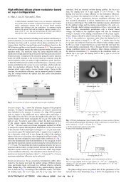
Use a high-power laser to reform <strong>Si</strong> ridges<br />
• A method to fabricate <strong>Si</strong>/<strong>Si</strong>O2 <strong>waveguide</strong>s from bulk silicon using laser<br />
reformation technique is presented.<br />
• The main process is to melt the <strong>Si</strong> ridges into the circular-profile structure<br />
by excimer laser and then oxidize it. This causes a structure with a wider<br />
upper part and a narrower bottom part. After uniformly oxidizing the<br />
structure, <strong>Si</strong> <strong>waveguide</strong>s can be formed on the top.<br />
Cr<br />
Excimer laser illumination<br />
<strong>Si</strong> <strong>waveguide</strong><br />
<strong>Si</strong> substrate<br />
<strong>Si</strong> substrate<br />
<strong>Si</strong> substrate<br />
<strong>Si</strong>O 2 layer<br />
<strong>Si</strong> substrate<br />
Deep RIE etching<br />
Remove the Cr mask<br />
and illuminate excimer<br />
laser<br />
Profile<br />
transformation<br />
High‐temp.<br />
oxidation
Creating a high-aspect-ratio fin<br />
• The geometry of the <strong>Si</strong> ridges before laser illumination is crucial for<br />
the profile transformation.<br />
• low-power reactive-ion-etch ion etch (RIE) using SF6 and CHF3 gases was<br />
applied to create extremely high-anisotropic <strong>Si</strong> ridges.<br />
SF 6<br />
:CHF 3<br />
= 6 : 50 SF 6<br />
: CHF 3<br />
= 7 : 50 SF 6<br />
: CHF 3<br />
= 8 :50 SF 6<br />
: CHF 3<br />
= 8 :50<br />
~50nm
Profile transformation in different widths<br />
160nm<br />
220nm 280nm 380nm<br />
Laser reformation<br />
600nm<br />
Irregular profile transformation
Thermal conduction<br />
The molten depths can be determined dt dby heat ttransfer equation, which hih<br />
includes wavelength, pulse duration, incident angles, and energy densities<br />
as the parameters. Assuming absorbed light is totally converted to heat,<br />
the heat generation rate per unit area (W/cm 2 ) at the illuminated surface is<br />
derived from the Fresnel formulas for the regime of strong absorption as<br />
the following equation.<br />
The calculated molten depth is useful in the<br />
profile transformation analysis and in the<br />
selection of energy densities in laser<br />
reformation.<br />
g<br />
( t<br />
) <br />
r<br />
II<br />
n<br />
n<br />
2<br />
E<br />
( t)<br />
cos<br />
t<br />
<br />
n<br />
d<br />
<br />
r<br />
<br />
n<br />
n<br />
2n1<br />
cosi<br />
cos t<br />
<br />
(<br />
n2<br />
<br />
i<br />
<br />
2<br />
) cos<br />
<br />
1 1<br />
i<br />
2n1<br />
cos<br />
cos<br />
<br />
( n <br />
i<br />
) cos<br />
<br />
2 i<br />
1<br />
n<br />
1<br />
i<br />
2<br />
2<br />
2<br />
......................(1)<br />
t<br />
2<br />
2012/6/27 14
Circular profile after illumination<br />
• A ridge perfectly transformed into a circular-profile structure.<br />
• Surface tension supported and formed this structure during the silicon was<br />
melted.<br />
• The surface of the reformed structure was extremely smooth, which h is<br />
advantageous to the reduction of scattering loss.<br />
1.5um<br />
300nm<br />
Laser illuminationi 600nm
Wavy profile after illumination<br />
• There was wavy morphology after laser<br />
illumination.<br />
• The P-R instability was more severe in the<br />
narrower ridges.<br />
Plateau-Rayleigh Instability<br />
Wavy profile<br />
2012/6/27
Enlarge the size of <strong>Si</strong> ridges<br />
• To avoid P-R instability, we<br />
deliberately enlarge the size of <strong>Si</strong><br />
ridges.<br />
• The ridge with the width of 500nm<br />
transformed into an approximately<br />
circular profile. However, there are<br />
still ups and downs.<br />
• The ridge with the width of 600nm<br />
transformed into an ellipse-like<br />
profile. Nevertheless, the profile is<br />
quite uniform in the light<br />
transmission direction.<br />
520nm<br />
610nm<br />
2.4um<br />
1090nm<br />
560nm<br />
980nm<br />
660nm
Oxidation (1)<br />
• The difference between upper width and bottom width of the reformed<br />
structure determines the diameter of the <strong>waveguide</strong> core after oxidation.<br />
• The finally oxidation process have to be controlled accurately. Twice<br />
oxidations were applied to completely isolate the upper <strong>Si</strong> core.<br />
After laser illumination First oxidation Second oxidation
Oxidation (2)<br />
• The profile would further change after oxidation.<br />
• In this case, the oxidation time is not enough to completely oxidize the<br />
neck of the structure. This may cause serious light leaking into the<br />
substrate.<br />
After laser illumination First oxidation Second oxidation<br />
2012/6/27 19
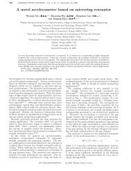
Discussion<br />
• The <strong>Si</strong> <strong>waveguide</strong> core was isolated from the <strong>Si</strong> substrate. The core diameter<br />
is about 400nm. The distance between <strong>Si</strong> <strong>waveguide</strong> and <strong>Si</strong> substrate can be<br />
further increased.<br />
<strong>Si</strong> <strong>waveguide</strong><br />
400nm<br />
400nm<br />
isolated<br />
Not isolated<br />
Oxide layer<br />
2012/6/27 20
The Optical mode is like that of optical fiber<br />
• The structure can be formulated by<br />
applying conventional fiber principle.<br />
• it shows the potential of the coupling loss<br />
reduction with fiber since the cross<br />
section is matched.<br />
300nm<br />
Wavelength: 1550nm<br />
Index of Core (n 1 ): 3.45<br />
Index of Cladding (n 2<br />
): 1.45<br />
Core diameter (a): 300nm<br />
V b k * * (<br />
2 2<br />
)<br />
V-number = k 0<br />
*a*squ(n 12<br />
-n 22<br />
) =<br />
1.9035 < 2.405 => single mode
Design using optical fiber formulation<br />
<strong>Si</strong>ngle mode <strong>waveguide</strong> can be achieved<br />
under the condition of the <strong>Si</strong>/<strong>Si</strong>O 2<br />
<strong>waveguide</strong> with the <strong>Si</strong> core diameter<br />
below 380nm.<br />
V-numb er<br />
3.5<br />
3.0<br />
25 2.5<br />
2.0<br />
1.5<br />
Core diameter<br />
Mode field diameter<br />
mode field diameter (nm)<br />
1.0<br />
150 200 250 300 350 400 450 500 550 600<br />
540<br />
Core diameter (nm)<br />
560<br />
Multi mode<br />
520<br />
500<br />
480<br />
460<br />
440<br />
420<br />
400<br />
380<br />
<strong>Si</strong>ngle mode<br />
360<br />
150 200 250 300 350 400 450 500 550 600<br />
core diameter (nm)
Summary<br />
• An incompatibility for the integration of<br />
optics and electronics on a single chip<br />
occur due to large difference of oxide<br />
layer. Here, a novel method to fabricate<br />
<strong>Si</strong>/<strong>Si</strong>O 2 <strong>waveguide</strong>s from non-SOI<br />
substrate using laser reformation technique<br />
is demonstrated.<br />
• Under proper illuminating condition, the <strong>Si</strong> ridges would be melted and<br />
reshaped to circular-profile structure. An optical fiber-like formulation can be<br />
easily applied to this structure. The process provides a new platform to<br />
design optoelectronic devices on a single chip.