A novel accelerometer based on microring resonator
A novel accelerometer based on microring resonator
A novel accelerometer based on microring resonator

You also want an ePaper? Increase the reach of your titles
YUMPU automatically turns print PDFs into web optimized ePapers that Google loves.
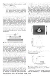
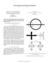
September 10, 2009 / Vol. 7, No. 9 / CHINESE OPTICS LETTERS 799where m e is the equivalent mass index. In other words,with a larger length, a higher sensitivity can be obtainedbut with a lower natural frequency of the structure.Therefore, suitable length is very significant to improvethe vibrati<strong>on</strong> sensitivity within enough working frequencyrange.In the structure depicted in Fig. 1, the couplingcoefficient is a very important parameter, which transfersthe vibrati<strong>on</strong> of the suspended waveguide to the changeof output optical power. C<strong>on</strong>sidering the TE mode of theequivalent slab in x-z plane, the expressi<strong>on</strong> of couplingcoefficient k is given by [13,14]k = K(2s 0 )[∫ ∞[× exp − α )]2−∞ 2R z2 − j(β 1 z − β 2 z + z32R 2β 2 dz, (4)Fig. 1. Structure of a <strong>microring</strong> res<strong>on</strong>ator <str<strong>on</strong>g>accelerometer</str<strong>on</strong>g>. (a)Top view; (b) cross secti<strong>on</strong> at the dotted line in (a).Fig. 2. Maximum deflecti<strong>on</strong> of the suspended waveguide versusbeam length.In a practical situati<strong>on</strong>, it is usually desirable to obtainthe optimal parameters to maximize the sensitivityof the <str<strong>on</strong>g>accelerometer</str<strong>on</strong>g> within a large frequency range. Toanalyze the dynamic resp<strong>on</strong>se of the <str<strong>on</strong>g>accelerometer</str<strong>on</strong>g>, FEMis c<strong>on</strong>ducted to the model <str<strong>on</strong>g>based</str<strong>on</strong>g> <strong>on</strong> different dimensi<strong>on</strong>sand accelerati<strong>on</strong>s. The waveguide width w and thicknessh are selected as 0.5 µm to guarantee the single-modepropagati<strong>on</strong>. Then the length l is determined by analyzingthe deformati<strong>on</strong> of the waveguide under an accelerati<strong>on</strong>of 1g (9.8 m/s 2 ).Figure 2 shows the x-directi<strong>on</strong> deformati<strong>on</strong> of the suspendedwaveguide with the length varying from 100 to1000 µm. It is obvious that the larger length-to-width ratiocan increase the amplitude of the beam vibrati<strong>on</strong>, resultingin relatively high sensitivity. Based <strong>on</strong> the theoryof vibrati<strong>on</strong>al mechanics, the deformati<strong>on</strong> of the waveguidecan be expressed asδ = 4Pl3Ewh 3 , (2)where E is the Young’s modulus of the waveguide andP is an external inertial force induced by accelerati<strong>on</strong>.However, the natural frequency of the <str<strong>on</strong>g>accelerometer</str<strong>on</strong>g> isdefined as√Ewhω n =34l 3 , (3)m ewhere K (2s 0 ) is the coupling coefficient for two parallelwaveguides which are separated by a distance2s 0 = d + w; β 1 and β 2 are the x-z comp<strong>on</strong>ents ofpropagati<strong>on</strong> c<strong>on</strong>stants inside the straight and <strong>microring</strong>waveguides, respectively; the transverse decay c<strong>on</strong>stantα 2 is given by α 2 = √ β2 2 − n2 0 k2 0 , where n 0 and k 0 arethe substrate refractive index and the free-space wavevector, respectively. By use of this equati<strong>on</strong>, we are ableto analyze the physical parameters affecting the couplingcoefficient: <strong>microring</strong> radius, refractive index, and gapspacing.Figures 3 and 4 show the dependences of couplingcoefficient <strong>on</strong> the ring radius and refractive index, respectively.Firstly, at given gap spacing and refractiveindex, the coupling coefficient increases with the ringradius increasing because of the increased effective couplinglength. Sec<strong>on</strong>dly, at fixed ring radius and gapspacing, the coupling coefficient decreases when the refractiveindex increases, resulting in the str<strong>on</strong>g c<strong>on</strong>finedoptical field.Fig. 3. Coupling coefficient as a functi<strong>on</strong> of ring radius.Gap spacing d=0.1 µm, refractive indices of waveguidesn 1=n 2=2.0.Fig. 4. Coupling coefficient as a functi<strong>on</strong> of refractive indexof waveguides. Ring radius R=50 µm, d=0.1 µm.
800 CHINESE OPTICS LETTERS / Vol. 7, No. 9 / September 10, 2009Fig. 5. Coupling coefficient as a functi<strong>on</strong> of gap spacing.R=50 µm, n 1=n 2=2.0.Fig. 6. Accelerati<strong>on</strong> versus coupling coefficient. R=50 µm,width w=0.5 µm, n 1=n 2=2.0.Fig. 7. Change of x-deformati<strong>on</strong> with accelerati<strong>on</strong>.Fig. 8. Coupling coefficient versus vibrati<strong>on</strong> frequency. Accelerati<strong>on</strong>a=0.1g.Therefore, we c<strong>on</strong>sider a 50-µm-diameter <strong>microring</strong>coupled to a straight waveguide, both with the refractiveindex of 2.0. Next we focus <strong>on</strong> the gap spacing betweentwo waveguides.Figure 5 shows that the coupling coefficient decreasesby almost 64% with the gap increasing from 0.05 to 0.25µm. We choose 0.1 µm as the initial gap spacing betweenthe two waveguides to ensure enough optical power coupledinto the <strong>microring</strong>.Under the c<strong>on</strong>diti<strong>on</strong> of accelerati<strong>on</strong> a from 0 to 5g al<strong>on</strong>gnegative x-axis, the coupling coefficient varies with theaccelerati<strong>on</strong>, as shown in Fig. 6. The sensitivity of the<str<strong>on</strong>g>accelerometer</str<strong>on</strong>g>, s, can be calculated via S = ∆pa, which isdecided by the input optical power and power change ∆pat the output of the straight waveguide.The suspended waveguide is a c<strong>on</strong>tinuous system. Underthe harm<strong>on</strong>ic vibrati<strong>on</strong>, every element of the suspendedwaveguide suffers different deformati<strong>on</strong>. Figure7 describes the x-deformati<strong>on</strong> of the middle part at thesuspended waveguide. The lines in the figure present thedeformati<strong>on</strong>s of the points 1−4 bel<strong>on</strong>ging to the waveguide(see Fig. 1), respectively. It is obvious that the deformati<strong>on</strong>sare almost uniform within the 50-µm range.That is to say, the x-deformati<strong>on</strong>s of the straight waveguidecan be taken as the same in the coupling regi<strong>on</strong>, becausethe differences of x-deformati<strong>on</strong> am<strong>on</strong>g the pointsare very small compared with the x-deformati<strong>on</strong> value.Moreover, the z-deformati<strong>on</strong> is almost less than 0.001%of the x-deformati<strong>on</strong>. Therefore, the cross-axis sensitivitycan be ignored.Frequency resp<strong>on</strong>se is an important performance of an<str<strong>on</strong>g>accelerometer</str<strong>on</strong>g>. If the frequency of the external accelerati<strong>on</strong>is the same with the natural frequency of the structure,the <str<strong>on</strong>g>accelerometer</str<strong>on</strong>g> will be destroyed as a result ofres<strong>on</strong>ance. Therefore, the maximum working frequencyshould be lower than the first natural frequency, which isgiven by√ω 1 = 9 Eh 24 π2 12ρl4, (5)where ρ is described as mass density. We can get the firstnatural frequency of 4605 Hz via numerical calculati<strong>on</strong>.As the accelerati<strong>on</strong> frequency increases from 0 Hz to thefirst natural frequency, the deformati<strong>on</strong> of the suspendedwaveguide decreases, resulting in the change of couplingcoefficient. An ideal <str<strong>on</strong>g>accelerometer</str<strong>on</strong>g> is expected to have aflat frequency resp<strong>on</strong>se and allow undistorted measurementof the accelerati<strong>on</strong> at all frequencies. Figure 8shows that the coupling coefficient varies with the accelerati<strong>on</strong>frequency for a=0.1g. The calculated couplingcoefficient obtained through Eqs. (1) and (4) changes by<strong>on</strong>ly 0.013% in the range of 0−500 Hz. Therefore, it canbe approximately c<strong>on</strong>sidered as a c<strong>on</strong>stant.In c<strong>on</strong>clusi<strong>on</strong>, we present the design and analysis ofa <str<strong>on</strong>g>novel</str<strong>on</strong>g> <str<strong>on</strong>g>accelerometer</str<strong>on</strong>g> <str<strong>on</strong>g>based</str<strong>on</strong>g> <strong>on</strong> the <strong>microring</strong> res<strong>on</strong>ator.The coupling coefficient related to the accelerati<strong>on</strong> is analyzedas a functi<strong>on</strong> of the gap spacing between the twowaveguides. The structural parameters, such as ring radius,refractive index, and initial gap spacing, are optimizedto get better coupling coefficient. The simulati<strong>on</strong>results show that the mechanical sensitivity is 0.015µm/g and cross-axis sensitivity is less than 0.001%. Thecoupling coefficient changes <strong>on</strong>ly 0.013% below 500 Hz,which is well above the working frequency for seismicprospecting applicati<strong>on</strong>s.This work was partially supported by the Nati<strong>on</strong>alNatural Science Foundati<strong>on</strong> of China under Grant No.60578048.References1. A. Mita and I. Yokoi, Proc. SPIE 4330, 479 (2001).
September 10, 2009 / Vol. 7, No. 9 / CHINESE OPTICS LETTERS 8012. W. Zhang, L. Liu, F. Li, and Y. Liu, Chin. Opt. Lett.5, 507 (2007).3. H. Y. Au, S. K. Khijwania, and H. Y. Tam, Proc. SPIE7004, 70042S (2008).4. B. Wu, C. Chen, G. Ding, D. Zhang, and Y. Cui, Opt.Eng. 43, 313 (2004).5. W. Zhang, Y. Liu, and F. Li, Chin. Opt. Lett. 6, 631(2008).6. J. Nayak, T. Srinivas, A. Selvarajan, and D. V. K. Sastry,J. Microlith. Microfab. Microsyst. 5, 043012 (2006).7. E. Ollier, P. Philippe, C. Chabrol, and P. Mottier, J.Lightwave Technol. 17, 26 (1999).8. K. E. Speller and D. Yu 5417, 63 (2004).9. C.-Y. Chao and L. J. Guo, J. Lightwave Technol. 24,1395 (2006).10. Z. Xia, Y. Chen, and Z. Zhou, IEEE J. Quantum Electr<strong>on</strong>.44, 100 (2008).11. Y. Zhang, (ed.) Theory and Data Soluti<strong>on</strong>s in Reflecti<strong>on</strong>Seismic Explorati<strong>on</strong> (in Chinese) (Geological PublishingHouse, Beijing, 2007).12. S. C. Hagness, D. Rafizadeh, S. T. Ho, and A. Taflove,J. Lightwave Technol. 15, 2154 (1997).13. Y. Liu, T. Chang, and A. E. Craig, Opt. Eng. 44,084601 (2005).14. K. Okamoto, Fundamentals of Optical Waveguides (AcademicPress, San Diego, 2000).