Application of MCHE in Commercial Air Conditioners
Application of MCHE in Commercial Air Conditioners
Application of MCHE in Commercial Air Conditioners

You also want an ePaper? Increase the reach of your titles
YUMPU automatically turns print PDFs into web optimized ePapers that Google loves.
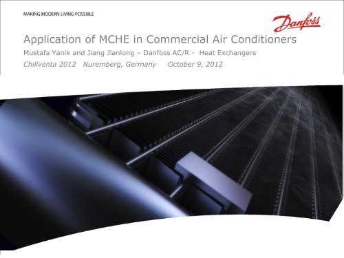
<strong>Application</strong> <strong>of</strong> <strong>MCHE</strong> <strong>in</strong> <strong>Commercial</strong> <strong>Air</strong> <strong>Conditioners</strong><br />
Mustafa Yanik and Jiang Jianlong – Danfoss AC/R - Heat Exchangers<br />
Chillventa 2012 Nuremberg, Germany October 9, 2012<br />
Refrigeration and A/C Controls Division Date | 1
Outl<strong>in</strong>e<br />
• Brief Intro to <strong>MCHE</strong><br />
• <strong>MCHE</strong> Condenser vs Evaporators – Drivers/Challanges<br />
• Implementation <strong>of</strong> <strong>MCHE</strong> Evaporators <strong>in</strong> <strong>Commercial</strong> AC<br />
• Basic Features <strong>of</strong> <strong>MCHE</strong> Evaporator for AC<br />
• Refrigerant Distribution vs Performance<br />
• <strong>Air</strong> Flow Distribution vs Performance<br />
• Two Row <strong>MCHE</strong> Coils <strong>in</strong> Reversible Systems<br />
• Multi Circuit Coils – Row Split<br />
• Comparison <strong>of</strong> <strong>MCHE</strong> w/ FT <strong>in</strong> a 20kW System<br />
Refrigeration and A/C Controls Division March 15, 2012 | 2
Brief Intro to <strong>MCHE</strong><br />
5<br />
4<br />
3<br />
1. Baffle – for multi pass<br />
2. Microchannel tube<br />
3. Header<br />
4. End cap<br />
5. Side plate – for protection<br />
2<br />
6. Enhanced f<strong>in</strong>s with louvers<br />
1<br />
6<br />
1<br />
7<br />
• All Alum<strong>in</strong>um Construction<br />
• Furnace Brazed<br />
Refrigeration and A/C Controls Division March 15, 2012 | 3
<strong>MCHE</strong> Condensers vs Evaporators<br />
Condenser Evaporator<br />
Charge Reduction 70% 25%<br />
Size Reduction 66% 66%<br />
Weight Reduction 70% 70%<br />
Corrosion Resistance Galvanic Formicary<br />
Low Raw Material<br />
Cost<br />
√<br />
√<br />
High Performance at<br />
Affordable Cost<br />
√<br />
√<br />
Reduced <strong>Air</strong> Side<br />
Pressure Drop<br />
Drivers<br />
√<br />
√<br />
Refrigerant<br />
Distribution<br />
Impact <strong>of</strong> <strong>Air</strong> Mal-<br />
Distribution<br />
Intermediate<br />
Headers<br />
Water Condensate<br />
Challenges<br />
Condenser<br />
Non Issue<br />
Negligible<br />
Ok<br />
Not Applicable<br />
Evaporator<br />
Distributor Design<br />
Critical<br />
Critical<br />
Not Acceptable<br />
Vertical<br />
Orientation - F<strong>in</strong><br />
Design Critical<br />
Frost Accumulation Not Applicable Challeng<strong>in</strong>g<br />
Refrigeration and A/C Controls Division March 15, 2012 | 4
Basic Construction <strong>of</strong> <strong>MCHE</strong> Evaporators<br />
• Slab Coil<br />
• Two Row – Folded/Formed<br />
• A Coil – Folded/Formed<br />
Refrigeration and A/C Controls Division March 15, 2012 | 5
<strong>MCHE</strong> Refrigerant Distributor Design<br />
• General Description : Distributor Tube with<strong>in</strong> the header with orifices<br />
• Critical Features:<br />
• Flow Pattern <strong>in</strong> Distributor Tube<br />
• Size <strong>of</strong> the distributor tube<br />
• Spray Pattern<br />
• Location <strong>of</strong> distributor tube<br />
• Spac<strong>in</strong>g <strong>of</strong> orifice holes<br />
• Angular location <strong>of</strong> the orifice holes<br />
• Diameter <strong>of</strong> orifice holes<br />
• Pressure Drop Equalization<br />
• Multiple Outlet Connection<br />
• Secondary Outlet Manifold<br />
• Size <strong>of</strong> Outlet Manifold<br />
• Dual Inlet Connections<br />
Refrigeration and A/C Controls Division March 15, 2012 | 6
Simulation to calculate Sensitivity <strong>of</strong> <strong>MCHE</strong> Evaporator to<br />
Refrigerant Distribution<br />
• Method<br />
• Divide a <strong>MCHE</strong> coil <strong>in</strong>to 2 sections<br />
• Prescribe vary<strong>in</strong>g refrigerant flow to each section<br />
• Coil Description<br />
• Size : 1000 mm by 1000mm and 25mm deep<br />
• 23 FPI f<strong>in</strong> density<br />
• MPE: 26 channels – 0.635mm by 0.74mm<br />
• Thermal Conditions<br />
• Refrigerant – R410A<br />
• <strong>Air</strong> Temperature: 80/67 DB/WB<br />
• <strong>Air</strong> Velocity = 500 ft/m<strong>in</strong> (2.54 m/s)<br />
• Tliq = 100F<br />
• Tsat_evap = 52F (10.6 C)<br />
1 2<br />
Refrigeration and A/C Controls Division March 15, 2012 | 7
Q / Q_uniform<br />
Effect <strong>of</strong> Refrigerant Flow Mal-distribution on <strong>MCHE</strong> Coil Capacity at<br />
Various SH<br />
100%<br />
95%<br />
90%<br />
85%<br />
80%<br />
75%<br />
SH = 13F (7.2C)<br />
SH = 10F (5.6C)<br />
SH = 7F (3.9C)<br />
SH = 4F (2.2C)<br />
70%<br />
65%<br />
60%<br />
50%/50% 45%/55% 40%/60% 35%/65% 30%/70%<br />
mfr_left / mfr_right<br />
Refrigeration and A/C Controls Division March 15, 2012 | 8
Q / Q_uniform<br />
Effect <strong>of</strong> Refrigerant Phase Mal-distribution on <strong>MCHE</strong> Coil Capacity<br />
at Various SH<br />
100%<br />
95%<br />
90%<br />
85%<br />
80%<br />
75%<br />
SH = 13F (7.2C)<br />
SH = 10F (5.6C)<br />
SH = 7F (3.9C)<br />
SH = 4F (2.2C)<br />
70%<br />
65%<br />
60%<br />
20%/20% 25%/15% 30%/10% 35%/5%<br />
x_left / x_right<br />
Refrigeration and A/C Controls Division March 15, 2012 | 9
Simulation to calculate Sensitivity <strong>of</strong> <strong>MCHE</strong> Evaporator to <strong>Air</strong> Flow<br />
Mal-distribution<br />
• Method<br />
• Divide a <strong>MCHE</strong> coil <strong>in</strong>to 2 sections (left to right and top to bottom)<br />
• Assume air flow does not effect refrigerant flow<br />
• Prescribe vary<strong>in</strong>g air flow to each section<br />
2<br />
1<br />
1 2<br />
Refrigeration and A/C Controls Division March 15, 2012 | 10
Q / Q_uniform<br />
Effect <strong>of</strong> <strong>Air</strong> Mal-distribution (Left to Right & Top to Bottom) on<br />
<strong>MCHE</strong> Coil Capacity at 10F SH<br />
100%<br />
95%<br />
90%<br />
85%<br />
80%<br />
75%<br />
<strong>Air</strong> Mal Distribution Left to Right<br />
<strong>Air</strong> Mal Distribution Top to Bottom<br />
70%<br />
65%<br />
60%<br />
50%/50% 60%/40% 70%/30% 80%/20%<br />
mfr_air_1 / mfr_air_2<br />
Refrigeration and A/C Controls Division March 15, 2012 | 11
Circuit Orientation and air mal-distribution <strong>in</strong> <strong>MCHE</strong><br />
Evap Coils<br />
Refrigeration and A/C Controls Division March 15, 2012 | 12
Circuit Orientation and air mal-distribution <strong>in</strong> FT Evap<br />
Coils<br />
What is ok for <strong>MCHE</strong> is not ok for FT and vice versa.<br />
Refrigeration and A/C Controls Division March 15, 2012 | 13
<strong>Air</strong> Mal Distribution <strong>in</strong> Condensers – Self Correct<strong>in</strong>g<br />
Refrigeration and A/C Controls Division March 15, 2012 | 14
<strong>Air</strong> Mal Distribution <strong>in</strong> Evaporators – Self Destruct<strong>in</strong>g<br />
Refrigeration and A/C Controls Division March 15, 2012 | 15
Two row <strong>MCHE</strong> Coils <strong>in</strong> Reversible Systems<br />
• Two critical features<br />
• Folded/formed coils without <strong>in</strong>termediate headers<br />
• Elim<strong>in</strong>ate refrigerant mal-distribution<br />
• Counter-flow <strong>in</strong> Condenser mode, hence parallel flow <strong>in</strong> evaporator mode<br />
• Ensure condenser sub-cool<strong>in</strong>g<br />
• About 10% <strong>in</strong>crease <strong>in</strong> HP Capacity w/ 4% drop <strong>in</strong> Cool<strong>in</strong>g Capacity based<br />
on test data<br />
Refrigeration and A/C Controls Division March 15, 2012 | 16
<strong>MCHE</strong> Evaporators for Multi Circuit Systems<br />
• Interlaced Circuit<strong>in</strong>g not<br />
available<br />
• Face Split Configuration<br />
• Side by Side Split is preferred<br />
• Easier to Distribute Refrigerant<br />
• Higher refrigerant velocity and<br />
performance<br />
• Smaller headers – lower cost<br />
• Row Split<br />
• Thermodynamic advantage for<br />
upstream system<br />
• Lower capacity <strong>in</strong> the downstream<br />
system preferred<br />
Circuit 1 Circuit 2<br />
Circuit 1 Circuit 2<br />
Refrigeration and A/C Controls Division March 15, 2012 | 17
Comparison <strong>of</strong> FT Coil w/ <strong>MCHE</strong> <strong>in</strong> a 20 KW <strong>Commercial</strong> AC<br />
• FT Coil Description<br />
• 8mm OD <strong>in</strong>ternally enhanced Cu<br />
tub<strong>in</strong>g<br />
• 1 <strong>in</strong>ch vertical spac<strong>in</strong>g<br />
• 0.866 <strong>in</strong>ch horizontal spac<strong>in</strong>g<br />
• Enhanced F<strong>in</strong>s with Louvers<br />
• 4rows<br />
• Face Area 9 sqft<br />
• <strong>MCHE</strong> Description<br />
• 16mm MPE tub<strong>in</strong>g<br />
• 16 ports – 0.63mm by 0.74mm<br />
• Folded 2 row<br />
• 16 f<strong>in</strong>/<strong>in</strong>ch<br />
• Two <strong>in</strong>lets / Two outlets<br />
• Face Area 9 sqft<br />
Refrigeration and A/C Controls Division March 15, 2012 | 18
Comparison <strong>of</strong> FT Coil w/ <strong>MCHE</strong> <strong>in</strong> a 20 KW <strong>Commercial</strong> AC<br />
• Coil Weight Reduced by 66%<br />
• Coil Depth Reduced by 50%<br />
• Refrigerant Charge Reduced by 18%<br />
Refrigeration and A/C Controls Division March 15, 2012 | 19
Questions?<br />
Refrigeration and A/C Controls Division March 15, 2012 | 20