SmaFinger - RFID Webshop
SmaFinger - RFID Webshop
SmaFinger - RFID Webshop

Create successful ePaper yourself
Turn your PDF publications into a flip-book with our unique Google optimized e-Paper software.
TAGnology <strong>RFID</strong> GmbH | Grazer Vorstadt 142 | 8570 Voitsberg | AUSTRIA<br />
phone: +43 (0)3142/28 9 28-10 | fax: +43 (0)3142/28 9 28-20 | office@tagnology.com | www.tagnology.com<br />
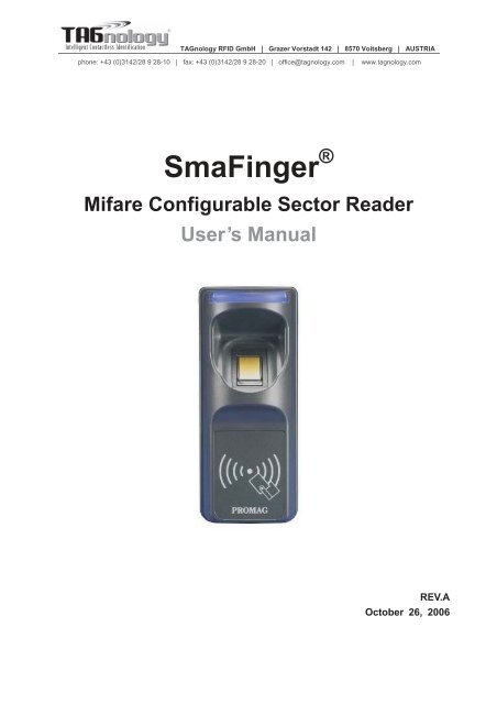
<strong>SmaFinger</strong> ®<br />
Mifare Configurable Sector Reader<br />
User’s Manual<br />
REV.A<br />
October 26, 2006
PROMAG<br />
<strong>SmaFinger</strong><br />
REV.A<br />
<strong>SmaFinger</strong> is a fingerprint reader developed on the so-call contactless smart card 13.56 Mhz <strong>RFID</strong> technology. The<br />
integration of biometric technology by fingerprint identification and 13.56Mhz <strong>RFID</strong> technology make Smafinger be<br />
capable of biometric and contactless performance without spending large amount of expenses in running system<br />
upgrading with fingerprint system extension. On the aspect of personal privacy issue, <strong>SmaFinger</strong> supply the high secure<br />
of protection on privacy concern due to every fingerprint is stored on a card. Also the reader itself supports Mifare<br />
MAD1/MAD2 format make user end be able to issue their customized ID cards.<br />
Features:<br />
1. Support MAD1/MAD2 standard, and support customer MAD-AID setting.<br />
2. Support Non-MAD format with user-defined sector number.<br />
3. Support Anti-Collision (Two cards together can be read at the same time).<br />
4. Support used card with data offset and length.<br />
5. Support Multi Sectors.<br />
6. Support Mifare ® Standard 4K or Mifare ® Standard 1K card.<br />
7. Each Reader with Reader ID for multi-link application.<br />
8. Output interface: Wiegand (Default), ABA-TK2 and RS232.<br />
9. Wiegand output selectable from 26 bits to 128 bits.<br />
10. RS232 output packet can be set with Header, Reader ID and Trailer.<br />
Application:<br />
1. Access Control.<br />
2. Time Attendance.<br />
3. Guest Registration System.<br />
4. Academic Services.<br />
5. Info Services.<br />
2
PROMAG<br />
<strong>SmaFinger</strong><br />
REV.A<br />
Mifare ® Application Directory (MAD) Support:<br />
<strong>SmaFinger</strong> support the MAD format card, the MAD (mifare® application directory) standard proposes the<br />
introduction of common data structures for card application directory entries. <strong>SmaFinger</strong> reader should take<br />
advantage of this feature using those sector pointers instead of physical sector number.<br />
Auto Mode<br />
Request<br />
Anticollision<br />
Card On Reader<br />
Is MAD<br />
Card<br />
Ye s<br />
No Tag<br />
No<br />
The <strong>SmaFinger</strong> will search the AID from mifare®<br />
application directory (MAD) , then got a correct sector<br />
number from MAD. If the card is not a MAD card, the<br />
<strong>SmaFinger</strong> will use the Non-MAD Sector# (Setting by<br />
<strong>SmaFinger</strong> Utility).<br />
About MAD please see the web pages:<br />
http://www.mifare.net<br />
http://www.semiconductors.philips.com/acrobat/other/id<br />
entification/M001824.pdf<br />
AID Match<br />
No<br />
Ye s<br />
Get<br />
Using MF700<br />
Application Sector#<br />
Non-MAD Sector#<br />
PASS<br />
APP KEY<br />
Authenticate<br />
NG<br />
Read Sector Data<br />
Un-know<br />
Output Data<br />
3
PROMAG<br />
<strong>SmaFinger</strong><br />
REV.A<br />
User-Data Format<br />
<strong>SmaFinger</strong> will send out the data following the format as below, the user data length defined by the Data-Info.<br />
At wiegand output format, the data output length is fixed (defined by Number Of Bits), so the user data would<br />
be cut if longer than Number of Bits, or the user data would be appended with zero "0" if shorter than Number<br />
of Bits.<br />
Byte 0 Byte 15<br />
Block 0 Data-Info<br />
Application<br />
Sector #<br />
Block 1<br />
Block 2<br />
Block 3<br />
USER DATA (Max 128 Bytes)<br />
Data-Info<br />
bit7 bit6 bit5 bit0<br />
Data Type (11b)<br />
Data Length<br />
Data Type is fixed with 11b which meets "any other data" type of "Card Holder information" as MAD standard.<br />
And data length is including the data with ending zero "0", so the number of data byte sent by <strong>SmaFinger</strong> is<br />
equal to data length with one less for RS232 output.<br />
Example: Data Length is 16, <strong>SmaFinger</strong> only send out 15 bytes for RS232 output.<br />
4
PROMAG<br />
<strong>SmaFinger</strong><br />
REV.A<br />
Wires Assignment<br />
Color Symbol I/O Description<br />
Red VCC IN Power Input : DC 7.5V~12V<br />
Black GND IN Power Ground<br />
White DATA 1 OUT Wiegand Data 1 Signal / ABA TK2 Clock (Strobe)<br />
Green DATA 0 OUT Wiegand Data 0 Signal / ABA TK2 Data<br />
Yellow TXD OUT RS232 TXD (To Host RXD)<br />
Blue RXD IN RS232 RXD (To Host TXD)<br />
Orange CP OUT ABA TK2 Card Present (for <strong>SmaFinger</strong> REV.D and later)<br />
Brown LED/BUZEER IN External LED/BUZZER Control<br />
Connect To Reader Kit before configure the <strong>SmaFinger</strong> Reader.<br />
To configure the <strong>SmaFinger</strong> reader you need connect the reader to the Reader-Kit first as below:<br />
ORANGE<br />
Reader-KIT<br />
BLACK<br />
WHITE<br />
RED<br />
YELLOW<br />
BLUE<br />
GREEN<br />
BROWN<br />
CP<br />
GND<br />
D1<br />
D0<br />
RX<br />
TX<br />
VCC<br />
" "<br />
" "<br />
WAS-T0029<br />
The above housing is for reference only<br />
9VDC<br />
Note:<br />
Reader-Kit is a test connection kit for <strong>SmaFinger</strong> configuration use. It is an optional item for purchasing.<br />
5
PROMAG<br />
<strong>SmaFinger</strong><br />
REV.A<br />
Mifare Reader Utility<br />
1. Mifare Settings:<br />
MAD-AID: (Default=4703)<br />
MAD Application Identifier number is authorized and assigned by Mifare.net upon the customer’s request<br />
for registered Application Identifier in a mifare® application open system (AID: 0000h~FFFFh).<br />
Or it is also possible for the user to define the AID himself for the application in user defined closed<br />
system without registering into MAD group. According to the AID, <strong>SmaFinger</strong> can find and read the<br />
corresponding sector on the MAD card.<br />
Non-MAD Sector: (Default =0)<br />
When the card is Non-MAD format, <strong>SmaFinger</strong> will only read the "Non-MAD Sector".<br />
(1K Card Sector: 0~15, 4K Card Sector:0~39). For the Non-MAD application, user can freely define the<br />
Sector.<br />
App Key (KEY_A): (Default=FFFFFFFFFFFF)<br />
App Key must be the same as the KEY_A of the card issued. This means <strong>SmaFinger</strong> only can read the<br />
sector data on the card with the same KEY_A.<br />
Encrypt: (Default=None)<br />
Fraud prevention, Select Encrypt Mode (None, Encrypt 1, Encrypt 2, Encrypt 3, Encrypt 4, Encrypt 5) to<br />
protected your card data. (Remark: Encrypt mode must to work together with the same encrypt mode of<br />
"Mifare Card Issuer" software.)<br />
6
PROMAG<br />
<strong>SmaFinger</strong><br />
REV.A<br />
Used Card (Not issued by "Mifare Card Issuer")<br />
You have to indicate the data position in the card, when the card is not issued by "Mifare Card Issuer"<br />
software. And you must set the "Offset" (Max 255, and base from zero) form the beginning of sector and<br />
set your data "Length" (Max 128).<br />
Example:<br />
If your card data in the grey grid of sector, you have to set the "Offset" = 17, and set the "Length"= 20.<br />
AID Sector (or Non-MAD Sector)<br />
Block 0 0 1 2 3 4 5 6 7 8 9 10 11 12 13 14 15<br />
Block 1 16 17 18 19 20 21 22 23 24 25 26 27 28 29 30 31<br />
Block 2 32 33 34 35 36 37 38 39 40 41 42 43 44 45 46 47<br />
7
PROMAG<br />
<strong>SmaFinger</strong><br />
REV.A<br />
2. Reader Settings<br />
Reader ID : (Default=0)<br />
<strong>SmaFinger</strong> Reader ID for multi link application. (ID: 0~99).<br />
Interface : (Default=Wiegand)<br />
<strong>SmaFinger</strong> can be set as Wiegand , RS232 or ABA-TK2 output.<br />
Read Mode: (Default=Card Data Only)<br />
a. Card Data Only: Read card sector data only; If any error (ex. mifare key error), reader will show "Card<br />
Invalid" status.<br />
b. Card Data or CSN (Card Serial Number): Read card sector data, If any error (ex. mifare key error),<br />
reader will send the CSN to host.<br />
c. CSN Only: CSN read only.<br />
Output Mode: (Default=Once)<br />
a. Once: Send data (or CSN) to host once.<br />
b. Continue: Keeping sending data (or CSN) to host till card remove.<br />
8
PROMAG<br />
<strong>SmaFinger</strong><br />
REV.A<br />
3. LED / Buzzer Settings<br />
New <strong>SmaFinger</strong> support the LED/Alarm Configuration. Setting the LED/Buzzer to indicate the system<br />
status for end-user.<br />
Enable RS232 Command Set Control: (For 19200,n,8,1 Only)<br />
RS232 LED/Buzzer command set frame as below:<br />
STX J NUMBER (0~9) CR<br />
02h 4Ah 30h~39h 0Dh<br />
Command Table:<br />
NUMBER<br />
Descriptions<br />
0 (30h) All LED Off, Buzzer Off<br />
1 (31h) Green LED ON<br />
2 (32h) Green LED OFF<br />
3 (33h) Red LED ON<br />
4 (34h) Red LED OFF<br />
5 (35h) Buzzer Beep 1 Time<br />
6 (36h) Buzzer Beep 3 Time<br />
7 (37h) Green LED ON with Beep 1 Time<br />
8 (38h) Red LED ON with Beep 3 Time<br />
9 (39h) All LED ON (Orange)<br />
Remark: If Enable the RS232 Command Set Control (for LED/Buzzer), the external LED/Buzzer<br />
control with high/low level control will be disable.<br />
Read Idle: Show LED color after power on or idle state.<br />
Brown wire = PULSE (or Card is valid): Show LED color and beeps to indicate the end-user when<br />
brown wire = PULSE, or card was passed by <strong>SmaFinger</strong> reader.<br />
9
PROMAG<br />
<strong>SmaFinger</strong><br />
REV.A<br />
Brown wire = Inactive ( or Card Is invalid): Show LED color and beeps to indicate the end-user when<br />
brown wire = Inactive, or card was failed by <strong>SmaFinger</strong> reader.<br />
Brown wire = Active: Show LED color and beeps to indicate the end-user that brown wire = Active signal<br />
from Host.<br />
Brown wire Active level: Set Brown wire Active level condition with Host status.<br />
Disable: Always disable the Brown wire. (Default), LED/Buzzer control by reader self.<br />
High: Active High / Normal keep in Low.<br />
Low: Active Low / Normal keep in High.<br />
Remark:<br />
If set Active Low, you may have to connect brown wire to a pull-up resistor (1K~10K) with 5VDC).<br />
Control Brown wire:<br />
After Data Output: The brown wire will be enabling after finished output the card data or CSN. (Default)<br />
Any Time: The brown wire enabled in any time.<br />
Note: See Annex E, the LED/Buzzer also can be controlled externally with High/Low<br />
level control.<br />
10
PROMAG<br />
<strong>SmaFinger</strong><br />
REV.A<br />
4. Wiegand Setting:<br />
Number of Bit s is to set the Wiegand output type you want to meet your Host (or Terminal). It can be 26<br />
to 128 (Default=26).<br />
Include Reader ID 1 is to set the Wiegand output data to include Reader ID when it is enabled.<br />
(Default=Disable).<br />
Bit Sequence is to set the Wiegand output data sequence, it can be standard data sequence (MSB first)<br />
or Reverse data sequence (LSB first). (Default=Standard).<br />
11
PROMAG<br />
<strong>SmaFinger</strong><br />
REV.A<br />
5. ABA-TK2 Settings<br />
Number Of Digital: Set number of digital codes for TK2 output. (Default=10)<br />
Add Reader ID: Add Reader ID into TK2 data. (Default=Disable)<br />
Sequence: Set the TK2 data sequence. (Default=MSB First)<br />
Data Conversion: Select card data format to convert ,<br />
a. BIN to DEC (Default, card issue by Mifare Card Issuer Utility)<br />
b. Decimal String (ex. "123456")<br />
c. BCD<br />
d. Direct (Memory Map)<br />
12
PROMAG<br />
<strong>SmaFinger</strong><br />
REV.A<br />
6. RS232 Setting:<br />
Baudrate can be set 2400bps~57600bps (Default=19200bps)<br />
Data Sequence can be set "LSB" first (Default) and "MSB" first.<br />
Package 2 is to set the output data packet to include Header, Reader ID, Data Length, CR, LF and Trailer.<br />
(Header:00h~FFh, Trailer : 00h~FFh). (Default = None included)<br />
Output Format can be "Binary" or "Hex String" for output format.<br />
Note:<br />
(1).Wiegand output data packet with Reader ID:<br />
Standard Parity( Even)<br />
Reader ID (MSB) Data Bits (LSB) Parity( Odd)<br />
Reverse Parity( Odd)<br />
Reader ID (LSB) Data Bits (MSB) Parity( Even)<br />
(2).RS232 output data packet with Header, Reader ID and Trailer:<br />
Header Reader ID (LSB) Data Bytes (MSB) Trailer<br />
(3).ABA-TK2 with Reader ID:<br />
MSB First SS Reader ID (MSB) Digital Code (LSB) ES LRC<br />
LSB First SS Reader ID (LSB) Digital Code (MSB) ES LRC<br />
Remark:<br />
<strong>SmaFinger</strong> all configuration items are write only, so any users can not read the configuration items from<br />
<strong>SmaFinger</strong> to get the App Key, that is very important to protect your App Key and all configuration items.<br />
13
PROMAG<br />
<strong>SmaFinger</strong><br />
REV.A<br />
Test <strong>SmaFinger</strong> Reader after configuration<br />
After <strong>SmaFinger</strong> configuration is completed you may use Mifare Reader Utility "Test" function to test the<br />
<strong>SmaFinger</strong> to see if the configuration is done correctly.<br />
1. After the configuration on the Mifare Reader Utility software is made, you should click [Update Reader] to<br />
download the current configuration to the <strong>SmaFinger</strong> Reader.<br />
2. After <strong>SmaFinger</strong> configuration is completed, you may click [Test] to test <strong>SmaFinger</strong> Reader.<br />
3. Get an issued mifare ® card to put on <strong>SmaFinger</strong> reader to be read and see the output data on the window<br />
of "<strong>SmaFinger</strong> Output Test".<br />
Wiegand 34 bits output data with standard bit sequence, example as below: (If "Bit Sequence" is standard,<br />
Reverse will detect a wrong with parity error.)<br />
Remark:<br />
1. Using Reader-Kit to test Wiegand (or TK2) signal, this test may be failed if the processor of computer is<br />
too slow.<br />
2. Using Reader-Kit to test Wiegand (or TK2) signal, you have to connect to the physical Comm. Port.<br />
14
PROMAG<br />
<strong>SmaFinger</strong><br />
REV.A<br />
ANNEX A. Hardware Specification<br />
<strong>SmaFinger</strong><br />
Major Feature Mifare ® Application Directory Reader<br />
Access Control & Security<br />
Card Type ISO14443A, Mifare Class 1<br />
(Mifare ® 1K, Mifare ® 4K for MAD1/MAD2)<br />
RF Frequence 13.56MHz<br />
RF Distance 2 50mm (Using the MFA01 Mifare ® card of GIGA-TMS INC.)<br />
DC Power 7.5VDC~12VDC (Max 200mA @ 12V)<br />
Interface<br />
Wiegand 26~128 bits (Standard / Reverse)<br />
RS232 2400bps~57600bps<br />
ABA-TK2 40IPS<br />
Power Input DC 7.5~12V<br />
Power Consume 200mA @ 12V<br />
Operating Temp. 0~50 degree C<br />
Humidity<br />
10~90% Humidity<br />
Dimension<br />
H13.00mm x W54.00mm x D43.00mm<br />
Note:<br />
1. Mifare Class: Mifare Standard 1K/4K.<br />
2. <strong>SmaFinger</strong> RF distance can reach up to 50mm with MFA01 (Mifare ® Standard 1K Card)<br />
of GIGA-TMS INC.<br />
15
PROMAG<br />
<strong>SmaFinger</strong><br />
REV.A<br />
ANNEX B. Wiegand Interface<br />
The Data 1 and Data 0 signals are held at a logic high level unit, the reader is ready to send a data stream.<br />
The reader places data as asynchronous low-going pulses on the Data 1 or Data 0 lines to transmit the data<br />
stream to Host. The Data 1 and Data 0 pulses will allowable pulse width times and pulse interval times for the<br />
<strong>SmaFinger</strong> reader.<br />
Data 1 Signal<br />
Data 0 Signal<br />
` Tpw Tpi Tpw Tpi<br />
Pulse Times<br />
Symbol Description Typical Time<br />
Tpw Pulse Width Time 100us +/- 3%<br />
Tpi Pulse Interval Time 1.9ms +/- 3%<br />
Wiegand Packet (Without Reader ID)<br />
Standard (Default) Parity(Even) (MSB) Data Bits (LSB) Parity(Odd)<br />
Reverse (Option) Parity(Odd) (LSB) Data Bits (MSB) Parity(Even)<br />
Connect the Wiegand wires, example as below: (The pull high resister must >= 10K Ohm)<br />
<strong>SmaFinger</strong><br />
9~12VD<br />
(Red)<br />
Data 1 (White)<br />
5VDC<br />
10K 10K<br />
ohm ohm<br />
HOST/Terminal<br />
Pull high resistor<br />
>=10K Ohm<br />
Data 0 (Green)<br />
(Black)<br />
GND<br />
GND<br />
Optional: External LED/Buzzer Control (Brown)<br />
16
PROMAG<br />
<strong>SmaFinger</strong><br />
REV.A<br />
ANNEX C. ABA TK2 Interface<br />
The timing for Card Present, Clock (Strobe) and Data , example as below:<br />
/CARD PRESENT<br />
Leading Zero Data Trailing Zero<br />
/DATA<br />
/STROBE<br />
(CLOCK)<br />
0 0 0 . . . 0 1 1 0 1 0 0 1 . . . 0 0 0<br />
STROBE Width Approximately 25~50% Of Bit Time<br />
Bit Time 40IPS (min:280us, typ:330us, max:480us)<br />
DATA<br />
The data signal is valid while the clock is low. If the Data signal is high, the bit<br />
is a zero. If the Data signal is low, the bit is a one.<br />
CLOCK (STROBE)<br />
The Clock signal indicates when Data is valid. It is recommended that Data be loaded<br />
by the user with the leading edge (negative) of the Strobe.<br />
CARD PRESENT<br />
Card Present will go low after flux reversals from the Reader. Card Present will return<br />
high after the last flux reversal.<br />
Connect the ABA TK2 wires, example as below:<br />
9~12VD<br />
HOST/Terminal<br />
(Red)<br />
<strong>SmaFinger</strong><br />
Card Present (Orange)<br />
Clock (White)<br />
Data (Green)<br />
(Black)<br />
GND<br />
GND<br />
Optional: External LED/Buzzer Control (Brown)<br />
17
PROMAG<br />
<strong>SmaFinger</strong><br />
REV.A<br />
ANNEX D. RS232 Interface<br />
Connect the RS232 wires, example as below:<br />
9~12VD<br />
HOST/Terminal<br />
(Red)<br />
<strong>SmaFinger</strong><br />
TXD (Yellow)<br />
GND (Black)<br />
GND<br />
GND<br />
Optional: External LED/Buzzer Control (Brown)<br />
18
PROMAG<br />
<strong>SmaFinger</strong><br />
REV.A<br />
ANNEX E. External LED/Buzzer Control<br />
<strong>SmaFinger</strong> supports the external LED/Buzzer control for Terminal (or Host) to prompt end-user the card data<br />
is invalid or valid. Use Brown wire to control the LED/Buzzer of <strong>SmaFinger</strong><br />
Examples as below: (Active High)<br />
(1) Show External Invalid Status<br />
Data Output<br />
Alarm Control (Brown)<br />
Min 100ms<br />
(2) Show Card Valid Status<br />
Data Output<br />
Alarm Control (Brown)<br />
Min 100ms<br />
Note:<br />
1. Send one pulse to show the "Extern Invalid" LED/Buzzer Status.<br />
2. Send three or more pulse to show the "Card Valid" LED/Buzzer status.<br />
3. You can configure the LED/Buzzer status by Mifare Reader utility.<br />
19
PROMAG<br />
<strong>SmaFinger</strong><br />
REV.A<br />
ANNEX F. Secure Mounting Installation<br />
1. Attach the bottom plate label on the target<br />
position. Drill the holes to match the bottom plate<br />
then fix <strong>SmaFinger</strong> reader.<br />
2. After fixing <strong>SmaFinger</strong> with attached screws<br />
(using the L-shape spanner), apply screw cover<br />
plate for completion.<br />
WALL<br />
WALL<br />
L-shape<br />
screw cover plate<br />
Remark:<br />
<strong>SmaFinger</strong> is not designed for outdoor usage. Avoid the<br />
damage from sunshine or rains.<br />
To keep <strong>SmaFinger</strong> in good performance, it is recommended<br />
to have regular maintenance and clearance of the physical<br />
reader.<br />
20
PROMAG<br />
<strong>SmaFinger</strong><br />
REV.A<br />
ANNEX G. Order Information for SF500<br />
Part Number Include Description<br />
SF500SK-00 SF500P-00<br />
SF500 Fingerprint USB Programmer<br />
SF500-00<br />
MF700KIT<br />
WAS-T0029<br />
Power Adaptor<br />
SF500 Configurable Reader<br />
MF700 Reader Kit<br />
RS232 Cable for Reader Kit<br />
DC Power Adaptor for Reader Kit<br />
PCR310U<br />
DISK5288<br />
User Card x 3<br />
<strong>SmaFinger</strong> Card Issue Programmer<br />
<strong>SmaFinger</strong> Card Issue and Utility Software<br />
Mifare Standard 1K Card 3pcs<br />
SF500-00 SF500-00 SF500 Configurable Reader<br />
SF500P-00 SF500P-00<br />
DISK5288<br />
SF500 Fingerprint USB Programmer<br />
<strong>SmaFinger</strong> Card Issue and Utility Software<br />
PCR310U-40 PCR310U<br />
DISK5288<br />
<strong>SmaFinger</strong> Card Issue Programmer<br />
<strong>SmaFinger</strong> Card Issue and Utility Software<br />
MFA01 MFA01 Mifare ® Standard 1K Card<br />
MFA04 MFA04 Mifare ® Standard 4K Card<br />
21
PROMAG<br />
<strong>SmaFinger</strong><br />
REV.A<br />
ANNEX H. Order Information for SF600<br />
Part Number Include Description<br />
SF600SK-00 SF600P-00<br />
SF600 Fingerprint USB Programmer<br />
SF600-00<br />
MF700KIT<br />
WAS-T0029<br />
Power Adaptor<br />
SF600 Configurable Reader<br />
MF700 Reader Kit<br />
RS232 Cable for Reader Kit<br />
DC Power Adaptor for Reader for Reader Kit<br />
PCR310U<br />
DISK5288<br />
User Card x 3<br />
Card Issue Programmer<br />
Card Issue and Utility Software<br />
Mifare Standard 1K Card 3pcs<br />
SF600-00 SF600-00 SF600 Configurable Reader<br />
SF600P-00 SF600P-00<br />
DISK5288<br />
SF600 Fingerprint USB Programmer<br />
<strong>SmaFinger</strong> Card Issue and Utility Software<br />
PCR310U-40 PCR310U<br />
DISK5288<br />
<strong>SmaFinger</strong> Card Issue Programmer<br />
<strong>SmaFinger</strong> Card Issue and Utility Software<br />
MFA01 MFA01 Mifare ® Standard 1K Card<br />
MFA04 MFA04 Mifare ® Standard 4K Card<br />
22
PROMAG<br />
<strong>SmaFinger</strong><br />
REV.A<br />
ANNEX I. WebISP - Firmware Upgrade Utility<br />
<strong>SmaFinger</strong> also supports the ISP (In-System Program) function to upgrade the reader’s<br />
firmware.<br />
Install the WebISP (include in CD-ROM) in your Windows System first (It may need to<br />
reboot your system) and follow the steps as below: (First of all, you need to connect<br />
the reader or programmer to PC, and make sure they were power-on)<br />
Step 1: Input your account<br />
(UserName and Password)<br />
Note:<br />
Contact us to get your account<br />
when needed.<br />
Step 2: Click [Start Check] to<br />
automatically check the<br />
firmware version from our FTP<br />
server.<br />
Note:<br />
1. The WebISP will auto scan<br />
all Comm ports to search<br />
the reader or programmer.<br />
2. The WebISP will show the<br />
[Update Information] and<br />
list the update history.<br />
Step 3: If your reader’s or<br />
programmer’s firmware out of<br />
date, then WebISP will prompt<br />
you to update the firmware.<br />
Click [Yes] to begin Updating<br />
the firmware.<br />
Show the update<br />
history.<br />
23
PROMAG<br />
<strong>SmaFinger</strong><br />
REV.A<br />
Step 4: Wait for the updating<br />
to finish. And repeat step 2<br />
to update other readers or<br />
programmers.<br />
Update finished<br />
Step 5: Check "Upgrade &<br />
Update Files" list to download<br />
the new and related software<br />
or utility to meet the updated<br />
firmware.<br />
Note:<br />
Click the new software or<br />
utility at "Upgrade & Update<br />
Files" to start downloading.<br />
24
PROMAG<br />
<strong>SmaFinger</strong><br />
REV.A<br />
ANNEX J. History<br />
Rev A: October 26, 2006<br />
Initial SmfFinger Configurable Sector Reader.<br />
25