SVI-II Instruc Man.book - Fagerberg
SVI-II Instruc Man.book - Fagerberg
SVI-II Instruc Man.book - Fagerberg

Create successful ePaper yourself
Turn your PDF publications into a flip-book with our unique Google optimized e-Paper software.
Warranty<br />
Items sold by Dresser, ® Inc. are warranted to be free from defects in materials and workmanship for a period of<br />
one year from the date of shipment provided said items are used according to Dresser recommended usages.<br />
Dresser, Inc. reserves the right to discontinue manufacture of any product or change product materials, design or<br />
specifications without notice.<br />
This instruction manual applies to the following instruments and approved software: <strong>SVI</strong> ® <strong>II</strong> AP Positioner and<br />
ValVue ® 2.4 software.<br />
The <strong>SVI</strong> <strong>II</strong> AP series positioners are warranted for use only with interface software approved by Dresser, Inc.<br />
Consult Masoneilan Dresser factory locations for approved software listing.<br />
About this Guide<br />
This <strong>Instruc</strong>tion <strong>Man</strong>ual applies to the following instruments and approved software:<br />
<strong>SVI</strong> <strong>II</strong> AP -2 through <strong>SVI</strong> <strong>II</strong> AP -3<br />
- with Firmware version 3.1.1<br />
- with ValVue® version 2.4 or greater<br />
- with AMS® ValVue® SNAP-ON ® version 2.4 or greater<br />
- with Model HH375 HART ® Communicator with DD published for <strong>SVI</strong> <strong>II</strong> AP<br />
The information in this manual is subject to change without prior notice.<br />
The information contained in this manual, in whole or part, shall not be transcribed or copied without Masoneilan’s<br />
written permission.<br />
In no case does this manual guarantee the merchantability of the positioner or the software or its adaptability to<br />
a specific client needs.<br />
Please report any errors or questions about the information in this manual to your local supplier or visit<br />
www.masoneilan.com.<br />
Copyright<br />
All software is the intellectual property of Dresser, Inc.<br />
The complete design and manufacture is the intellectual property of Dresser, Inc.<br />
Masoneilan ® , FVP ® , <strong>SVI</strong> ® , and ValVue ® are registered trademarks of Dresser, Inc. All information contained<br />
herein is believed to be accurate at the time of publication and is subject to change without notice.<br />
Copyright 2007 by Dresser, Inc. All rights reserved.<br />
PN 055201-241 Rev. C
Safety Information<br />
This section provides safety information including safety symbols that are<br />
used on the <strong>SVI</strong> <strong>II</strong> AP and the safety symbol definition.<br />
Important - Please Read Before Installation!<br />
Safety Symbols<br />
<strong>SVI</strong> <strong>II</strong> AP instructions contain DANGER, WARNING, and CAUTION labels and<br />
Notes, where necessary, to alert you to safety related or other important<br />
information. Read the instructions carefully before installing and maintaining<br />
your instrument. DANGER and WARNING hazards are related to personal<br />
injury. CAUTION hazards involve equipment or property damage. Operation<br />
of damaged equipment can, under certain operational conditions, result in<br />
degraded process system performance that can lead to injury or death. Total<br />
compliance with all DANGER, WARNING, and CAUTION notices is required<br />
for safe operation.<br />
This is the safety alert symbol. It alerts you to potential personal injury<br />
hazards. Obey all safety messages that follow this symbol to avoid possible<br />
injury or death.<br />
Indicates a potentially hazardous situation, which if not avoided could result in<br />
death or serious injury.<br />
Indicates a potentially hazardous situation, which if not avoided could result in<br />
serious injury.<br />
Indicates a potentially hazardous situation, which if not avoided could result in<br />
minor or moderate injury.<br />
i
Masoneilan Dresser<br />
<strong>SVI</strong> <strong>II</strong> AP-1 <strong>Instruc</strong>tion <strong>Man</strong>ual<br />
When used without the safety alert symbol indicates a potentially hazardous<br />
situation, which if not avoided could result in property damage.<br />
Note:<br />
Indicates important facts and conditions.<br />
<strong>SVI</strong> <strong>II</strong> AP<br />
Product Safety<br />
The <strong>SVI</strong> <strong>II</strong> AP positioner is intended for use with industrial compressed air or,<br />
natural gas systems only.<br />
Note:<br />
Installations using natural gas are Zone 0 or Div 1 installations.<br />
Ensure that an adequate pressure relief provision is installed when the<br />
application of system supply pressure could cause peripheral equipment to<br />
malfunction. Installation must be in accordance with local and national<br />
compressed air and instrumentation codes.<br />
Products certified as explosion proof or flame proof equipment or for use in<br />
intrinsically safe installations MUST BE:<br />
<br />
<br />
<br />
Installed, put into service, used and maintained in compliance<br />
with national and local regulations and in accordance with the<br />
recommendations contained in the relevant standards<br />
concerning potentially explosive atmospheres.<br />
Used only in situations that comply with the certification<br />
conditions shown in this document and after verification of their<br />
compatibility with the zone of intended use and the permitted<br />
maximum ambient temperature.<br />
Installed, put into service and maintained by qualified and<br />
competent professionals who have undergone suitable training<br />
for instrumentation used in areas with potentially explosive<br />
atmospheres.<br />
Before using these products with fluids other than air or for non-industrial<br />
applications, consult Dresser, Inc. This product is not intended for use in life<br />
support systems.<br />
Under certain operating conditions, the use of damaged instruments could<br />
cause a degradation of the performance of the system, which may lead to<br />
personal injury or death.<br />
Use only genuine replacement parts which are provided by the manufacturer,<br />
to guarantee that the products comply with the essential safety requirements<br />
of the European Directives.<br />
Changes to specifications, structure, and components used may not lead to<br />
the revision of this manual unless such changes affect the function and<br />
performance of the product.<br />
ii
Contents<br />
Safety Information . . . . . . . . . . . . . . . . . . . . . . . . . . . . . . . . . . . . . . . . . . . . . . . i<br />
Safety Symbols . . . . . . . . . . . . . . . . . . . . . . . . . . . . . . . . . . . . . . . . . . . . . . . . . . . . . . . . . . . . . i<br />
<strong>SVI</strong> <strong>II</strong> AP Product Safety . . . . . . . . . . . . . . . . . . . . . . . . . . . . . . . . . . . . . . . . . . . . . . . . . . . . . .ii<br />
Section 1 Introduction . . . . . . . . . . . . . . . . . . . . . . . . . . . . . . . . . . . . . . . . . 1<br />
ValVue 2.4 Software. . . . . . . . . . . . . . . . . . . . . . . . . . . . . . . . . . . . . . . . . . . . . . . . . . . . . . . . . .2<br />
ValVue 2.4 Lite . . . . . . . . . . . . . . . . . . . . . . . . . . . . . . . . . . . . . . . . . . . . . . . . . . . . . . . . . . . . . . . . . . 2<br />
System Requirements . . . . . . . . . . . . . . . . . . . . . . . . . . . . . . . . . . . . . . . . . . . . . . . . . . . . . . . . . . . . . 2<br />
ValVue 2.4 Trial Version . . . . . . . . . . . . . . . . . . . . . . . . . . . . . . . . . . . . . . . . . . . . . . . . . . . . . . . . . . . 2<br />
Advanced and Online Diagnostics . . . . . . . . . . . . . . . . . . . . . . . . . . . . . . . . . . . . . . . . . . . . . . . . . . 3<br />
Contact Masoneilan . . . . . . . . . . . . . . . . . . . . . . . . . . . . . . . . . . . . . . . . . . . . . . . . . . . . . . . . . . . . . 3<br />
Operational Overview . . . . . . . . . . . . . . . . . . . . . . . . . . . . . . . . . . . . . . . . . . . . . . . . . . . . . . . .3<br />
<strong>SVI</strong> <strong>II</strong> AP Features . . . . . . . . . . . . . . . . . . . . . . . . . . . . . . . . . . . . . . . . . . . . . . . . . . . . . . . . . . .3<br />
Available Options . . . . . . . . . . . . . . . . . . . . . . . . . . . . . . . . . . . . . . . . . . . . . . . . . . . . . . . . . . . . . . . . . 4<br />
About This <strong>Man</strong>ual . . . . . . . . . . . . . . . . . . . . . . . . . . . . . . . . . . . . . . . . . . . . . . . . . . . . . . . . . .4<br />
Conventions Used in This <strong>Man</strong>ual . . . . . . . . . . . . . . . . . . . . . . . . . . . . . . . . . . . . . . . . . . . . . . . . . . . . 4<br />
Section 2 Installation and Set Up . . . . . . . . . . . . . . . . . . . . . . . . . . . . . . . . 5<br />
Overview . . . . . . . . . . . . . . . . . . . . . . . . . . . . . . . . . . . . . . . . . . . . . . . . . . . . . . . . . . . . . . . . . .5<br />
<strong>SVI</strong> <strong>II</strong> AP Dimensions and Weights . . . . . . . . . . . . . . . . . . . . . . . . . . . . . . . . . . . . . . . . . . . . . . . . . . . 6<br />
Pre-Installation Issues . . . . . . . . . . . . . . . . . . . . . . . . . . . . . . . . . . . . . . . . . . . . . . . . . . . . . . .7<br />
Storage . . . . . . . . . . . . . . . . . . . . . . . . . . . . . . . . . . . . . . . . . . . . . . . . . . . . . . . . . . . . . . . . . . . . . . . . 7<br />
Unpacking . . . . . . . . . . . . . . . . . . . . . . . . . . . . . . . . . . . . . . . . . . . . . . . . . . . . . . . . . . . . . . . . . . . . . . 7<br />
Installation Steps. . . . . . . . . . . . . . . . . . . . . . . . . . . . . . . . . . . . . . . . . . . . . . . . . . . . . . . . . . . .7<br />
Installation Notes . . . . . . . . . . . . . . . . . . . . . . . . . . . . . . . . . . . . . . . . . . . . . . . . . . . . . . . . . . .8<br />
Before Powering Up . . . . . . . . . . . . . . . . . . . . . . . . . . . . . . . . . . . . . . . . . . . . . . . . . . . . . . . . . . . . . . . 8<br />
Mounting the Positioner . . . . . . . . . . . . . . . . . . . . . . . . . . . . . . . . . . . . . . . . . . . . . . . . . . . . . . . . . . . . 9<br />
Necessary Precautions . . . . . . . . . . . . . . . . . . . . . . . . . . . . . . . . . . . . . . . . . . . . . . . . . . . . . . . . . . . 9<br />
Filter Regulator and Tubing . . . . . . . . . . . . . . . . . . . . . . . . . . . . . . . . . . . . . . . . . . . . . . . . . . . . . . . . . 9<br />
iii
Mounting the <strong>SVI</strong> <strong>II</strong> AP on Rotary Valves . . . . . . . . . . . . . . . . . . . . . . . . . . . . . . . . . . . . . . .10<br />
Required Tools . . . . . . . . . . . . . . . . . . . . . . . . . . . . . . . . . . . . . . . . . . . . . . . . . . . . . . . . . . . . . . . . . 10<br />
Rotary - 90 Degree . . . . . . . . . . . . . . . . . . . . . . . . . . . . . . . . . . . . . . . . . . . . . . . . . . . . . . . . . . . . . . 13<br />
Magnet Orientation on Rotary Valve Shafts . . . . . . . . . . . . . . . . . . . . . . . . . . . . . . . . . . . . . . . . . . . 13<br />
Dismantling the <strong>SVI</strong> <strong>II</strong> AP from Rotary Valves . . . . . . . . . . . . . . . . . . . . . . . . . . . . . . . . . . . . . . . . . . 13<br />
Mounting the <strong>SVI</strong> <strong>II</strong> AP on Reciprocating Valves . . . . . . . . . . . . . . . . . . . . . . . . . . . . . . . . .14<br />
Mounting the <strong>SVI</strong> <strong>II</strong> AP on a Reciprocating Actuator . . . . . . . . . . . . . . . . . . . . . . . . . . . . . . . . . . . . . 14<br />
Dismantling the <strong>SVI</strong> <strong>II</strong> AP from Reciprocating Valves . . . . . . . . . . . . . . . . . . . . . . . . . . . . . . . . . . . . 17<br />
Installing the <strong>SVI</strong> <strong>II</strong> AP Remote Position Sensor . . . . . . . . . . . . . . . . . . . . . . . . . . . . . . . . .18<br />
Remote Position Sensor Mounting <strong>Instruc</strong>tions . . . . . . . . . . . . . . . . . . . . . . . . . . . . . . . . . . . . . . . . . 18<br />
Configuring the <strong>SVI</strong> <strong>II</strong> AP for Remote Position Sensing . . . . . . . . . . . . . . . . . . . . . . . . . . . . . . . . . . 21<br />
Configuring the <strong>SVI</strong> <strong>II</strong> AP Using <strong>SVI</strong>-<strong>II</strong> Assistant . . . . . . . . . . . . . . . . . . . . . . . . . . . . . . . . . . . . . . 21<br />
Connecting the Tubing and Air Supply . . . . . . . . . . . . . . . . . . . . . . . . . . . . . . . . . . . . . . . . .23<br />
Single Acting Positioner . . . . . . . . . . . . . . . . . . . . . . . . . . . . . . . . . . . . . . . . . . . . . . . . . . . . . . . . . . . 24<br />
Double Acting Positioner . . . . . . . . . . . . . . . . . . . . . . . . . . . . . . . . . . . . . . . . . . . . . . . . . . . . . . . . . . 25<br />
Balance Pressure . . . . . . . . . . . . . . . . . . . . . . . . . . . . . . . . . . . . . . . . . . . . . . . . . . . . . . . . . . . . . . 26<br />
Actuator Piping . . . . . . . . . . . . . . . . . . . . . . . . . . . . . . . . . . . . . . . . . . . . . . . . . . . . . . . . . . . . . . . . 26<br />
Connecting the Air Supply . . . . . . . . . . . . . . . . . . . . . . . . . . . . . . . . . . . . . . . . . . . . . . . . . . . . . . . . . 27<br />
Wiring the <strong>SVI</strong> <strong>II</strong> AP. . . . . . . . . . . . . . . . . . . . . . . . . . . . . . . . . . . . . . . . . . . . . . . . . . . . . . . . .27<br />
Connecting to the Control Loop . . . . . . . . . . . . . . . . . . . . . . . . . . . . . . . . . . . . . . . . . . . . . . . . . . . . . 27<br />
Verify Wiring and Connections . . . . . . . . . . . . . . . . . . . . . . . . . . . . . . . . . . . . . . . . . . . . . . . . . . . . . 28<br />
Wiring Considerations . . . . . . . . . . . . . . . . . . . . . . . . . . . . . . . . . . . . . . . . . . . . . . . . . . . . . . . . . . . 28<br />
Section 3 Check Out and Power Up . . . . . . . . . . . . . . . . . . . . . . . . . . . . .29<br />
Overview . . . . . . . . . . . . . . . . . . . . . . . . . . . . . . . . . . . . . . . . . . . . . . . . . . . . . . . . . . . . . . . . .29<br />
Position Sensor Principles. . . . . . . . . . . . . . . . . . . . . . . . . . . . . . . . . . . . . . . . . . . . . . . . . . .29<br />
Check Out Procedures . . . . . . . . . . . . . . . . . . . . . . . . . . . . . . . . . . . . . . . . . . . . . . . . . . . . . .29<br />
Physical Inspection. . . . . . . . . . . . . . . . . . . . . . . . . . . . . . . . . . . . . . . . . . . . . . . . . . . . . . . . .30<br />
Actuator, Linkages, or Rotary Adapter . . . . . . . . . . . . . . . . . . . . . . . . . . . . . . . . . . . . . . . . . . . . . . . . 30<br />
Verify Mounting and Linkage Adjustment . . . . . . . . . . . . . . . . . . . . . . . . . . . . . . . . . . . . . . . . . . . . . 30<br />
Checking the Magnet . . . . . . . . . . . . . . . . . . . . . . . . . . . . . . . . . . . . . . . . . . . . . . . . . . . . . . . . . . . . . 30<br />
Performing a Visual Inspection . . . . . . . . . . . . . . . . . . . . . . . . . . . . . . . . . . . . . . . . . . . . . . . . . . . . 30<br />
Using ValVue 2.4 to Check Magnet Position . . . . . . . . . . . . . . . . . . . . . . . . . . . . . . . . . . . . . . . . . 33<br />
Checking the Air Supply . . . . . . . . . . . . . . . . . . . . . . . . . . . . . . . . . . . . . . . . . . . . . . . . . . . . . . . . . . 33<br />
Checking the Electronic Module Connections . . . . . . . . . . . . . . . . . . . . . . . . . . . . . . . . . . . . . . . . . . 34<br />
Making Connections to the Terminal Board . . . . . . . . . . . . . . . . . . . . . . . . . . . . . . . . . . . . . . . . . . 35<br />
Operational Checkout. . . . . . . . . . . . . . . . . . . . . . . . . . . . . . . . . . . . . . . . . . . . . . . . . . . . . . .35<br />
Connecting to the Current Source . . . . . . . . . . . . . . . . . . . . . . . . . . . . . . . . . . . . . . . . . . . . . . . . . . . 35<br />
iv
Powering Up the <strong>SVI</strong> <strong>II</strong> AP . . . . . . . . . . . . . . . . . . . . . . . . . . . . . . . . . . . . . . . . . . . . . . . . . . . . . . . . . 35<br />
Pushbutton Locks and Configuration-Lock Jumper . . . . . . . . . . . . . . . . . . . . . . . . . . . . . . . . . . . . . . 37<br />
Hardware Configuration Lock . . . . . . . . . . . . . . . . . . . . . . . . . . . . . . . . . . . . . . . . . . . . . . . . . . . . . 37<br />
Section 4 Using the Digital Interfaces . . . . . . . . . . . . . . . . . . . . . . . . . . .38<br />
Overview . . . . . . . . . . . . . . . . . . . . . . . . . . . . . . . . . . . . . . . . . . . . . . . . . . . . . . . . . . . . . . . . .38<br />
Local Display and Pushbuttons . . . . . . . . . . . . . . . . . . . . . . . . . . . . . . . . . . . . . . . . . . . . . . . . . . . . . 38<br />
HART Handheld Communicator . . . . . . . . . . . . . . . . . . . . . . . . . . . . . . . . . . . . . . . . . . . . . . . . . . . . 38<br />
ValVue 2.4 . . . . . . . . . . . . . . . . . . . . . . . . . . . . . . . . . . . . . . . . . . . . . . . . . . . . . . . . . . . . . . . . . . . . . 39<br />
Pushbuttons and Local Display. . . . . . . . . . . . . . . . . . . . . . . . . . . . . . . . . . . . . . . . . . . . . . .39<br />
Pushbuttons . . . . . . . . . . . . . . . . . . . . . . . . . . . . . . . . . . . . . . . . . . . . . . . . . . . . . . . . . . . . . . . . . . . . 39<br />
Display Menus . . . . . . . . . . . . . . . . . . . . . . . . . . . . . . . . . . . . . . . . . . . . . . . . . . . . . . . . . . . . .41<br />
NORMAL Operating Mode and MANUAL Mode Menus . . . . . . . . . . . . . . . . . . . . . . . . . . . . . . . . . . 41<br />
Configure Menu . . . . . . . . . . . . . . . . . . . . . . . . . . . . . . . . . . . . . . . . . . . . . . . . . . . . . . . . . . . . . . . . . 42<br />
ATO / ATC . . . . . . . . . . . . . . . . . . . . . . . . . . . . . . . . . . . . . . . . . . . . . . . . . . . . . . . . . . . . . . . . . . . 43<br />
Valve Characteristics . . . . . . . . . . . . . . . . . . . . . . . . . . . . . . . . . . . . . . . . . . . . . . . . . . . . . . . . . . . 43<br />
Pressure Units . . . . . . . . . . . . . . . . . . . . . . . . . . . . . . . . . . . . . . . . . . . . . . . . . . . . . . . . . . . . . . . . 43<br />
Tight Shutoff . . . . . . . . . . . . . . . . . . . . . . . . . . . . . . . . . . . . . . . . . . . . . . . . . . . . . . . . . . . . . . . . . . 44<br />
Configuring TS ON . . . . . . . . . . . . . . . . . . . . . . . . . . . . . . . . . . . . . . . . . . . . . . . . . . . . . . . . . . . . . 44<br />
Turning TS OFF . . . . . . . . . . . . . . . . . . . . . . . . . . . . . . . . . . . . . . . . . . . . . . . . . . . . . . . . . . . . . . . 44<br />
Changing Language . . . . . . . . . . . . . . . . . . . . . . . . . . . . . . . . . . . . . . . . . . . . . . . . . . . . . . . . . . . . 44<br />
Calibration Menu . . . . . . . . . . . . . . . . . . . . . . . . . . . . . . . . . . . . . . . . . . . . . . . . . . . . . . . . . . . . . . . . 46<br />
VIEW DATA Menu . . . . . . . . . . . . . . . . . . . . . . . . . . . . . . . . . . . . . . . . . . . . . . . . . . . . . . . . . . . . . . . 47<br />
Viewing Configuration and Calibration Parameters . . . . . . . . . . . . . . . . . . . . . . . . . . . . . . . . . . . . 47<br />
FAILSAFE Mode . . . . . . . . . . . . . . . . . . . . . . . . . . . . . . . . . . . . . . . . . . . . . . . . . . . . . . . . . . . . . . . . 49<br />
VIEW ERR Diagnostics Messages . . . . . . . . . . . . . . . . . . . . . . . . . . . . . . . . . . . . . . . . . . . . . . . . . . 50<br />
Display and Clear Error Messages . . . . . . . . . . . . . . . . . . . . . . . . . . . . . . . . . . . . . . . . . . . .52<br />
Positioner Fault Messages . . . . . . . . . . . . . . . . . . . . . . . . . . . . . . . . . . . . . . . . . . . . . . . . . . . . . . . . 52<br />
Return to Normal Operation . . . . . . . . . . . . . . . . . . . . . . . . . . . . . . . . . . . . . . . . . . . . . . . . . . . . . . . . 52<br />
Hand Held Communicator . . . . . . . . . . . . . . . . . . . . . . . . . . . . . . . . . . . . . . . . . . . . . . . . . . .53<br />
ValVue 2.4. . . . . . . . . . . . . . . . . . . . . . . . . . . . . . . . . . . . . . . . . . . . . . . . . . . . . . . . . . . . . . . . .53<br />
Installation of ValVue 2.4 Software, and Registration . . . . . . . . . . . . . . . . . . . . . . . . . . . . . . . . . . . . 53<br />
System Requirements . . . . . . . . . . . . . . . . . . . . . . . . . . . . . . . . . . . . . . . . . . . . . . . . . . . . . . . . . . . . 54<br />
Section 5 Configuration and Calibration . . . . . . . . . . . . . . . . . . . . . . . . .55<br />
Configuration and Calibration . . . . . . . . . . . . . . . . . . . . . . . . . . . . . . . . . . . . . . . . . . . . . . . .55<br />
ValVue 2.4 Software . . . . . . . . . . . . . . . . . . . . . . . . . . . . . . . . . . . . . . . . . . . . . . . . . . . . . . . . . . . . . 55<br />
ValVue 2.4 Lite . . . . . . . . . . . . . . . . . . . . . . . . . . . . . . . . . . . . . . . . . . . . . . . . . . . . . . . . . . . . . . . . 55<br />
System Requirements . . . . . . . . . . . . . . . . . . . . . . . . . . . . . . . . . . . . . . . . . . . . . . . . . . . . . . . . 55<br />
Full Trial Version . . . . . . . . . . . . . . . . . . . . . . . . . . . . . . . . . . . . . . . . . . . . . . . . . . . . . . . . . . . . . . . 55<br />
v
Pushbuttons and Local Display for Configuration and Calibration . . . . . . . . . . . . . . . . . . . . . . . . . . . 56<br />
Pushbuttons Summary . . . . . . . . . . . . . . . . . . . . . . . . . . . . . . . . . . . . . . . . . . . . . . . . . . . . . . . . . . . 56<br />
Pushbutton Locks and Configuration-Lock Jumper . . . . . . . . . . . . . . . . . . . . . . . . . . . . . . . . . . . . . . 56<br />
Hardware Configuration Lock . . . . . . . . . . . . . . . . . . . . . . . . . . . . . . . . . . . . . . . . . . . . . . . . . . . . . . 57<br />
Configuration with Pushbutton Display . . . . . . . . . . . . . . . . . . . . . . . . . . . . . . . . . . . . . . . .57<br />
Viewing Configuration Data . . . . . . . . . . . . . . . . . . . . . . . . . . . . . . . . . . . . . . . . . . . . . . . . . . . . . . . . 57<br />
VIEW DATA Settings . . . . . . . . . . . . . . . . . . . . . . . . . . . . . . . . . . . . . . . . . . . . . . . . . . . . . . . . . . . . . 58<br />
Calibration . . . . . . . . . . . . . . . . . . . . . . . . . . . . . . . . . . . . . . . . . . . . . . . . . . . . . . . . . . . . . . . .60<br />
Calibrating the <strong>SVI</strong> <strong>II</strong> AP Unit Using Pushbuttons . . . . . . . . . . . . . . . . . . . . . . . . . . . . . . . . . . . . . . . 60<br />
Calibration using Auto Tune . . . . . . . . . . . . . . . . . . . . . . . . . . . . . . . . . . . . . . . . . . . . . . . . . . . . . . 60<br />
Correct for Over Travel . . . . . . . . . . . . . . . . . . . . . . . . . . . . . . . . . . . . . . . . . . . . . . . . . . . . . . . . . . . 61<br />
Adjust Input Signal Range . . . . . . . . . . . . . . . . . . . . . . . . . . . . . . . . . . . . . . . . . . . . . . . . . . . . . . . . . 61<br />
Check-out with a HART Handheld Communicator. . . . . . . . . . . . . . . . . . . . . . . . . . . . . . . .63<br />
Configuring and Calibrating with ValVue 2.4 . . . . . . . . . . . . . . . . . . . . . . . . . . . . . . . . . . . .64<br />
Installation of Cover . . . . . . . . . . . . . . . . . . . . . . . . . . . . . . . . . . . . . . . . . . . . . . . . . . . . . . . .65<br />
Section 6 Wiring an <strong>SVI</strong> <strong>II</strong> AP . . . . . . . . . . . . . . . . . . . . . . . . . . . . . . . . . .66<br />
Overview . . . . . . . . . . . . . . . . . . . . . . . . . . . . . . . . . . . . . . . . . . . . . . . . . . . . . . . . . . . . . . . . .66<br />
System Connections. . . . . . . . . . . . . . . . . . . . . . . . . . . . . . . . . . . . . . . . . . . . . . . . . . . . . . . .66<br />
Wiring Guidelines . . . . . . . . . . . . . . . . . . . . . . . . . . . . . . . . . . . . . . . . . . . . . . . . . . . . . . . . . .67<br />
<strong>SVI</strong> <strong>II</strong> AP Setups . . . . . . . . . . . . . . . . . . . . . . . . . . . . . . . . . . . . . . . . . . . . . . . . . . . . . . . . . . . . . . . . 68<br />
Grounding Practices . . . . . . . . . . . . . . . . . . . . . . . . . . . . . . . . . . . . . . . . . . . . . . . . . . . . . . . . . . . . . 71<br />
Compliance Voltage in Single Drop Current Mode . . . . . . . . . . . . . . . . . . . . . . . . . . . . . . . . . . . . . . 71<br />
Wire Size and Conduit . . . . . . . . . . . . . . . . . . . . . . . . . . . . . . . . . . . . . . . . . . . . . . . . . . . . . . . . . . . . 72<br />
HART Physical Layer Compliance of the Control System . . . . . . . . . . . . . . . . . . . . . . . . .73<br />
Impedance Constraints . . . . . . . . . . . . . . . . . . . . . . . . . . . . . . . . . . . . . . . . . . . . . . . . . . . . . . . . . . . 73<br />
Noise Constraints . . . . . . . . . . . . . . . . . . . . . . . . . . . . . . . . . . . . . . . . . . . . . . . . . . . . . . . . . . . . . . . 73<br />
Cabling and Interconnection Requirements . . . . . . . . . . . . . . . . . . . . . . . . . . . . . . . . . . . . . . . . . . . . 74<br />
Capacitance vs. Length of Cable for HART . . . . . . . . . . . . . . . . . . . . . . . . . . . . . . . . . . . . . . . . . . . . 74<br />
HART Filter Required for Certain Control System Output Circuits . . . . . . . . . . . . . . . . . . . . . . . . . . 74<br />
Split Range Applications . . . . . . . . . . . . . . . . . . . . . . . . . . . . . . . . . . . . . . . . . . . . . . . . . . . .75<br />
Setting Loop Addresses for Split Range Systems . . . . . . . . . . . . . . . . . . . . . . . . . . . . . . . . . . . . . . . 75<br />
Multiple Output Circuit Control System. . . . . . . . . . . . . . . . . . . . . . . . . . . . . . . . . . . . . . . . . . . . . . . . 77<br />
Isolators . . . . . . . . . . . . . . . . . . . . . . . . . . . . . . . . . . . . . . . . . . . . . . . . . . . . . . . . . . . . . . . . . . . . . . . 78<br />
Supplemental Power Supply . . . . . . . . . . . . . . . . . . . . . . . . . . . . . . . . . . . . . . . . . . . . . . . . . . . . . . . 80<br />
Verify Wiring and Connections . . . . . . . . . . . . . . . . . . . . . . . . . . . . . . . . . . . . . . . . . . . . . . . . . . . . . 80<br />
vi
Required Practices for Explosion Proof Installations . . . . . . . . . . . . . . . . . . . . . . . . . . . . .82<br />
Clarification of Terminology . . . . . . . . . . . . . . . . . . . . . . . . . . . . . . . . . . . . . . . . . . . . . . . . . . . . . . . . 82<br />
Recommended Practice for Severe or Humid Environments . . . . . . . . . . . . . . . . . . . . . . . . . . . . . . 82<br />
Section 7 HART Communications with Intrinsic Safety . . . . . . . . . . . . .83<br />
Overview . . . . . . . . . . . . . . . . . . . . . . . . . . . . . . . . . . . . . . . . . . . . . . . . . . . . . . . . . . . . . . . . .83<br />
HART Barrier Compliance . . . . . . . . . . . . . . . . . . . . . . . . . . . . . . . . . . . . . . . . . . . . . . . . . . .83<br />
Output Channel Isolation . . . . . . . . . . . . . . . . . . . . . . . . . . . . . . . . . . . . . . . . . . . . . . . . . . . .85<br />
HART Filter Requirements . . . . . . . . . . . . . . . . . . . . . . . . . . . . . . . . . . . . . . . . . . . . . . . . . . .85<br />
Modem and Computer Use in Intrinsically Safe Circuits. . . . . . . . . . . . . . . . . . . . . . . . . . .87<br />
MACTek‚ Intrinsically Safe modem, Model 010005 . . . . . . . . . . . . . . . . . . . . . . . . . . . . . . . . . . . . . 87<br />
MACTek Warning . . . . . . . . . . . . . . . . . . . . . . . . . . . . . . . . . . . . . . . . . . . . . . . . . . . . . . . . . . . . . . . 87<br />
Use of Handheld Communicators In Intrinsically Safe Circuits . . . . . . . . . . . . . . . . . . . . . . . . . . . . . 87<br />
Section 8 Operation and Maintenance . . . . . . . . . . . . . . . . . . . . . . . . . . .88<br />
Principle of Operation. . . . . . . . . . . . . . . . . . . . . . . . . . . . . . . . . . . . . . . . . . . . . . . . . . . . . . .88<br />
Physical and Operational Description. . . . . . . . . . . . . . . . . . . . . . . . . . . . . . . . . . . . . . . . . .89<br />
Electronics Module . . . . . . . . . . . . . . . . . . . . . . . . . . . . . . . . . . . . . . . . . . . . . . . . . . . . . . . . . . . . . . 89<br />
Magnetic Position Sensor . . . . . . . . . . . . . . . . . . . . . . . . . . . . . . . . . . . . . . . . . . . . . . . . . . . . . . . . 89<br />
Position Retransmit . . . . . . . . . . . . . . . . . . . . . . . . . . . . . . . . . . . . . . . . . . . . . . . . . . . . . . . . . . . . . 89<br />
Pressure Sensor . . . . . . . . . . . . . . . . . . . . . . . . . . . . . . . . . . . . . . . . . . . . . . . . . . . . . . . . . . . . . . . 89<br />
Temperature Sensor . . . . . . . . . . . . . . . . . . . . . . . . . . . . . . . . . . . . . . . . . . . . . . . . . . . . . . . . . . . . 90<br />
Output Switches . . . . . . . . . . . . . . . . . . . . . . . . . . . . . . . . . . . . . . . . . . . . . . . . . . . . . . . . . . . . . . . . . 90<br />
Switch Settings . . . . . . . . . . . . . . . . . . . . . . . . . . . . . . . . . . . . . . . . . . . . . . . . . . . . . . . . . . . . . . . . 91<br />
Pneumatic Module . . . . . . . . . . . . . . . . . . . . . . . . . . . . . . . . . . . . . . . . . . . . . . . . . . . . . . . . . . . . . . . 92<br />
Current-to-Pressure Converter, I/P . . . . . . . . . . . . . . . . . . . . . . . . . . . . . . . . . . . . . . . . . . . . . . . . . 92<br />
Single Acting Pneumatic Relay . . . . . . . . . . . . . . . . . . . . . . . . . . . . . . . . . . . . . . . . . . . . . . . . . . . . 92<br />
Double Acting Pneumatic Relay . . . . . . . . . . . . . . . . . . . . . . . . . . . . . . . . . . . . . . . . . . . . . . . . . . . 93<br />
Double Acting Supply Pressure Balance . . . . . . . . . . . . . . . . . . . . . . . . . . . . . . . . . . . . . . . . . . . . 93<br />
Optional Display and Pushbuttons . . . . . . . . . . . . . . . . . . . . . . . . . . . . . . . . . . . . . . . . . . . . . . . . . . . 94<br />
<strong>SVI</strong> <strong>II</strong> AP Maintenance and Repair . . . . . . . . . . . . . . . . . . . . . . . . . . . . . . . . . . . . . . . . . . . . .94<br />
Repair . . . . . . . . . . . . . . . . . . . . . . . . . . . . . . . . . . . . . . . . . . . . . . . . . . . . . . . . . . . . . . . . . . . . . . . . 94<br />
Tools Needed . . . . . . . . . . . . . . . . . . . . . . . . . . . . . . . . . . . . . . . . . . . . . . . . . . . . . . . . . . . . . . . . . . 94<br />
Display Cover Removal and Installation . . . . . . . . . . . . . . . . . . . . . . . . . . . . . . . . . . . . . . . . . . . . . . 95<br />
Removing the <strong>SVI</strong> <strong>II</strong> AP Display Cover . . . . . . . . . . . . . . . . . . . . . . . . . . . . . . . . . . . . . . . . . . . . . . 95<br />
Installing the <strong>SVI</strong> <strong>II</strong> AP Display Cover . . . . . . . . . . . . . . . . . . . . . . . . . . . . . . . . . . . . . . . . . . . . . . . 95<br />
I⁄P Module Removal and Installation . . . . . . . . . . . . . . . . . . . . . . . . . . . . . . . . . . . . . . . . . . . . . . . . . 96<br />
Pneumatic Cover Removal . . . . . . . . . . . . . . . . . . . . . . . . . . . . . . . . . . . . . . . . . . . . . . . . . . . . . . . 96<br />
I/P Module Removal . . . . . . . . . . . . . . . . . . . . . . . . . . . . . . . . . . . . . . . . . . . . . . . . . . . . . . . . . . . . 96<br />
I/P Module Installation . . . . . . . . . . . . . . . . . . . . . . . . . . . . . . . . . . . . . . . . . . . . . . . . . . . . . . . . . . . 97<br />
vii
Pneumatic Cover Installation . . . . . . . . . . . . . . . . . . . . . . . . . . . . . . . . . . . . . . . . . . . . . . . . . . . . . 97<br />
Relay Removal and Installation . . . . . . . . . . . . . . . . . . . . . . . . . . . . . . . . . . . . . . . . . . . . . . . . . . . . . 97<br />
Relay Installation . . . . . . . . . . . . . . . . . . . . . . . . . . . . . . . . . . . . . . . . . . . . . . . . . . . . . . . . . . . . . . . 97<br />
Adjusting I/P Zero . . . . . . . . . . . . . . . . . . . . . . . . . . . . . . . . . . . . . . . . . . . . . . . . . . . . . . . . . . . . . . . 98<br />
Connecting Components to the Electronics Module . . . . . . . . . . . . . . . . . . . . . . . . . . . . . . . . . . . . . 98<br />
Repair by Replacement. . . . . . . . . . . . . . . . . . . . . . . . . . . . . . . . . . . . . . . . . . . . . . . . . . . . . .98<br />
Internal Diagnostics . . . . . . . . . . . . . . . . . . . . . . . . . . . . . . . . . . . . . . . . . . . . . . . . . . . . . . . .98<br />
FAILSAFE Mode . . . . . . . . . . . . . . . . . . . . . . . . . . . . . . . . . . . . . . . . . . . . . . . . . . . . . . . . . . . . . . . . 98<br />
Upgrading Firmware . . . . . . . . . . . . . . . . . . . . . . . . . . . . . . . . . . . . . . . . . . . . . . . . . . . . . . . .99<br />
Tools Required . . . . . . . . . . . . . . . . . . . . . . . . . . . . . . . . . . . . . . . . . . . . . . . . . . . . . . . . . . . . . . . . . 99<br />
Installing Firmware Upgrade . . . . . . . . . . . . . . . . . . . . . . . . . . . . . . . . . . . . . . . . . . . . . . . . . . . . . . . 99<br />
Appendix A Specifications and References 1<br />
Physical and Operational Specifications . . . . . . . . . . . . . . . . . . . . . . . . . . . . . . . . . . . . . . A-1<br />
Appendix B Air to Open and Air to Close Actuators 1<br />
Actuator Action . . . . . . . . . . . . . . . . . . . . . . . . . . . . . . . . . . . . . . . . . . . . . . . . . . . . . . . . . . . B-1<br />
Appendix C Air Supply Requirements. . . . . . . . . . . . . . . . . . . . . . . . . . . . . C-1<br />
Appendix D Adjusting Speed of Response . . . . . . . . . . . . . . . . . . . . . . . . D-1<br />
Appendix E Advanced Usage . . . . . . . . . . . . . . . . . . . . . . . . . . . . . . . . . . . E-1<br />
Technology to Maximize Savings and Process Performance. . . . . . . . . . . . . . . . . . . . . . E-1<br />
Tight Shutoff Application to Protect from Seat Erosion . . . . . . . . . . . . . . . . . . . . . . . . . . . . . . . . . . .E-1<br />
Tight Shutoff Application to High Pressure Liquid Letdown Valve Trim . . . . . . . . . . . . . . . . . . . . . . .E-1<br />
Using ValVue 2.4 Diagnostics . . . . . . . . . . . . . . . . . . . . . . . . . . . . . . . . . . . . . . . . . . . . . . . E-2<br />
Continuous Diagnostics . . . . . . . . . . . . . . . . . . . . . . . . . . . . . . . . . . . . . . . . . . . . . . . . . . . . . . . . . . .E-2<br />
Monitoring a Valve Bellows Seal . . . . . . . . . . . . . . . . . . . . . . . . . . . . . . . . . . . . . . . . . . . . . . . . . . . .E-2<br />
Critical Service, Cavitation Control Trim . . . . . . . . . . . . . . . . . . . . . . . . . . . . . . . . . . . . . . . . . . . . . .E-2<br />
Diagnostic Valve Tests . . . . . . . . . . . . . . . . . . . . . . . . . . . . . . . . . . . . . . . . . . . . . . . . . . . . . . . . . . .E-3<br />
Glossary . . . . . . . . . . . . . . . . . . . . . . . . . . . . . . . . . . . . . . . . . . . . . . . . . . . . .G-1<br />
viii
List of Figures<br />
Figure 1 <strong>SVI</strong> <strong>II</strong> AP. . . . . . . . . . . . . . . . . . . . . . . . . . . . . . . . . . . . . . . . . . . . . . . . . . . . . . . . . . . . . . 1<br />
Figure 2 <strong>SVI</strong> <strong>II</strong> AP Components . . . . . . . . . . . . . . . . . . . . . . . . . . . . . . . . . . . . . . . . . . . . . . . . . . . 5<br />
Figure 3 <strong>SVI</strong> <strong>II</strong> AP Dimensions. . . . . . . . . . . . . . . . . . . . . . . . . . . . . . . . . . . . . . . . . . . . . . . . . . . . 6<br />
Figure 4 Camflex with Mounting Bracket (Side View) . . . . . . . . . . . . . . . . . . . . . . . . . . . . . . . . . 11<br />
Figure 5 Camflex ATO Mounting (Front View) . . . . . . . . . . . . . . . . . . . . . . . . . . . . . . . . . . . . . . . 11<br />
Figure 6 Mounting Bracket on “Air-to-Close” Actuator . . . . . . . . . . . . . . . . . . . . . . . . . . . . . . . . . 12<br />
Figure 7 Model 33 Actuator . . . . . . . . . . . . . . . . . . . . . . . . . . . . . . . . . . . . . . . . . . . . . . . . . . . . . 13<br />
Figure 8 Magnet Holder for Reciprocating Valves . . . . . . . . . . . . . . . . . . . . . . . . . . . . . . . . . . . . 15<br />
Figure 9 Reciprocating Valve Mounting Bracket . . . . . . . . . . . . . . . . . . . . . . . . . . . . . . . . . . . . . 16<br />
Figure 10 Lever for Model 87/88 Multispring Actuator . . . . . . . . . . . . . . . . . . . . . . . . . . . . . . . . . . 16<br />
Figure 11 Reciprocating Linkage . . . . . . . . . . . . . . . . . . . . . . . . . . . . . . . . . . . . . . . . . . . . . . . . . . 17<br />
Figure 12 Remote Position Sensor Mounting. . . . . . . . . . . . . . . . . . . . . . . . . . . . . . . . . . . . . . . . . 19<br />
Figure 13 Remote Position Sensor (Cover Removed) and Wiring. . . . . . . . . . . . . . . . . . . . . . . . . 21<br />
Figure 14 <strong>SVI</strong>-<strong>II</strong> Assistant - Commissioning the Remote Position Sensor . . . . . . . . . . . . . . . . . . . 22<br />
Figure 15 Air Ports on Single Acting Positioner . . . . . . . . . . . . . . . . . . . . . . . . . . . . . . . . . . . . . . . 24<br />
Figure 16 Air Ports on Double Acting Positioner . . . . . . . . . . . . . . . . . . . . . . . . . . . . . . . . . . . . . . 25<br />
Figure 17 Magnet Orientation for Rotary Valves with Valve Closed . . . . . . . . . . . . . . . . . . . . . . . 31<br />
Figure 18 Magnet Orientation for 90 Degree Valve Rotation with De-energized Actuator. . . . . . . 31<br />
Figure 19 Magnet Holder for Reciprocating Valves . . . . . . . . . . . . . . . . . . . . . . . . . . . . . . . . . . . . 32<br />
Figure 20 Reciprocating Valve Mounting Bracket . . . . . . . . . . . . . . . . . . . . . . . . . . . . . . . . . . . . . 32<br />
Figure 21 Connections to Electronics Module (via Terminal Board) . . . . . . . . . . . . . . . . . . . . . . . 34<br />
Figure 22 <strong>SVI</strong> <strong>II</strong> AP Display . . . . . . . . . . . . . . . . . . . . . . . . . . . . . . . . . . . . . . . . . . . . . . . . . . . . . . 40<br />
Figure 23 NORMAL Operation and MANUAL Menu Structures. . . . . . . . . . . . . . . . . . . . . . . . . . . 41<br />
Figure 24 CONFIGure Menu . . . . . . . . . . . . . . . . . . . . . . . . . . . . . . . . . . . . . . . . . . . . . . . . . . . . . 42<br />
Figure 25 CALIBration Menu . . . . . . . . . . . . . . . . . . . . . . . . . . . . . . . . . . . . . . . . . . . . . . . . . . . . . 46<br />
Figure 26 VIEW DATA Menu . . . . . . . . . . . . . . . . . . . . . . . . . . . . . . . . . . . . . . . . . . . . . . . . . . . . . 48<br />
Figure 27 FAILSAFE Menu . . . . . . . . . . . . . . . . . . . . . . . . . . . . . . . . . . . . . . . . . . . . . . . . . . . . . . 49<br />
Figure 28 ValVue 2.4 Options . . . . . . . . . . . . . . . . . . . . . . . . . . . . . . . . . . . . . . . . . . . . . . . . . . . . 54<br />
Figure 29 Configuration Pushbutton Guide . . . . . . . . . . . . . . . . . . . . . . . . . . . . . . . . . . . . . . . . . . 59<br />
Figure 30 Calibration Pushbutton Guide . . . . . . . . . . . . . . . . . . . . . . . . . . . . . . . . . . . . . . . . . . . . 62<br />
Figure 31 <strong>SVI</strong> <strong>II</strong> AP HART Communicator Connections . . . . . . . . . . . . . . . . . . . . . . . . . . . . . . . . 63<br />
Figure 32 General Purpose and Explosion Proof Installation. . . . . . . . . . . . . . . . . . . . . . . . . . . . . 69<br />
Figure 33 Intrinsically Safe Installation. . . . . . . . . . . . . . . . . . . . . . . . . . . . . . . . . . . . . . . . . . . . . . 70<br />
Figure 34 ValVue 2.4 Activate "Set Options" on Device Screen . . . . . . . . . . . . . . . . . . . . . . . . . . 76<br />
Figure 35 ValVue 2.4 Setup Options for Multi-Drop . . . . . . . . . . . . . . . . . . . . . . . . . . . . . . . . . . . . 77<br />
Figure 36 Split Range with Isolator . . . . . . . . . . . . . . . . . . . . . . . . . . . . . . . . . . . . . . . . . . . . . . . . 79<br />
Figure 37 Split Range with Supplemental Power Supply - Non-Hazardous. . . . . . . . . . . . . . . . . . 81<br />
Figure 38 Intrinsically Safe Installation with Zener Barrier and HART Filter . . . . . . . . . . . . . . . . . 84<br />
Figure 39 Intrinsically Safe Installation with Galvanic Isolator . . . . . . . . . . . . . . . . . . . . . . . . . . . . 86<br />
Figure 40 Block Diagram with I/P Converter and Pressure Sensor . . . . . . . . . . . . . . . . . . . . . . . . 88<br />
Figure 41 Pneumatic Module with Single Acting Relay . . . . . . . . . . . . . . . . . . . . . . . . . . . . . . . . . 92<br />
ix
Figure 42 Double Acting Pneumatic Relay. . . . . . . . . . . . . . . . . . . . . . . . . . . . . . . . . . . . . . . . . . . 93<br />
Figure 43 <strong>SVI</strong> <strong>II</strong> AP Display and Pneumatic Covers . . . . . . . . . . . . . . . . . . . . . . . . . . . . . . . . . . . 95<br />
Figure A-1 <strong>SVI</strong> <strong>II</strong> AP Model Numbering . . . . . . . . . . . . . . . . . . . . . . . . . . . . . . . . . . . . . . . . . . . . . A-6<br />
Figure B-1 ATO and ATC Action with Linear Positioner Characteristics . . . . . . . . . . . . . . . . . . . . B-2<br />
Figure B-2 ATO and ATC Action in Percentage of Positioner Characteristics. . . . . . . . . . . . . . . . .B-3<br />
x
List of Tables<br />
Table 1 <strong>SVI</strong> <strong>II</strong> AP Installation Steps . . . . . . . . . . . . . . . . . . . . . . . . . . . . . . . . . . . . . . . . . . . . . . . . . . 7<br />
Table 2 Magnet Orientation on Rotary Actuators . . . . . . . . . . . . . . . . . . . . . . . . . . . . . . . . . . . . . . . 12<br />
Table 3 Reciprocating Valve Mounting Hole and Turnbuckle Length . . . . . . . . . . . . . . . . . . . . . . . . 16<br />
Table 4 Remote Position Sensor Specifications . . . . . . . . . . . . . . . . . . . . . . . . . . . . . . . . . . . . . . . . 18<br />
Table 5 Remote Position Sensor Turnbuckle Length . . . . . . . . . . . . . . . . . . . . . . . . . . . . . . . . . . . . 20<br />
Table 6 Air Supply Requirements . . . . . . . . . . . . . . . . . . . . . . . . . . . . . . . . . . . . . . . . . . . . . . . . . . . 23<br />
Table 7 Double Acting Positioner ATO⁄ATC Settings for Reciprocating Valves . . . . . . . . . . . . . . . . 26<br />
Table 8 <strong>SVI</strong> <strong>II</strong> AP Models and Functionality . . . . . . . . . . . . . . . . . . . . . . . . . . . . . . . . . . . . . . . . . . . 34<br />
Table 9 Pushbutton Lock Security Level. . . . . . . . . . . . . . . . . . . . . . . . . . . . . . . . . . . . . . . . . . . . . . 37<br />
Table 10 Guidelines for Characteristic Choice . . . . . . . . . . . . . . . . . . . . . . . . . . . . . . . . . . . . . . . . . . 45<br />
Table 11 Error Messages . . . . . . . . . . . . . . . . . . . . . . . . . . . . . . . . . . . . . . . . . . . . . . . . . . . . . . . . . . 50<br />
Table 12 Pushbutton Lock Security Level. . . . . . . . . . . . . . . . . . . . . . . . . . . . . . . . . . . . . . . . . . . . . . 57<br />
Table 13 VIEW DATA Settings . . . . . . . . . . . . . . . . . . . . . . . . . . . . . . . . . . . . . . . . . . . . . . . . . . . . . . 58<br />
Table 14 Compliance Voltage for Single Channel Zener with 22 AWG Cable . . . . . . . . . . . . . . . . . . 71<br />
Table 15 Compliance Voltage for Galvanic Isolator with 22 AWG Cable . . . . . . . . . . . . . . . . . . . . . . 72<br />
Table 16 Compliance Voltage for No Barrier with HART Filter and Resistor and 18 AWG Cable . . . 72<br />
Table 17 Supplemental Voltage for Split Range . . . . . . . . . . . . . . . . . . . . . . . . . . . . . . . . . . . . . . . . . 80<br />
Table A-1 Environmental Specifications . . . . . . . . . . . . . . . . . . . . . . . . . . . . . . . . . . . . . . . . . . . . . . . A-1<br />
Table A-2 Operational Specifications . . . . . . . . . . . . . . . . . . . . . . . . . . . . . . . . . . . . . . . . . . . . . . . . . A-2<br />
Table A-3 Input Signal, Power, and Display Specifications . . . . . . . . . . . . . . . . . . . . . . . . . . . . . . . . A-3<br />
Table A-4 Construction Material Specifications . . . . . . . . . . . . . . . . . . . . . . . . . . . . . . . . . . . . . . . . . A-3<br />
Table A-5 System Connectivity. . . . . . . . . . . . . . . . . . . . . . . . . . . . . . . . . . . . . . . . . . . . . . . . . . . . . . A-4<br />
Table A-6 Pneumatics Single Acting Standard Flow . . . . . . . . . . . . . . . . . . . . . . . . . . . . . . . . . . . . . .A-4<br />
Table A-7 Pneumatics Double Acting Standard Flow. . . . . . . . . . . . . . . . . . . . . . . . . . . . . . . . . . . . . A-5<br />
Table E-1 Tight Shutoff Parameters for HIgh Pressure Liquid Letdown Trim. . . . . . . . . . . . . . . . . . . E-2<br />
xi
Introduction<br />
1<br />
The <strong>SVI</strong> ® <strong>II</strong> AP (Smart Valve Interface) is the next generation of Masoneilan’s<br />
intelligent digital valve positioners. The <strong>SVI</strong> <strong>II</strong> AP is a high performance, digital<br />
valve positioner that combines a local display with remote communication and<br />
diagnostic capabilities. The <strong>SVI</strong> <strong>II</strong> AP offers a multitude of options that fulfills<br />
the broadest range of applications. It also communicates using the HART ®<br />
protocol.<br />
An optional pushbutton and LCD display enables local operations of<br />
calibration and configuration functions. Remote operations can be performed<br />
with ValVue ® 2.4 software or any HART Registered host interface that has<br />
been pre-loaded with the Device Description file (DD) for <strong>SVI</strong> <strong>II</strong> AP.<br />
The <strong>SVI</strong> <strong>II</strong> AP is provided with Masoneilan’s ValVue 2.4 software. The userfriendly<br />
interface facilitates the setup and diagnostics of a control valve.<br />
Figure 1<br />
<strong>SVI</strong> <strong>II</strong> AP<br />
1
Masoneilan Dresser<br />
<strong>SVI</strong> <strong>II</strong> AP <strong>Instruc</strong>tion <strong>Man</strong>ual<br />
ValVue 2.4<br />
Software<br />
Not only does ValVue 2.4 provide the ability to quickly and easily set up the<br />
<strong>SVI</strong> <strong>II</strong> AP you can also monitor operation and diagnose problems with<br />
ValVue’s advanced diagnostic capabilities.<br />
ValVue 2.4 Lite<br />
System Requirements<br />
ValVue 2.4 Trial Version<br />
ValVue 2.4 Lite software is shipped with each <strong>SVI</strong> <strong>II</strong> AP for positioner<br />
calibration and configuration. ValVue 2.4 Lite software is freeware and does<br />
not require any registration. It provides functions to properly set up and start<br />
up an <strong>SVI</strong> <strong>II</strong> AP positioner on any type of control valve.<br />
ValVue 2.4 Lite runs on IBM compatible computers. Minimum requirements for<br />
all versions of ValVue 2.4 software are Windows 2000, XP, 64 MB RAM, serial<br />
or USB port connected to a HART ® modem, and a CD-ROM drive.<br />
The <strong>SVI</strong> <strong>II</strong> AP is provided with a trial version of ValVue 2.4. For a duration of<br />
60 days after the initial installation, ValVue 2.4 will provide the capability of<br />
configuring, calibrating, diagnosing, cloning, trending and much more. After<br />
the 60 trial period ValVue 2.4 must be registered in order to keep on using it.<br />
ValVue 2.4 is a user-friendly, graphical interface that allows an efficient setup<br />
of an <strong>SVI</strong> <strong>II</strong> AP mounted on any control valve assembly. Because of its<br />
What-You-See-Is-What-You-Get (WYSIWYG) software environment, it is a<br />
very simple user-interface.<br />
ValVue 2.4 functionality includes:<br />
<br />
<br />
<br />
<br />
<br />
<br />
<br />
<br />
<br />
<br />
<br />
<br />
<br />
Setup Wizard<br />
Remote display of valve position, actuator pressure(s)<br />
Set point calibration parameters<br />
Set point configuration parameters<br />
Set point status⁄error indicators<br />
Input/Output configuration<br />
Remote calibration of the <strong>SVI</strong> <strong>II</strong> AP<br />
Remote configuration of the <strong>SVI</strong> <strong>II</strong> AP<br />
Remote operation of the <strong>SVI</strong> <strong>II</strong> AP<br />
Backup and restore configuration (clone device)<br />
Trend setpoint, valve position, actuator pressure<br />
Display comparative test results (full version only)<br />
Perform diagnostic test procedures (full version only)<br />
2
Introduction<br />
Operational Overview<br />
Advanced and Online Diagnostics<br />
Contact Masoneilan<br />
The <strong>SVI</strong> <strong>II</strong> AP offers various levels of control valve diagnostics. Up to five<br />
pressure sensors that detect circuit board temperature, loop current, and<br />
reference voltage, are available for diagnostics.<br />
For more details on the use of ValVue 2.4 software, refer to the ValVue 2.4<br />
User’s Guide. Contact Masoneilan or your local Masoneilan representative to<br />
obtain licensing information.<br />
For the most recent software visit our <strong>SVI</strong> <strong>II</strong> AP web site at:<br />
www.masoneilan.com<br />
Operational<br />
Overview<br />
<strong>SVI</strong> <strong>II</strong> AP<br />
Features<br />
The <strong>SVI</strong> <strong>II</strong> AP is a smart electro-pneumatic positioner that receives a<br />
4 - 20 mA electrical position setpoint signal from the controller and compares<br />
the position setpoint input signal to the valve position feedback sensor. The<br />
difference between the position setpoint and position feedback is analyzed by<br />
the position control algorithm that sets a servo signal for the I/P converter. The<br />
output pressure of the I/P is amplified by a pneumatic relay that drives the<br />
actuator. Once the error between the setpoint and the valve position feedback<br />
is within range, no other correction is applied to the servo signal in order to<br />
maintain valve position.<br />
The local explosion proof LCD/Buttons (if equipped) display provides<br />
configuration or calibration mode in all operating environments. The limit<br />
switch⁄transmitter options board provides contact outputs that are software<br />
configurable, and an analog (4 - 20 mA) position feedback.<br />
The <strong>SVI</strong> <strong>II</strong> AP Positioner (see Figure 1 on page 1) is suitable for installation<br />
indoors or outdoors, and in a corrosive industrial or marine environment and is<br />
equipped with the following features:<br />
<br />
<br />
<br />
<br />
<br />
<br />
<br />
<br />
<br />
<br />
<br />
<br />
<br />
Extreme Accuracy<br />
Extreme Reliability<br />
Extreme Digital Precision<br />
Automated Valve Commissioning<br />
Precise, Quick, Responsive Control of Valve Position<br />
Valve Position Autotuning<br />
One Model for Rotary or Reciprocating Valves<br />
Local Operation⁄calibration⁄configuration with Optional<br />
Flameproof Push Buttons and LCD Digital Display<br />
Compatible with Air-to-Close or Air-to-Open Actuators<br />
Non-contact Magnet Coupled (Hall Effect) Position Sensing for<br />
Rotary and Reciprocating Control Valves<br />
Sealed Housing with No Moving Shafts, No Shaft Penetration,<br />
and Fully Potted Electronics<br />
Uniform Hazardous Area Approvals for ATEX, CSA, and FM<br />
with Other Approvals Available Upon Request<br />
Local, On-line Diagnostic Condition Monitor: Total Stem Travel,<br />
Number of Valve Cycles, Predictive Maintenance Data<br />
3
Masoneilan Dresser<br />
<strong>SVI</strong> <strong>II</strong> AP <strong>Instruc</strong>tion <strong>Man</strong>ual<br />
<br />
<br />
<br />
<br />
<br />
<br />
<br />
<br />
<br />
<br />
<br />
Advanced Valve Diagnostics with ValVue 2.4 Software and the<br />
Pressure Sensor Option<br />
User-adjustable Response Times<br />
Split-range Capability<br />
Configurable High and Low Position Limits<br />
Characterize Stroke<br />
- Linear<br />
- Equal Percentage 50:1<br />
- Equal Percentage 30:1<br />
- Quick Opening<br />
- 11 Point Custom Characterization<br />
- Camflex® Percentage<br />
Optimized Performance Regardless of Actuator Size<br />
Linearity Compensation for Actuator Linkages with<br />
ValVue 2.4 Software<br />
User Configurable Tight Shutoff at Adjustable Input Signal<br />
HART Compatible<br />
HART Remote Operation Calibration Configuration Diagnostics<br />
Using ValVue 2.4 software or a HART Handheld<br />
Communicator, HH375 and any HART Compatible Host<br />
Single or Double Acting<br />
Available Options<br />
Some of the options available for the <strong>SVI</strong> <strong>II</strong> AP are listed below:<br />
Remote Position Sensor<br />
Two Contact Outputs User Linked to Various Status and Alarm<br />
Flags<br />
Offshore Construction - Stainless Steel Housing and<br />
Components<br />
Pushbutton Display<br />
About This<br />
<strong>Man</strong>ual<br />
The <strong>SVI</strong> <strong>II</strong> AP <strong>Instruc</strong>tion <strong>Man</strong>ual is intended to help a Field Engineer install,<br />
setup, and calibrate an <strong>SVI</strong> <strong>II</strong> AP in the most efficient manner possible. This<br />
manual also provides in-depth information on <strong>SVI</strong> <strong>II</strong> AP software, digital<br />
interfaces, operation, intrinsic safety configurations, and specifications. If you<br />
experience problems that are not documented in this guide contact<br />
Masoneilan or your local Masoneilan representative. Sales offices are listed<br />
on the back cover of this manual.<br />
Conventions Used in This <strong>Man</strong>ual<br />
Conventions used in this manual are as follows:<br />
1. Uppercase letters are used when referencing a term used in the <strong>SVI</strong><br />
<strong>II</strong> AP display window. For example, when indicating the term<br />
"mode", as in setup mode, and referring to the display/software<br />
operation the convention is to spell mode is all uppercase letters:<br />
MODE.<br />
4
Installation and Set Up<br />
2<br />
Overview<br />
The <strong>SVI</strong> <strong>II</strong> AP (Smart Valve Interface - see Figure 2 below) is the next<br />
generation of Masoneilan’s intelligent digital valve positioners. The <strong>SVI</strong> <strong>II</strong> AP<br />
is a high performance, digital valve positioner that combines a local display<br />
with remote communication and diagnostic capabilities. The <strong>SVI</strong> <strong>II</strong> AP is<br />
available with a variety of options to fulfill diverse applications and it<br />
communicates using the HART® protocol.<br />
Note:<br />
Prior to beginning the installation process review the safety<br />
information on page iii at the beginning of this manual.<br />
<strong>SVI</strong> <strong>II</strong> AP Cover<br />
<strong>SVI</strong> <strong>II</strong> AP Assembled<br />
Pneumatic Train and<br />
Cover (I/P Module,<br />
Relay)<br />
I/P<br />
<strong>Man</strong>ifold<br />
Electronics<br />
Module<br />
Relay<br />
Figure 2<br />
<strong>SVI</strong> <strong>II</strong> AP Components<br />
5
Masoneilan Dresser<br />
<strong>SVI</strong> <strong>II</strong> AP <strong>Instruc</strong>tion <strong>Man</strong>ual<br />
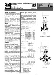
<strong>SVI</strong> <strong>II</strong> AP Dimensions and Weights<br />
Figure 3 below illustrates the dimensions and weight of the <strong>SVI</strong> <strong>II</strong> AP.<br />
203.93 mm<br />
8.03 in<br />
122.55 mm<br />
4.825 in<br />
(74.97 mm)<br />
(2.95 in)<br />
125.33 mm<br />
4.93 in<br />
145.37 mm<br />
5.72 in<br />
23.00 mm<br />
.90 in<br />
34.00 mm<br />
1.34 in<br />
Center of Gravity<br />
34.00 mm<br />
1.34 in<br />
96.56 mm<br />
3.8 in<br />
1.90 mm<br />
0.075 in<br />
106.36 mm<br />
4.19 in<br />
53.18 mm<br />
2.1 in<br />
74.97 mm<br />
2.95 in<br />
38.10 mm<br />
1.5 in<br />
47.58 mm<br />
1.87 in<br />
Weight Standard - 7.4 lbs (3.357 kg)<br />
Weight Stainless Steel - 16 lbs/ 7.257 kg<br />
(1.90 mm)<br />
(0.075 in)<br />
Figure 3<br />
<strong>SVI</strong> <strong>II</strong> AP Dimensions<br />
6
Installation and Set Up<br />
Pre-Installation Issues<br />
Pre-Installation<br />
Issues<br />
Storage<br />
If the <strong>SVI</strong> <strong>II</strong> AP is stored for a long duration, you must keep the housing sealed<br />
against weather, fluids, particles, and insects. To prevent damage to the <strong>SVI</strong> <strong>II</strong><br />
AP:<br />
<br />
<br />
<br />
Use the plugs provided with shipment to plug the ¼ NPT air<br />
connections, on the positioner and on the air filter regulator set.<br />
Do not allow standing water to accumulate.<br />
Observe storage temperature requirements.<br />
Unpacking<br />
Please exercise care when unpacking the control valve and its mounted<br />
accessories. In the <strong>SVI</strong> <strong>II</strong> AP container you should find a CD-ROM with<br />
ValVue 2.4 Lite, ValVue 2.4 Trial Version, and manuals.<br />
Installation<br />
Steps<br />
If you experience problems that are not documented in this guide call<br />
Masoneilan or your local Masoneilan representative. Sales offices are listed<br />
on the last page of this document.<br />
The steps necessary to complete the <strong>SVI</strong> <strong>II</strong> AP installation and software setup<br />
are outlined in Table 1 below.<br />
Step<br />
No.<br />
Table 1 <strong>SVI</strong> <strong>II</strong> AP Installation Steps<br />
Procedure<br />
Reference<br />
1 Attach mounting bracket to the actuator. See 10 for rotary valve and 14 for<br />
reciprocating valve instructions.<br />
2 Install the <strong>SVI</strong> <strong>II</strong> AP magnetic assembly (rotary valves<br />
only).<br />
3 Assemble the <strong>SVI</strong> <strong>II</strong> AP on the bracket that is<br />
mounted to the valve actuator.<br />
See 13 for instructions.<br />
See 10 for rotary valve and 14 for<br />
reciprocating valve instructions.<br />
4 Install the Remote Position Sensor, if necessary. See 18 for instructions.<br />
5 Connect the pneumatic tubing to the <strong>SVI</strong> <strong>II</strong> AP. See 23 for instructions.<br />
6 Connect the air supply to the <strong>SVI</strong> <strong>II</strong> AP. See 28 for instructions.<br />
7 Connect the positioner to the HART Control Loop<br />
segment by installing the <strong>SVI</strong> <strong>II</strong> AP wiring.<br />
See 28 for instructions.<br />
7
Masoneilan Dresser<br />
<strong>SVI</strong> <strong>II</strong> AP <strong>Instruc</strong>tion <strong>Man</strong>ual<br />
Step<br />
No.<br />
Table 1 <strong>SVI</strong> <strong>II</strong> AP Installation Steps<br />
Procedure<br />
Reference<br />
8 Configure/Calibrate using LCD Pushbutton display See 57 for instructions<br />
Configure/Calibrate using a Hart Hand Held<br />
Communicator.<br />
Configure/Calibrate using ValVue 2.4<br />
See 63 for instructions<br />
See 64 for instructions.<br />
Failure to adhere to the requirements listed in this manual may cause loss of<br />
life and property.<br />
Before installing, using, or carrying out any maintenance tasks associated with<br />
this instrument, READ THE INSTRUCTIONS CAREFULLY.<br />
Installation<br />
Notes<br />
1. The installation should comply with local and national regulations<br />
concerning the compressed air supply and <strong>SVI</strong> <strong>II</strong> AP instrument.<br />
2. Installation and maintenance must be performed only by qualified<br />
personnel. <strong>SVI</strong> <strong>II</strong> AP repairs beyond the scope of this manual must<br />
be performed by Masoneilan.<br />
3. Area Classification, Protection Type, Temperature Class, Gas<br />
Group, and Ingress protection must conform to the data indicated on<br />
the label.<br />
4. Wiring and conduit must conform to all local and national codes<br />
governing the installation. Wiring must be rated for at least 85º C<br />
(185º F) or 5º C (41º F) above max ambient, whichever is greater.<br />
5. Approved wire seals against ingress of water and dust are required<br />
and the 1/2 inch NPT fittings must be sealed with tape or pipe dope<br />
in order to meet the highest level of ingress protection.<br />
Before Powering Up<br />
Before powering up the <strong>SVI</strong> <strong>II</strong> AP:<br />
1. Verify that the pneumatic connections and electronic cover screws<br />
are tightened. This is important to maintain the ingress protection<br />
level and the integrity of the flameproof enclosure.<br />
2. If the installation is Intrinsically Safe, then check that the proper<br />
barriers are installed and the field wiring meets local and national<br />
codes for an IS installation.<br />
8
Installation and Set Up<br />
Installation Notes<br />
Mounting the Positioner<br />
3. If the installation is Non-Incendive, then check that all the electrical<br />
connections are to approved devices and wiring meets local and<br />
national codes.<br />
4. Verify that the markings on the label are consistent with the<br />
application.<br />
Note: For Hazardous Location Installation information refer to Appendix A,<br />
Specifications and References<br />
Before installing, using, or carrying out any maintenance tasks associated with<br />
this instrument, READ THE INSTRUCTIONS CAREFULLY.<br />
This guide provides installation instructions for mounting an <strong>SVI</strong> <strong>II</strong> AP on both<br />
rotary and reciprocating actuated valves. The mounting process can be<br />
broken down into the following:<br />
<br />
<br />
<br />
Attach the mounting bracket to the actuator.<br />
Install the magnetic assembly (rotary only).<br />
Assemble the <strong>SVI</strong> <strong>II</strong> AP on the mounting bracket.<br />
Note:<br />
The <strong>SVI</strong> <strong>II</strong> AP should be mounted with the conduit connections down<br />
in order to facilitate drainage of condensate from the conduit.<br />
Necessary Precautions<br />
Filter Regulator and Tubing<br />
To avoid injury or the process being affected when installing or replacing a<br />
positioner on a control valve, ensure that:<br />
<br />
<br />
<br />
<br />
If the valve is located in a hazardous area make sure the area<br />
has been certified as “safe” or that all electrical power to the<br />
area has been disconnected before removing any covers or<br />
disconnecting any leads.<br />
Shut off air supply to the actuator and to any valve mounted<br />
equipment.<br />
Ensure the valve is isolated from the process by either shutting<br />
off the process or using bypass valves for isolation. Tag shutoff<br />
or bypass valves to guard against a “turn-on” while work is in<br />
progress.<br />
Purge air from actuator and check that valve is in its<br />
unenergized position.<br />
The use of a Masoneilan filter regulator with a 5-micron filter is recommended<br />
for the air supply. Tubing used between filter regulator, <strong>SVI</strong> <strong>II</strong> AP and actuator<br />
should be 1⁄4 inch (6.35 mm) minimum with 3⁄8 inch (9.53 mm) used for larger<br />
actuators. The use of a soft setting anaerobic hydraulic seal such as Loctite<br />
Hydraulic Seal 542 is recommended for sealing the pneumatic pipe threads.<br />
Follow manufacturers instructions.<br />
9
Masoneilan Dresser<br />
<strong>SVI</strong> <strong>II</strong> AP <strong>Instruc</strong>tion <strong>Man</strong>ual<br />
Note:<br />
Maximum allowable air supply pressure to the <strong>SVI</strong> <strong>II</strong> AP varies<br />
according to actuator and valve size and type. See pressure drop<br />
tables in valve specification sheets to determine correct positioner<br />
supply pressure. Minimum supply pressure should be 5 to 10 psi<br />
(.345 bar - .69 bar) (34.485 - 68.97 kPa) above maximum spring<br />
pressure.<br />
Mounting the<br />
<strong>SVI</strong> <strong>II</strong> AP on<br />
Rotary Valves<br />
This procedure is used to mount the <strong>SVI</strong> <strong>II</strong> AP on rotary control valves that<br />
have less than 60 degrees rotation, such as a Camflex ® or a Varimax ® . For<br />
valves that have rotation greater than 60 degrees refer to “Rotary - 90 Degree”<br />
on page 13<br />
Required Tools<br />
The following tools are needed to complete the rotary valve installation:<br />
<br />
<br />
<br />
<br />
To mount the <strong>SVI</strong> <strong>II</strong> AP:<br />
3⁄16 inch Hex Key with tee handle<br />
5⁄32 inch Hex Key<br />
3 mm, 4mm, 5mm Hex Key<br />
7⁄16 inch Wrench<br />
1. Attach the <strong>SVI</strong> <strong>II</strong> AP rotary mounting bracket to the valve actuator<br />
using two (2) 5⁄16 - 18 UNC flat-head cap screws. The<br />
<strong>SVI</strong> <strong>II</strong> AP will be mounted as shown in Figure 5 on page 11, ATO or<br />
in Figure 6 on page 12, ATC. In the preferred mounting position, the<br />
long end of the mounting bracket is on your left when facing the<br />
actuator, for any position of the valve and actuator.<br />
2. Bolt the extension shaft to the valve position take-off shaft using a<br />
1⁄4 - 28 UNF socket flathead screw. Secure the machine screw<br />
holding the extension shaft with a torque of 144 in-lbs (16.269 N-m).<br />
3. Upon internal valve pressure the thrust shaft is pushed out to the<br />
mechanical stops, usually a thrust bearing. On valves where the<br />
valve position take-off is mounted directly on the end of the plug<br />
shaft, a Camflex for example, the shaft must be bearing on its stop to<br />
properly set up the <strong>SVI</strong> <strong>II</strong> AP positioner. During hydrostatic testing<br />
the shaft is thrust to its stop and a normally tightened packing will<br />
retain it in that position.<br />
4. On vacuum service, the valve shaft may be drawn into the body by<br />
the vacuum acting on the shaft, but the magnetic coupling must be<br />
assembled flush with the mounting bracket with the shaft pulled fully<br />
out to its thrust bearing. Check that the endplay from the vacuum<br />
position to the fully extended position is less than 0.06 in. (1.524<br />
mm)<br />
5. Slide the magnet holder into the extension shaft. The location of the<br />
magnets is in the ring of the magnet holder. The magnetic axis is the<br />
imaginary line through the center of both magnets.<br />
6. Rotate the magnet holder so that the magnet axis is vertical when<br />
the valve is in the closed position. See Figure 5 and Figure 6.<br />
10
Installation and Set Up<br />
Mounting the <strong>SVI</strong> <strong>II</strong> AP on Rotary Valves<br />
7. Align the end of the magnet holder flush with the end of the<br />
mounting bracket. Secure the magnet holder with two M6 set<br />
screws.<br />
8. Slide the V-Seal over the magnet holder.<br />
9. Secure the <strong>SVI</strong> <strong>II</strong> AP onto the mounting bracket using four M6 x 20<br />
mm Socket Head Cap Screws.<br />
10. Ensure no interference exists with the position sensor protrusion.<br />
11. Ensure that the V-Seal makes contact with the skirt around the<br />
position sensor protrusion on <strong>SVI</strong> <strong>II</strong> AP housing.<br />
Figure 4<br />
Camflex with Mounting Bracket (Side View)<br />
Figure 5<br />
Camflex ATO Mounting (Front View)<br />
11
Masoneilan Dresser<br />
<strong>SVI</strong> <strong>II</strong> AP <strong>Instruc</strong>tion <strong>Man</strong>ual<br />
Figure 6<br />
Mounting Bracket on “Air-to-Close” Actuator<br />
Table 2 Magnet Orientation on Rotary Actuators<br />
Rotary Actuator Type<br />
Magnet Setting - ATO<br />
Magnet Setting -<br />
ATC<br />
Camflex Actuator is energized __ Magnet Axis is Vertical<br />
Figure 6<br />
Camflex Actuator is de-energized<br />
Varimax®<br />
Actuator is energized<br />
Varimax<br />
Actuator is de-energized<br />
Model 33 in clockwise to open valve<br />
Actuator is de-energized<br />
(36000 Series Control Ball, 37000 MiniTork ® )<br />
Magnet Axis is Vertical<br />
Figure 5<br />
__<br />
Magnet Axis is Vertical<br />
Magnet axis 45 degrees to<br />
right of vertical position in<br />
Figure 7<br />
__<br />
Magnet Axis is Vertical<br />
__<br />
Magnet axis 45 degrees<br />
to right of vertical<br />
Double acting cylinders at mid-travel Magnet Axis Vertical Magnet Axis Vertical<br />
12
Installation and Set Up<br />
Mounting the <strong>SVI</strong> <strong>II</strong> AP on Rotary Valves<br />
Figure 7<br />
Model 33 Actuator<br />
Rotary - 90 Degree<br />
For actuators with 60 to 120 degrees rotation, follow the instructions in<br />
“Mounting the <strong>SVI</strong> <strong>II</strong> AP on Rotary Valves” on page 10 except mount the<br />
magnet at plus or minus 45 degrees while the actuator de-energized as<br />
shown in Figure 7 on page 13.<br />
Magnet Orientation on Rotary Valve Shafts<br />
The same mounting hardware is used for Models 35, 30 actuators. For each<br />
actuator type the magnetic coupling must be properly oriented to the active<br />
sensing angle of the positioners Hall Effect sensor. The active range of the<br />
Hall-Effect sensor is plus⁄minus 70 degrees from the null magnet axis. If the<br />
total valve travel is less than 60 degrees, allowing a margin for tolerances, the<br />
best accuracy is achieved by mounting the magnet with the axis vertical in the<br />
valve-closed position. Note the location of the magnets in the ring of the<br />
magnet holder. The axis of the magnets is the line through the centers of both<br />
magnets. Mount the magnet holder with the magnet axis vertical on the 35, 30<br />
when the valve is closed. If travel of the valve exceeds 60 degrees, the<br />
magnet must be assembled to the rotary valve shaft so that the magnet axis is<br />
vertical when the valve is at mid-scale.<br />
Dismantling the <strong>SVI</strong> <strong>II</strong> AP from Rotary Valves<br />
Before carrying out any work on the device, power off the instrument or make<br />
sure that the device’s location conditions for potentially explosive atmosphere<br />
permit the safe opening of the cover.<br />
To remove the <strong>SVI</strong> <strong>II</strong> AP positioner from a rotary valve perform Steps 1 - 8 on<br />
page 7 in reverse.<br />
13
Masoneilan Dresser<br />
<strong>SVI</strong> <strong>II</strong> AP <strong>Instruc</strong>tion <strong>Man</strong>ual<br />
Mounting the<br />
<strong>SVI</strong> <strong>II</strong> AP on<br />
Reciprocating<br />
Valves<br />
This section describes the procedure for mounting the <strong>SVI</strong> <strong>II</strong> AP on<br />
Reciprocating Valves (using Masoneilan’s 87⁄88 Multi-Spring actuators as an<br />
example).<br />
Tools required:<br />
<br />
<br />
<br />
<br />
<br />
7⁄16 inch Combination Wrench (2 required)<br />
3⁄8 inch Combination Wrench<br />
1⁄2 inch Combination Wrench<br />
Phillips Head Screw Driver<br />
5 mm Hex Key Wrench<br />
Mounting the <strong>SVI</strong> <strong>II</strong> AP on a Reciprocating Actuator<br />
1. Ensure that the lever is pinned to the magnet assembly and held<br />
securely by an M5 flat head screw to ensure that the magnet axis is<br />
vertical when the lever is in the valve closed position. Tighten the<br />
lever screw securely.<br />
2. Mount the <strong>SVI</strong> <strong>II</strong> AP reciprocating mounting bracket to the actuator<br />
using two (2) 5⁄16 - 18 UNC cap screws. The mounting location of<br />
the bracket depends on the size and stroke of the actuator. Refer to<br />
Figure 9 on page 16 and Table 3 on page 16.<br />
3. Select mounting hole A, B, C or D for the stroke of the valve. For<br />
example, hole B is shown in Figure 10 on page 16 for a size 10<br />
actuator with 1.0 inch stroke. Unless otherwise specified, the <strong>SVI</strong> <strong>II</strong><br />
AP mounting assumes that the actuator is in the normal upright<br />
position. The mounting hole in the slotted opening of the mounting<br />
bracket must be left when facing the actuator, with the actuator in the<br />
upright position.<br />
4. Thread the take-off rod to the actuator stem connector. Refer to<br />
Figure 11 on page 17. Ensure that the travel pointer located on the<br />
coupling is correctly positioned.<br />
5. Attach the right hand threaded rod end to the <strong>SVI</strong> <strong>II</strong> AP lever using a<br />
1⁄4 - 20 x 1 inch cap screw and nut as shown. The lever hole position<br />
to be used depends upon the specific valve stroke. Refer to Figure<br />
10 on page 16 and the Reciprocating Valve Linkage Selection, Table<br />
3 on page 16.<br />
6. Thread the right hand lock nut and turnbuckle onto the right hand rod<br />
end approximately two turns. Turnbuckle length is a function of<br />
actuator size. (Refer to Table 3 on page 16.)<br />
7. Secure the magnet housing assembly, including the lever and right<br />
hand rod end, to the bracket using four M5 X 10 mm flat head<br />
screws.<br />
8. Attach the left hand threaded rod end to the take-off rod with<br />
1⁄4 - 20 UNC nut and thread the left hand lock nut onto the rod end.<br />
9. Move the valve to its closed position. For air to extend, this requires<br />
using air pressure in the actuator to fully stroke the actuator. For air<br />
to retract, actuators vent the actuator of air pressure.<br />
10. Thread the turnbuckle onto the left hand threaded rod end. Refer to<br />
Figure 11 on page 17.<br />
14
Installation and Set Up<br />
Mounting the <strong>SVI</strong> <strong>II</strong> AP on Reciprocating Valves<br />
11. Adjust the turnbuckle until the hole in the <strong>SVI</strong> <strong>II</strong> AP lever is aligned<br />
with the indicating hole in the bracket. Tighten both turnbuckle lock<br />
nuts. (See Figure 9 on page 16.)<br />
12. Mount the <strong>SVI</strong> <strong>II</strong> AP to the bracket and secure with four M6 socket<br />
head cap screws.<br />
Figure 8<br />
Magnet Holder for Reciprocating Valves<br />
15
Masoneilan Dresser<br />
<strong>SVI</strong> <strong>II</strong> AP <strong>Instruc</strong>tion <strong>Man</strong>ual<br />
Figure 9<br />
Reciprocating Valve Mounting Bracket<br />
Figure 10 Lever for Model 87/88 Multispring Actuator<br />
Table 3 Reciprocating Valve Mounting Hole and Turnbuckle Length<br />
Actuator Size<br />
Masoneilan<br />
Stroke Mounting Hole Lever Hole Turnbuckle Length<br />
6 and 10 0.5 - 0.8 inch<br />
(12.7 - 20.32 mm)<br />
10 0.5 - 0.8 inch<br />
(12.7 - 20.32 mm)<br />
10 >0.8 – 1.5 inch<br />
(20.32 - 41.5 mm)<br />
16 0.5 - 0.8 inch<br />
(12.7 - 20.32 mm)<br />
16 >0.8 – 1.5 inch<br />
(20.32 - 41.5 mm)<br />
16 >1.5 – 2.5 inch<br />
(41.5 - 63.5 mm)<br />
23 0.5 - 0.8 inch<br />
(12.7 - 20.32 mm)<br />
23 >0.8 – 1.5 inch<br />
(20.32 - 41.5 mm)<br />
23 >1.5 – 2.5 inch<br />
(41.5 - 63.5 mm)<br />
A A 1.25 inch<br />
(31.75 mm)<br />
A A 1.25 inch<br />
(31.75 mm)<br />
B B 1.25 inch<br />
(31.75 mm)<br />
B A 2.90 inch<br />
(73.66 mm)<br />
C B 2.90 inch<br />
(73.66 mm)<br />
D C 2.90 inch<br />
(73.66 mm)<br />
B A 5.25 inch<br />
(133.35 mm)<br />
C B 5.25 inch<br />
(133.35 mm)<br />
D C 5.25 inch<br />
(133.35 mm)<br />
16
Installation and Set Up<br />
Mounting the <strong>SVI</strong> <strong>II</strong> AP on Reciprocating Valves<br />
Figure 11 Reciprocating Linkage<br />
Dismantling the <strong>SVI</strong> <strong>II</strong> AP from Reciprocating Valves<br />
Before carrying out any work on the device, power off the instrument or make<br />
sure that the local conditions for potentially explosive atmosphere permit the<br />
safe opening of the cover.<br />
To remove the <strong>SVI</strong> <strong>II</strong> AP positioner from a reciprocating valve perform Steps 1<br />
- 12 on pages 10 - 11 in reverse.<br />
17
Masoneilan Dresser<br />
<strong>SVI</strong> <strong>II</strong> AP <strong>Instruc</strong>tion <strong>Man</strong>ual<br />
Installing the<br />
<strong>SVI</strong> <strong>II</strong> AP<br />
Remote<br />
Position Sensor<br />
An option that is available for the <strong>SVI</strong> <strong>II</strong> AP is the Remote Position Sensor.<br />
The Remote Position Sensor is a remotely mounted position-sensing device,<br />
that is connected electrically to an <strong>SVI</strong> <strong>II</strong> AP valve positioner. It is used as<br />
position feedback in applications where direct mounting of an <strong>SVI</strong> <strong>II</strong> AP to a<br />
valve actuator is not practical due, typically but not limited to, extreme<br />
vibration, heat or radiation.<br />
The Remote Position Sensor is a potentiometer located in an enclosure which<br />
can be mounted on a valve or damper to indicate stem position when<br />
connected to a suitable receiver. There is a three wire connection provided on<br />
a screw terminal block to interconnect to the receiving device.<br />
The <strong>SVI</strong> <strong>II</strong> AP Remote Position Sensor is suitable for installation indoors and<br />
outdoors in an industrial environment. Mounting kits are provided to permit<br />
mounting on a variety of valves.<br />
Table 4 Remote Position Sensor Specifications<br />
Operating Temperature Range<br />
-55°C to 125°C (-67°F to 257°F)<br />
Vibration Limits Vibration resistant according to ISA 75.13<br />
Maximum Distance to <strong>SVI</strong> <strong>II</strong> AP<br />
Recommended Wiring<br />
30 M (100 Ft.) maximum recommended, for setups with distances of<br />
more than 30 M consult the factory<br />
Shielded Cable up to 14 AWG<br />
Do not remove the instrument cover or connect to an electrical circuit in a<br />
Hazardous Area unless the power is disconnected.<br />
Remote Position Sensor Mounting <strong>Instruc</strong>tions<br />
1. Comply with current national and local regulations for electrical<br />
installation work.<br />
2. Comply with national and local explosive atmosphere regulations.<br />
3. Before carrying out any work on the device, power off the instrument<br />
or make sure that the local conditions for potentially explosive<br />
atmosphere permit the safe opening of the cover.<br />
Tools Needed<br />
<br />
<br />
<br />
<br />
7/16 inch open end wrench<br />
6 mm hex wrench<br />
2.5 mm hex wrench<br />
Blade screwdriver<br />
18
Installation and Set Up<br />
Installing the <strong>SVI</strong> <strong>II</strong> AP Remote Position Sensor<br />
Note:<br />
The instructions below cover mounting the Remote Mount Sensor to<br />
both reciprocating and rotary actuators. The two mounting kits share<br />
only one part; the ¼-20 hex head cap screws. Although the assembly<br />
steps are similar, differences are noted. Refer to Figure 12 on page<br />
19 when reading these instructions for proper orientation.<br />
1. Fasten the mounting bracket to the actuator yoke<br />
a. For reciprocating actuators, use the (2) 5/16-18 hex head bolts<br />
supplied.<br />
b. For rotary actuators, use the (2) 5/16-18 hex socket<br />
countersunk screws supplied.<br />
2. Connect the Remote Mount Sensor (RMS) to the mounting bracket<br />
using (4) ¼-20 hex head cap screws. Orient the RMS as shown in<br />
the figure below, such that the conduit opening faces the ground.<br />
3. Attach the feedback lever to the RMS output shaft.<br />
a. For reciprocating mounting; Slip the feedback lever onto the<br />
RMS output shaft, and thread the M5 set screw into the hole.<br />
Be sure to align the setscrew hole of the feedback lever with the<br />
flat of the RMS output shaft such that the setscrew contacts the<br />
flat. Next, connect the take-off rod to the split clamp of the<br />
actuator stem. Finally, connect one end of the turnbuckle to the<br />
feedback lever, and the other end to the take-off rod. (Refer to<br />
Table 5 on page 20 for turnbuckle length.)<br />
b. For rotary mounting; First connect the feedback lever (with the<br />
pin) to the actuator shaft (protruding from the actuator yoke)<br />
using the supplied hardware. This hardware includes a spacer,<br />
a spring washer and a ¼-28 hex head cap screw. Next, attach<br />
the second feedback lever (with the slot) to the RMS output<br />
shaft and at the same time, insert the pin of the first feedback<br />
lever into the slot. It may be necessary to loosen some of the<br />
parts in order to get everything to align properly. Finally, thread<br />
the M4 socket head cap screw into the setscrew hole of the<br />
second feedback lever making sure it contacts the flat of the<br />
RMS output shaft.<br />
Lever<br />
Lever<br />
Bracket<br />
Turnbuckle<br />
Remote Position Sensor Mounted<br />
on Reciprocating Actuator<br />
Bracket<br />
Remote Position Sensor Mounted<br />
on Rotary Actuator<br />
Figure 12 Remote Position Sensor Mounting<br />
19
Masoneilan Dresser<br />
<strong>SVI</strong> <strong>II</strong> AP <strong>Instruc</strong>tion <strong>Man</strong>ual<br />
Table 5 Remote Position Sensor Turnbuckle Length<br />
Actuator<br />
Size<br />
Stroke<br />
Turnbuckle Length<br />
6 and 10 0.5 - 0.8 inch (12.7 - 20.32 mm) 1.25 inch (31.75 mm)<br />
10 0.5 - 0.8 inch (12.7 - 20.32 mm) 1.25 inch (31.75 mm)<br />
10 >0.8 – 1.5 inch (20.32 - 41.5 mm) 1.25 inch (31.75 mm)<br />
16 0.5 - 0.8 inch (12.7 - 20.32 mm) 2.90 inch (73.66 mm)<br />
16 >0.8 – 1.5 inch (20.32 - 41.5 mm) 2.90 inch (73.66 mm)<br />
16 >1.5 – 2.5 inch (41.5 - 63.5 mm) 2.90 inch (73.66 mm)<br />
23 0.5 - 0.8 inch (12.7 - 20.32 mm) 5.25 inch (133.35 mm)<br />
23 >0.8 – 1.5 inch (20.32 - 41.5 mm) 5.25 inch (133.35 mm)<br />
23 >1.5 – 2.5 inch (41.5 - 63.5 mm) 5.25 inch (133.35 mm)<br />
4. Remove the M8 cover-retention screw of the RMS and unscrew the<br />
cover to gain access to the terminal strip.<br />
5. Route the cable from the <strong>SVI</strong> <strong>II</strong> AP to the RMS and thread the cable<br />
through the conduit at the bottom of the housing.<br />
6. Using a blade screwdriver, loosen the screws on the terminal strip<br />
and connect the wires; black-to-black, brown-to-brown and red-tored.<br />
Then retighten the screws. Refer to Figure 13 on page 21 for<br />
Remote Position Sensor Wiring.<br />
7. Connect the cable’s shielding drain wire to the unlabeled terminal.<br />
8. Screw on the RMS cover and replace the M8 cover-retention screw.<br />
9. At the other end of the cable, insert the ferrules into the terminal<br />
labeled “REMOTE”; black-to-black, brown-to-brown and red-to-red.<br />
When performing this step, be careful not to side-load the terminal<br />
levers.<br />
20
Installation and Set Up<br />
Installing the <strong>SVI</strong> <strong>II</strong> AP Remote Position Sensor<br />
Remote Position Sensor<br />
with Cover Removed<br />
Step 1<br />
Connect Drain Wire<br />
to Open Terminal<br />
Ferrules<br />
Step 2<br />
When connecting cable to<br />
Remote Position Sensor make sure wire<br />
colors match:<br />
- Red to Red<br />
- Brown to Brown<br />
- Black to Black<br />
Step 3<br />
Insert Ferrules into Remote Mount<br />
connector according to<br />
the chart at the right:<br />
Wiring <strong>Instruc</strong>tions<br />
Wire Color<br />
Red<br />
Brown<br />
Black<br />
<strong>SVI</strong> <strong>II</strong> AP Terminal Number<br />
1<br />
2<br />
3<br />
Function<br />
Positive<br />
Signal<br />
Ground<br />
Remote Mount Connector<br />
Figure 13 Remote Position Sensor (Cover Removed) and Wiring<br />
21
Masoneilan Dresser<br />
<strong>SVI</strong> <strong>II</strong> AP <strong>Instruc</strong>tion <strong>Man</strong>ual<br />
Configuring the <strong>SVI</strong> <strong>II</strong> AP for Remote Position Sensing<br />
After the Remote Position Sensor is installed and cabled to the <strong>SVI</strong> <strong>II</strong> AP, the<br />
<strong>SVI</strong> <strong>II</strong> AP needs to be configured so that valve position is sensed by Remote<br />
Position Sensor. A digital communication software tool is provided on the CD<br />
shipped with the <strong>SVI</strong> <strong>II</strong> AP for this purpose. First you must install the software<br />
tool, <strong>SVI</strong> <strong>II</strong> Assistant, from the CD and then using the tool, configure the <strong>SVI</strong> <strong>II</strong><br />
AP. (You may also download <strong>SVI</strong> <strong>II</strong> Assistant from the Masoneilan web site,<br />
www.masoneilan.com, downloads.)<br />
To install <strong>SVI</strong> <strong>II</strong> Assistant (see Figure 14 below):<br />
1. From the CD select and click on "View Other Tool".<br />
2. The CD will then display other available software tools. Select and<br />
click on "Install <strong>SVI</strong> <strong>II</strong> Assistant ....". The program will automatically<br />
install.<br />
Selecting "View Other Tool"<br />
Installing <strong>SVI</strong> <strong>II</strong> Assistant<br />
Figure 14 Installing <strong>SVI</strong> <strong>II</strong> Assistant from CD<br />
22
Installation and Set Up<br />
Installing the <strong>SVI</strong> <strong>II</strong> AP Remote Position Sensor<br />
Configuring the <strong>SVI</strong> <strong>II</strong> AP Using <strong>SVI</strong> <strong>II</strong> Assistant<br />
To configure the <strong>SVI</strong> <strong>II</strong> AP:<br />
1. Start <strong>SVI</strong> <strong>II</strong> Assistant Standard by clicking the desktop icon or by<br />
selecting the program through the Start menu.<br />
2. When <strong>SVI</strong> <strong>II</strong> Assistant launches, the first screen displayed is<br />
"Connection". On the Connection screen, click on "Connect" as<br />
shown in Figure 15 below.<br />
3. <strong>SVI</strong> <strong>II</strong> Assistant will search for the <strong>SVI</strong> <strong>II</strong> AP (to which the Remote<br />
Position Sensor is connected), connect the device to the software<br />
and display device information as shown in Figure 15 below.<br />
4. After the <strong>SVI</strong> <strong>II</strong> AP has been connected, select the "Options" tab to<br />
display the "Options" screen as shown below.<br />
5. On the Options screen select "Remote PO" by clicking in the<br />
checkbox at the left.<br />
6. To activate the Remote Position Sensor click "Change Options" as<br />
shown in the figure below.<br />
7. <strong>SVI</strong> <strong>II</strong> Assistant will change control to the Remote Position Sensor<br />
and display the message shown below. Click "OK" to continue.<br />
<strong>SVI</strong>-<strong>II</strong> Assistant Connection Screen<br />
<strong>SVI</strong> <strong>II</strong> AP Device Connected<br />
Options Screen - Remote Position Sensor Selected<br />
Device Set to Use Remote Position Sensor Message<br />
Figure 15 <strong>SVI</strong>-<strong>II</strong> Assistant - Commissioning the Remote Position Sensor<br />
23
Masoneilan Dresser<br />
<strong>SVI</strong> <strong>II</strong> AP <strong>Instruc</strong>tion <strong>Man</strong>ual<br />
Connecting the<br />
Tubing and Air<br />
Supply<br />
The last step in hardware installation for the <strong>SVI</strong> <strong>II</strong> AP is to connect the air<br />
supply to the positioner. This section describes the process for connecting the<br />
tubing and air supply to a single and double acting positioner.<br />
Isolate the valve from the process and disconnect air tubing from the<br />
positioner. Disconnect air fully to avoid injury or process damage.<br />
1. Install the tubing to the air supply port (S←).<br />
2. For a single acting actuator - pipe the outbound air from the output<br />
pressure port (←I) to the actuator.<br />
3. For a double acting actuator - pipe output pressure port one (←I) for<br />
one side of the actuator and output pressure port two (←<strong>II</strong>) for the<br />
other side of the actuator.<br />
4. Air supply:<br />
Supply pressure for single acting <strong>SVI</strong> <strong>II</strong> AP:<br />
20 -100 psi (1.4 - 6.9 bar) (138 - 690 kPa)<br />
Supply pressure for double acting <strong>SVI</strong> <strong>II</strong> AP:<br />
25 - 150 psi (1.73 - 10.4 bar) (0 - 1035 kPa)<br />
Minimum tubing diameter 1⁄4 inch (6mmx4mm)<br />
Note:<br />
The <strong>SVI</strong> <strong>II</strong> AP Digital Positioner is designed to operate with clean, dry,<br />
oil-free, instrument grade air to ANSI-ISA-57.3 1975 (R1981) or ISA-<br />
S7.3-1975 (R1981) or with a sweet natural gas supply (<strong>SVI</strong> <strong>II</strong> AP<br />
models <strong>SVI</strong> <strong>II</strong> AP-2 through <strong>SVI</strong> <strong>II</strong> AP-3).<br />
Table 6 Air Supply Requirements<br />
Dew Point<br />
Particulate Matter<br />
Oil Content<br />
Contaminants<br />
At least 18° F (10° C) below minimum anticipated ambient temperature<br />
Filtered to 5 microns<br />
Less than 1 ppm w/w<br />
Free of all corrosive contaminants<br />
24
Installation and Set Up<br />
Connecting the Tubing and Air Supply<br />
Do not use pipe thread sealant tape on pneumatic fittings. It may shred into<br />
small particles that can cause instrument malfunction.<br />
Never exceed the lower of actuator maximum rated supply pressure 100 psi<br />
(6.9 bar, 689.7 kPa) for single acting or 150 psi (10.4 bar, 1035 kPa) for<br />
double acting positioner. Damage to equipment or injury to personnel can<br />
result.<br />
Single Acting Positioner<br />
Remove any excess pipe thread sealant from the first and second threads to<br />
prevent uncured sealant from entering the air lines.<br />
The supply and output connections for the <strong>SVI</strong> <strong>II</strong> AP, located on bottom of the<br />
pneumatic block, are tapped 1⁄4 inch NPT. Output is toward the front, supply<br />
is toward the back. Two pressure gauges, output on top, supply on bottom,<br />
are located on the front of the pneumatic block.<br />
Maximum allowable air supply pressure to the <strong>SVI</strong> <strong>II</strong> AP varies according to<br />
actuator, valve size, and valve type. See Pressure Drop tables in valve<br />
specification sheets to determine the correct positioner supply pressure.<br />
Minimum supply pressure should be 5 psi to 10 psi (.345 bar - .69 bar) (34.485<br />
- 68.97 kPa) above maximum spring range but may not exceed the rated<br />
actuator pressure.<br />
1. Pipe the outbound air from the output pressure port (←I) to the<br />
valve actuator.<br />
2. Connect air supply and actuator outputs (1⁄4 inch NPT). Supply<br />
pressure is 20 -100 psi (1.4 - 6.9 bar) (138 - 690 kPa). Minimum<br />
tubing diameter 1⁄4 inch (6mmx4mm).<br />
25
Masoneilan Dresser<br />
<strong>SVI</strong> <strong>II</strong> AP <strong>Instruc</strong>tion <strong>Man</strong>ual<br />
Supply<br />
Figure 16 Air Ports on Single Acting Positioner<br />
Output<br />
Double Acting Positioner<br />
The Double Acting (DA) relay has a pair of opposed pneumatic outputs. When<br />
Output 1 delivers air to one side of the actuator, Output 2 vents air from the<br />
opposite side of the actuator piston. The volume of air trapped in each<br />
determines the position of the actuator.<br />
The Action (ATO or ATC) is applied with respect to Output 1. When Output 1 is<br />
connected to deliver air to extend the actuator, the action is ATC, on a downseating<br />
valve.<br />
1. Connect Output 1, labeled “(←I)” to the inlet port of the actuator and<br />
Output 2 labeled “(←<strong>II</strong>)” to the opposing actuator port (see Figure<br />
17 below).<br />
2. Connect air supply and actuator outputs (1⁄4 inch NPT). Supply<br />
pressure is 25 - 150 psi (1.4 - 10.4 bar) (138 - 1035 kPa). Minimum<br />
tubing diameter 1⁄4 inch (6mmx4mm)<br />
26
Installation and Set Up<br />
Connecting the Tubing and Air Supply<br />
Output I<br />
Supply<br />
Output <strong>II</strong><br />
Figure 17 Air Ports on Double Acting Positioner<br />
Balance Pressure<br />
Actuator Piping<br />
The double-acting relay is designed to deliver pressure on both sides of a<br />
piston type actuator, so that the cylinder can provide the required thrust and<br />
stiffness. This stiffness is factory adjusted to 70% of the supply pressure.<br />
This means that, without any unbalance forces from the valve stem, both<br />
outputs will deliver roughly 70% of air supply pressure.<br />
Although it is not recommended, the stiffness can be adjusted by moving the<br />
Adjustable Seat assembly up or down.<br />
Connect Output 1, labelled “ACT 1” to the inlet port of the actuator in<br />
accordance with Table 7 below. Output 2 labelled “ACT 2” connects to the<br />
opposing actuator port.<br />
27
Masoneilan Dresser<br />
<strong>SVI</strong> <strong>II</strong> AP <strong>Instruc</strong>tion <strong>Man</strong>ual<br />
Table 7 Double Acting Positioner ATO⁄ATC Settings for<br />
Reciprocating Valves<br />
Actuator Style<br />
Required<br />
Position on<br />
Loss of Input<br />
Current<br />
Connection<br />
to Output 1<br />
Action of<br />
Positioner<br />
Notes<br />
Piston without spring Closed To retract ATO Requires backup air supply or<br />
reserve tank to failsafe the valve<br />
Piston without spring Open To extend ATC Requires backup air supply or<br />
reserve tank to failsafe the valve<br />
Piston with spring to<br />
extend (ATO)<br />
Piston with spring to<br />
retract ATC)<br />
Closed To retract ATO<br />
Open To extend ATC<br />
* Assumes that valve closes, down seating, when the actuator extends. The terminology is<br />
reversed for an up-seating valve.<br />
Connecting the Air Supply<br />
After the tubing is installed, use the following procedure to connect the air<br />
supply.<br />
1. Use a supply of clean, dry compressed air to the filter regulator.<br />
2. Turn on the air supply.<br />
3. Adjust the filter regulator.<br />
4. Supply pressure must be 5 psi - 10 psi (.345 bar - .69 bar)<br />
(34.485 - 68.97 kPa) greater than the spring range of the actuator<br />
but may not exceed the rated actuator pressure. Refer to the valve<br />
or actuator instruction manual.<br />
Wiring the<br />
<strong>SVI</strong> <strong>II</strong> AP<br />
The procedure below outlines wiring the <strong>SVI</strong> <strong>II</strong> AP.<br />
28
Installation and Set Up<br />
Wiring the <strong>SVI</strong> <strong>II</strong> AP<br />
<br />
<br />
<br />
Comply with current national and local regulations for electrical<br />
installation work.<br />
Comply with national and local explosive atmosphere<br />
regulations.<br />
Before carrying out any work on the device, power off the<br />
instrument or make sure that the locale conditions for<br />
potentially explosive atmosphere permit the safe opening of<br />
the cover.<br />
Connecting to the Control Loop<br />
The <strong>SVI</strong> <strong>II</strong> AP positioner MUST BE grounded according to local regulations. It<br />
is important to maintain correct polarity at all times, otherwise the positioner<br />
may not operate properly. The <strong>SVI</strong> <strong>II</strong> AP should be physically connected to<br />
the control loop using a cable specified by the HART ® Communication<br />
Foundation. A shielded cable is recommended.<br />
To communicate using HART:<br />
1. Connect one end of the cable to the control loop's 4 - 20 mA output.<br />
2. Remove the threaded wiring covers on the positioner.<br />
3. Connect the other end of the cable to the <strong>SVI</strong> <strong>II</strong> AP. There are two<br />
threaded openings on the positioner. Use the opening with the red<br />
plastic insert.<br />
4. Maintain polarity + and - respectively.<br />
Verify Wiring and Connections<br />
Note:<br />
For split range installations there are additional constraints on the split<br />
range system: the minimum span must be 5 mA; the upper range<br />
value must be 8 mA to 20 mA; the lower range values must be 4 mA<br />
to 14 mA.<br />
Use the following procedure to ensure that the <strong>SVI</strong> <strong>II</strong> AP is properly powered:<br />
<br />
<br />
<br />
<br />
<br />
<br />
Connect a DC voltmeter across the input terminals.<br />
For an input current between 4 and 20 mA, the voltage varies<br />
between 11 V and 9 V respective.<br />
Current is read from the local display or with a milliammeter<br />
installed in series with the <strong>SVI</strong> <strong>II</strong> AP.<br />
When voltage exceeds 11 V check that the polarity is correct.<br />
If voltage is less than 9 V and polarity is correct, voltage<br />
compliance of current source is inadequate.<br />
Connect a milliammeter in series with the current signal. Verify<br />
that the source can supply 20 mA to <strong>SVI</strong> <strong>II</strong> AP input.<br />
29
Installation and Set Up<br />
Wiring the <strong>SVI</strong> <strong>II</strong> AP<br />
<br />
If 20 mA is not attainable, see troubleshooting.<br />
Note:<br />
Improperly or inadequately grounded installations can cause noise or<br />
instability in the control loop. The internal electronic components are<br />
isolated from ground. Grounding the case is unnecessary for<br />
functional purposes but grounding the case may be necessary to<br />
conform to local codes.<br />
Wiring Considerations<br />
For a detailed description of wiring guidelines refer to “Wiring Guidelines” on<br />
page 67 of this manual.<br />
30
Check Out and<br />
Power Up<br />
3<br />
Overview<br />
This section provides the checkout procedures required to determine if the<br />
<strong>SVI</strong> <strong>II</strong> AP is in working order and to power up the unit.<br />
Note:<br />
You should perform all procedures in this section before putting the<br />
<strong>SVI</strong> <strong>II</strong> AP into operation.<br />
Position Sensor<br />
Principles<br />
Check Out<br />
Procedures<br />
The motion of the control valve (position) is precisely transmitted to the <strong>SVI</strong> <strong>II</strong><br />
AP by a pair of rotating magnets located outside the instrument housing.<br />
Rotation of the magnets is sensed internally by a Hall Effect sensor. Because<br />
the only connection through the case is a magnetic field there are no seals or<br />
bearings to wear or corrode.<br />
The rotation of the magnet is linked to the valve position by the mounting<br />
hardware provided. For a rotary control valve the magnet assembly is normally<br />
attached directly to the actuator shaft. For a reciprocating control valve the<br />
mounting kit includes the magnet assembly mounted in a sealed bearing with<br />
a lever that must be linked to the valve stem.<br />
The positioner must be installed with the gauges to the left and the housing<br />
display and cover to the right. The ½ NPT conduit entries must be facing down<br />
to drain condensate away from the housing. The positioner can be moved on<br />
the valve for best drainage depending on the position of the valve in the<br />
pipeline.<br />
<strong>SVI</strong> <strong>II</strong> AP checkout consists of physical and operational checkout procedures.<br />
The physical checkout procedures are listed below:<br />
<br />
<br />
<br />
<br />
<br />
Inspect the Actuator, Linkages, or Rotary Adapter<br />
Verify the Mounting and Linkage Adjustment<br />
Check the Magnet<br />
Check the Air Supply<br />
Check the Electronic Module Connections<br />
29
Masoneilan Dresser<br />
<strong>SVI</strong> <strong>II</strong> AP <strong>Instruc</strong>tion <strong>Man</strong>ual<br />
Physical<br />
Inspection<br />
<strong>SVI</strong> <strong>II</strong> AP checkout consists of physical and operational checkout procedures.<br />
The physical checkout procedures are listed below:<br />
<br />
<br />
<br />
<br />
<br />
<br />
<br />
Inspect the Actuator, Linkages, or Rotary Adapter<br />
Verify the Mounting and Linkage Adjustment<br />
Check the Magnet<br />
Check the Air Supply<br />
Check the Electronic Module Connections<br />
Valve Mounting<br />
The Air Supply<br />
Actuator, Linkages, or Rotary Adapter<br />
Verify that the mounting has not been damaged in shipment for a<br />
pre-mounted <strong>SVI</strong> <strong>II</strong> AP, physically inspect the actuator, linkage. Record the<br />
following information for the configuration checkout:<br />
1. Valve Air to Open (ATO) or<br />
2. Air to Close (ATC)<br />
3. Actuator pressure rating<br />
4. Actuator bench range<br />
5. Inherent trim characteristic of the control valve; linear, equal<br />
percentage, or other.<br />
Note:<br />
Refer to the valve data sheet or model number of control valve.<br />
Verify Mounting and Linkage Adjustment<br />
Checking the Magnet<br />
<br />
<br />
Performing a Visual Inspection<br />
Inspect the mounting and make any needed adjustments before running the<br />
positioner and checking the digital configuration.<br />
There are two methods of checking the <strong>SVI</strong> <strong>II</strong> AP magnet:<br />
Perform a visual inspection<br />
Use ValVue 2.4 to check the magnet<br />
You must remove the positioner from the bracket to visually inspect the<br />
magnet orientation.<br />
For rotary valves, such as a Camflex, or for actuators with rotation of less than<br />
60 degrees, the magnet assembly must be aligned as shown in Figure 17 on<br />
page 31.<br />
For rotary valves, or for actuators with rotations greater than 60 degrees, the<br />
magnet assembly must be aligned as shown in Figure 18 on page 31.<br />
Note:<br />
For a reciprocating valve, it is not necessary to remove the positioner<br />
to visually inspect the magnet setting and linkage of a reciprocating<br />
valve.<br />
30
Check Out and Power Up<br />
Physical Inspection<br />
For reciprocating valves the adjustable link turnbuckle must be parallel to the<br />
valve stem. To ensure linearity in positioning verify that the hole in the lever<br />
aligns with the indicating hole in the bracket when the valve is in the closed<br />
position. Check that the bracket is mounted on the correct holes. (See Figure<br />
20 on page 32 for details).<br />
Magnet<br />
Axis<br />
with<br />
Valve<br />
Closed<br />
Figure 17 Magnet Orientation for Rotary Valves with Valve Closed<br />
Increasing Signal = CCW Rotation<br />
45°<br />
Magnet<br />
Axis<br />
with<br />
Valve Closed<br />
Figure 18 Magnet Orientation for 90 Degree Valve Rotation with De-energized Actuator<br />
31
Masoneilan Dresser<br />
<strong>SVI</strong> <strong>II</strong> AP <strong>Instruc</strong>tion <strong>Man</strong>ual<br />
Disk Washer<br />
Figure 19 Magnet Holder for Reciprocating Valves<br />
Figure 20 Reciprocating Valve Mounting Bracket<br />
32
Check Out and Power Up<br />
Physical Inspection<br />
Using ValVue 2.4 to Check Magnet Position<br />
Checking the Air Supply<br />
Use this procedure to check the magnet using ValVue 2.4 or greater.<br />
1. Connect to the positioner in accordance with the ValVue 2.4<br />
instructions. (For further information refer to the ValVue 2.4<br />
<strong>Instruc</strong>tion <strong>Man</strong>ual.)<br />
Run ValVue 2.4.<br />
Select the installed positioner from the list of Connected<br />
<br />
Devices.<br />
Select the: ”Check” tab to view the current operating conditions<br />
of the selected positioner.<br />
2. The Raw Position Value should be between – 1000 and +1000 when<br />
a reciprocating or less than 60 degree rotation rotary valve is closed.<br />
3. The Raw Position Value should be between –1000 and +1000 when<br />
a greater than 60 degree rotation rotary valve is at 45 degrees of<br />
rotation (mid stroke for a 90 degree rotation rotary valve).<br />
Use this procedure to check the air supply.<br />
1. Turn on the air supply.<br />
2. Adjust the filter regulator.<br />
3. Supply pressure must be a minimum of 10 psi (.69 bar, 68.97 kPa)<br />
greater than the spring range of the actuator but may not exceed the<br />
rated actuator pressure. Refer to the valve or actuator instruction<br />
manual.<br />
4. Inspect the tubing connections between the filter-regulator and the<br />
positioner for leaks.<br />
5. Verify that the tubing is not bent or crushed.<br />
6. Verify that all fittings are leak tight.<br />
Note:<br />
Do not use Teflon ® pipe seal tape. The Teflon tape can shred into<br />
particles that are harmful to the pneumatic components.<br />
33
Masoneilan Dresser<br />
<strong>SVI</strong> <strong>II</strong> AP <strong>Instruc</strong>tion <strong>Man</strong>ual<br />
Checking the Electronic Module Connections<br />
Do not remove the instrument cover or connect to an electrical circuit in a<br />
Hazardous Area unless the power is disconnected.<br />
The <strong>SVI</strong> <strong>II</strong> AP terminal board has terminal blocks with cage clamp connectors.<br />
Not all options are available for every model. Refer to Table 8 below for<br />
available functionality.<br />
Table 8 <strong>SVI</strong> <strong>II</strong> AP Models and Functionality<br />
Available Functionality<br />
Positioner Model Number<br />
<strong>SVI</strong> <strong>II</strong> AP-2<br />
<strong>SVI</strong> <strong>II</strong> AP-3<br />
4 - 20 mA Input Setpoint √ √<br />
Display/ Pushbuttons Optional Optional<br />
Remote Mount Input √ √<br />
Process Variable 1 - 5 VDC<br />
SW #1 and #2 Optional Optional<br />
4 - 20 mA Out Position Tx Optional Optional<br />
1. Confirm that all applicable connections to the electronics module<br />
connectors are correct.<br />
Configuration Lock<br />
Jumper<br />
Position Retransmit<br />
SW #2<br />
SW #1<br />
I/P Connector<br />
Process Variable<br />
4- 20 mA<br />
Input Signal<br />
Display<br />
Figure 21 Connections to Electronics Module (via Terminal Board)<br />
Remote<br />
Position<br />
Sensor<br />
Input<br />
Note:<br />
When an <strong>SVI</strong> <strong>II</strong> AP is turned on it is advisable to apply the air supply<br />
before applying the electrical input signal.<br />
34
Check Out and Power Up<br />
Operational Checkout<br />
Making Connections to the Terminal Board<br />
Connect the wires from the option as follows (wire size 14 to 28 AWG, 2.5<br />
mm 2 to .08 mm 2 ):<br />
1. If the wires have not been stripped, strip approximately 1/4 in<br />
(6.35 mm) of the insulation at the end of wires.<br />
2. Locate the correct terminal block on the terminal board (see Figure<br />
21 on page 34).<br />
3. Push back the lever at the top connector until you see the opening<br />
for wire insertion. (The connectors are spring activated and may<br />
require a lot of pressure to move the lever.)<br />
4. Insert the wire into the opening and release the lever.<br />
Operational<br />
Checkout<br />
The operational checkout of the <strong>SVI</strong> <strong>II</strong> AP consists of:<br />
Connecting the <strong>SVI</strong> <strong>II</strong> AP to a current source<br />
Powering up the <strong>SVI</strong> <strong>II</strong> AP<br />
Checking the pushbutton locks<br />
Connecting to the Current Source<br />
Connect to a DC mA current source then check and configure with the local<br />
display and pushbuttons, if so equipped. The following section describes<br />
configuration and calibration with the optional local display and pushbuttons. If<br />
the <strong>SVI</strong> <strong>II</strong> AP is not equipped with local display use<br />
ValVue 2.4 Lite and a PC with a HART modem or a HART Handheld<br />
Communicator.<br />
Note:<br />
When an <strong>SVI</strong> <strong>II</strong> AP is turned on it is advisable to apply the air supply<br />
before applying the electrical input signal.<br />
Powering Up the <strong>SVI</strong> <strong>II</strong> AP<br />
This process can cause the valve to move. Before proceeding be sure the<br />
valve is isolated from the process. Keep hands clear from moving parts.<br />
Note:<br />
When an <strong>SVI</strong> <strong>II</strong> AP is turned on it is advisable to apply the air supply<br />
before applying the electrical input signal.<br />
Use of a low impedance voltage source will damage the <strong>SVI</strong> <strong>II</strong> AP. The <strong>SVI</strong> <strong>II</strong><br />
AP input must be a current controlled source. The <strong>SVI</strong> <strong>II</strong> AP will not function<br />
normally if connected directly to a voltage source. However, direct connection<br />
to a current source of up to 30 V will not the damage the <strong>SVI</strong> <strong>II</strong> AP. A proper<br />
current source explicitly enables adjustment of the current in mA, not Volts.<br />
35
Masoneilan Dresser<br />
<strong>SVI</strong> <strong>II</strong> AP <strong>Instruc</strong>tion <strong>Man</strong>ual<br />
To power up the <strong>SVI</strong> <strong>II</strong> AP:<br />
1. Loosen the four (4) cover screws and remove the cover of the <strong>SVI</strong> <strong>II</strong><br />
AP.<br />
2. Connect the +⁄- terminals from the <strong>SVI</strong> <strong>II</strong> AP to the current source.<br />
Connect + to + and - to -. See Figure 21 on page 34.<br />
3. Reinstall the cover and display.<br />
4. Adjust current to 12 mA. Upon initial power up of a newly installed<br />
<strong>SVI</strong> <strong>II</strong> AP, the positioner will start up in NORMAL mode and will be<br />
operational in the default factory configuration. The positioner will<br />
cycle through the NORMAL cycle menu and LCD will display the<br />
following values:<br />
PRES: (Pressure - unit of measurement and value)<br />
SIGNAL<br />
POS (Position)<br />
5. The LCD may also display and exclamation point (!) in the top left<br />
corner of the display window. "!" indicates that there is further<br />
instrument status available.<br />
6. Proceed to Calibration and Configuration.<br />
Note:<br />
If the <strong>SVI</strong> <strong>II</strong> AP is specified without local pushbuttons and display, local<br />
operation is not available. Configure and calibrate with ValVue 2.4 or<br />
a Hand Held HART Communicator.<br />
36
Check Out and Power Up<br />
Operational Checkout<br />
Pushbutton Locks and Configuration-Lock Jumper<br />
Before performing any of these functions with the local display you must first<br />
ensure that the pushbuttons are placed in the unlocked mode using ValVue<br />
2.4 Lite. The positioner ships in the unlocked mode. See<br />
ValVue 2.4 documentation for more details.<br />
The <strong>SVI</strong> <strong>II</strong> AP offers several levels of plant security. It may be desirable, after<br />
initial setup, to lock the pushbuttons so that the <strong>SVI</strong> <strong>II</strong> AP parameters cannot<br />
be inadvertently changed by the buttons. Several levels of software<br />
modifiable pushbutton locks are provided.<br />
Table 9 Pushbutton Lock Security Level<br />
Level<br />
Security Level 3<br />
Security Level 2<br />
Security Level 1<br />
Access<br />
Allow Local Buttons: Buttons on the <strong>SVI</strong> <strong>II</strong> AP are fully enabled.<br />
Lock Out Local Calibration and Configuration: Use the buttons to perform operations<br />
in normal operating mode and manual mode. Do not go to configure or calibrate<br />
mode.<br />
Lock Out Local <strong>Man</strong>ual: Examine variables in normal operating mode but do not put<br />
the valve in manual operating mode. Access to calibrate or configure modes is not<br />
available.<br />
Security Level 0 Lock Out All Buttons: The buttons are disabled (level 0).<br />
Hardware Configuration Lock<br />
Additional security is achieved using the hardware configuration-lock jumper<br />
shown in Figure 21 on page 34. When set to the secure position, by shorting<br />
the two-pin header, configuration and calibration are not possible using the<br />
local interface or any HART communication tool. Pushbuttons, ValVue 2.4 and<br />
HHC 375 are locked out, except to examine configuration, calibration, and<br />
position. This is similar to Security Level 1 shown in the Pushbutton Lock<br />
Security Level table.<br />
37
Using the Digital<br />
Interfaces<br />
4<br />
Overview<br />
This section describes three ways to communicate, configure, and calibrate<br />
the <strong>SVI</strong> <strong>II</strong> AP. The Smart Valve Interface is truly a smart device capable of:<br />
<br />
<br />
<br />
<br />
Streamlining the valve positioning function<br />
Providing diagnostic information<br />
Improving precision of process control<br />
Communicating critical information locally and remotely<br />
The four available communication tools listed below offer increasing levels of<br />
functionality.<br />
1. Local Display and Push Buttons<br />
2. HART Handheld Communicator<br />
3. ValVue 2.4<br />
4. Any HART capable Host loaded with the DD for the <strong>SVI</strong> <strong>II</strong> AP<br />
Local Display and Pushbuttons<br />
HART Handheld Communicator<br />
The most basic and easiest digital interface is the local pushbutton and display<br />
option mounted on the <strong>SVI</strong> <strong>II</strong> AP. It is available at any time and provides<br />
immediate local access to most configuration, calibration, and fault messages.<br />
It is approved for use in Explosion Proof and Intrinsically Safe installations in<br />
Hazardous Areas.<br />
The HART handheld communicator is a universally available tool that provides<br />
all the accessibility of the local button and display. The HART tool has the<br />
functionality to upload and download configurations, enter alphanumeric<br />
messages and set the custom characteristic numerical parameters. The HHC<br />
375 is approved for Intrinsically Safe use in Hazardous Areas in accordance<br />
with <strong>SVI</strong> <strong>II</strong> AP Approvals and in accordance with the HHC approvals. See<br />
Appendix C and Chapter Six for additional information concerning this device.<br />
38
Using the Digital Interfaces<br />
Pushbuttons and Local Display<br />
ValVue 2.4<br />
ValVue 2.4 combines the power of the PC with the features of the <strong>SVI</strong> <strong>II</strong> AP for<br />
ease of use and automation of positioner operation and full access to all data.<br />
ValVue 2.4 Lite is provided with all <strong>SVI</strong> <strong>II</strong> AP positioners and is recommended<br />
for set up, service and maintenance where a PC or laptop is permitted. See<br />
“Configuring and Calibrating with ValVue 2.4” on page 64 for further<br />
information.<br />
Pushbuttons<br />
and Local<br />
Display<br />
This section covers the optional local interface consisting of the LCD<br />
alphanumeric display and pushbuttons. Operation of the <strong>SVI</strong> <strong>II</strong> AP Positioner<br />
as a local device is controlled through the optional device-mounted<br />
pushbuttons and digital display, shown in Figure 22 on page 40. Using the<br />
display you can read the input signal, valve position, and actuator pressure.<br />
The display sequences from one variable to the next every 1.5 seconds.<br />
Using the pushbuttons you can exit from operating mode at any time and step<br />
through a menu structure to perform a wide range of manual operation,<br />
calibration, configuration, and monitoring functions that are described later in<br />
this section. ValVue 2.4 is used to perform all diagnostics functions. The<br />
pushbuttons do not support diagnostics functions.<br />
The <strong>SVI</strong> <strong>II</strong> AP has two operational modes: Normal (normal operating mode)<br />
and <strong>Man</strong>ual (manual operating mode) and two setup modes, Configuration<br />
and Calibration. The <strong>SVI</strong> <strong>II</strong> AP also has two modes for handling of faults and<br />
power-up: Reset and Failsafe. When commissioning or checking a control<br />
valve with <strong>SVI</strong> <strong>II</strong> AP fully installed the following steps are recommended:<br />
1. Change mode to <strong>Man</strong>ual mode.<br />
2. Examine and adjust all Configuration items.<br />
3. Enter Calibration mode.<br />
4. Run Stops to automatically calibrate stroke.<br />
5. Run Auto Tune to set dynamic response.<br />
6. Examine the device Status.<br />
7. Introduce manual set point changes to verify dynamic performance.<br />
Pushbuttons<br />
The local pushbuttons are located behind a hinged cover, directly below the<br />
display window. To open the cover loosen the screw and swing the cover<br />
down. Always re-fasten the cover after use to protect the pushbuttons from<br />
environmental contamination.<br />
The three pushbuttons perform the following functions:<br />
<br />
<br />
Left Button - Marked with *, permits you to “select” or “accept”<br />
the value or parameter option currently displayed.<br />
Middle Button - Marked –, permits you to move back through<br />
the menu structure to the previous item in the menu or<br />
decrement the value currently shown in the digital display.<br />
When used to decrease a displayed value, holding the button<br />
down causes the value to decrease at a faster rate.<br />
39
Masoneilan Dresser<br />
<strong>SVI</strong> <strong>II</strong> AP <strong>Instruc</strong>tion <strong>Man</strong>ual<br />
<br />
Right Button - Marked +, permits you to move forward through<br />
the menu structure to the next item in the menu, or to increment<br />
the value currently shown in the digital display. When used to<br />
increase a displayed value holding this button down causes the<br />
value to increase at a faster rate.<br />
Note:<br />
When an ! is displayed in the <strong>SVI</strong> <strong>II</strong> AP display window, it indicates that<br />
there is instrument status available.<br />
*<br />
(Select)<br />
-<br />
(Back)<br />
+<br />
(Forward)<br />
Figure 22 <strong>SVI</strong> <strong>II</strong> AP Display<br />
To determine how to display and select a specific parameter value or<br />
configuration option, refer to the menu structure diagrams shown in Figure 23<br />
on page 41 through Figure 26 on page 48. When using these diagrams as a<br />
map you can move through the menus to the function you needed.<br />
Note: If the pushbuttons are pushed after being locked by ValVue 2.4<br />
software, the message “LOCKED” appears. Please refer to the<br />
ValVue 2.4 User’s Guide for instruction about unlocking the<br />
pushbuttons.<br />
The following pages display the menu structure for operating the <strong>SVI</strong> <strong>II</strong> AP<br />
using local pushbuttons.<br />
40
Using the Digital Interfaces<br />
Display Menus<br />
Display Menus<br />
NORMAL Operating Mode and MANUAL Mode Menus<br />
When you leave the NORMAL mode to go to MANUAL mode the valve is<br />
placed in the last position it was in when leaving NORMAL. When in the<br />
MANUAL mode the device does not respond to the 4 - 20 mA signal.<br />
However, the <strong>SVI</strong> <strong>II</strong> AP unit can still respond to HART commands, including<br />
HART commands to position the valve. When you switch to the VIEW DATA or<br />
VIEW ERR menus from the NORMAL operate mode menu the valve is still in<br />
NORMAL mode and still responds to the 4 - 20 mA signal.<br />
Pressing any display key<br />
while in Normal Cycling will<br />
move to Normal mode<br />
NORMAL Cycling<br />
+<br />
Menu NORMAL MANUAL<br />
+<br />
VIEW<br />
DATA<br />
+<br />
VIEW ERR<br />
+<br />
CLR ERR<br />
+<br />
+<br />
*<br />
*<br />
*<br />
*<br />
*<br />
any key<br />
MANUAL Mode<br />
Cycling Menu<br />
VIEW<br />
DATA<br />
Menu<br />
VIEW<br />
ERRors<br />
Menu<br />
Instant<br />
Action<br />
*<br />
* *<br />
* *<br />
*<br />
+<br />
+ + + + VIEW + +<br />
SETUP NORMAL MANUAL<br />
DATA<br />
VIEW ERR CLR ERR<br />
MAN POS<br />
*<br />
*<br />
<br />
*<br />
* - +<br />
*<br />
CONFIG<br />
+ + MANUAL +<br />
CALIB<br />
*<br />
*<br />
CONFIG<br />
Menu<br />
CALIB<br />
Menu<br />
Figure 23 NORMAL Operation and MANUAL Menu Structures<br />
41
Masoneilan Dresser<br />
<strong>SVI</strong> <strong>II</strong> AP <strong>Instruc</strong>tion <strong>Man</strong>ual<br />
Configure Menu<br />
Because calibration depends on certain configuration options you must<br />
perform Configuration before you perform Calibration when installing the <strong>SVI</strong> <strong>II</strong><br />
AP for the first time.<br />
If a change is made in the Air-to-Open / Air-to-Close configuration option or if<br />
you move the <strong>SVI</strong> <strong>II</strong> AP to a different valve or make any change to the valve<br />
position linkage, you must run the find STOPS calibration again.<br />
CONFIG<br />
CONFIGuration Menu<br />
CONFIG<br />
*<br />
Air to<br />
Menu<br />
+ + +<br />
+<br />
+<br />
Charact<br />
Pressure Tight Shut-off Language<br />
Menu<br />
Units Menu<br />
Menu<br />
Menu<br />
*<br />
Setup<br />
+<br />
Press * to select option.<br />
Press + or - to accept and<br />
proceed to next menu item.<br />
Air to ....Menu<br />
ATO<br />
*<br />
ATC<br />
Select Air To Open (ATO)<br />
or Air To Close (ATC). Must<br />
match the actuator exactly.<br />
*<br />
Charact<br />
Menu<br />
LINEAR<br />
*<br />
EQ% 30:1<br />
*<br />
EQ% 50:1<br />
*<br />
Pressure Units<br />
Menu<br />
PSI<br />
*<br />
BAR<br />
*<br />
KPA<br />
Turn tight shutoff on or off<br />
to provide maximum actuator<br />
force at 0%<br />
Tight Shutoff<br />
Menu<br />
T.S. OFF<br />
T.S. ON<br />
*<br />
<br />
+/-<br />
* - +<br />
*<br />
<br />
*<br />
Language<br />
Menu<br />
*<br />
ENGLISH<br />
*<br />
FRENCH<br />
Select display language<br />
EQ% CAMFX<br />
*<br />
QUICK50<br />
*<br />
Select display<br />
units for pressure.<br />
Displays tight shutoff<br />
value if turned on.<br />
Press * to change T.S. ON/OFF status.<br />
Press + or - to enter new value.<br />
Press * to accept new value and proceed<br />
to next menu item.<br />
CUSTOM<br />
Figure 24 CONFIGure Menu<br />
42
Using the Digital Interfaces<br />
Display Menus<br />
ATO / ATC<br />
Valve Characteristics<br />
Pressure Units<br />
This procedure can cause the valve to move. Before proceeding be sure the<br />
valve is isolated from the process. Keep hands clear from moving parts.<br />
The positioner must be configured as Air-to-Open, ATO, or as Air-to-Close,<br />
ATC. This parameter is toggled by the * button. If the positioner has a double<br />
acting relay, the action is defined for the output labeled ACT1, or Output 1.<br />
To determine if a direct acting positioner is considered ATO or ATC perform<br />
the following test:<br />
1. Apply the actuators rated pressure to the positioner supply. Do not<br />
exceed actuator pressure rating on the control valve specification<br />
sheet. Damage to the valve stem, shaft, or trim can occur.<br />
2. Disconnect the electrical (4 to 20 mA) input signal from the<br />
positioner or set it to less than 3.6 mA.<br />
3. Observe the position of the control valve. If it is closed the actuator<br />
is ATO. If the valve is open it is ATC.<br />
The positioner must be configured to supply the correct relationship between<br />
input signal and valve position. This is called the position characteristic. Table<br />
10 on page 45 lists configuring the positioner characteristics.<br />
Use of a linear characteristic is recommended unless the process dynamics or<br />
control valve application calls for an alternate characteristic. <strong>SVI</strong> <strong>II</strong> AP offers a<br />
custom characteristic for specialty applications. Prior to selection of custom,<br />
the 10 parameters for the custom characteristic must be entered using ValVue<br />
2.4.<br />
Select the display units for the optional actuator pressure sensor. The<br />
available choices are PSI, BAR or KPA.<br />
The choice applies to both the local LCD display and to the displays with<br />
ValVue 2.4 or the HART Handheld communicator.<br />
1. Press * to move from PSI to BAR to KPA.<br />
2. Press + to continue to scroll through the config menu.<br />
Note:<br />
The characteristic configured in the positioner is applied in addition to<br />
the plug characteristic built into the valve trim. Do not configure a<br />
percentage characteristic if the valve has a percentage plug.<br />
43
Masoneilan Dresser<br />
<strong>SVI</strong> <strong>II</strong> AP <strong>Instruc</strong>tion <strong>Man</strong>ual<br />
Tight Shutoff<br />
Configuring TS ON<br />
Turning TS OFF<br />
Tight Shutoff is an optional performance feature that prevents leakage at the<br />
closed position. Without this feature, at the closed position with an input signal<br />
of 0%, the valve may be forced tight against the seat with maximum available<br />
actuator force or it may be only touching the seat with minimum force. In either<br />
case, it is under control.<br />
To prevent leakage that can occur in the second case, configure TS ON and<br />
set a value of position setpoint below which the actuator will apply maximum<br />
seating force. As the position signal drops toward the TS value <strong>SVI</strong> <strong>II</strong> AP will<br />
move the valve to the TS position value. When the position reaches the TS<br />
value <strong>SVI</strong> <strong>II</strong> AP applies maximum actuator force.<br />
The TS function has 0.5% deadband to prevent chatter. If TS is set ON at 2%,<br />
for example, then the valve begins to open when the setpoint reaches 2.5%.<br />
1. Press * to turn TS ON.<br />
2. Press + to increase TS.<br />
3. Press - to decrease TS.<br />
4. Press * when finished to return to the CONFIG menu.<br />
5. The CONFIG menu displays TS ON.<br />
Changing Language<br />
1. Press * to turn TS OFF.<br />
2. Press + to continue scrolling through the menu.<br />
The local display language may be English or French.<br />
1. Press * to toggle from ENGLISH to FRANCAIS.<br />
2. Press + to continue to scroll through Config menu.<br />
44
Using the Digital Interfaces<br />
Display Menus<br />
Table 10 Guidelines for Characteristic Choice<br />
Valve Type and Built In Characteristic<br />
Desired Installed Valve<br />
Position Characteristic<br />
Standard Positioner<br />
Characteristic Selection<br />
Camflex Linear LINEAR<br />
Camflex Equal Percentage EQUAL50<br />
EQ% CAMFX (when replacing a<br />
4700E)<br />
Varimax Linear LINEAR<br />
Varimax Equal Percentage EQUAL50<br />
21000 series Model # 21X1X or 41000 series Model # 41X1X<br />
with LINEAR TRIM<br />
21000 series Model # 21X1X or 41000 series Model # 41X1X<br />
with LINEAR TRIM<br />
21000 series Model # 21X2X or 41000 series Model # 41X2X<br />
with EQUAL PERCENTAGE TRIM<br />
21000 series Model # 21X2X or 41000 series Model # 41X2X<br />
with EQUAL PERCENTAGE TRIM<br />
Linear<br />
Equal Percentage<br />
Linear<br />
Equal Percentage<br />
LINEAR<br />
EQUAL50<br />
Not Recommended<br />
LINEAR<br />
Ball Valve with typical MODIFIED PERCENTAGE TRIM Linear Not Recommended<br />
Ball Valve with typical MODIFIED PERCENTAGE TRIM Equal Percentage LINEAR<br />
Butterfly valve with typical MODIFIED PERCENTAGE TRIM Linear Not Recommended<br />
Butterfly valve with typical MODIFIED PERCENTAGE TRIM Equal Percentage LINEAR<br />
Reciprocating valve with LINEAR TRIM Linear LINEAR<br />
Reciprocating valve with LINEAR TRIM Equal Percentage EQUAL50<br />
Rotary or Reciprocating valve with EQUAL PERCENTAGE<br />
TRIM<br />
Rotary or Reciprocating valve with EQUAL PERCENTAGE<br />
TRIM<br />
Linear<br />
Equal Percentage<br />
Not recommended<br />
LINEAR<br />
45
Masoneilan Dresser<br />
<strong>SVI</strong> <strong>II</strong> AP <strong>Instruc</strong>tion <strong>Man</strong>ual<br />
Calibration Menu<br />
The Calibration Menu shown in Figure 25 below provides access to all the<br />
calibration functions for the <strong>SVI</strong> <strong>II</strong> AP. If a change is made in the Air-To-Open/<br />
Air-To-Close configuration option or if you move the <strong>SVI</strong> <strong>II</strong> AP to a different<br />
valve or make any change to the valve position linkage, you must run the find<br />
STOPS calibration again.<br />
CALIBration Menu<br />
CAUTION: These functions stroke the valve over its full range.<br />
Do not perform while the valve is controlling the process.<br />
CALIB<br />
*<br />
STOPS<br />
*<br />
RUNNING<br />
*<br />
+ + + + +<br />
+<br />
TUNE<br />
SETUP<br />
STOP OP<br />
SIG LOW SIG HIGH<br />
*<br />
*<br />
*<br />
*<br />
*<br />
*<br />
*<br />
*<br />
STEP 1/3 +/- <br />
+/-<br />
+/-<br />
+/- CALIB<br />
* - +<br />
*<br />
* - +<br />
* - +<br />
STEP 2/3<br />
*<br />
STEP 3/3<br />
*<br />
*<br />
FAILURE<br />
If there is a calibration stops error<br />
"FAILURE" will display. Press * briefly and<br />
automatically return to the start of STOPS.<br />
FAILURE<br />
If there is a calibration tuning error<br />
"FAILURE" will display. Press * briefly and<br />
automatically return to the start of TUNE.<br />
Figure 25 CALIBration Menu<br />
46
Using the Digital Interfaces<br />
Display Menus<br />
VIEW DATA Menu<br />
This menu can be entered either from the MANUAL Mode Menu or from the<br />
NORMAL Mode Menu.<br />
The VIEW DATA menu allows you to read the current configuration,<br />
calibration, and status information. This information cannot be changed from<br />
the VIEW DATA menu. Exiting from the VIEW DATA menu returns the<br />
previous menu.<br />
When entered from NORMAL mode the valve still responds to changes in set<br />
point input signal and the values displayed change in accordance with<br />
changes in input signal. When entered from MANUAL mode, the valve is<br />
locked in position. The parameters viewable by pressing + and - are:<br />
SINGLE or DOUBLE<br />
ATO or ATC<br />
LINEAR, EQ% 30:1, EQ% 50:1, EQ% CAMFX, QUICK50, or<br />
CUSTOM<br />
PSI, BAR, KPA<br />
T.S. ON, T.S. OFF<br />
SIGNAL LOW value (typically 4.00)<br />
SIGNAL HI value (typically 20.00)<br />
Viewing Configuration and Calibration Parameters<br />
To view configuration and calibration parameters use the following procedure:<br />
1. If in the NORMAL operating mode, press any button.<br />
2. Press + to move through the options until you reach the VIEW DATA<br />
menu item.<br />
3. Press * to go to VIEW DATA menu. (This leaves the valve in<br />
NORMAL mode.) If in MANUAL mode, press + repeatedly until the<br />
VIEW DATA menu item is reached. Press * to select the VIEW DATA<br />
mode.<br />
4. To exit from the VIEW DATA menu, press * at any menu line. You will<br />
return to the last menu displayed.<br />
47
Masoneilan Dresser<br />
<strong>SVI</strong> <strong>II</strong> AP <strong>Instruc</strong>tion <strong>Man</strong>ual<br />
VIEW DATA<br />
+<br />
VIEW ERR<br />
*<br />
ACTUATOR TYPE+<br />
SINGLE OR DOUBLE<br />
*<br />
ACTION TYPE<br />
ATO or ATC<br />
*<br />
VALVE CHARACTERISTICS<br />
LINEAR, EQ% 30:1, EQ% 50:1, EQ% CAMFX, QUICK 50, CUSTOM<br />
*<br />
PRESSURE UNITS<br />
PSI, BAR, KPA<br />
*<br />
TIGHT SHUTOFF<br />
T.S. ON OR T.S.OFF<br />
*<br />
SIG LOW<br />
*<br />
SIG HIGH<br />
Figure 26 VIEW DATA Menu<br />
48
Using the Digital Interfaces<br />
Display Menus<br />
FAILSAFE Mode<br />
FAILSAFE mode cannot be selected from any of the previous menus.<br />
FAILSAFE mode and display are initiated by detection of a critical fault in the<br />
positioner or the valve system. There are two ways to deal with a FAILSAFE<br />
condition: correct the problem and clear the error messages or run through<br />
the FAILSAFE menu, view error messages, enter MANUAL mode and<br />
RESET. "RESET" restarts operation.<br />
When failsafe occurs:<br />
1. Press + to move to VIEW ERR.<br />
2. Then press * to view the first error message.<br />
3. Pressing + scrolls through all the fault messages in turn.<br />
4. When the cause of the problem has been corrected, press + to<br />
move to CLR ERR.<br />
5. Press * to remove all error messages from memory.<br />
6. Then move to MANUAL menu. If you have cleared the errors<br />
"RESET" will no longer exist.<br />
or<br />
1. Press + to move to VIEW ERR.<br />
2. Then press * to view the first error message. (Pressing + scrolls<br />
through all the fault messages in turn.)<br />
3. Then move to MANUAL and enter <strong>Man</strong>ual mode.<br />
4. Select RESET to start the valve from its failsafe condition.<br />
5. After identifying and correcting errors, select RESET to return to the<br />
prior mode (without removing error messages from memory).<br />
FAILSAFE Menu<br />
MANUAL MODE<br />
CYCLING MENU<br />
FAILSAFE<br />
+<br />
VIEW ERR<br />
+<br />
CLR ERR<br />
+ +<br />
MANUAL<br />
*<br />
RESET<br />
*<br />
*<br />
*<br />
Figure 27 FAILSAFE Menu<br />
Instant<br />
Pressing *<br />
Action<br />
will display the first<br />
error, pressing a second time<br />
will display the second error.<br />
Keep pressing to see all errors<br />
until "VIEW ERR" appears.<br />
Quickly Flashes<br />
WAIT<br />
49
Masoneilan Dresser<br />
<strong>SVI</strong> <strong>II</strong> AP <strong>Instruc</strong>tion <strong>Man</strong>ual<br />
VIEW ERR Diagnostics Messages<br />
Diagnostic messages are viewed with VIEW ERR from the MANUAL Mode<br />
Menu or from NORMAL Mode Menu. The VIEW ERR menu item allows you to<br />
read the current status information.<br />
To clear the error messages:<br />
1. Press * at CLR ERR on either the MANUAL or NORMAL mode<br />
menus.<br />
2. Exiting from the VIEW ERR menu returns the previous menu.<br />
Table 11 Error Messages<br />
LCD Description Action Cause<br />
RESET<br />
Reset occurred due to command or power up. Always present after<br />
power up.<br />
Warning<br />
Normal operation on<br />
power up always sets<br />
RESET. RESET is sent<br />
by HART<br />
communications. Use<br />
CLEAR ERR to remove<br />
warning<br />
LOW POWER Input current < 3.6 mA Takes the device to<br />
low power<br />
ACT ERR Positioner unable to position a valve normally Warning<br />
AIR LOW Supply pressure option is configured and supply pressure is < 10<br />
psi (.69 bar, 69 kPa). Otherwise I/P pressure is below 0.8 psi (.05<br />
bar, 5.5 kPa)<br />
Warning<br />
Mechanical or<br />
pneumatic problem<br />
POS ERR<br />
The position error exceeds configured limit for more than<br />
configured time<br />
Warning after T1 and<br />
Failsafe<br />
Pneumatic/ mechanical,<br />
configuration, loose<br />
magnet<br />
KEYBOARD LCD/Button Failure Warning Damaged buttons or<br />
LCD electronics<br />
MARGN PWR<br />
Input signal is insufficient to proceed<br />
CALIB ERR Calibrate failed Warning Invalid values for<br />
current calibration and<br />
input range by HART<br />
commands<br />
STOP ERR Calibration error. Find STOPS was unsuccessful. Warning Configuration,<br />
calibration<br />
TUNE ERR Auto tune failed Warning Mechanical or<br />
pneumatic problem<br />
causes tuning failure<br />
STD DIAG A standard diagnostic procedure failed to complete Warning Pneumatic /<br />
mechanical,<br />
configuration<br />
EXT DIAG An extended diagnostic procedure failed to complete Warning Pneumatic /<br />
mechanical,<br />
configuration<br />
50
Using the Digital Interfaces<br />
Display Menus<br />
Table 11 Error Messages<br />
LCD Description Action Cause<br />
CMD STOP HART command aborted Warning Bad data range or data<br />
limitation<br />
BIAS ERR Position algorithm error in output bias Warning Pneumatic/ mechanical<br />
I/P LIMIT I/P current too high or too low Warning Electronic hardware<br />
TEMP ERR Internal circuit temperature high (>80 deg. C, 176 deg. F) or low (120 psi (8.28 bar, 828<br />
kPa)<br />
Temperature compensated pressure sensor 4 reading is outside<br />
the range or pilot pressure recorded is >120 psi (8.28 bar, 828<br />
kPa)<br />
Temperature compensated pressure sensor 5 reading is outside<br />
the range<br />
Warning<br />
Warning<br />
Warning<br />
Warning<br />
Warning<br />
NVM ERR-W Writer to FRAM fails or data repairing in FRAM fails Warning<br />
IRQ FAULT<br />
Valid hidden record (in RAM) existing upon reset that indicates that<br />
an illegal interrupt occurred<br />
Warning<br />
DATA ERR Internal software error data overrun Failsafe CPU/firmware<br />
MCU ERR 1 Micro-Controller Self Check failed Failsafe<br />
SW ERR Software self check error Failsafe CPU/firmware<br />
51
Masoneilan Dresser<br />
<strong>SVI</strong> <strong>II</strong> AP <strong>Instruc</strong>tion <strong>Man</strong>ual<br />
Display and<br />
Clear Error<br />
Messages<br />
Use this procedure, VIEW ERR, to view fault codes and messages listed in<br />
Table 11, “Error Messages” on page 50 of this manual.<br />
1. Press + in NORMAL or MANUAL mode to move through the options<br />
until you reach the VIEW ERR menu item.<br />
2. Press * to go to VIEW ERR menu.<br />
3. Press * to display the list of status values.<br />
4. Press + to move forward trough the list in sequence.<br />
5. Press – to move back through the list,.<br />
6. Press * at any status message to return to the VIEW ERR option in<br />
your previous mode.<br />
7. Press + to move to Clear ERR.<br />
8. Press * to clear all messages (recommended) or press + to move to<br />
the next option.<br />
Positioner Fault Messages<br />
Return to Normal Operation<br />
Table 11 on page 50 lists the fault codes and messages that appear on the<br />
display. The table also explains the meaning of each message and a possible<br />
cause of the fault.<br />
Always return the positioner to NORMAL operating mode to resume control by<br />
the input signal. Use this procedure to return to NORMAL mode from any<br />
menu.<br />
1. Press + or - repeatedly until MANUAL or NORMAL displays.<br />
2. If NORMAL appears, press * to return to NORMAL operating mode.<br />
3. If MANUAL appears, press * to return to MANUAL Mode Menu.<br />
4. Press + repeatedly until -› NORMAL appears.<br />
5. Press * to return to NORMAL mode and normal operation.<br />
Note:<br />
When entered from NORMAL mode the valve still responds to<br />
changes in set point input signal and the values displayed change in<br />
accordance with changes in the input signal. When entered from<br />
MANUAL mode the valve is in locked position.<br />
52
Using the Digital Interfaces<br />
Hand Held Communicator<br />
Hand Held<br />
Communicator<br />
For communication to a HART device, there is a Device Description<br />
Language. A Device Description, DD, is published by registration with the<br />
HART Communication Foundation. When the DD is installed in a host<br />
communication device then the host can readily access all the information in<br />
the smart field device. The <strong>SVI</strong> <strong>II</strong> AP registered DD will be available from<br />
HART Communication Foundation when it next publishes the HART DD. The<br />
<strong>SVI</strong> <strong>II</strong> AP DD can be obtained from Masoneilan or by contacting your local<br />
Masoneilan representative.<br />
Do not connect a HART modem and PC to a control circuit unless the<br />
controller is HART compatible or has a HART filter. Loss of control or a<br />
process upset may occur if the controller output circuit is not compatible with<br />
HART signal.<br />
Do not Connect a PC or HART modem to an intrinsically safe circuit except on<br />
the safe area side of the barrier. Do not operate a PC in a hazardous area<br />
without compliance to local and plant regulations.<br />
ValVue 2.4<br />
The third digital interface available for the <strong>SVI</strong> <strong>II</strong> AP is Masoneilan’s<br />
ValVue 2.4 software. ValVue 2.4 provides a user friendly interface that<br />
facilitates set up and operation of the positioner. ValVue 2.4 is used to<br />
configure, calibrate and perform valve diagnostics with the <strong>SVI</strong> <strong>II</strong> AP utilizing<br />
HART communications protocol.<br />
The <strong>SVI</strong> <strong>II</strong> AP is shipped with a free version of ValVue 2.4 Lite, that is ready to<br />
use without registration. Please refer to the ValVue 2.4 <strong>Instruc</strong>tion manual<br />
included on the ValVue 2.4 CD ROM.<br />
Installation of ValVue 2.4 Software, and Registration<br />
For assistance contact the nearest Masoneilan Dresser Sales Office, your<br />
local Masoneilan representative or email svisupport@masoneilan.com.<br />
Visit our web page at http:/www.masoneilan.com. ValVue 2.4 Lite and a 60-<br />
day trial version of ValVue 2.4 are included with the <strong>SVI</strong> <strong>II</strong> AP. Contact the<br />
factory to purchase a registered upgrade to ValVue 2.4, or to request ValVue<br />
2.4 on a CD-ROM.<br />
53
Masoneilan Dresser<br />
<strong>SVI</strong> <strong>II</strong> AP <strong>Instruc</strong>tion <strong>Man</strong>ual<br />
System Requirements<br />
ValVue 2.4 Lite runs on IBM ® compatible computers. Minimum requirements<br />
for all versions of ValVue 2.4 software are:<br />
Windows ® 2000, XP, and Windows Server 2003<br />
64 MB RAM<br />
Hard drive available space 35 MB<br />
A CD ROM drive<br />
An available Serial or USB port<br />
A HART modem and appropriate cables<br />
Install the ValVue 2.4 software in the PC in accordance with the instructions on<br />
the CD-ROM jacket. After installation select ValVue 2.4 from the program<br />
group, and double click to begin. See Figure 28 below, which shows the<br />
screen for setting the ValVue 2.4 options. At this time, be sure to set the COM<br />
port to the serial output connection attached to the modem of your PC.<br />
Checking the Allow Multidrop option (as shown) will slow down the search for<br />
active devices on single drop current loops. It is recommended only for split<br />
range and multiplexor applications.<br />
Figure 28 ValVue 2.4 Options<br />
54
Configuration and<br />
Calibration<br />
5<br />
Configuration<br />
and Calibration<br />
This section provides procedures to:<br />
<br />
<br />
<br />
View configuration data and status messages for the<br />
<strong>SVI</strong> <strong>II</strong> AP<br />
Configure the <strong>SVI</strong> <strong>II</strong> AP<br />
Calibrate and tune the <strong>SVI</strong> <strong>II</strong> AP<br />
Observe all warnings as the valve moves during these procedures.<br />
These procedures can cause the valve to move. Before proceeding be sure<br />
the valve is isolated from the process. Keep hands clear from moving parts.<br />
Note:<br />
All configuration and calibration procedures are described using an<br />
<strong>SVI</strong> <strong>II</strong> AP with pushbuttons and display and ValVue 2.4 software.<br />
ValVue 2.4 Software<br />
ValVue 2.4 Lite<br />
System Requirements<br />
Full Trial Version<br />
The <strong>SVI</strong> <strong>II</strong> AP is shipped with a free version of ValVue 2.4 Lite and a trial<br />
version of ValVue 2.4.<br />
ValVue 2.4 Lite software is shipped with each <strong>SVI</strong> <strong>II</strong> AP for positioner<br />
calibration and configuration. ValVue 2.4 Lite software is offered without<br />
registration. It provides sufficient functionality to fully commission, configure,<br />
and start up a positioner on a control valve.<br />
ValVue 2.4 Lite runs on IBM compatible computers. Minimum requirements for<br />
all versions of ValVue 2.4 software are Windows 2000, and XP, 64 MB RAM, a<br />
serial port connected to a HART modem, and a CD-ROM drive.<br />
The <strong>SVI</strong> <strong>II</strong> AP comes with a copy of ValVue 2.4 Trial Version software that can<br />
be used for sixty days without a license. After the 60-day trial period, ValVue<br />
2.4 does not execute and you must register. ValVue 2.4, full version, provides<br />
advanced diagnostic, maintenance capabilities and basic calibration and<br />
configuration for the <strong>SVI</strong> <strong>II</strong> AP. The <strong>SVI</strong> <strong>II</strong> AP performs valve diagnostics and<br />
55
Masoneilan Dresser<br />
<strong>SVI</strong> <strong>II</strong> AP <strong>Instruc</strong>tion <strong>Man</strong>ual<br />
in ValVue 2.4 displays stroking speed, step response, cumulative travel,<br />
cycles, and operation in near-closed position. The software stores test results<br />
for comparison with future results for predictive maintenance. Password<br />
protected access to remote instruments is set up with administration features.<br />
The fully licensed ValVue 2.4 software is available as an upgrade.<br />
Pushbuttons and Local Display for Configuration and Calibration<br />
Pushbuttons Summary<br />
The pushbuttons and local display are thoroughly described in Using the<br />
Digital Interfaces, “Pushbuttons and Local Display” on page 39 of this manual.<br />
The local pushbuttons are located behind a hinged cover, directly below the<br />
display window. To open the cover loosen the screw and swing the cover<br />
down. Always re-fasten the cover after use to protect the pushbuttons from<br />
environmental contamination.<br />
The three pushbuttons perform the following functions:<br />
<br />
<br />
<br />
Left Button - Marked with *, permits you to “select” or “accept”<br />
the value or parameter option currently displayed.<br />
Middle Button - Marked –, permits you to move back through<br />
the menu structure to the previous item in the menu or<br />
decrement the value currently shown in the digital display.<br />
When used to decrease a displayed value, holding the button<br />
down causes the value to decrease at a faster rate.<br />
Right Button - Marked +, permits you to move forward through<br />
the menu structure to the next item in the menu, or to increment<br />
the value currently shown in the digital display. When used to<br />
increase a displayed value holding this button down causes the<br />
value to increase at a faster rate.<br />
Pushbutton Locks and Configuration-Lock Jumper<br />
Before performing any of these functions with the local display you must first<br />
ensure that the pushbuttons are placed in the unlocked mode using ValVue<br />
2.4 Lite. The positioner ships in the unlocked mode. See ValVue 2.4<br />
documentation for more details.<br />
The <strong>SVI</strong> <strong>II</strong> AP offers several levels of plant security. It may be desirable, after<br />
initial setup, to lock the pushbuttons so that the <strong>SVI</strong> <strong>II</strong> AP parameters cannot<br />
be inadvertently changed by the buttons. Several levels of software<br />
modifiable pushbutton locks are provided.<br />
56
Configuration and Calibration<br />
Configuration with Pushbutton Display<br />
Table 12 Pushbutton Lock Security Level<br />
Level<br />
Security Level 3<br />
Security Level 2<br />
Security Level 1<br />
Access<br />
Allow Local Buttons: Buttons on the <strong>SVI</strong> <strong>II</strong> AP are fully enabled.<br />
Lock Out Local Calibration and Configuration: Use the buttons to perform operations in<br />
normal operating mode and manual mode. Do not go to configure or calibrate mode.<br />
Lock Out Local <strong>Man</strong>ual: Examine variables in normal operating mode but do not put the<br />
valve in manual operating mode. Access to calibrate or configure modes is not available.<br />
Security Level 0 Lock Out All Buttons: The buttons are disabled (level 0).<br />
Hardware Configuration Lock<br />
Additional security is achieved using the hardware configuration-lock jumper<br />
shown in Figure 21 on page 34. When set to secure position, shorting the<br />
two-pin header, configuration and calibration are not permitted by the local<br />
interface or by remote communications. Pushbuttons, ValVue 2.4 and<br />
HHC 375 are locked out, except to examine configuration, calibration, and<br />
position. This is similar to Security Level 1 shown in the Pushbutton Lock<br />
Security Level table.<br />
Configuration<br />
with<br />
Pushbutton<br />
Display<br />
Prior to changing the <strong>SVI</strong> <strong>II</strong> AP configuration, check the existing configuration.<br />
Verify that the mounting has not been damaged in shipment for a premounted<br />
<strong>SVI</strong> <strong>II</strong> AP. Record the following information for the configuration checkout:<br />
<br />
<br />
<br />
<br />
Valve Air to Open (ATO) or Air to Close (ATC)<br />
Actuator pressure rating<br />
Actuator bench range<br />
Inherent trim characteristic of the control valve; linear, equal<br />
percentage, or other. Refer to valve data sheet or model<br />
number of control valve.<br />
Viewing Configuration Data<br />
To view <strong>SVI</strong> <strong>II</strong> AP configuration data:<br />
1. Access the VIEW DATA menu from the MANUAL menu by pressing<br />
the “+” button.<br />
2. In the VIEW DATA menu, press * to examine the configuration.<br />
3. Press + to scroll through and observe the factory configuration.<br />
4. Press * to exit VIEW DATA.<br />
5. Press + until ↓MANUAL appears.<br />
6. Press * to enter MANUAL mode.<br />
7. Press any key to make MAN POS appear.<br />
57
Masoneilan Dresser<br />
<strong>SVI</strong> <strong>II</strong> AP <strong>Instruc</strong>tion <strong>Man</strong>ual<br />
8. When the adjustment screen appears stroke the valve open by<br />
holding + down. Notice that the rate of set point change is slow to<br />
begin, but increases speed while the + is depressed.<br />
9. Stroke the valve to several values.<br />
10. Verify the action is as desired.<br />
11. Press * to exit MAN POS mode.<br />
12. Press + to move to the SETUP menu.<br />
13. In the SETUP menu press the * button to access the CONFIGuration<br />
menu.<br />
14. In the CONFIG menu set the configuration parameters.<br />
15. When in CONFIGure or CALIBrate, pressing * changes values.<br />
16. Return to NORMAL mode. The valve should move to the Value set<br />
by the current calibrator.<br />
17. Stroke the valve through its range to verify that the movement is as<br />
desired.<br />
VIEW DATA Settings<br />
Table 13 VIEW DATA Settings<br />
SINGLE<br />
ATO<br />
Typical Setting<br />
Optional Setting<br />
DOUBLE<br />
ATC<br />
LINEAR EQ% 30:1<br />
EQ% 50:1<br />
EQ% CAMFX<br />
QUICK 50<br />
CUSTOM<br />
PSI<br />
0.00<br />
TS OFF<br />
4.00<br />
SIG LO<br />
20.00<br />
SIG HI<br />
ENGLISH<br />
BAR<br />
KPA<br />
2.00<br />
TS ON<br />
4.00<br />
SIG LO<br />
12.00<br />
SIG HI<br />
FRENCH<br />
58
Configuration and Calibration<br />
Configuration with Pushbutton Display<br />
CONFIG<br />
CONFIGuration Menu<br />
CONFIG<br />
*<br />
Air to<br />
Menu<br />
+ + +<br />
+<br />
+<br />
Charact<br />
Pressure Tight Shut-off Language<br />
Menu<br />
Units Menu<br />
Menu<br />
Menu<br />
*<br />
Setup<br />
+<br />
Press * to select option.<br />
Press + or - to accept and<br />
proceed to next menu item.<br />
Air to ....Menu<br />
ATO<br />
*<br />
ATC<br />
Select Air To Open (ATO)<br />
or Air To Close (ATC). Must<br />
match the actuator exactly.<br />
*<br />
Charact<br />
Menu<br />
LINEAR<br />
*<br />
EQ% 30:1<br />
*<br />
EQ% 50:1<br />
*<br />
Pressure Units<br />
Menu<br />
PSI<br />
*<br />
BAR<br />
*<br />
KPA<br />
Turn tight shutoff on or off<br />
to provide maximum actuator<br />
force at 0%<br />
Tight Shutoff<br />
Menu<br />
T.S. OFF<br />
T.S. ON<br />
*<br />
<br />
+/-<br />
* - +<br />
*<br />
<br />
*<br />
Language<br />
Menu<br />
*<br />
ENGLISH<br />
*<br />
FRENCH<br />
Select display language.<br />
EQ% CAMFX<br />
*<br />
QUICK50<br />
*<br />
Select display<br />
units for pressure.<br />
Displays tight shutoff<br />
value if turned on.<br />
Press * to change T.S. ON/OFF status.<br />
Press + or - to enter new value.<br />
Press * to accept new value and proceed<br />
to next menu item.<br />
CUSTOM<br />
Figure 29 Configuration Pushbutton Guide<br />
59
Masoneilan Dresser<br />
<strong>SVI</strong> <strong>II</strong> AP <strong>Instruc</strong>tion <strong>Man</strong>ual<br />
Calibration Note: Always perform configuration before running calibration functions.<br />
Pilot Trim Valve Applications require the use of the <strong>Man</strong>ual Stop calibration<br />
procedure. Do not run “Find Stops” or the ValVue 2.4 “Setup Wizard” on<br />
valves with Pilot Trim or damage to the valve will occur.<br />
Calibrating the <strong>SVI</strong> <strong>II</strong> AP Unit Using Pushbuttons<br />
To calibrate the <strong>SVI</strong> <strong>II</strong> AP (see Figure 30 “Calibration Pushbutton Guide” on<br />
page 62):<br />
1. Observe the display following power-up. The <strong>SVI</strong> <strong>II</strong> AP will power up<br />
in the previously active mode either MANUAL or NORMAL<br />
(operating) mode.<br />
2. If in NORMAL mode, the display will alternate between POS and<br />
SIGNAL indicating Normal mode.<br />
3. If in MANUAL, the display will alternate between POS –M and SIG<br />
indicating MANUAL mode.<br />
4. With MANUAL mode displayed, press * to select the MANUAL<br />
mode.<br />
5. Press any key to enter MANUAL menu.<br />
6. Press + to display SETUP.<br />
7. Press * to enter SETUP mode.<br />
8. In SETUP mode press * again; ↓CONFIG appears. Pressing +<br />
again brings ↓CALIB.<br />
9. Select CALIB by pressing *. STOPS appears.<br />
10. Press * to perform FIND STOPS<br />
11. The valve moves full open and back to full closed. Observe all<br />
warnings.<br />
12. Press * to cause the valve to stroke and to automatically calibrate<br />
valve travel.<br />
13. After the STOPS procedure finishes, press + twice until TUNE<br />
appears.<br />
Calibration using Auto Tune<br />
To auto tune the <strong>SVI</strong> <strong>II</strong> AP:<br />
1. Press * to begin the autoTUNE procedure. This takes 3 to 10<br />
minutes and strokes the valve in large and small steps to set the PID<br />
parameters for best positioning response.<br />
2. When autoTUNE proceeds, numerical messages display, indicating<br />
the procedure is working.<br />
3. When autoTUNE is complete, it will display TUNE.<br />
4. Press + repeatedly until ↑ SETUP appears.<br />
5. Press * to return to SETUP menu ↓CALIB appears.<br />
DO NOT perform STOPS while the valve is controlling the process.<br />
60
Configuration and Calibration<br />
Calibration<br />
The valve must be isolated from the process before starting calibration.<br />
Calibration functions stroke the valve over it’s full range.<br />
Correct for Over Travel<br />
DO NOT perform AUTO TUNE while the valve is controlling the process.<br />
Adjust Input Signal Range<br />
At this time be aware that during Calibration and Configuration the valve<br />
moves. Keep hands clear. Isolate the valve from the process.<br />
On some valves the full travel is larger than the nominal travel of the valve and<br />
it may be desirable to have the reported 100% position correspond to the<br />
nominal travel rather than the full stroke. The STOP OP option allows this<br />
correction. Use this procedure if a correction is to be made.<br />
1. From CALIB press * to display Stops.<br />
2. Press + to display STOP OP.<br />
3. Press * to move valve to the 100% position.<br />
4. Using the + and - buttons, position the valve to the nominal full open<br />
position.<br />
5. Press * to accept this position as the new 100% position.<br />
1. SIG LO displays the input signal that corresponds to the full closed<br />
(ATO) or full open (ATC) position of the valve.<br />
2. In SIG LO, if the displayed value is correct, press + to advance to<br />
the next item.<br />
3. If not, press * to display value of SIG LO.<br />
4. Use + and – buttons to change the value.<br />
5. When OK, press * to return to menu and move to next item. SIG LO<br />
must be between 3.8 and 14.0 mA.<br />
6. SIG HI displays the input signal that corresponds to the full open,<br />
ATO, or full closed, ATC position. In SIG HI, if the displayed value is<br />
correct, press + to advance to the next item. If not, press * to display<br />
value of SIG HI. Use + and – buttons to change the value. When<br />
OK, press * to return to menu and move to next item. SIG HI must<br />
be between 10.0 and 20.2 mA. SIG HI must be larger than SIG LO<br />
by at least 5 mA.<br />
7. Calibration of the positioner is now complete. At -› MAN, press * to<br />
return to the MANUAL mode. MAN POS is displayed.<br />
61
Masoneilan Dresser<br />
<strong>SVI</strong> <strong>II</strong> AP <strong>Instruc</strong>tion <strong>Man</strong>ual<br />
Note:<br />
SIG HI and SIG LO allow adjustment of the input current range that<br />
corresponds to full valve travel. Normally they are set to 4 and 20 mA.<br />
Adjustment is normally required only for split range applications and<br />
provides flexibility for unusual applications. A separate ValVue 2.4<br />
calibration procedure enables adjustment of the current sensing<br />
circuit to a precision current reference standard.<br />
CALIBration Menu<br />
CAUTION: These functions stroke the valve over its full range.<br />
Do not perform while the valve is controlling the process.<br />
CALIB<br />
*<br />
STOPS<br />
*<br />
RUNNING<br />
*<br />
+ + + + +<br />
+<br />
TUNE<br />
SETUP<br />
STOP OP<br />
SIG LOW SIG HIGH<br />
*<br />
*<br />
*<br />
*<br />
*<br />
*<br />
*<br />
*<br />
STEP 1/3 +/- <br />
+/-<br />
+/-<br />
+/- CALIB<br />
* - +<br />
*<br />
* - +<br />
* - +<br />
STEP 2/3<br />
*<br />
STEP 3/3<br />
*<br />
*<br />
FAILURE<br />
If there is a calibration stops error<br />
"FAILURE" will display. Press * briefly and<br />
automatically return to the start of STOPS.<br />
FAILURE<br />
If there is a calibration tuning error<br />
"FAILURE" will display. Press * briefly and<br />
automatically return to the start of TUNE.<br />
Figure 30 Calibration Pushbutton Guide<br />
62
Configuration and Calibration<br />
Check-out with a HART Handheld Communicator<br />
Check-out with<br />
a HART<br />
Handheld<br />
Communicator<br />
This section covers a subset of the functions available with HART. For a<br />
complete description refer to Chapter 4 Using the Digital Interfaces. If the <strong>SVI</strong><br />
<strong>II</strong> AP is not equipped with optional pushbuttons and local display the checkout<br />
and configuration is performed using the standard HART communications<br />
interface. In addition to the functions performed with the local pushbuttons<br />
additional functions are performed with HART. For example, the instrument<br />
tag descriptor is written and stored in non-volatile memory and used for point<br />
to point wiring checkout.<br />
Connect the HART Handheld Communicator (HHC) to the <strong>SVI</strong> <strong>II</strong> AP as shown<br />
in Figure 31 below. Refer to the Product <strong>Man</strong>ual for the HART Communicator<br />
included with the HHC375 or other HART communication devices.<br />
Configuration<br />
Lock Jumper<br />
12.00 mA<br />
Input Signal<br />
+ -<br />
HHC375<br />
Figure 31 <strong>SVI</strong> <strong>II</strong> AP HART Communicator Connections<br />
Be sure that the configuration lock jumper is in the unlock position. When the<br />
jumper is in the lock position (shorting the two-pin header) the HHC375 is not<br />
permitted to make any changes. However, parameters are readable. If fault<br />
messages appear, they must be handled before proceeding with HART<br />
communications. Before communications proceeds all error messages must<br />
be cleared. For example, the following message is displayed if the instrument<br />
has been serviced and the air is not connected.<br />
Note:<br />
“Process applied to the non-primary variable is outside the operating<br />
limits of the field device”<br />
63
Masoneilan Dresser<br />
<strong>SVI</strong> <strong>II</strong> AP <strong>Instruc</strong>tion <strong>Man</strong>ual<br />
Proceed with the following steps:<br />
1. Press NEXT.<br />
2. Field device has more status available.<br />
3. Press NEXT.<br />
4. Ignore next 50 occurrences of status?<br />
5. Press YES.<br />
6. Change to MANual mode.<br />
7. Scroll to line 6 EXAMINE, press ->.<br />
8. Scroll down to 5 read status.<br />
9. Read message.<br />
10. Press OK.<br />
11. Repeat OK to read all messages until the display returns to “read<br />
status”.<br />
12. Scroll down to 6 clear status, press ->.<br />
13. If clear fault codes not completed appears, press OK and read the<br />
message (Position Error, for example) or go to the troubleshooting<br />
guide.<br />
14. Correct the problem (Is the air supply on?), and then go to clear<br />
status until Clear Fault codes Completed appears.<br />
15. Press OK.<br />
Configuring and<br />
Calibrating with<br />
ValVue 2.4<br />
ValVue 2.4 Lite is the most complete and easiest to use configuration tool.<br />
ValVue 2.4 Lite is provided with each <strong>SVI</strong> <strong>II</strong> AP. ValVue 2.4 or ValVue 2.4 Lite<br />
provides a personal computer interface for configuring and calibrating <strong>SVI</strong> <strong>II</strong><br />
AP. Use of these tools is recommended. See the ValVue 2.4 <strong>Instruc</strong>tion<br />
<strong>Man</strong>ual on the CD-ROM included with the <strong>SVI</strong> <strong>II</strong> AP.<br />
In this section, we recommend a few ValVue 2.4 Lite steps to checkout and<br />
configure a pre-installed <strong>SVI</strong> <strong>II</strong> AP on a control valve.<br />
<br />
<br />
<br />
<br />
<br />
<br />
<br />
<br />
Read and Set Configuration Parameters<br />
Change to MANUAL mode<br />
Run Find Stops<br />
Run AutoTUNE<br />
View Calibration Parameters<br />
View Diagnostics<br />
Read and Clear Status<br />
Return to NORMAL mode<br />
Note:<br />
Note:<br />
Setting the input current span is unnecessary except for applications<br />
such as split range. Calibration of the input current sensor requires the<br />
use of high accuracy current standards. The factory settings should<br />
only be changed if a calibration laboratory detects errors.<br />
Never connect ValVue 2.4 to an <strong>SVI</strong> <strong>II</strong> AP that is in Configuration or<br />
Calibration using pushbuttons.<br />
64
Configuration and Calibration<br />
Installation of Cover<br />
Installation of<br />
Cover<br />
The cover of the <strong>SVI</strong> <strong>II</strong> AP is a critical component for safety in Hazardous<br />
Areas. To ensure safe operation the flat surfaces of the cover and the housing<br />
must be clean and absolutely free of particles or dents. The O-ring must be<br />
securely located in its groove. Install the cover and tighten all four screws.<br />
There must be no gap between the housing and cover.<br />
65
Wiring an <strong>SVI</strong> <strong>II</strong> AP<br />
6<br />
Overview<br />
System<br />
Connections<br />
The <strong>SVI</strong> <strong>II</strong> AP is used as a current loop device drawing power and analog<br />
input signal from a precision current source. This section describes wiring<br />
configurations using HART digital communications operating in the 4 - 20 mA<br />
current mode.<br />
All system connections must comply with the HART Communications Protocol<br />
Specifications. For complete technical information refer to the HART<br />
Communications Foundations Document Number HCF-SPEC-11 and the<br />
references. The <strong>SVI</strong> <strong>II</strong> AP is a HART compliant device of type Actuator. It is<br />
therefore a receiver of 4 - 20 mA, and cannot have a voltage source applied to<br />
its input terminals.<br />
When installing the <strong>SVI</strong> <strong>II</strong> AP in a 4 - 20 mA current loop, the engineer<br />
designing the loop must consider a set of conflicting electrical requirements.<br />
The control signal to the positioner is a 4 - 20 mA current generated by the<br />
controller or DCS and transmitted to the positioner located remotely in the<br />
field. The electrical characteristics of a current loop sending a signal to the<br />
field device are different from the apparently similar loop bring a signal to a<br />
controller from a transmitter in the field.<br />
The positioner receives its power from the current signal. It receives its control<br />
setpoint from the value of the current and it must be able to communicate bidirectionally<br />
by superimposing signal tones upon the current signal without<br />
distorting the current signal, without the tones being affected by the electrical<br />
characteristics of the current signaling device. All these conflicting<br />
requirements must be met with equipment manufactured by various<br />
manufacturers, and work with long cables, in a noisy hostile plant<br />
environment. Energy levels are often limited for safe installation in explosive<br />
environments. Special engineering may be required to meet the signaling<br />
requirements at low energy levels.<br />
The following will not cover all the details for a successful installation, in all<br />
cases. That is beyond the scope of this instruction. It will suffice to explain the<br />
requirements as a guide use to obtain necessary components from many<br />
sources for a successful installation.<br />
66
Wiring an <strong>SVI</strong> <strong>II</strong> AP<br />
Wiring Guidelines<br />
Do not connect a HART modem and PC to a control circuit unless the<br />
controller is HART compatible or has a HART filter. Loss of control or a<br />
process upset may occur if the controller output circuit is not compatible with<br />
HART signals.<br />
Install in compliance with Hazardous Area rules in accordance with local<br />
electrical codes and plant standards by trained specialists.<br />
Do not connect a PC or HART modem to an intrinsically safe circuit except on<br />
the safe area side of the barrier. Do not operate a PC in a hazardous area<br />
without compliance with local and plant regulations.<br />
Note:<br />
A control circuit must be HART compatible or have a HART filter<br />
installed. Contact the manufacturers of the controller or DCS. See<br />
“HART Filter Requirements” on page 85.<br />
<br />
<br />
<br />
Comply with current national and local regulations for electrical<br />
installation work.<br />
Comply with national and local explosive atmosphere<br />
regulations.<br />
Before carrying out any work on the device, power off the<br />
instrument or make sure that the locale conditions for<br />
potentially explosive atmosphere permit the safe opening of<br />
the cover.<br />
Wiring<br />
Guidelines<br />
This list contains eight guidelines for a successful implementation of DC<br />
current signal, DC power, and HART communication to the <strong>SVI</strong> <strong>II</strong> AP:<br />
1. Compliance voltage at the <strong>SVI</strong> <strong>II</strong> AP must be 9 volts at the maximum<br />
current of 20 mA.<br />
2. Signal to the <strong>SVI</strong> <strong>II</strong> AP must be a well-regulated current in the range<br />
3.8 to 22 mA.<br />
3. Controller output circuit must be unaffected by the HART tones<br />
which are in the frequency range between 1200 and 2200 Hz.<br />
4. Frequency range of the HART tones must have a circuit impedance<br />
of more than 220 Ohms, typically 250 Ohms.<br />
5. HART tones may be imposed by the positioner and a<br />
communication device located anywhere on the signaling circuit.<br />
6. Capacitance of the signaling circuit may not exceed about 0.26<br />
microfarads or with high series resistance 0.10 microfarads.<br />
7. Cabling must be shielded to prevent electrical noise that would<br />
interfere with the HART tones, with the shield grounded at only one<br />
location.<br />
8. Signal must be properly grounded in only one place.<br />
67
Masoneilan Dresser<br />
<strong>SVI</strong> <strong>II</strong> AP <strong>Instruc</strong>tion <strong>Man</strong>ual<br />
Note:<br />
For details and calculation methods for wiring resistance, and<br />
capacitance and for calculation of cable characteristics please refer to<br />
the HART FSK Physical Layer Specification.<br />
<strong>SVI</strong> <strong>II</strong> AP Setups<br />
Control Systems using Explosion Proof or Conventional I/O Systems must<br />
have a compliance voltage greater than 9 volts at 20 mA including wiring<br />
losses.<br />
Typical Control Systems using Intrinsic Safety methods must have a<br />
compliance voltage greater than 17.64 volts.<br />
Typical system setups are shown in Figure 32 on page 69, for General<br />
Purpose and Explosion Proof (EEx d) Installation Schematic and Figure 33 on<br />
page 70, for Intrinsically Safe Installation Schematic. The <strong>SVI</strong> <strong>II</strong> AP positioner<br />
can be located in a general-purpose or hazardous area protected by<br />
Explosion Proof (EEx d) methods. Wiring diagrams are generalized, actual<br />
wiring must adhere to Electrical Installation section of manual and local<br />
electrical codes. The use of a Handheld Communicator or a HART modem is<br />
not permitted in the Hazardous Area protected by Explosion Proof (EEx d)<br />
methods. In Figure 33 on page 70 the <strong>SVI</strong> <strong>II</strong> AP positioner is located in a<br />
hazardous area that is protected by Intrinsically Safe wiring practices.<br />
The <strong>SVI</strong> <strong>II</strong> AP requires an electrical input from a 4 - 20 mA current source. The<br />
<strong>SVI</strong> <strong>II</strong> AP input signal can carry a HART communication protocol signal from<br />
ValVue 2.4 or greater software and a HART modem, or from a HART Hand<br />
Held Communicator. Since the process control system, the source of the input<br />
signal, is located in a non-hazardous location, setup requires an intrinsic<br />
safety barrier be placed between the process control system and the <strong>SVI</strong> <strong>II</strong><br />
AP. If the <strong>SVI</strong> <strong>II</strong> AP is located in a hazardous area with Intrinsically Safe<br />
protection a barrier is not required for a flameproof installation. Alternatively<br />
the system can be installed as Explosion Proof ⁄ flameproof.<br />
The <strong>SVI</strong> <strong>II</strong> AP can communicate with a remote PC running ValVue 2.4<br />
software via a modem connected to the PC's serial port. The PC, which is not<br />
intrinsically safe, must be connected to the circuit on the safe area side of the<br />
intrinsic safety barrier if the valve is located in a hazardous area.<br />
The <strong>SVI</strong> <strong>II</strong> AP can be operated, calibrated, configured, and interrogated either<br />
by using local pushbutton and display, or by using a remote PC running<br />
ValVue 2.4 software or with the HART Hand-held Communicator. The HC375<br />
HART Handheld Communicator is approved for Intrinsically Safe use in<br />
accordance with FM, CSA, and ATEX standards. Read and observe all HHC<br />
labelling. The <strong>SVI</strong> <strong>II</strong> AP is polarity sensitive so the positive lead must be<br />
connected to the positive (+) terminal and the negative lead to the negative (-)<br />
terminal. Reversal of input will not cause damage but the unit will not function.<br />
68
Wiring an <strong>SVI</strong> <strong>II</strong> AP<br />
Wiring Guidelines<br />
Hazardous Area<br />
Non-Hazardous Area<br />
<strong>SVI</strong> <strong>II</strong> AP<br />
Power<br />
Supply<br />
220 Ohms<br />
HART compliant<br />
control system<br />
output card<br />
HART<br />
Modem<br />
ValVue 2.4<br />
HHC375<br />
Figure 32 General Purpose and Explosion Proof Installation<br />
69
Masoneilan Dresser<br />
<strong>SVI</strong> <strong>II</strong> AP <strong>Instruc</strong>tion <strong>Man</strong>ual<br />
Single Channel<br />
Zener Barrier<br />
<strong>SVI</strong> <strong>II</strong> AP<br />
Barrier<br />
Resistance<br />
Power<br />
Supply<br />
220 Ohms<br />
HART Compliant<br />
Control System<br />
Output Card<br />
HHC375<br />
HART<br />
Modem<br />
ValVue 2.4<br />
Figure 33 Intrinsically Safe Installation<br />
70
Wiring an <strong>SVI</strong> <strong>II</strong> AP<br />
Wiring Guidelines<br />
Grounding Practices<br />
To ensure proper grounding make sure that case, signal, and ground<br />
connections are made in compliance with the plants normal grounding<br />
practices. Any point in the loop can be referenced to ground, but there must<br />
never be more than one ground point. Normally ground is connected at the<br />
controller or at the intrinsic safety barrier.<br />
The case grounding screws are located on the outside of the case at the lower<br />
right of the display cover and inside the cover. The case is isolated from all<br />
circuitry and can be grounded locally in accordance with applicable codes.<br />
If noise or instability is present set the positioner to MANUAL mode of<br />
operation and manually position the valve over it’s entire range. If the valve is<br />
stable in MANUAL mode then the problem can be noise in the control system.<br />
Recheck all wiring connections and ground points.<br />
Compliance Voltage in Single Drop Current Mode<br />
The <strong>SVI</strong> <strong>II</strong> AP requires 9.0 Volts at 20 mA and 11.0 Volts at 4 mA. Typical<br />
smart devices require MORE Voltage at higher current. The controller<br />
supplying the current has LESS Voltage available at higher current. The<br />
<strong>SVI</strong> <strong>II</strong> AP is unique in that it requires LESS Voltage at higher current which<br />
compliments the characteristic of the source requiring only 9 Volts at 20 mA.<br />
Note:<br />
Improperly or inadequately grounded installations can cause noise or<br />
instability in the control loop. The internal electronics are isolated from<br />
ground. Grounding the case is unnecessary for functional purposes<br />
but grounding the case may be necessary to conform to local codes.<br />
Table 14 below through Table 16 on page 72 provide examples of several <strong>SVI</strong><br />
<strong>II</strong> AP installations and calculating the compliance voltage necessary to supply<br />
9 Volts at 20 mA.<br />
Table 14 Compliance Voltage for Single Channel Zener with 22 AWG Cable<br />
Voltage at <strong>SVI</strong> <strong>II</strong> AP at 20 mA<br />
9.0 V<br />
Drop in single channel zener barrier with 342 ohms end to end resistance 6.84 V<br />
Drop in 22 AWG cable, 3000 ft. long (30 ohms per 1000 feet) 1.8 V<br />
Drop in passive HART Filter* 0.0 V<br />
Voltage required at controller<br />
17.64 V<br />
* Such as MTL HCU16AO<br />
Conclusion: The control system must have a compliance voltage equal to or greater than<br />
17.64 volts; contact the DCS vendor to verify compliance.<br />
71
Masoneilan Dresser<br />
<strong>SVI</strong> <strong>II</strong> AP <strong>Instruc</strong>tion <strong>Man</strong>ual<br />
Table 15 Compliance Voltage for Galvanic Isolator with 22 AWG Cable<br />
Voltage at <strong>SVI</strong> <strong>II</strong> AP at 20 mA<br />
9.0 V<br />
Drop in 22 AWG cable, 3000 ft. long (30 ohms per 1000 feet) 1.8 V<br />
Required voltage at Isolator<br />
Voltage available from Isolator rated to drive 22 mA into 700 ohms*<br />
Voltage required at controller<br />
10.8 V<br />
13.2 V<br />
Not applicable - Isolator<br />
supplies the power<br />
* Such as R. Stahl Model 9318/16-22-10. Consult R. Stahl.<br />
Conclusion: The compliance voltage issue is not present because the Isolator provides all the<br />
necessary voltage.<br />
Table 16 Compliance Voltage for No Barrier with HART Filter and Resistor and 18 AWG Cable<br />
Voltage at <strong>SVI</strong> <strong>II</strong> AP at 20 mA<br />
9.0 V<br />
Drop in 220 Ohm resistor 4.4 V<br />
Drop in 18 AWG cable, 6000 ft. long (12 ohms per 1000 feet) 0.6 V<br />
Drop in passive HART Filter* 2.3 V<br />
Voltage required at controller<br />
16.3 V<br />
Conclusion: The control system must have a compliance voltage equal to or greater than 16.3<br />
volts; contact the DCS vendor to verify compliance.<br />
Wire Size and Conduit<br />
Electrical connections are made to the electronics module terminal board as<br />
shown in Figure 21 on page 34. The terminals will accept wire sizes up to<br />
AWG 14. The <strong>SVI</strong> <strong>II</strong> AP is supplied with two 1/2 inch NPT conduit entries. M20<br />
adapters are available. Internal and external ground terminals are provided for<br />
use if grounding is required.<br />
Note:<br />
When an intrinsic safety barrier separates the <strong>SVI</strong> <strong>II</strong> AP from the<br />
modem or HHC a HART compliant barrier must be used. See Chapter<br />
Six for details.<br />
72
Wiring an <strong>SVI</strong> <strong>II</strong> AP<br />
HART Physical Layer Compliance of the Control System<br />
HART Physical<br />
Layer<br />
Compliance of<br />
the Control<br />
System<br />
Communications to a <strong>SVI</strong> <strong>II</strong> AP requires a HART-compliant communications<br />
loop. The HART protocol specifies the noise level, impedance requirements,<br />
and configuration of the loop. The controller or output card of the control<br />
system must comply with the Physical Layer Specification.<br />
Impedance Constraints<br />
Noise Constraints<br />
HART communication is based on the talking device generating an AC current<br />
superimposed on the 4 - 20 mA control signal. Two frequencies are<br />
generated; 1200 Hz representing the digital value “1” and 2200 Hz<br />
representing the digital value “0”. The listening device responds to the voltage<br />
generated when the AC current flows through the loop impedance. In order to<br />
generate a voltage from a current there must be impedance. HART Protocol<br />
requires that this impedance be at least 220 Ohms at the tone signaling<br />
frequencies.<br />
HART compliant current sources are supplied with the correct Impedance<br />
Versus Frequency Characteristic. In Non-Compliant Current Sources there<br />
may be a noise reduction capacitor across the output that lowers the<br />
impedance at higher frequencies and thus lowers the signaling voltage. To be<br />
certain that at least 220 Ohms of impedance is presented by the current<br />
source a resistor can be added in series with the current source. This reduces<br />
the effective compliance voltage of the current source by 20 mA times the<br />
value of the series resistor. An added resistor is unnecessary during tests with<br />
high impedance current calibrators such as the Altek Model 334 Loop<br />
Calibrator.<br />
HART Communication depends on converting two frequencies (1200 and<br />
2200 Hz) into digital values “1” and “0”. Noise can cause errors in the<br />
conversion. Conventional good wiring practice, such as use of twisted<br />
shielded pair cable with the shield and signal loop grounded at only one point,<br />
minimizes the effects of noise.<br />
73
Masoneilan Dresser<br />
<strong>SVI</strong> <strong>II</strong> AP <strong>Instruc</strong>tion <strong>Man</strong>ual<br />
Cabling and Interconnection Requirements<br />
Interconnections are made using shielded twisted pair cables. The shield is<br />
connected to ground at one point only. The signal loop is grounded at only one<br />
point in accordance with plant electrical standards. It is customary to ground<br />
the signal at the controller or intrinsic safety barrier. The <strong>SVI</strong> <strong>II</strong> AP is supplied<br />
with two 1/2 inch NPT conduit entries. M20 adapters are available. Internal<br />
and external ground terminals are provided for case grounding requirements.<br />
Install the <strong>SVI</strong> <strong>II</strong> AP in accordance with local and national code in both general<br />
and hazardous area locations. Substitution of components can impair<br />
suitability for use in hazardous locations.<br />
Note:<br />
The internal electronic components are isolated for ground.<br />
Grounding the case is unnecessary for functional purposes.<br />
Grounding the case may be necessary to conform to local codes.<br />
Capacitance vs. Length of Cable for HART<br />
The HART Communications Foundations specifies cable capacitance<br />
requirements to preserve signal strength. Refer to the standards for detailed<br />
calculation methods.<br />
Do not connect a HART modem and a PC to a control circuit unless the<br />
controller is HART compatible or has a HART filter. Loss of control or a<br />
process upset can occur if the controller output circuit is not compatible with<br />
HART signals.<br />
HART Filter Required for Certain Control System Output Circuits<br />
The <strong>SVI</strong> <strong>II</strong> AP is intended for use with all control systems. However, output<br />
circuits of several major DCS systems are incompatible with the tones used<br />
for HART signals. You must verify that the DCS or controller works reliably<br />
with the HART protocol. When the DCS is incompatible an external HART filter<br />
must be installed between the field wiring and the output card. MTL<br />
manufactures the HART filter HCU16AO. It is a 16 channel DIN rail mounted<br />
device composed of passive circuitry that introduces negligible voltage drop.<br />
For additional information, contact MTL.<br />
Note:<br />
A control circuit must be HART compatible or have a HART filter<br />
installed. Contact the manufacturer of the controller or DCS. See<br />
“HART Filter Requirements” on page 85. of this manual for more<br />
information<br />
74
Wiring an <strong>SVI</strong> <strong>II</strong> AP<br />
Split Range Applications<br />
Split Range<br />
Applications<br />
The <strong>SVI</strong> <strong>II</strong> AP is designed to operate in split range configurations supporting<br />
up to three control valves connected to a single controller output. Minimum<br />
input current span for each <strong>SVI</strong> <strong>II</strong> AP is 5 mA. For each positioner the upper<br />
range value is between 8 and 20 mA and the lower range value is between 4<br />
and 14 mA. For example, three devices might be configured with input current<br />
ranges of 4 - 9 mA; 9 - 14 mA, and 14 - 20 mA. Split range operation with <strong>SVI</strong><br />
<strong>II</strong> AP requires special consideration of the compliance voltage. The <strong>SVI</strong> <strong>II</strong> AP<br />
requires at least 9.0 Volts. Two <strong>SVI</strong> <strong>II</strong> AP in series requires at least 18.0 Volts<br />
in addition to the voltage drops in wiring and other series devices. Typical<br />
controller output current sources rarely deliver 24 Volts, so the system can<br />
become voltage starved. It is possible to boost the compliance voltage of the<br />
DCS using a series wired voltage source power supply, as shown in Figure 37<br />
on page 81. The total loop voltage must not exceed the rating for the controller<br />
output current source. The DCS vendor should be contacted to validate this<br />
approach.<br />
Note:<br />
The internal electronic components are isolated from ground.<br />
Grounding the case is unnecessary for functional purposes.<br />
Grounding the case may be necessary to conform to local codes.<br />
Setting Loop Addresses for Split Range Systems<br />
When more than one positioner is installed in a single current loop, the HART<br />
loop address of each device must be set to 1, 2, or 3 (or other non-zero<br />
values) to allow a HART master to recognize each <strong>SVI</strong> <strong>II</strong> AP when connected<br />
to all three devices on a single current loop. Do not use “0” for any of the<br />
positioners. A “0” may cause HART masters to stop searching for additional<br />
positioners.<br />
Both the ValVue 2.4 software or the HART Communicator 375 can be used to<br />
set non-zero addresses. ValVue 2.4 must be configured to allow multidrop<br />
mode, by selecting the "Set Options" function in the "Tools" Menu on the<br />
Select Device Screen as shown in Figure 34 on page 76. The Select Device<br />
Screen is the first screen displayed upon successful logging into ValVue 2.4<br />
75
Masoneilan Dresser<br />
<strong>SVI</strong> <strong>II</strong> AP <strong>Instruc</strong>tion <strong>Man</strong>ual<br />
Figure 34 ValVue 2.4 Activate "Set Options" on Device Screen<br />
76
Wiring an <strong>SVI</strong> <strong>II</strong> AP<br />
Split Range Applications<br />
Multiple Output Circuit Control System<br />
ValVue 2.4 supports HART devices including, the <strong>SVI</strong> <strong>II</strong> AP with non-zero<br />
polling addresses and supports for multiple <strong>SVI</strong> <strong>II</strong> AP on the same loop, for<br />
split ranging. To enable this support, check the Multidrop box as shown in<br />
Figure 35 below. If unchecked, ValVue 2.4 will look for devices only at polling<br />
address 0. When in multidrop mode, even if a device is found at polling<br />
address 0, other polling addresses are searched.<br />
DCS systems offer multiple independent analog outputs driven by the same<br />
control signal to solve the voltage problem with split ranged positioners. Use<br />
of such systems is recommended for split range applications. The HART<br />
address of each <strong>SVI</strong> <strong>II</strong> AP will be “0”.<br />
Figure 35 ValVue 2.4 Setup Options for Multi-Drop<br />
77
Masoneilan Dresser<br />
<strong>SVI</strong> <strong>II</strong> AP <strong>Instruc</strong>tion <strong>Man</strong>ual<br />
Isolators<br />
Another solution is to use an Intrinsic Safety Isolator for each loop as shown in<br />
Figure 36 on page 79. A number of manufacturers make suitable isolators<br />
designed for use with HART output circuits. Using an IS Isolator allows up to<br />
three <strong>SVI</strong> <strong>II</strong> AP to be operated from a single 4 - 20 mA DCS output. Each<br />
isolator has a low compliance voltage input requirement and a high voltage<br />
output capacity.<br />
Up to three isolators can be connected in series to a single controller output<br />
and each of them can drive a positioner. Isolators are used to provide<br />
compliance voltage and isolation even in installations not requiring intrinsic<br />
safety. An example of an isolator can be obtained from R. Stahl, (Model 9318/<br />
16-22-10). Consult the manufacturer for detailed installation instructions.<br />
The HART loop address of each device must be set to 1, 2, and 3 (or other<br />
non-zero values) to allow a HART master to recognize each <strong>SVI</strong> <strong>II</strong> AP when<br />
connected to all three devices on the safe area side of the multiple isolators.<br />
Do not use “0” for any of the positioners. A “0”causes HART masters to stop<br />
searching for additional positioners.<br />
78
Wiring an <strong>SVI</strong> <strong>II</strong> AP<br />
Split Range Applications<br />
Hazardous Area<br />
Non-Hazardous Area<br />
HART Address = 1<br />
Power Supply<br />
I.S. Galvanic<br />
Isolator<br />
Power Supply<br />
HART<br />
Filter<br />
Control System<br />
Output Card<br />
HART<br />
Modem<br />
ValVue 2.4<br />
HART Address = 2<br />
I.S. Galvanic<br />
Isolator<br />
Figure 36 Split Range with Isolator<br />
79
Masoneilan Dresser<br />
<strong>SVI</strong> <strong>II</strong> AP <strong>Instruc</strong>tion <strong>Man</strong>ual<br />
Supplemental Power Supply<br />
Another approach is to boost the compliance voltage of the DCS using a<br />
supplemental power supply (see Figure 37 on page 81) with the split ranged<br />
<strong>SVI</strong> <strong>II</strong> AP positioners connected in series with the supply. It is not practical to<br />
use supplemental supplies when Intrinsic Safety is required. The barriers do<br />
not permit adequate voltage. Contact the DCS vendor to verify that the output<br />
circuit is compatible with the added voltage. The supplemental voltage must<br />
equal 9.0 volts for each additional <strong>SVI</strong> <strong>II</strong> AP. Exceeding the values in Table 17<br />
below will cause damage if the signal wires are short-circuited.<br />
Table 17 Supplemental Voltage for Split Range<br />
Number of <strong>SVI</strong> <strong>II</strong> APs on a Current<br />
Loop<br />
Maximum Allowable Supplemental Voltage<br />
1 0<br />
2 9.0 VDC<br />
3 18.0 VDC<br />
Verify Wiring and Connections<br />
For split range installations there are additional constraints on the split range<br />
system: the minimum span must be 5 mA; the upper range value must be 8<br />
mA to 20 mA; the lower range values must be 4 mA to 14 mA.<br />
Use the following procedure to ensure that the <strong>SVI</strong> <strong>II</strong> AP split range system is<br />
properly powered:<br />
<br />
<br />
<br />
<br />
<br />
<br />
<br />
Connect a DC voltmeter across the input terminals.<br />
For an input current value between 4 and 20 mA the voltage<br />
varies between 11 V and 9 V respective.<br />
Current is read from the local display or with a milliammeter<br />
installed in series the <strong>SVI</strong> <strong>II</strong> AP.<br />
When voltage exceeds 11 V check that polarity is correct.<br />
If voltage is less than 9 V and polarity is correct, voltage<br />
compliance of current source is inadequate.<br />
Connect a milliammeter in series with the current signal. Verify<br />
that source can supply 20 mA to <strong>SVI</strong> <strong>II</strong> AP input.<br />
If 20 mA is not attainable, see troubleshooting.<br />
Note:<br />
Improperly or inadequately grounded installations can cause noise or<br />
instability in the control loop. The internal electronic components are<br />
isolated from ground. Grounding the case is unnecessary for<br />
functional purposes but grounding the case may be necessary to<br />
conform to local codes.<br />
80
Wiring an <strong>SVI</strong> <strong>II</strong> AP<br />
Split Range Applications<br />
Non-Hazardous Area<br />
Power Supply<br />
HART Address = 1<br />
Supplemental<br />
(voltage)<br />
Power Supply<br />
HART<br />
Filter<br />
Control System<br />
Output Card<br />
HART<br />
Modem<br />
ValVue 2.4<br />
HART Address = 2<br />
Figure 37 Split Range with Supplemental Power Supply - Non-Hazardous<br />
81
Masoneilan Dresser<br />
<strong>SVI</strong> <strong>II</strong> AP <strong>Instruc</strong>tion <strong>Man</strong>ual<br />
Required<br />
Practices for<br />
Explosion Proof<br />
Installations<br />
The <strong>SVI</strong> <strong>II</strong> AP is provided with two threaded conduit entries. All wiring must be<br />
installed with approved conduit and approved seals or with approved cable<br />
and cable glands according to local codes. The unused conduit entry is<br />
plugged with a ½ NPT pipe plug. Thread engagement must comply with local<br />
electrical codes. The cover must always be secured before application of<br />
power.<br />
Do not connect a HART communication device in the hazardous area. Use of<br />
the <strong>SVI</strong> <strong>II</strong> AP local display with pushbuttons is recommended when Explosion<br />
Proof methods are in effect.<br />
Clarification of Terminology<br />
In Factory Mutual Research and Canadian Standards Association codes,<br />
Explosion Proof means use of approved enclosures and conduit enclosed<br />
cables, but in ATEX countries, this method is called Flameproof. In ATEX<br />
countries, Explosion Proof means both Flameproof and Intrinsically Safe.<br />
Recommended Practice for Severe or Humid Environments<br />
The circuitry of <strong>SVI</strong> <strong>II</strong> AP is encapsulated for protection from corrosive<br />
atmospheres. To prevent moisture from damaging the electronics of the <strong>SVI</strong> <strong>II</strong><br />
AP use a sealed junction box in high humidity or tropical environments. The<br />
wiring from the junction box to the <strong>SVI</strong> <strong>II</strong> AP is sealed by flexible cable with a<br />
cable gland or with a potted nipple and pigtail, where applicable codes permit.<br />
82
HART Communications<br />
with Intrinsic Safety<br />
7<br />
Overview<br />
When an <strong>SVI</strong> <strong>II</strong> AP is installed in a hazardous area in accordance with the<br />
applicable codes and standards for Intrinsic Safety there are wiring<br />
considerations for successful operation in addition to the requirements for<br />
safety. The choice and application of intrinsic safety barriers requires special<br />
training. For additional information, consult MTL Instruments PLC<br />
Measurement Technology Limited: www.mtl-inst.com or R.Stahl, Inc.<br />
www.rstahl.com.<br />
All installations must comply with plant standards and local and international<br />
electrical codes.<br />
There are 3 basic barrier types:<br />
1. Single channel zener diode barriers<br />
2. Dual channel zener diode barriers<br />
3. Active galvanic isolators<br />
To determine if the installation will perform successfully with HART<br />
communications you must consider HART filter requirements and HART<br />
barrier compliance.<br />
HART Barrier<br />
Compliance<br />
The intrinsic safety barrier must be designed to transmit the HART signals in<br />
both directions. Both passive zener diode barriers and active galvanic<br />
isolators are offered with HART compliance. Consult the manufacturer or refer<br />
to the documents listed at the end of this instruction manual.<br />
83
Masoneilan Dresser<br />
<strong>SVI</strong> <strong>II</strong> AP <strong>Instruc</strong>tion <strong>Man</strong>ual<br />
Hazardous Area<br />
Non-hazardous Area<br />
<strong>SVI</strong> <strong>II</strong> AP<br />
Power<br />
Supply<br />
Barrier<br />
Resistance<br />
Single Channel<br />
Zener Barrier<br />
HART<br />
Filter<br />
HART Compliant<br />
Control System<br />
Output Card<br />
HART<br />
Modem<br />
ValVue 2.4<br />
HHC375<br />
Figure 38 Intrinsically Safe Installation with Zener Barrier and HART Filter<br />
84
HART Communications with Intrinsic Safety<br />
Output Channel Isolation<br />
Output Channel<br />
Isolation<br />
The designer of the signaling circuit where the <strong>SVI</strong> <strong>II</strong> AP is to be installed must<br />
consider the 8 design rules in Wiring Guidelines (see “Wiring Guidelines” on<br />
page 67 of this manual). In particular, the control system output interface has<br />
analog output channels that are galvanically isolated and share a common<br />
ground or are separated from ground by the current control transistor or sense<br />
resistor.<br />
<br />
<br />
<br />
If the outputs are isolated a single channel zener diode barrier<br />
can be used.<br />
If the outputs share a common ground a single channel zener<br />
diode barrier can be used.<br />
If the outputs are separated from ground a dual channel zener<br />
barrier is required.<br />
Controller outputs are separated internally from ground by a current sense<br />
resistor or a control transistor. Dual channel barriers apply excessive loop<br />
resistance and cause compliance voltage problems. An Intrinsically Safe<br />
galvanic isolator operates with all three types of output channels, isolated,<br />
grounded or separated from ground, and provides sufficient compliance<br />
voltage. The galvanic isolator must be certified by the manufacturer to be<br />
HART compliant if the HART connections are supported on the safe area side<br />
of the isolator. See Figure 38 on page 84. Consult barrier and isolator<br />
manufacturer for devices rated for use with the <strong>SVI</strong> <strong>II</strong> AP positioner I.S. entity<br />
parameters in Hazardous Area Approvals.<br />
HART Filter<br />
Requirements<br />
The control system output interface must allow the HART frequencies to<br />
coexist with the precision 4 - 20 mA DC signal. Circuits that are not designed<br />
for HART may need a HART filter. Consult the controller or DCS manufacturer<br />
for interfacing to a particular system. The HART communications can cause a<br />
non-HART compliant output circuit to malfunction, in some cases. In other<br />
cases the HART communications tones are disabled by the control circuit.<br />
The <strong>SVI</strong> <strong>II</strong> AP can be used with non-HART compliant output circuits but<br />
remote communications functionality are not enabled.<br />
Use pushbuttons for all operation and maintenance. If remote maintenance is<br />
desired always isolate the control valve from the process and disconnect the<br />
non-compliant controller before connecting a current source for power and a<br />
HART master device.<br />
If a HART filter is required, then its voltage drop must be considered in<br />
calculating the compliance voltage.<br />
85
Masoneilan Dresser<br />
<strong>SVI</strong> <strong>II</strong> AP <strong>Instruc</strong>tion <strong>Man</strong>ual<br />
Hazardous Area<br />
Non-hazardous Area<br />
<strong>SVI</strong> <strong>II</strong> AP<br />
Power<br />
Supply<br />
I.S. Galvanic<br />
Isolator<br />
Power<br />
Supply<br />
HART<br />
Filter<br />
Hart Compliant<br />
Control System<br />
Output Card<br />
HART<br />
Modem<br />
ValVue 2.4<br />
HHC375<br />
Figure 39 Intrinsically Safe Installation with Galvanic Isolator<br />
Do not connect a HART modem and a PC to a control circuit unless the<br />
controller is HART compatible or has a HART filter. Loss of control or a<br />
process upset can occur if the controller output circuit is not compatible with<br />
HART signals.<br />
Note:<br />
A control circuit must be HART compatible or have a HART filter<br />
installed. Contact the manufacturer of the controller or DCS. See<br />
HART Filter Required for Certain Controls System Output Circuits.<br />
86
HART Communications with Intrinsic Safety<br />
Modem and Computer Use in Intrinsically Safe Circuits<br />
Modem and<br />
Computer Use<br />
in Intrinsically<br />
Safe Circuits<br />
<strong>Man</strong>y HART modems that are in use today are not approved for connections<br />
to Intrinsically Safe control circuits. Most portable computers are NOT<br />
approved for use in hazardous areas. Modems can be safely connected to the<br />
safe area side of barriers, and isolators. Observe requirements for the HART<br />
filter.<br />
MACTek ® Intrinsically Safe modem, Model 010005<br />
MACTek Warning<br />
The VIATOR RS232 HART Interface [Eex ia] <strong>II</strong>C complies with the Essential<br />
Health and Safety Requirements relating to the design and construction of<br />
equipment and protective systems intended for use in potentially explosive<br />
atmospheres. Requirements given in Annex <strong>II</strong> of the Directive 94/9/EC (ATEX<br />
Directive) of the European Parliament and the Council of 23 March 1994.<br />
Consult MACTek Corporation, http://www.mactekcorp.com/company.html for<br />
detailed requirements for safe use.<br />
"This product has not been tested by any certification agency such as Factory<br />
Mutual with jurisdiction outside the European Union for intrinsic safety. The<br />
product can be used outside the European Union (e.g. in the USA) on the sole<br />
authority of the buyer. MACTek makes no claims of suitability and offers no<br />
warranties regarding the use of this product for connection of PCs to circuits<br />
extending into hazardous areas in countries outside the European Union."<br />
Do not connect a PC or HART modem to an intrinsically safe circuit except on<br />
the safe area side of a barrier. Do not operate a PC in a hazardous area<br />
without compliance with local and plant regulations.<br />
Use of Handheld Communicators In Intrinsically Safe Circuits<br />
The HC375 is not approved for use in hazardous areas that use explosion<br />
proof safety practices. Do not use the HC375 unless the area has been<br />
declared safe (Hot Work Permit).<br />
The HART Communicator HC375 is approved to communicate with<br />
intrinsically safe control circuits in hazardous areas. Read the product <strong>Man</strong>ual<br />
for the HART Communicator. Observe all warnings. The intrinsic safety entity<br />
parameters must be added to the <strong>SVI</strong> <strong>II</strong> AP entity parameters to determine<br />
suitability for use in any intrinsically safe circuit. Observe the labels on the<br />
HC375 or consult the manufacturer.<br />
87
Operation and<br />
Maintenance<br />
8<br />
Principle of<br />
Operation<br />
The <strong>SVI</strong> <strong>II</strong> AP Electro Pneumatic Valve Positioner receives an electrical<br />
position setpoint signal from a controller or other device and compares the<br />
position setpoint input signal to the valve position. The difference between the<br />
position setpoint and position feedback is interpreted by the position control<br />
algorithm. This is used to compute a new output pressure. This output<br />
pressure is amplified by a pneumatic relay that drives the actuator. When the<br />
valve position agrees with the value called for by the position setpoint input<br />
signal the system stabilizes with no further movement of the actuator.<br />
Input Current<br />
4 to 20 mA<br />
Figure 40 Block Diagram with I/P Converter and Pressure Sensor<br />
88
Operation and Maintenance<br />
Physical and Operational Description<br />
Physical and<br />
Operational<br />
Description<br />
The <strong>SVI</strong> <strong>II</strong> AP is housed in an industrial, tough, weatherproof, corrosion<br />
resistant aluminum housing that has been designed for operation in<br />
hazardous areas as listed in Appendix B. Electrical connections are made<br />
through two 1/2 inch NPT conduit entries. Pneumatic connections are made<br />
through two or three ¼ inch NPT ports.<br />
Electronics Module<br />
Magnetic Position Sensor<br />
Position Retransmit<br />
Pressure Sensor<br />
The Electronics module consists of an electronic circuit encapsulated in a<br />
housing. The electronics include a multiplexer, A/D, D/A, temperature sensor,<br />
Hall-Effect magnetic position sensor, pressure sensors, a micro controller, and<br />
a power management/distribution circuit. The programs controlling the <strong>SVI</strong> <strong>II</strong><br />
AP positioner are stored in a flash memory that allows for the downloading of<br />
upgraded firmware.<br />
A separate non-volatile memory stores configuration information, and<br />
continuous diagnostic results. Expansion capabilities include connectors for<br />
the addition of the optional local display with pushbuttons. Using the internal<br />
programmed positioner algorithm, the CPU computes the required output<br />
based on information received from the measurement sensors. The base<br />
module has no user repairable components.<br />
A non-contact sensor uses a magnetic field to transfer the position through the<br />
wall of the housing, without penetration, to sense the valve position. A Hall<br />
effect device, sealed within the electronics housing, senses the rotation of a<br />
magnetic assembly mounted on the end of a rotary valve shaft or on a driven<br />
linkage mounted on a reciprocating valve.<br />
The output of the Hall sensor provides the position feedback signal to the<br />
position control algorithm. The magnetic assembly is environmentally sealed<br />
and is entirely external to the electronics housing. (See Figure 8 on page 15.)<br />
The Hall effect sensor has a maximum travel range of up to 140 degrees<br />
rotation.<br />
The position sensor also provides, through the electronics module, readout of<br />
valve position on the optional display and communication of valve position via<br />
HART protocol.<br />
The position transmission option provides a 4 - 20 mA signal proportional to<br />
valve position transmitted on a separate pair of leads. A pair of contacts can<br />
signal high and low position limits.<br />
The pressure sensor located in the Electronics Module measures the output of<br />
the single acting relay. The pressure measurement is displayed on the local<br />
display or read by a HART communication device.<br />
89
Masoneilan Dresser<br />
<strong>SVI</strong> <strong>II</strong> AP <strong>Instruc</strong>tion <strong>Man</strong>ual<br />
Temperature Sensor<br />
Output Switches<br />
A temperature sensor is located in the electronics module and measures<br />
ambient temperature. This measurement is used to provide temperature<br />
compensation for the position and pressure sensors and other internal<br />
electronic components. The temperature is read via the HART communication<br />
link to provide a warning of excessive ambient temperature at the positioner.<br />
The <strong>SVI</strong> <strong>II</strong> AP supports two identical contact outputs, SW #1 and SW #2<br />
(Digital Output switches), that can be logically linked to status bits. The Digital<br />
Output switch terminals are solid state contacts, similar to relay contacts.<br />
Each switch requires its own power source and should be connected to the<br />
appropriate connector on the Electronics Module Terminal Board.<br />
The switches are polarity sensitive and must be connected only to a DC<br />
circuit. When the switch is OPEN the + terminal must be electrically positive<br />
with respect to the – terminal. If the + terminal is electrically negative with<br />
respect to the – terminal, then the switch will conduct. Polarity reversal will<br />
not damage the switch, but the switch will appear to be always ON.<br />
There must be a series load in the circuit to prevent damage to the switch. If<br />
the switch is connected directly across the power source the current will<br />
be limited only by the capacity of the power source and the switch will<br />
be damaged.<br />
Note:<br />
A 1 Amp 24 Volt power source wil deliver much more than 1 Amp short<br />
circuit current.<br />
The switch is rated for 30 Volts open and 1 Amp closed with a resistive load.<br />
An incandescent load (such as a lamp) draws a surge current of as much as<br />
20 times the rated current of the lamp as the filament heats up. The switch<br />
current capacity is adequate to drive typical incandescent loads (such as<br />
annunciator panel lamps) but a 25 Watt lamp may damage the switch. An<br />
inductive load such as a solenoid valve or relay discharges the energy stored<br />
in the coil when it is on into the switch when the coil is turned off. The switch<br />
has adequate capacity to absorb the energy from a typical low power air<br />
solenoid or control relay. Using the switch to operate a large capacity motor<br />
controller may damage the switch. With an incandescent or inductive load,<br />
limiting the rated load current to 0.1 mA is always safe.<br />
90
Operation and Maintenance<br />
Physical and Operational Description<br />
Switch Settings<br />
The two digital output switches can be opened or closed in response to<br />
conditions that the <strong>SVI</strong> <strong>II</strong> AP detects. These conditions are:<br />
0. Always Normal Position - the switch is not controlled by<br />
the <strong>SVI</strong> <strong>II</strong> AP and remains in it’s default position<br />
1. Failsafe - the switch is activated when the <strong>SVI</strong> <strong>II</strong> AP is in<br />
failsafe mode<br />
2. Reset - the switch is activated whenever a reset has<br />
occurred and the switch remains activated until the <strong>SVI</strong> <strong>II</strong> AP<br />
status is cleared<br />
3. Position Error - the switch is activated whenever a position<br />
error has occurred and is deactivated when the position<br />
recovers to the correct position<br />
4. Tight Shutoff Active - the switch is activated whenever the<br />
device is in tight shutoff (tight shutoff is on and the valve<br />
position is less than the tight shutoff position )<br />
5. Position Low Limit - the switch is activated whenever the<br />
valve position is less than the position setting of this switch<br />
control<br />
6. Position Upper Limit - the switch is activated whenever the<br />
valve position is greater than the position setting of this<br />
switch control<br />
7. <strong>Man</strong>ual Mode - the switch is activated whenever the <strong>SVI</strong> <strong>II</strong><br />
AP is in manual mode, configure mode, calibrate mode, or<br />
diagnostic mode.<br />
Note:<br />
The contacts are OPEN when the <strong>SVI</strong> <strong>II</strong> AP is unpowered and may be<br />
made to be open or closed when the flag is asserted after boot.<br />
91
Masoneilan Dresser<br />
<strong>SVI</strong> <strong>II</strong> AP <strong>Instruc</strong>tion <strong>Man</strong>ual<br />
Pneumatic Module<br />
Current-to-Pressure Converter, I/P<br />
Single Acting Pneumatic Relay<br />
The pneumatic module consists of an I/P and Relay assembly.<br />
The I/P converts a current signal to a pressure signal in the following manner.<br />
A fixed coil creates a magnetic field proportional to the applied current. The<br />
field magnetically pulls a flexure towards a nozzle to increase pressure on the<br />
flexure. The pressure on the flexure increases in response to an increase in<br />
the coil current. Encapsulation of the coil provides protection from the<br />
environment.<br />
The single acting pneumatic relay amplifies the pressure from the I/P and<br />
increases airflow as required for stable, responsive, actuator performance.<br />
The single acting relay operates on any supply pressure that is at least 5 psi<br />
(.345 bar, 34.5 kPa) above the required actuator pressure, up to 100 psi<br />
(6.9 bar, 690 kPa).<br />
I/P Current to Pneumatic Converter<br />
Relay<br />
(Pneumatic Amplifier)<br />
Vent<br />
Figure 41 Pneumatic Module with Single Acting Relay<br />
92
Operation and Maintenance<br />
Physical and Operational Description<br />
Double Acting Pneumatic Relay<br />
The double acting pneumatic relay amplifies the pressure from the I/P and<br />
provides a pair of high flow output signals for operating a double acting<br />
cylinder actuator. The double acting relay operates on any supply pressure<br />
that is at least 5 psi (.345 bar, 34.5 kPa) above the required actuator pressure,<br />
up to 150 psi (10.35 bar, 1035 kPa). The two output pressures may be<br />
balanced by means of an adjustable seat assembly. The average of the two<br />
pressures is adjusted to equal 70% of the supply pressure. The double acting<br />
relay is rated for supply pressure to 150 psi (10.35 bar, 1035 kPa).<br />
I/P Current to Pneumatic Converter<br />
Output 2 Gauge<br />
Double Acting<br />
Relay<br />
Vent<br />
Output 1 Gauge<br />
Supply Gauge<br />
Supply Inlet<br />
Output 2 "Act 2"<br />
Output 1 "Act 1"<br />
Figure 42 Double Acting Pneumatic Relay<br />
Double Acting Supply Pressure Balance<br />
After installation on the actuator, set supply pressure in accordance with<br />
actuator specifications. Do not exceed the maximum pressure rating of the<br />
actuator. The double acting relay is adjusted at the factory and set to 70% of<br />
supply pressure. If adjustment is required consult the factory.<br />
93
Masoneilan Dresser<br />
<strong>SVI</strong> <strong>II</strong> AP <strong>Instruc</strong>tion <strong>Man</strong>ual<br />
Optional Display and Pushbuttons<br />
The optional display and buttons are mounted on the <strong>SVI</strong> <strong>II</strong> AP cover plate.<br />
The three pushbutton switches operating in conjunction with the display permit<br />
reading and modification of the instrument operating parameters without a PC<br />
or HART hand-held communicator. These switches perform generic functions<br />
- Increase, Decrease, and Accept by movement through a conventional menu<br />
structure, see Chapter 4. The switches are operated in a hazardous<br />
environment without compromising the flameproof enclosure.<br />
<strong>SVI</strong> <strong>II</strong> AP<br />
Maintenance<br />
and Repair<br />
The <strong>SVI</strong> <strong>II</strong> AP was designed based on a modular concept. All components are<br />
interchangeable allowing for easy, quick component swapping.<br />
The only maintenance procedures recommended for the <strong>SVI</strong> <strong>II</strong> AP are:<br />
<br />
<br />
<br />
Remove and install the cover, for upgrade to display<br />
Remove and install the I⁄P module<br />
Remove and install the Pneumatic Relay<br />
Do not remove the instrument cover or connect to an electrical circuit in a<br />
Hazardous Area unless the power is disconnected.<br />
Repair<br />
Replacement of the Pneumatic Relay, I/P and cover (with or without display)<br />
are the only field repairs permitted.<br />
Only qualified service personnel are permitted to make repairs.<br />
Only parts supplied by Masoneilan are permitted. This includes not only the<br />
major assemblies but also mounting screws and O-rings. No substitutions<br />
with non-Masoneilan parts are permitted.<br />
Tools Needed<br />
<br />
<br />
5 mm hex key<br />
3 mm hex key<br />
94
Operation and Maintenance<br />
<strong>SVI</strong> <strong>II</strong> AP Maintenance and Repair<br />
Display Cover Removal and Installation<br />
Removing the <strong>SVI</strong> <strong>II</strong> AP Display Cover<br />
The display cover (shown in Figure 43 below) is provided as an option for the<br />
<strong>SVI</strong> <strong>II</strong> AP. If you have an <strong>SVI</strong> <strong>II</strong> AP with a solid cover and would like to replace<br />
the solid cover with a display cover follow the instructions below for removal<br />
and installation.<br />
To remove the <strong>SVI</strong> <strong>II</strong> AP Display cover:<br />
1. Using a 5 mm Hex key unscrew the four screws around the<br />
perimeter of the <strong>SVI</strong> <strong>II</strong> AP cover.<br />
2. Lift the cover off the positioner.<br />
Display<br />
Cover<br />
Pneumatic<br />
Cover<br />
Figure 43 <strong>SVI</strong> <strong>II</strong> AP Display and Pneumatic Covers<br />
Installing the <strong>SVI</strong> <strong>II</strong> AP Display Cover<br />
Note:<br />
After replacing the <strong>SVI</strong> <strong>II</strong> AP Display Cover you must power up the unit<br />
(see “Powering Up the <strong>SVI</strong> <strong>II</strong> AP” on page 23 of this guide).<br />
The replacement Display Cover is shipped with a lanyard to prevent the cable<br />
(that connects from the display to the Terminal Board) from breaking. The<br />
lanyard must be inserted under the screw in the lower left corner, that attaches<br />
the terminal board to the <strong>SVI</strong> <strong>II</strong> AP housing.<br />
To Install the cover:<br />
1. Install the lanyard and tighten the screw to 5 in-lbs (.565 N-m).<br />
2. Using the 3mm hex key, remove the screw from the lower left corner,<br />
connecting the terminal board to the <strong>SVI</strong> <strong>II</strong> AP housing.<br />
95
Masoneilan Dresser<br />
<strong>SVI</strong> <strong>II</strong> AP <strong>Instruc</strong>tion <strong>Man</strong>ual<br />
3. Connect the cable from the display into the LCD connector on the<br />
terminal board.<br />
4. Ensure that the gasket is in its groove in the housing.<br />
5. Place the cover over the screw mounts.<br />
6. Tighten the four screws with the 5 mm hex key.<br />
7. After installing the new display you will have to power up the unit<br />
(refer to “Powering Up the <strong>SVI</strong> <strong>II</strong> AP” on page 23 of this guide for<br />
further information).<br />
Note:<br />
The cover of the <strong>SVI</strong> <strong>II</strong> AP is a critical component for safety in<br />
Hazardous Areas. To ensure safe operation the flat surfaces of the<br />
cover and the housing must be clean and absolutely free of particles<br />
or dents. There must be no gap between the housing and cover;<br />
torque spec is 50 in-lbs (5.65 N-m).<br />
I⁄P Module Removal and Installation<br />
Pneumatic Cover Removal<br />
I/P Module Removal<br />
Make sure that:<br />
1. The gasket is seated in the groove in the housing flange.<br />
2. No wires or retaining cable can be trapped under the cover flange.<br />
3. The flange area is not corroded and the surface is not scarred.<br />
4. The four cover bolts are securely tightened to 50 in-lbs (5.65 N-m).<br />
Prior to removing the pneumatic components it is necessary to remove the<br />
electronics module cover (see “Removing the <strong>SVI</strong> <strong>II</strong> AP Display Cover” on<br />
page 95) and the pneumatic cover first.<br />
Do not remove the I/P module in a hazardous area unless the power is<br />
disconnected.<br />
Application of more than 1.6 mA to the I/P motor can permanently damage it.<br />
The I/P is rigidly assembled to a wire way sleeve that is a critical component<br />
for explosion proof service. Use care to slide the sleeve from the pneumatic<br />
module without applying a strain to it.<br />
To remove the pneumatic cover:<br />
1. Using a 3 mm hex key, remove the six screws from around the<br />
perimeter of the cover.<br />
2. Lift the cover off and put aside for installation.<br />
To remove I⁄P module:<br />
1. Disconnect the I/P wire from the terminal board.<br />
2. Using a 3 mm hex key, remove the four screws from around the<br />
perimeter of the I⁄P module.<br />
3. Lift the module off the positioner.<br />
96
Operation and Maintenance<br />
<strong>SVI</strong> <strong>II</strong> AP Maintenance and Repair<br />
I/P Module Installation<br />
To install I⁄P module:<br />
1. Place the module in the designated area on the positioner.<br />
2. Using a 3 mm hex key, install the four screws around the perimeter<br />
of the I⁄P module.<br />
3. Replace the I/P wire connector on the terminal board.<br />
4. Replace the Display Cover (see “Installing the <strong>SVI</strong> <strong>II</strong> AP Display<br />
Cover” on page 95).<br />
Make sure that:<br />
1. The wire is not damaged when feeding it through the housing.<br />
2. A single O-ring is in place on the wire-sleeve and is not damaged.<br />
3. The four retaining screws are tight and torque to 15 in-lb (1.7 N-m).<br />
4. Inserting the wire sleeve through the housing does not require force.<br />
Pneumatic Cover Installation<br />
Relay Removal and Installation<br />
To install the pneumatic cover:<br />
1. Place the cover over the pneumatic module.<br />
2. Using a 3 mm hex key, install the six screws around the perimeter of<br />
the cover and torque to 8 in-lb (.9 N-m).<br />
Relay Installation<br />
To remove the pneumatic relay:<br />
1. Using a 3 mm hex key, remove the three screws from around the<br />
perimeter of the relay.<br />
2. Lift the relay off the positioner.<br />
To install pneumatic relay:<br />
1. Place the relay in the designated area on the positioner.<br />
2. Using a 3 mm hex key, install the three screws around the perimeter<br />
of the relay.<br />
Make sure that:<br />
1. The five O-rings are seated in the base of the relay and are not<br />
damaged.<br />
2. The three mounting screws are tight and torque to<br />
15 in-lb (1.7 N-m).<br />
Note:<br />
When you have completed maintenance on the pneumatic relay it is<br />
necessary to reinstall the pneumatic cover. Refer to on “Pneumatic<br />
Cover Installation” on page 97 of this manual.<br />
97
Masoneilan Dresser<br />
<strong>SVI</strong> <strong>II</strong> AP <strong>Instruc</strong>tion <strong>Man</strong>ual<br />
Adjusting I/P Zero<br />
The I/P Zero is calibrated at the factory prior to shipment. If there is a problem<br />
with I/P zero please contact your Masoneilan representative.<br />
Connecting Components to the Electronics Module<br />
If it is necessary to remove and install any <strong>SVI</strong> <strong>II</strong> AP component you may need<br />
to reconnect the component to the <strong>SVI</strong> <strong>II</strong> AP Electronics Module via the <strong>SVI</strong> <strong>II</strong><br />
AP Terminal Board. Refer to “Making Connections to the Terminal Board” on<br />
page 35 of this manual for instructions.<br />
Repair by<br />
Replacement<br />
Using ValVue 2.4 and repair-by-replacement is the fastest method to service<br />
an <strong>SVI</strong> <strong>II</strong> AP. See the ValVue 2.4 instruction manual for details regarding<br />
uploading and downloading configuration files. Upload all configuration<br />
information from the installed positioner to ValVue 2.4, then install the<br />
replacement positioner and download the configuration file into the<br />
replacement unit. Run STOPS, and autoTUNE, and the repair is complete.<br />
The positioner that was removed can be refurbished and reused.<br />
Substitution of components can void safety approvals<br />
Internal<br />
Diagnostics<br />
The <strong>SVI</strong> <strong>II</strong> AP performs internal self-diagnostics and hardware checks. When<br />
ValVue 2.4 or HART Handheld or the local display indicates that there are<br />
error messages write them down for troubleshooting.<br />
FAILSAFE Mode<br />
Several of the internal diagnostics tests puts the <strong>SVI</strong> <strong>II</strong> AP into FAILSAFE<br />
mode if the errors continue for a preset time. When the <strong>SVI</strong> <strong>II</strong> AP goes into<br />
FAILSAFE, the valve will be driven to its Failsafe position. It remains in that<br />
position until a technician clears the cause of the error and resets the<br />
instrument. Reset is performed in two ways. Connect a HART modem and<br />
ValVue 2.4, and then click on the RESET button or turn the power off and on.<br />
To prevent the valve from moving after reset, put the controller in manual, and<br />
set the valve position setpoint to the failsafe position 0% if ATO, 100% if ATC.<br />
The user can set a special case of FAILSAFE. The user may set a Position<br />
Error Band and a Position Error Time 2 that forces the valve to its failsafe<br />
position if the position error exceeds the band for a time longer than time 2.<br />
This can be used on critical loops to force the process to trip if the positioner is<br />
unable to control the valve.<br />
98
Operation and Maintenance<br />
Upgrading Firmware<br />
Upgrading<br />
Firmware<br />
The <strong>SVI</strong> <strong>II</strong> AP is equipped with a nonvolatile re-writable Flash Memory for<br />
program storage. The firmware can be updated as improvements and<br />
advances are made in the embedded programs that operate the <strong>SVI</strong> <strong>II</strong> AP.<br />
Firmware improvements for the <strong>SVI</strong> <strong>II</strong> AP can be obtained by contacting the<br />
factory.<br />
Tools Required<br />
<br />
<br />
<br />
HART modem<br />
IBM PC with Windows 2000, XP or later, 16 MB RAM<br />
ValVue 2.4 software or later (provided with software upgrade<br />
on CD-ROM)<br />
Installing Firmware Upgrade<br />
It is recommended that the configuration is uploaded and saved prior to the<br />
installation procedure. Follow the ValVue 2.4 instructions to save the old<br />
configuration. Follow the detailed instructions included with the software<br />
update.<br />
To check the firmware version cycle the power off, then on, to perform a cold<br />
start. The display shows software version in upper right corner. When<br />
maintenance is complete reinstall the positioner and perform the checkout<br />
procedure detailed in chapter 3. Consult the factory for firmware upgrade<br />
services. ValVue 2.4 is the recommended tool for complete re-configuration.<br />
See “Configuration and Calibration” on page 55 of this manual.<br />
99
Specifications and<br />
References<br />
A<br />
Physical and<br />
Operational<br />
Specifications<br />
This section provides the physical and operational specifications for the <strong>SVI</strong> <strong>II</strong><br />
AP.<br />
Table A-1 Environmental Specifications<br />
Operating Temperature Limits -58 deg. F to 185 deg. F (-50 deg. C to 85 deg. C)<br />
Storage Temperature Limits -58 deg. F to 200 deg. F (-50 deg. C to 93 deg. C)<br />
Temperature Effect<br />
Supply Pressure Effect<br />
Relative Humidity<br />
Humidity Effect<br />
Insulation Resistance<br />
MTBF<br />
Electromagnetic Compatibility<br />
Electrostatic<br />
< 0.005% / deg. F typical; -40 deg. F to 180 deg. F (< 0.01% / deg. C<br />
typical; -40 deg. C to 82 deg. C)<br />
0.05% per psi unit (.73% per bar unit)<br />
10 to 90% non-condensing<br />
Less than 0.2% after 2 days at 104 deg. F (40 deg. C), 95% Relative<br />
Humidity.<br />
Greater than 10 G Ohms at 50% RH.<br />
49 years based on MIL hand<strong>book</strong> calculation for electronic parts and field<br />
data on mechanical parts<br />
Electrostatic discharge — No effect with contact discharge level of 4 KV<br />
and air discharge level of 8 KV<br />
(IEC 1000-4-2)<br />
Radio frequency interference — Less than 0.2% at 10 volts per meter<br />
(EN 50140)<br />
Fast Transient Burst No effect at 2 KV (Coupling clamp IEC 1000-4-4).<br />
Vibration Influence<br />
Measured at <strong>SVI</strong> <strong>II</strong> AP Housing<br />
Magnetic Field Influence<br />
4 mm at 5 - 15 Hz - Negligible<br />
2 G at 15 - 150 Hz Less than 2 % of span<br />
1 G at 150 - 2000 Hz - Less than 2 % of span<br />
Negligible at 30 A/m (EN61000-4-8)<br />
CE MARK certified to EN50081-2 and EN50082-2<br />
A-1
Masoneilan Dresser<br />
<strong>SVI</strong> <strong>II</strong> AP <strong>Instruc</strong>tion <strong>Man</strong>ual<br />
Table A-2 Operational Specifications<br />
* Specifications are subject to change without notice<br />
Accuracy<br />
Hysteresis and Deadband<br />
Repeatability<br />
Conformity<br />
Start-Up Drift<br />
Long Term Drift<br />
Position Travel Limits<br />
Flow Characteristics<br />
Applied in addition to the control valve’s<br />
inherent characteristic.<br />
Position Auto Tune<br />
<strong>SVI</strong> <strong>II</strong> AP performs automatic determination of<br />
the optimal valve position control parameters.<br />
In addition to P, I, D, the position algorithm<br />
uses damping, symmetry for exhaust and fill<br />
time constants, dead zone and magnitude<br />
characterization parameters. Auto Tune is<br />
optimized for 5% step changes with negligible<br />
overshoot. After the Auto Tune process is<br />
completed, the user can further adjust the<br />
positioner tuning parameters to more<br />
conservative or to more responsive values.<br />
Full open position adjustment<br />
Start Up Time (from no power)<br />
Minimum current to maintain HART<br />
+/- 0.5% (typical +/-0. 10% or less) Full Span<br />
+/- 0.3% Full Span<br />
+/- 0.3% Full Span<br />
+/- 0.5% Full Span<br />
Less than 0.02% in first hour<br />
Less than 0.003% per month<br />
Rotary: 18 - 140 degrees<br />
Reciprocating: 0.25” - 2.5“ (12mm - 64mm)<br />
Note: Above 2.5” (64mm) consult factory for mounting<br />
instructions.<br />
Linear<br />
Equal Percentage (of 50:1 or 30:1)<br />
Camflex<br />
Quick Opening (inverse of 50:1 equal percentage)<br />
User Configurable<br />
Tight Shut Off (0 -20% of input)<br />
Proportional gain: 0 to 5, displayed as 0 to 5000<br />
Integral time: 0 to 100 seconds - displayed as 0 to<br />
1000 (1/10s)<br />
Derivative time: 0 to 200 milliseconds<br />
Dead Zone: 0 to +/-5% (0 to 10% deadband)<br />
Padj: +/- 3000 (depends on P)<br />
Beta (non-linear gain factor): -9 to +9<br />
Stroking Time: 0 to 250 seconds<br />
Position compensation coefficient: 1 to 20<br />
Boost: 0 to 20<br />
60 to 100% of actual stop<br />
Less than 200 mS<br />
3.0 mA<br />
A-2
Specifications and References<br />
Physical and Operational Specifications<br />
Table A-3 Input Signal, Power, and Display Specifications<br />
Power Supply<br />
Compliance Voltage Rating<br />
Minimum Current Signal to Start Up<br />
Minimum Input Span for Split Range<br />
Operation<br />
Upper Range Value for Split Range Operation<br />
Lower Range Value for Split Range Operation<br />
Wire Size<br />
Strip Length<br />
DIgital Communication<br />
Local Display Liquid Crystal (optional)<br />
Push Buttons<br />
Taken from 4 - 20 mA control signal<br />
9.0 Volts at 20 mA, 11.0 Volts at 4.0 mA<br />
3.2 mA<br />
5 mA<br />
Between 8 and 20 mA<br />
Between 4 and 14 mA<br />
28/14 AWG<br />
0.22 in / 6 mm<br />
HART Communication protocol signal from ValVue<br />
software on a personal computer or a hand held device.<br />
HART point to point and burst mode.<br />
Three lines of nine alpha numeric characters<br />
Three Explosion Proof / Flameproof push buttons<br />
Table A-4 Construction Material Specifications<br />
Housing and Cover<br />
Weight<br />
Relay and <strong>Man</strong>ifold<br />
I/P Motor<br />
Mounting Bracket<br />
Magnet Holder<br />
Pole Ring<br />
Levers<br />
Aluminum ASTM B85 SC84B standard<br />
Stainless Steel optional<br />
Standard - 7.4 lbs./ 3.357 kg<br />
Stainless Steel - 16 lbs/ 7.257 kg<br />
Single Acting - PPS, 300 Series Stainless Steel, nitrile<br />
diaphragms<br />
Double Acting - 300 Series Stainless Steel, Ryton<br />
Aluminum 6061 T6, Ryton<br />
430 stainless steel, PPS, 300 series stainless steel<br />
300 series stainless steel<br />
Corrosion Protected Anodized Aluminum 6061 T6<br />
416 stainless steel<br />
300 Series stainless steel<br />
A-3
Masoneilan Dresser<br />
<strong>SVI</strong> <strong>II</strong> AP <strong>Instruc</strong>tion <strong>Man</strong>ual<br />
Table A-5 System Connectivity<br />
HART Physical Device Type Actuator; HART device type 7<br />
DD Registered with HART<br />
Communication Foundation<br />
AMS Driver for Fisher-Rosemount<br />
Asset <strong>Man</strong>agement Solution<br />
Diagnostics<br />
Yes, available through HART Communication Foundation<br />
ValVue 2 AMS SNAP-ON application available<br />
Options include: Valve signature, positioner signature, extended<br />
actuator signature, friction, stroking speed, step response,<br />
cumulative travel, cumulative cycles, and time of operation in nearclosed<br />
position. Some diagnostics require pressure sensor and<br />
ValVue 2.4 software.<br />
Table A-6 Pneumatics Single Acting Standard Flow<br />
Air Supply<br />
Action<br />
Supply Pressure<br />
Dry, oil-free, 5 micron filtered air<br />
(See ISA S7.3)<br />
Direct<br />
20 -100 psi max. (1.4 - 7 bar)<br />
Regulate 5 - 10 psi (.345 bar - .69 bar) above actuator spring<br />
range. Do not exceed actuator rating.<br />
Air Delivery - Single Acting Relay<br />
Air Consumption<br />
10.0 scfm (280 l/m) at 30 psi (2.1 bar) supply<br />
16.6 scfm (470 l/m) at 60 psi (4.2 bar) supply<br />
23.3 scfm (660 l/m) at 90 psi (6.3 bar) supply<br />
0.2 scfm (5.7 sl/m) at 30 psi (2.1 bar) supply<br />
0.26 scfm (7.4 sl/m) at 45 psi (3.1bar) supply<br />
Air Supply Failure<br />
Single Acting Relay<br />
On supply failure the actuator output drops. Some overshoot<br />
may occur when air pressure returns after a period without air<br />
supply pressure. Always set control set point to 0%, and put<br />
the process control system in manual, for smooth recovery<br />
from air supply failure.<br />
Loss of Input Signal<br />
Output Pressure<br />
Output drops to low pressure.<br />
100 psi (7 bar) max<br />
A-4
Specifications and References<br />
Physical and Operational Specifications<br />
Table A-7 Pneumatics Double Acting Standard Flow<br />
Air Supply Dry, oil-free, 5 micron filtered air see ISA S7.3<br />
Action<br />
Supply Pressure for<br />
Double Acting<br />
Air Delivery for<br />
Double Acting<br />
Air Consumption for<br />
Double Acting<br />
Air Supply Failure<br />
Loss of Input Signal<br />
Output 1 increases with increasing<br />
Output 2 decreases with increasing<br />
25 - 150 psi max. (1.73 to 10.3 bar)<br />
Do not exceed actuator rating.<br />
7.2 scfm (200 l/m) at 30 psi (2.1 bar) supply<br />
12.8 scfm (360 l/m) at 60 psi (4.2 bar) supply<br />
18.3 scfm (520 l/m) at 90 psi (6.3 bar) supply<br />
23.8 scfm (675 l/m) at 120 psi (8.4 bar) supply<br />
0.4 scfm (11.3 l/m) at 30 psi (2.1 bar) supply<br />
0.85 scfm (22.6 l/m) at 80 psi (5.52 bar) supply<br />
Positioner cannot control the failure position of an actuator without a spring.<br />
The actuator can, under different conditions, fail in place, fail open, or fail close.<br />
In cases where the valve must fail to a required position additional control<br />
equipment is required.<br />
Some overshoot can occur when air pressure returns after a period without air<br />
supply pressure. Always set control set point to 0%, and put the process<br />
control system in manual, for smooth recovery from air supply failure.<br />
Output 1 drops to low pressure.<br />
Output 2 rises to supply pressure.<br />
A-5
Masoneilan Dresser<br />
<strong>SVI</strong> <strong>II</strong> AP <strong>Instruc</strong>tion <strong>Man</strong>ual<br />
Series Identification <strong>SVI</strong> AP-abcdefgh<br />
a Style 1,2,3<br />
1. ES Version -Smart<br />
2. SD Version - Standard Diagnostics<br />
3. AD Version - Advanced Diagnostics<br />
b Pneumatic Train 1,2<br />
1. Single Acting<br />
2. Double Acting<br />
c Pneumatics<br />
1. Standard flow<br />
d Display 1,2,3,4<br />
1. No Display or Pushbuttons<br />
2. With Display and Pushbuttons<br />
3. No Display or Pushbuttons, Marine<br />
4. With Display and Pushbuttons, Marine<br />
e Hardware Version 3<br />
3.<br />
f Communications 1<br />
1. 4 to 20 mA - HART Communications<br />
g Option Board 1,2<br />
1. None<br />
2. Position Retransmit<br />
and Limit Switches<br />
h Agency Approvals 1,4<br />
1. ATEX/FM/CSA/Intrinsic Safety & Exprf<br />
4. FM, CSA, ATEX, IEC<br />
Approved Configuration Codes<br />
<strong>SVI</strong>2 AP- 1<br />
2<br />
3<br />
1<br />
2<br />
1<br />
2<br />
1<br />
2<br />
3<br />
4<br />
3 1 1<br />
2<br />
1<br />
Figure A-1<strong>SVI</strong> <strong>II</strong> AP Model Numbering<br />
A-6
Air to Open and Air to<br />
Close Actuators<br />
B<br />
Actuator Action<br />
It is important to correctly assign the sign + or - of each control variable<br />
throughout a control system. Even the control valve subsystem can be<br />
complex. Figure B-1 and Figure B-2 show the action of air to open, ATO, and<br />
air to close, ATC, valves when used with <strong>SVI</strong> <strong>II</strong> AP. The figures show a direct<br />
acting positioner with linear and percentage characteristics. Some hysteresis<br />
is shown for the actuator pressure signal that is caused by friction in typical<br />
actuators. The scales are chosen to emphasize the relationships between<br />
input current and actuator pressure, so that the failsafe valve position is shown<br />
at the lower left of each graph. Note that for an ATC valve, 4 mA represents<br />
100% valve travel not the expected 0%. The controller and other human<br />
machine interfaces must correctly show that the valve is open 100% at 4 mA<br />
and closed 0% at 20. The graph shows the valve movement and actuator<br />
pressure when the Tight Shut-off, T.S., option is set at about 5%, in this<br />
example. The valve movement and actuator pressure are also shown at the<br />
low current “lift-off” point at about 3.6 mA, below which the positioner is<br />
initializing its settings until power is stabilized.<br />
B-1
Masoneilan Dresser<br />
<strong>SVI</strong> <strong>II</strong> AP <strong>Instruc</strong>tion <strong>Man</strong>ual<br />
Figure B-1ATO and ATC Action with Linear Positioner Characteristics<br />
B-2
Air to Open and Air to Close Actuators<br />
Actuator Action<br />
Figure B-2ATO and ATC Action in Percentage of Positioner Characteristics<br />
B-3
Air Supply<br />
Requirements<br />
C<br />
A high quality air supply will greatly improve the quality of control and reduce<br />
maintenance costs of pneumatic equipment. See ANSI⁄ISA-7.0.01-1996 -<br />
Quality Standard for Instrument Air. Air supply failure requires special attention<br />
to minimize process effects. All process equipment should be designed and<br />
applied to fail to a safe condition. This includes failure of the air supply. <strong>SVI</strong> <strong>II</strong><br />
AP is designed to fail to a condition of low or no air pressure. Control valve<br />
actuators should be chosen to move the valve to a safe condition when air<br />
pressure is low or absent. For example, a valve supplying fuel to a combustion<br />
process is normally equipped with an Air to Open valve. In other words, the<br />
fuel flow is shut off if air fails.<br />
Additional process precautions can be taken. When the air supply recovers,<br />
the setpoint to the valve must be at a value that will continue to hold the valve<br />
in its safe condition, or to move it to a known safe condition. To do so the<br />
control system sending the control valve position setpoint should be put into<br />
manual mode and set to 0%. After the air supply has stabilized at its correct<br />
pressure, the setpoint can be moved to its operation point in accordance with<br />
the plant’s safe start-up procedures. An additional precaution required on<br />
critical processes with an ATO control valve is to install a shut-off valve that<br />
supplements the control valve by moving to a safe condition on air failure, and<br />
remains in that condition until all necessary requirements for safe start-up<br />
have been met.<br />
Keep clear of moving parts. The <strong>SVI</strong> <strong>II</strong> AP can cause the valve to move when<br />
the air supply returns.<br />
C-1
Adjusting Speed of<br />
Response<br />
D<br />
The <strong>SVI</strong> <strong>II</strong> AP provides in its Calibration software the ability to automatically<br />
tune the connected valve. The auto tune feature has robust tuning parameters<br />
designed to tolerate variations in process characteristics. You can adjust the<br />
speed of response of the control valve by adjusting parameters in <strong>SVI</strong> <strong>II</strong> AP.<br />
Tuning parameters are adjusted by ValVue 2.4, the preferred method, or by<br />
the HHC 375. See the ValVue 2.4 <strong>Instruc</strong>tion <strong>Man</strong>ual for details.<br />
D-1
Advanced Usage<br />
E<br />
Technology to<br />
Maximize<br />
Savings and<br />
Process<br />
Performance<br />
This section shows examples of techniques for achieving superior process<br />
results by using ValVue 2.4 with <strong>SVI</strong> <strong>II</strong> AP to simplify maintenance and to<br />
achieve the benefits of <strong>SVI</strong> <strong>II</strong> AP’s advanced diagnostics capabilities. It will be<br />
assumed that the user is using HART communications with a modem and<br />
ValVue 2.4. Refer to the ValVue 2.4 <strong>Instruc</strong>tion <strong>Man</strong>ual for complete<br />
instructions on these and other procedures.<br />
Tight Shutoff Application to Protect from Seat Erosion<br />
The Tight shutoff feature can be programmed to prevent valve seat erosion<br />
using the full actuator force to eliminate damaging leakage. At a position<br />
setpoint of 2%, for example, this function allows full thrust to occur when the<br />
input signal is less than 2%. This solves a common cause of valve repair. Do<br />
not use tight shutoff if it is necessary to throttle the valve at very small flows.<br />
Tight Shutoff Application to High Pressure Liquid Letdown Valve Trim<br />
When staged trim is used in High Pressure Liquid Letdown Valves, Tight<br />
Shutoff can be adjusted to move the valve from the seat to begin throttling at<br />
the minimum operable CV level. Using the tight shut-off feature in <strong>SVI</strong> <strong>II</strong> AP<br />
will prevent valve seat damage that may occur when throttling at clearance<br />
flows. See recommended Tight Shutoff settings in the following table. Tight<br />
shutoff may be adjusted with pushbuttons or with ValVue 2.4 or a HART<br />
communicator.<br />
E-1
Masoneilan Dresser<br />
<strong>SVI</strong> <strong>II</strong> AP <strong>Instruc</strong>tion <strong>Man</strong>ual<br />
Table E-1 Tight Shutoff Parameters for HIgh Pressure Liquid Letdown Trim<br />
Masoneilan Valve<br />
Type<br />
Valve Trim Type<br />
Set Tight Shutoff<br />
Positioner<br />
Characteristics<br />
Lincoln Log Any 15% Linear<br />
41000 VRT Type S Partial Stack 6% Linear<br />
41000 VRT Type S Full Stack 3.5% Linear<br />
41000 VRT Type C Cage 6% Linear<br />
28000 Varilog 5% Linear<br />
Any Class V Shutoff 2% Linear<br />
Using<br />
ValVue 2.4<br />
Diagnostics<br />
<strong>SVI</strong> <strong>II</strong> AP advanced features are simple to use with ValVue 2.4 software. The<br />
following examples illustrate some uses.<br />
Continuous Diagnostics<br />
<strong>SVI</strong> <strong>II</strong> AP continuously gathers critical information that may be used to predict<br />
maintenance intervals for control valves. These are:<br />
<br />
<br />
<br />
<br />
<br />
Total Travel<br />
Number of cycles<br />
Time open<br />
Time closed<br />
Time near closed<br />
Monitoring a Valve Bellows Seal<br />
Critical Service, Cavitation Control Trim<br />
The <strong>SVI</strong> <strong>II</strong> AP automatically stores the accumulated valve stroke reversals, as<br />
Number of cycles. ValVue 2.4 can be used to periodically retrieve the values<br />
and to track the remaining life of a bellows seal or packing. Total travel may<br />
also be used to estimate the remaining life of packings and seals.<br />
The time near closed, of a valve with severe service when near the seat, can<br />
be monitored by ValVue 2.4 and saved to permanent files to monitor and<br />
predict maintenance needs. The user may use ValVue 2.4 to specify the<br />
criterion for time-spent-near-closed (a valve position such as 4%, for<br />
example). See also Tight shutoff- Application to High Pressure Liquid Letdown<br />
Valve Trim.<br />
E-2
Advanced Usage<br />
Using ValVue 2.4 Diagnostics<br />
Diagnostic Valve Tests<br />
The standard diagnostic test performs a full stroke test, and determines<br />
stroking speed. The Step Response test moves the valve between several<br />
points selected by the user and graphically presents the dynamic response for<br />
each step. The Positioner Signature test strokes the valve over a travel<br />
specified by the user and records a signature for comparison with the<br />
as-built and with future tests to predict maintenance intervals. The full version<br />
of ValVue 2.4 is required for diagnostic tests.<br />
E-3
Glossary<br />
Accuracy<br />
Actuator Type<br />
Algorithm<br />
ATC Air to Close<br />
ATO Air to Open<br />
CALIBrate<br />
Characteristic<br />
In a control valve the position is measured between mechanical motion limits<br />
in the valve. These limits can include position variations due to actuator and<br />
valve rigidity. therefore, accuracy is referenced to positions within normal<br />
travel of the valve independent of rigidity effects at the mechanical limits.<br />
Accuracy is the greatest deviation from the expected position within the normal<br />
travel, expressed as percent of normal travel.<br />
An actuator is a device that transforms an input signal (mainly an electrical<br />
signal) into motion. A HART compliant actuator receives a 4 - 20 mA control<br />
current signal and causes an actuation function. There are many types of<br />
HART actuators; a positioner is type of actuator. A device of type Actuator<br />
may not be connected to a circuit intended for a device of type Transmitter.<br />
An algorithm is a procedure or formula for solving a problem. There are several<br />
algorithms entailed in <strong>SVI</strong> <strong>II</strong> AP operation. The <strong>SVI</strong> <strong>II</strong> AP has a position<br />
control algorithm that is a modified PID. Other algorithms embedded in <strong>SVI</strong> <strong>II</strong><br />
AP include the STOPS method for calibrating stroke, and the autoTUNE<br />
method for establishing the best parameters for the PID algorithm.<br />
The combination of a single acting actuator and the control valve where the<br />
valve is closed when air pressure is applied to the actuator<br />
The combination of a single acting actuator and the control valve where the<br />
valve is open when air pressure is applied to the actuator<br />
A mode of the positioner in which the user has access to changing the calibration<br />
of stroke, input signal, and tuning parameters.<br />
The positioner input setpoint command can be selectively modified to provide<br />
a desired relationship between setpoint and valve position. In the valve, the<br />
relationship between stroke and Cv is also called valve inherent characteristic.<br />
It is often adjusted by design, to equal percentage, for example. The positioner<br />
characteristic is applied to modify the setpoint to travel relationship of<br />
the actuator. The characteristic of the positioner must be chosen to compliment<br />
the valve. If the valve is equal percentage, the positioner should be set<br />
to linear. If a linear valve is installed the positioner can be set to an equal percentage<br />
characteristic to improve flow control. <strong>SVI</strong> <strong>II</strong> AP offers an eleven point<br />
custom characteristic option that can be created and edited in<br />
G-1
Glossary<br />
Closed<br />
Compliance Voltage<br />
Conformity<br />
Compliance, HART<br />
Condition Monitoring<br />
CONFIGure<br />
Custom<br />
(See Characteristic)<br />
DCS<br />
ValVue 2.4. Local display can be used to select the custom characteristic, but<br />
cannot adjust the points.<br />
The valve position in which the flow is minimum or zero. See tight shutoff.<br />
The voltage that must be available at the control system output in order to<br />
drive the control current through the <strong>SVI</strong> <strong>II</strong> AP and all the resistive devices in<br />
series with it.<br />
The closeness to which the position approaches the theoretical position curve,<br />
for example equal percentage or quick opening. It is independent of effects<br />
due to valve or actuator rigidity at the mechanical limits of travel. See Accuracy.<br />
<strong>Man</strong>ufactured and tested in accordance with the HART Communications<br />
Foundation standards.<br />
A technology for measuring the performance of process equipment and<br />
valves over a period of time to predict the need for maintenance. The technology<br />
evolved to meet NRC requirements GL 89-10, and has proven valuable to<br />
other process industries. <strong>SVI</strong> <strong>II</strong> AP and ValVue 2.4 offer a suite of diagnostic<br />
tools to implement condition monitoring.<br />
A mode of the positioner where the user has access to changing permanent<br />
parameters required for position control or for communications.<br />
The custom characteristic in the <strong>SVI</strong> <strong>II</strong> AP has ten points to define the<br />
relationship between the setpoint and the valve position. The<br />
pushbuttons allow selection of the custom characteristic that must be<br />
downloaded as pairs of data using the HART communications from a<br />
HART master. ValVue 2.4 offers a graphical drag-and-drop method to<br />
define the characteristic. It includes a method to correct for geometric<br />
non-linearity of the positioner feedback linkage.<br />
Distributed Control System is a generic term for the common control system<br />
architecture that generally performs process control in networked computers<br />
and interacts with field devices through rack mounted I⁄O cards. A positioner<br />
is usually connected to a DCS output card which controls the 4- 20mA current<br />
to the positioner.<br />
Device Description, DD The software object installed in the HART Handheld Communicator HHC 375<br />
to allow it to communicate and display the custom parameters available in a<br />
field device.<br />
Diagnostics<br />
The suite of software, and hardware tools that allow an <strong>SVI</strong> <strong>II</strong> AP to monitors<br />
its own internal condition and to monitor the performance of the control valve<br />
and actuator system. Depending on options purchased the diagnostics can<br />
evaluate number of valve strokes, total accumulated valve stem travel, step<br />
response times with graphs, input to position relationships. Often system performance<br />
signatures are obtained and retained to compare as-built with future<br />
performance to predict remaining useful service life.<br />
G-2
Glossary<br />
Double Acting<br />
EEPROM<br />
Equal Percentage<br />
Error Messages<br />
Fail Safe<br />
Fatal Error<br />
Flash Memory<br />
FSK<br />
Hall Effect Sensor<br />
HART<br />
An actuator is double acting when it has pressure applied to both sides of the<br />
piston. A positioner is factory assembled and calibrated as a double acting<br />
that has two pressure outputs one that increases and one that decreases with<br />
increasing position setpoint. The <strong>SVI</strong> <strong>II</strong> AP positioner can be single acting or<br />
double acting.<br />
An Electrically Erasable Programmable Read Only Memory. <strong>SVI</strong> <strong>II</strong> AP has two<br />
memories that are used for permanent storage of data that changes during<br />
operation. The micro-controller has EEPROM which permanently stores<br />
changing information such as number of actuator cycles and totalized valve<br />
travel. The program is stored in flash memory and can be upgraded.<br />
A valve characteristic designed to compensate for the loss of pressure in a<br />
pipeline as a control valve is opened. It is intended to linearize the installed<br />
flow versus lift characteristic for improved control.<br />
*The theoretical curve is y= a∗e xln(1⁄a) , where a is.02, 1/R, and R=50 for a 50:1<br />
equal percentage characteristic. However, the theoretical curve leaves the<br />
valve unseated by 2% at 0% input. The actual curve, shown here, is corrected<br />
to seat the valve at 0%. The corrected curve is Y=(a∗e xln(1⁄a ) -a)/(1-a).<br />
The positioner stores the reasons for errors. The error messages can be read<br />
by HART or with the local display.<br />
A mode of the positioner where the valve position is controlled to a predetermined<br />
safe position. This mode is forced by the positioner program in<br />
response to errors. If the errors are cleared then RESET returns the positioner<br />
to the mode prior to the error.<br />
An error which the <strong>SVI</strong> <strong>II</strong> AP program treats as non-recoverable. Service is<br />
required.<br />
A computer memory that is not volatile. It stores all its data even when the<br />
power is off. It performs high speed reads and can be re-written many times. It<br />
is used to store programs and permanent parameters.<br />
Frequency Shift Keying see HART protocol.<br />
A semiconductor magnetic-field sensor that measures the magnetic flux perpendicular<br />
to the sensor.<br />
HART is an acronym for Highway Addressable Remote Transducer. The<br />
HART protocol makes use of the Bell 202 Frequency Shift Keying (FSK)<br />
standard to superimpose digital signals at a low level on top of the 4-20mA.<br />
This enables two-way communication to take place and makes it possible for<br />
additional information beyond just the normal process variable to be<br />
communicated to⁄from a smart field instrument. The HART protocol<br />
communicates without interrupting the 4-20mA signal and allows a host<br />
application (master) to get two or more digital updates per second from a field<br />
device. As the digital FSK signal is phase continuous, there is no interference<br />
with the 4-20mA signal.<br />
G-3
Glossary<br />
HART Communication The HART Communication Foundation is an independent, nonprofit<br />
Foundation<br />
corporation specifically organized to coordinate and support the<br />
application of HART technology worldwide. Educating the industry on<br />
the capabilities and value of this important technology is a key role.<br />
Operating costs are offset by membership and training⁄support service<br />
fees. Membership is open to all suppliers, end users, and others<br />
interested in the use of HART technology.<br />
HART Filter<br />
HART Master<br />
HART Slave<br />
Hazardous Area<br />
HHC 375<br />
Hot Swapable<br />
I⁄P Converter<br />
ISA<br />
Multidrop<br />
Multiplexer<br />
A filter required with certain DCS systems that are not HART compliant. It<br />
allows the 4 - 20 mA output signal to pass from control system to positioner,<br />
but blocks HART FSK tones from passing from the field wiring to the control<br />
system.<br />
A device, usually a PC which is controlling the communications over a HART<br />
protocol network. The HART master sends to a field device a command and<br />
requires a response.<br />
A device, normally a transmitter or positioner, that communicates over a<br />
HART protocol network only in response to a command from a master.<br />
The area of the plant where explosion hazards are present, hazards such as<br />
propane gas in a refinery, or dust in a flour mill.<br />
The HART Handheld Communicator supplied by Fisher-Rosemount. It<br />
supports the DDs for all field devices. The DDs are combined into a single file<br />
and loaded into the HHC 375 memory by a manufacturer. Memory is available<br />
in several capacities.<br />
The <strong>SVI</strong> <strong>II</strong> AP in combination with ValVue 2.4 enables a very brief Mean Time<br />
To Repair by the following process: Upload all configuration information from<br />
installed positioner to ValVue 2.4, then replace the positioner and download<br />
the configuration file. Run STOPS, and autoTUNE, and the repair is complete.<br />
The current to pressure converting device. The <strong>SVI</strong> <strong>II</strong> AP sends an analog<br />
current signal to the I⁄P which produces a controlled pressure to the<br />
pneumatic amplifying relay.<br />
The Instrument Society of America. ISA develops and publishes international<br />
standards for use in process control. See www.isi.org.<br />
A variation of the HART Communications Protocol that allows many smart<br />
field devices to draw power from and to communicate over a single pair of<br />
wires. Though most suited to multiple measurement devices, it can be used<br />
with <strong>SVI</strong> <strong>II</strong> AP to permit digital communication of setpoint as well as<br />
configuration data, to multiple positioners or a combination of positioners and<br />
measurement transmitters. Such communication may not be fast enough for<br />
flow control.<br />
Several instrument suppliers offer equipment that can be connected to multiple<br />
cables to monitor and communicate with the attached positioners and<br />
transmitters using the HART protocol. Often the multiplexer is used with a<br />
DCS that does not support HART.<br />
G-4
Glossary<br />
NAMUR<br />
NAMUR is a European user association of process control technology in<br />
chemical and pharmaceutical industries. “Recommendations and Worksheets<br />
are experience reports and working documents prepared by NAMUR for its<br />
members among process control users for facultative utilization”. NAMUR<br />
issued a recommended accessory mounting for control valves (NE 14<br />
Anschluß von Schwenkantrieben an Armaturen 06.08.96) which describes a<br />
method for mounting a positioner on an actuator. See at www.namur.de.<br />
Neodymium Iron Boron A magnet alloy which provides the highest energy magnetism<br />
available in a permanent magnet.<br />
Non-Volatile Memory<br />
NORMAL Mode<br />
PC<br />
Position<br />
Position Limit<br />
Positioner Tuning<br />
Parameters<br />
Tuning Parameters<br />
P<br />
I<br />
D<br />
Beta<br />
Computer memory that is not lost when power is turned off. Used to<br />
permanently store calibration, configuration and diagnostic information in <strong>SVI</strong><br />
<strong>II</strong> AP.<br />
The control mode for normal use of a valve positioner. The positioner receives<br />
a setpoint from a controller or DCS and applies pressure to the actuator to<br />
move the valve to the required position.<br />
As used in this manual, a personal computer or laptop running under<br />
Windows 2000 or later operating system.<br />
With a reciprocating valve, the position is the distance of the plug from its seat,<br />
normally measured as a linear motion of the valve or actuator stem. With a<br />
rotary valve the position is the angle of rotation of the valve plug measured as<br />
angular rotation of the valve shaft.<br />
The Actuator can be mechanically set to stop at a predetermined position by<br />
setting an adjustment, sometimes with a handwheel or screw stop. <strong>SVI</strong> <strong>II</strong> AP<br />
can be configured to provide the same limits through software control of<br />
position.<br />
The positioner requires six integer parameters to determine the<br />
response of the positioner to a setpoint change. Internally, the<br />
positioner uses an improved PID control algorithm to control the<br />
valve’s position.<br />
P is a dimensionless gain factor related to the proportioning action of the<br />
algorithm. It ranges from 0 to 5000. Common values for the positioner are 50<br />
for small valves up to 4000 for large valves.<br />
(0.1 sec): Integral time or reset time, is the time constant of integral control.<br />
Higher values of I cause slower integral action. Common values are 10<br />
(1 second) to 200 (20 seconds). A value of zero disables integral action.<br />
(msec): Derivative time or rate time is the time constant of derivative control<br />
expressed in milliseconds. It ranges from 0 to 200 msec. Common values are<br />
0 to 100. A value of zero disables derivative action.<br />
Beta is a nonlinear dimensionless gain factor, ranging from -9 to 9. When beta<br />
is 0, the controller gain is linear. Otherwise the gain is the function of error.<br />
The larger the beta, the smaller the gain for small error. Typical beta values for<br />
a valve position controller are between –9 and 0.<br />
G-5
Glossary<br />
Padj (%)<br />
Valves often have significantly different response when filling versus<br />
exhausting. The proportional gain is adjusted by adding Padj to P when the<br />
valve is exhausting. Padj is normally less than P.<br />
Position Compensation The response of the valve is different when the valve is nearly closed<br />
Coefficient<br />
than when the valve is nearly open. The position compensation<br />
coefficient, which is a number between 0 and 9, allow the control<br />
algorithm to optimize the valve response.<br />
Damping Coefficient: The valve response may be made slower for some applications. A value of 0<br />
gives no damping, and a value of 9 gives maximum damping of valve motion.<br />
Dead Zone(%):<br />
Quick Opening<br />
Relay, Pneumatic<br />
Safe Area<br />
Sig Hi<br />
Sig Lo<br />
Single Acting<br />
Split Range<br />
STOPS<br />
Stroke<br />
Tag<br />
When the valve position is within the setpoint +⁄- the dead zone, no additional<br />
position control is performed. This value is normally 0%, however for high<br />
friction valves (e.g. valves with graphite packing) a higher dead zone will help<br />
avoid limit cycling due to the stick⁄slip action of the valve. In these cases the<br />
dead zone chosen might be 0.2% to 1%.<br />
(see Characteristic)<br />
The component that amplifies the pneumatic control signals to provide a wide<br />
range of actuation pressure and to supply and vent at high flow rates for<br />
responsive control.<br />
The area of a plant where there never is an explosion hazard present, such as<br />
the control room or a wire marshalling rack area.<br />
In the <strong>SVI</strong> <strong>II</strong> AP configuration, the input current setting at which the valve is<br />
fully open (ATO) or fully closed (ATC)<br />
In the <strong>SVI</strong> <strong>II</strong> AP configuration, the input current setting at which the valve is<br />
fully closed (ATO) or fully open (ATC)<br />
The action of a position with a single pneumatic output for operation with a<br />
spring return actuator. (see double acting).<br />
A control configuration where a single control output is sent to two or more<br />
control valves. Each control valve positioner is calibrated to respond to a<br />
separate portion of the control signal. An example is a steam valve and a<br />
cooling water valve arranged to be both closed at 50% and the steam valve to<br />
open.<br />
The <strong>SVI</strong> <strong>II</strong> AP runs STOPS procedure to adjust the positioner to actual valve<br />
travel. First the output pressure is reduced to zero and the position is<br />
recorded. That will be the position corresponding to 0%. The output pressure<br />
is raised to its maximum based on supply pressure. The position is recorded<br />
and corresponds to 100%.<br />
The total range of valve travel. Often used as a verb to describe the process of<br />
moving the valve.<br />
The formal designator the control valve used in control loop documentation.<br />
G-6
Glossary<br />
Tight Shutoff (TS)<br />
ValVue® 2.4 Lite<br />
ValVue® 2.4<br />
VDE⁄VDI 3845<br />
VIEW DATA<br />
VIEW ERR<br />
A positioner property which is selected and adjusted when it is desired to<br />
prevent operation of the valve at or near the closed position. The positioner<br />
will cause all available actuator force to be applied to the valve seat at a<br />
position set point equal to or less than the TS adjustable parameter. A dead<br />
band is applied to prevent cycling in and out of this behavior.<br />
The Masoneilan software for calibration, and configuration that is provided<br />
with every <strong>SVI</strong> <strong>II</strong> AP.<br />
The full featured Masoneilan software for diagnostics, calibration, and<br />
configuration of <strong>SVI</strong> <strong>II</strong> AP.<br />
A Standard common in Europe for mounting positioners and accessories on<br />
rotary valve actuators.<br />
A mode of the positioner in which the configuration and calibration parameters<br />
may been examined, either remotely or with the local display.<br />
A mode of the positioner in which the error status or error messages may be<br />
examined<br />
G-7
DIRECT SALES OFFICE LOCATIONS<br />
BELGIUM<br />
Phone: +32-2-344-0970<br />
Fax: +32-2-344-1123<br />
BRAZIL<br />
Phone: 55-11-2146-3600<br />
Fax: 55-11-2146-3610<br />
INDIA<br />
Mumbai<br />
Phone: +91-22- 8354790<br />
Fax: +91-22-8354791<br />
New Delhi<br />
Phone: +91-11-2-6164175<br />
Fax: +91-11-5-1659635<br />
RUSSIA<br />
Veliky Novgorod<br />
Phone: +7-8162-15-7898<br />
Fax: +7-8162-15-7921<br />
Moscow<br />
Phone: +7 495-585-1276<br />
Fax: +7 495-585-1279<br />
UNITED KINGDOM<br />
Skelmersdale,<br />
Phone: +44-1695-52600<br />
Fax: +44-1695-52601<br />
Uxbridge<br />
Phone: +44-1895-454-900<br />
Fax: +44-1895-454-919<br />
CANADA<br />
Ontario<br />
Phone: 905-335-3529<br />
Fax: 905-336-7628<br />
CHINA<br />
Phone: +86-10-8486-4515<br />
Fax: +86-10-8486-5305<br />
FRANCE<br />
Courbevoie<br />
Phone: +33-1-4904-9000<br />
Fax: +33-1-4904-9010<br />
GERMANY<br />
Viersen<br />
Phone: +49-2162-8170-0<br />
Fax: +49-2162-8170-280<br />
Frankfurt<br />
Phone: +49-69-439350<br />
Fax: +49-69-4970802<br />
ITALY<br />
Phone: +39-081-7892-111<br />
Fax: +39-081-7892-208<br />
JAPAN<br />
Chiba<br />
Phone: +81-43-297-9222<br />
Fax: +81-43-299-1115<br />
KOREA<br />
Phone: +82-2-2274-0748<br />
Fax: +82-2-2274-0794<br />
KUWAIT<br />
Phone: +965-9061157<br />
Fax: +965-3987879<br />
MALAYSIA<br />
Phone: +60-3-2161-0322<br />
Fax: +60-3-2163-6312<br />
MEXICO<br />
Phone: 52-5-310-9863<br />
Fax: 52-5-310-5584<br />
THE NETHERLANDS<br />
Phone: +31-10-438-4122<br />
Fax: +31-10-438-4443<br />
SAUDI ARABIA<br />
Phone: +966-3-341-0278<br />
Fax: +966-3-341-7624<br />
SINGAPORE<br />
Phone: +65-6-6861-6100<br />
Fax: +65-6-6861-7172<br />
SOUTH AFRICA<br />
Phone: +27-11-452-1550<br />
Fax: +27-11-452-6542<br />
SOUTH & CENTRAL<br />
AMERICA AND THE<br />
CARIBBEAN<br />
Phone: 832-590-2303<br />
Fax: 832-590-2529<br />
SPAIN<br />
Phone: +34-93-652-6430<br />
Fax: +34-93-652-6444<br />
UNITED ARAB EMIRATES<br />
Phone: +971-4-8838-752<br />
Fax: +971-4-8838-038<br />
UNITED STATES<br />
Massachusetts<br />
Phone: 508-586-4600<br />
Fax: 508-427-8971<br />
Corpus Christi, Texas<br />
Phone: 361-881-8182<br />
Fax: 361-881-8246<br />
Dresser Direct<br />
Deer Park, Texas<br />
Phone: 281-884-1000<br />
Fax: 281-884-1010<br />
(Contractor Sales)<br />
Houston, Texas<br />
Phone: 832-590-2303<br />
Fax: 832-590-2529<br />
California<br />
Phone: 562-941-7610<br />
Fax: 562-941-7810<br />
Aftermarket Value Services<br />
Dresser - Masoneilan, a leading manufacturer of automated process control solutions, offers world-class global aftermarket<br />
services. Consistent and high quality services executed through a network of fully authorized and certified third party service<br />
centers, as well as company owned facilities include: Valve Repair, Technical Training, Field Support, Spare Parts Supply, Complete<br />
Equipment Replacement and Comprehensive Diagnostics.<br />
About Dresser, Inc.<br />
Dresser, Inc. is a leader in providing highly engineered<br />
infrastructure products for the global energy industry. The<br />
company has leading positions in a broad portfolio of<br />
products including valves, actuators, meters, switches,<br />
regulators, piping products, natural gas-fueled engines, retail<br />
fuel dispensers and associated retail point of sale systems<br />
and air and gas handling equipment.<br />
Leading brand names within the Dresser portfolio include<br />
Dresser Wayne® retail fueling systems, Waukesha® natural<br />
gas-fired engines, Masoneilan® control valves, Mooney®<br />
regulators, Consolidated® pressure relief valves, and Roots®<br />
blowers and rotary gas meters. It has manufacturing and<br />
customer service facilities located strategically worldwide<br />
and a sales presence in more than 100 countries. The<br />
company’s website can be accessed at www.dresser.com.<br />
Dresser Masoneilan<br />
With its breadth of products, unequaled global presence and<br />
advanced process control expertise, Dresser Masoneilan is<br />
uniquely positioned to be the leading provider of flexible, best<br />
fit control valve solutions.<br />
Supported by an integrated network of sales offices, Dresser<br />
Masoneilan provides the widest range of valve solutions and<br />
services for virtually every process control application.<br />
Dresser Masoneilan<br />
85 Bodwell Street<br />
Avon, MA 02322-1190<br />
Tele: 508-586-4600 / Fax: 508-941-5497<br />
Email: sales@masoneilan.com<br />
© 2008 Dresser, Inc. All rights reserved.<br />
www.dresser.com