Download PDF Format - Marine Corps Systems Command
Download PDF Format - Marine Corps Systems Command
Download PDF Format - Marine Corps Systems Command

You also want an ePaper? Increase the reach of your titles
YUMPU automatically turns print PDFs into web optimized ePapers that Google loves.
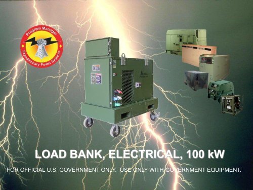
LOAD BANK, ELECTRICAL, 100 kW<br />
FOR OFFICIAL U.S. GOVERNMENT ONLY. USE ONLY WITH GOVERNMENT EQUIPMENT.
TABLE OF CONTENTS<br />
Points of Contact 1 Indicator LED Lamps 12<br />
Introduction 2 Power Controls 13<br />
Description 3 Blower Motor Controls 14<br />
Equipment Data 4 Load Control Switches 15,16<br />
General Safety Precautions 5 Operation in Unusual Conditions 17<br />
Grounding 6 Setup/Installation 18-22<br />
Interconnect Cable B31396<br />
21kW to 100kW 7 Before Operation 23-25<br />
Interconnect Cable B31397<br />
5kW to 30kW 8 Internal Power Operation 50/60 Hz 27-32<br />
Interconnect Cable B31398<br />
Ground 9 External Power Operations 400 Hz 33-36<br />
External Power Cord (400Hz) 10 During Operation 37,38<br />
Controls and Indicators<br />
Multifunction LED Display 11 Shutdown 39
POINTS OF CONTACT<br />
PM EPS FIELD SERVICE REPRESENTATIVES<br />
I MEF CAMP PENDLETON<br />
Mr. Talmadge Jackson<br />
talmadge.d.jackson.ctr@usmc.mil<br />
(951) 491-3556<br />
III MEF CAMP KINSER/FOSTER<br />
Mr. John O’Brien<br />
john.o’brien.ctr@usmc.mil<br />
011-81-611-745-7284 (DSN 645-7284)<br />
II MEF CAMP LEJEUNE<br />
Mr. Ken Copeland<br />
ken.copeland@usmc.mil<br />
(910) 545-2547<br />
MARINE FORCES RESERVE LIAISON<br />
Mr. Daryl Wilson<br />
daryl.wilson@L-3com.com<br />
(703) 445-8162<br />
TRAINING FIELD SERVICE REPRESENTATIVE, CAMP LEJEUNE<br />
Mr. Frank Bass<br />
frank.bass@usmc.mil<br />
(910) 450-7007<br />
Send requests to<br />
PM EPS MCSC at:<br />
pm_eps@nmci.usmc.mil<br />
1
INTRODUCTION<br />
This Job Aid provides basic operating instructions for the Load Bank,<br />
Electrical, 100kW. It includes a description and procedures to<br />
employ the Load Bank.<br />
Use this Job Aid as a quick reference guide to assist you<br />
in operating the Load Bank or training other personnel in its use.<br />
NOTICE TO USER<br />
This Job Aid does not replace the Operations/Maintenance Technical<br />
Manual (TM 07500C-OI). Refer to the technical manual for additional<br />
operating, troubleshooting procedures,<br />
maintenance instructions and safety precautions.<br />
2
DESCRIPTION<br />
The Avtron Model LSH100D42423 Load Bank is an<br />
outdoor unit designed to apply a balanced 3-phase<br />
resistive load, at 120/208 or 240/416 VAC at 50, 60 or<br />
400 Hz.<br />
The total load capability is 100kW and load steps are 1,<br />
2, 2, 5, 5, 10, 25, and 50kW. Any combination of load<br />
steps may be selected to achieve a desired load.<br />
The Load Bank contains a blower with a single-phase<br />
Blower Motor requiring 120/240 VAC, 50/60 Hz to<br />
provide the necessary cooling air for the resistive<br />
elements.<br />
3
EQUIPMENT DATA<br />
NSN…………………..6150-01-557-1304<br />
ID Number…………...07500C<br />
TAMCN……………….B0579<br />
Model Number………. LSH100D42423-1 (GREEN)<br />
LSH100D42423-2 (TAN)<br />
The Load Bank has two different model numbers to identify the different colors. The<br />
tan systems were ordered for the operating forces and the green / tan for MPS. If a<br />
unit increases their TE allowance, they will receive a tan model.<br />
4
GENERAL SAFETY PRECAUTIONS<br />
KEEP AWAY FROM LIVE CIRCUITS<br />
Operating personnel must at all times observe all safety regulations. Do not<br />
replace components or make adjustments inside the equipment with the<br />
voltage supply turned on. Under certain conditions, dangerous potentials may<br />
exist when the power control is in the OFF position. To avoid casualties,<br />
always remove power and discharge.<br />
GROUND A CIRCUIT BEFORE TOUCHING IT.<br />
DO NOT SERVICE OR ADJUST ALONE.<br />
Under no circumstances should any person reach into or enter the enclosure<br />
for the purpose of servicing or adjusting the equipment except in the presence<br />
of someone who is capable of rendering aid.<br />
RESUSCITATION<br />
Personnel working with or near high voltages should be familiar with modern<br />
methods of resuscitation. Such information may be obtained from the Bureau<br />
of Medicine and Surgery.<br />
5
GROUNDING<br />
Securely ground the Load Bank with either<br />
a ground rod or an established ground.<br />
The Load Bank and the Generator under<br />
test are to share the same physical earth<br />
ground point. Connect the Load Bank and<br />
the Generator to the same ground rod.<br />
Load Bank Ground wire<br />
Generator Ground wire<br />
6
COMPONENTS<br />
Interconnect Cable Set PN B31396, NSN 6152-01-570-4708, is<br />
to be used when connecting PHASE conductors for testing<br />
21kW to 100kW Generators (454 amp maximum). The size of<br />
these cables are 4/O AWG.<br />
Black Red Blue White<br />
7
COMPONENTS<br />
Interconnect Cable Set PN B31397, NSN 6150-01-570-3818, is to be<br />
used when connecting PHASE conductors for testing 5kW to 30kW<br />
Generators (118 amp maximum). The size of these cables are 6 AWG.<br />
Black Red Blue White<br />
8
COMPONENTS<br />
Interconnect Cable Ground PN B31398, NSN 6145-01-570-9583,<br />
is to be used to connect the Load Bank enclosure to the<br />
Generator ground rod kit. The size of this cable is 2 AWG.<br />
Green<br />
9
COMPONENTS<br />
A 25 foot external power cord is installed on<br />
the Load Bank. The external power cord<br />
connects to a 20 amp, 50/60 Hz, 120 VAC<br />
power supply to power the Load Bank control<br />
and blower circuits for testing 400 Hz<br />
Generators.<br />
10
CONTROLS AND INDICATORS<br />
DESIGNATOR CONTROL / INSTRUMENT PURPOSE / USE<br />
M1 Multifunction LED Display Displays levels of Voltage, Current, kW etc.<br />
11
CONTROLS AND INDICATORS<br />
DS1 DS2 DS3 DS4 DS5 DS6<br />
DESIGNATOR CONTROL / INSTRUMENT PURPOSE / USE<br />
DS1 Control Power Lamp Lamp Control Power, Green<br />
DS2 Air Failure Lamp Lamp Air Failure, Red<br />
DS3 Blower Power Lamp Lamp Blower Power, Amber<br />
DS4 Phase “A “ Indicator Lamp Lamp Phase A Input, Green<br />
DS5 Phase “B” Indicator Lamp Lamp Phase B Input, Green<br />
DS6 Phase “C” Indicator Lamp Lamp Phase C Input, Green<br />
12
CONTROLS AND INDICATORS<br />
S100<br />
DESIGNATOR CONTROL / INSTRUMENT PURPOSE / USE<br />
S18 Control Power Select Switch Selects an Internal or External source of control<br />
power<br />
S19<br />
External Control Power On / Off<br />
Switch<br />
Turns the External power On / Off<br />
S100 Internal Transformer “ON” Switch Energizes the Internal Transformer<br />
S101 Internal Transformer “OFF” Switch De-energizes the Internal Transformer<br />
S102<br />
S18 S19 S101 S102<br />
Internal Transformer Voltage<br />
Configuration Switch<br />
Selects the Internal Transformer Voltage<br />
Configuration<br />
13
CONTROLS AND INDICATORS<br />
S22 S23 S17<br />
DESIGNATOR CONTROL / INSTRUMENT PURPOSE / USE<br />
S22 Blower Start Switch (Black) Energizes the blower circuits<br />
S23 Blower Stop Switch (Red) De-energizes the blower circuits<br />
S17 Blower Voltage Select Switch Set to match the Generator voltage<br />
configuration or external power<br />
14
CONTROLS AND INDICATORS<br />
S21 S20 S1 S2 S3 S4<br />
DESIGNATOR CONTROL / INSTRUMENT PURPOSE / USE<br />
S21 Load Voltage Select Switch Set to match the Generator voltage configuration<br />
S20 Master Load Switch Activates and controls load step switches<br />
S1 1 kW Toggle Switch Applies 1kW load to phase A, B and C<br />
S2 2 kW Toggle Switch Applies 2kW load to phase A, B and C<br />
S3 2 kW Toggle Switch Applies 2kW load to phase A, B and C<br />
S4 5 kW Toggle Switch Applies 5kW load to phase A, B and C<br />
15
CONTROLS AND INDICATORS<br />
S5 S6 S7 S8<br />
DESIGNATOR CONTROL / INSTRUMENT PURPOSE / USE<br />
S5 5 kW Toggle Switch Applies 5kW load to phase A, B and C<br />
S6 10 kW Toggle Switch Applies 10kW load to phase A, B and C<br />
S7 25 kW Toggle Switch Applies 25kW load to phase A, B and C<br />
S8 50 kW Toggle Switch Applies 50kW load to phase A, B and C<br />
16
OPERATION IN UNUSUAL<br />
CONDITIONS<br />
1. The Load Bank is designed to operate in ambient temperatures between -25 F and<br />
131 F.<br />
2. The Load Bank will operate satisfactorily after storage in ambient temperatures<br />
between -40 F and 160 F.<br />
3. The Load Bank must be allowed to acclimate to within its rated ambient<br />
temperature range of -25 F and 131 F prior to operation.<br />
4. After periods of storage in cold environments below -25 F, the Load Bank control<br />
circuitry must be energized for a minimum of 15 minutes prior to operation, to<br />
warm the control circuitry.<br />
5. When operating the Load Bank in windy conditions, position the Load Bank so the<br />
exhaust does not blow against the prevailing wind.<br />
6. When operating the Load Bank above 4,000 feet, refer to the applicable Generator<br />
TM for the Generator derate percentage.<br />
17
SETUP AND INSTALLATION<br />
Step 1. Provide adequate ventilation and unrestricted air flow around units. Minimum of<br />
six feet intake and fifteen feet exhaust.<br />
Step 2. Ensure that the air intake and exhaust areas are not blocked.<br />
Step 3. Ensure the rear wheel casters are locked.<br />
Step 4. Securely ground the Load Bank to an established ground. The Load Bank and<br />
the Generator are to share the same physical earth ground point.<br />
Load Bank Ground wire<br />
Generator Ground wire<br />
18
SETUP/INSTALLATION<br />
6 Ft.<br />
Min. Intake Clearance<br />
6 Ft.<br />
Min. Intake Clearance<br />
15 Ft.<br />
Min. Exhaust Clearance<br />
Lock<br />
Casters<br />
19
SETUP/INSTALLATION<br />
Step 5. Place the EXT 120V, Master Load, and all Load Step Switches to the OFF<br />
position.<br />
OFF<br />
Step 6. Connect the Generator to be tested to the Load Bank.<br />
20
SETUP/INSTALLATION<br />
WARNING<br />
BE SURE THAT THE GENERATOR IS DE-ENERGIZED BEFORE<br />
CONNECTIONS ARE MADE AND USE INTERCONNECTING CABLE<br />
ADEQUATELY RATED FOR THE LOAD.<br />
Step 7. Connect the Cam Lock connectors according to the following table and<br />
the illustrations on page 22 and 23.<br />
GENERATOR<br />
LOAD BANK<br />
L1 or Phase A PH A Black<br />
L2 or Phase B PH B Red<br />
L3 or Phase C PH C Blue<br />
L0 or Neutral N White<br />
Ground Ground Green<br />
Step 8. Ensure the Cam Lock connectors are fully secured to the Load Bank.<br />
They must be rotated 180° clockwise to lock. Locked correctly, the<br />
connector sleeve set screws will be at the 6 o’clock position.<br />
21
SETUP/INSTALLATION<br />
A B C<br />
WARNING<br />
DO NOT USE CABLING WITH LOOSE OR FRAYED STRANDS.<br />
22
BEFORE OPERATION<br />
Step 1. Inspect the Load Bank set for any internal or external damage.<br />
Step 2. Open the connection box enclosure door. Inspect all cables and wires for<br />
damage, looseness or corrosion.<br />
Step 3. Verify all fuses and relays are installed.<br />
Step 4. Close CB1.<br />
CB1<br />
23
BEFORE OPERATION<br />
Step 5. Close and secure the connection box enclosure door.<br />
Step 6. Check the control panel for damage.<br />
Step 7. Check air intake and exhaust grills for any obstructions.<br />
Step 8. Inspect input cables for defective insulation and secure connections.<br />
Cable Set B31396, 454 AMPS<br />
Cable Set B31397, 118 AMPS<br />
24
BEFORE OPERATION<br />
Step 9. Ensure that cables are correctly connected to the Generator.<br />
Step 10. Ensure that you understand the current rating of the Generator<br />
under test and the correct interconnect cable set is connected.<br />
Refer to the Generator’s Technical Manual.<br />
Step 11. If testing a 400 Hz Generator, plug in the External Power Cord.<br />
The External Power Cord must be used to<br />
power the control and blower circuits.<br />
NOTE<br />
The External Power Cord must be plugged into<br />
a source capable of providing 20 amps 120 VAC<br />
50/60 Hz.<br />
External Power Cord<br />
25
120/208VAC 50/60 Hz<br />
INTERNAL POWER OPERATION<br />
Step 1. Place the CONTROL POWER SELECT Switch to the INTERNAL position.<br />
Step 2. Set the INT XFRMR Switch to 120/208V position.<br />
Step 3. Place the BLOWER VOLTAGE SELECT switch to the INT 208 position.<br />
Step 4. Start the Generator under test and allow the Generator to reach operational<br />
temperature, then close the Generator Load Contactor. Load Bank indicator<br />
LEDS (DS4 - DS6) PHASE A, PHASE B, PHASE C will illuminate.<br />
Step 5. Press the CONTROL POWER ON pushbutton. Indicator LED (DS1) CONTROL<br />
POWER and M1 Digital Meter will illuminate.<br />
Step 6. Allow the Digital Meter to run a self test.<br />
27
120/208VAC 50/60 Hz<br />
INTERNAL POWER OPERATION<br />
Step 7. Press the BLOWER POWER START pushbutton switch. The BLOWER<br />
POWER LED (DS3) will illuminate.<br />
NOTE<br />
The AIR FAILURE LED (DS2) will flash on momentarily.<br />
CAUTION<br />
The operation of the blower is vital to the safe operation of this Load Bank. When<br />
the blower is turned ON, the AIR FAILURE LED will come on momentarily until the<br />
blower accelerates up to its operating speed, at which time the LED will go off. If<br />
the air switch prevents the load from being applied (AIR FAILURE indicator LED<br />
on), do not bypass the air switch. This will cause the Load Bank to burn up. Do not<br />
attempt to operate the unit until the problem is corrected. Refer to operators<br />
troubleshooting procedures in Table 3-4, for Air Failure LED.<br />
28
120/208VAC 50/60 Hz<br />
INTERNAL POWER OPERATION<br />
Step 8. Place the LOAD VOLTAGE SELECT Switch in the 120/208 position.<br />
Step 9. Place the MASTER LOAD switch to the ON position.<br />
Step 10. Use the up or down arrow keys to set the Digital Meter to display<br />
current on each phase.<br />
Step 11. Using the LOAD STEP toggle switches, turn on one toggle switch at a time<br />
until the desired load for testing has been obtained.<br />
CAUTION<br />
Observe the Digital Meter to ensure you do not exceed the current rating of<br />
the Generator under test or the interconnect cable set. Failure to observe<br />
this caution may cause damage to the equipment.<br />
29
240/416VAC 50/60 Hz<br />
INTERNAL POWER OPERATION<br />
Step 1. Place the CONTROL POWER SELECT Switch to the INTERNAL position.<br />
Step 2. Set the INT XFRMR Switch to 240/416V position.<br />
Step 3. Place the BLOWER VOLTAGE SELECT switch to the INT 416 position.<br />
Step 4. Start the Generator under test, and allow the Generator to reach operational<br />
temperature, close the Generator Load Contactor. Indicator LEDS (DS4-DS6)<br />
PHASE A, PHASE B, PHASE C will illuminate.<br />
Step 5. Press the CONTROL POWER ON pushbutton. Indicator LED (DS1) CONTROL<br />
POWER and M1 Digital Meter will illuminate.<br />
Step 6. Allow the Digital Meter to run a self test.<br />
30
240/416VAC 50/60 Hz<br />
INTERNAL POWER OPERATION<br />
Step 7. Press the BLOWER POWER START pushbutton switch. The BLOWER<br />
POWER LED (DS3) will illuminate.<br />
NOTE<br />
The AIR FAILURE LED (DS2) will flash on momentarily.<br />
CAUTION<br />
The operation of the blower is vital to the safe operation of this Load Bank. When<br />
the blower is turned ON, the AIR FAILURE LED will come on momentarily until the<br />
blower accelerates up to its operating speed, at which time the LED will go off. If<br />
the air switch prevents the load from being applied (AIR FAILURE indicator LED<br />
on), do not bypass the air switch. This will cause the Load Bank to burn up. Do<br />
not attempt to operate the unit until the problem is corrected. Refer to operators<br />
troubleshooting procedures in Table 3-4, for Air Failure LED.<br />
31
240/416VAC 50/60 Hz<br />
INTERNAL POWER OPERATION<br />
Step 8. Place the LOAD VOLTAGE SELECT Switch in the 240/416 position.<br />
Step 9. Place the MASTER LOAD switch to the ON position.<br />
Step 10. Use the up or down arrow keys to set the Digital Meter to display<br />
current on each phase.<br />
Step 11. Using the LOAD STEP toggle switches, turn on one toggle switch at a<br />
time until the desired load for testing has been obtained.<br />
CAUTION<br />
Observe the Digital Meter to ensure you do not exceed the current rating<br />
of the Generator under test or the interconnect cable set. Failure to<br />
observe this caution may cause damage to the equipment.<br />
32
120/208VAC, 240/416VAC<br />
400 Hz EXTERNAL POWER OPERATION<br />
CAUTION<br />
DO NOT operate the Load Bank from the Generator INTERNAL voltage<br />
source when testing Generators at 400 Hz. For 400 Hz testing, CONTROL<br />
and BLOWER POWER must be EXTERNAL. Use the External Power Cord<br />
provided with the Load Bank.<br />
NOTE<br />
The External Power Cord must be plugged into a source capable of providing<br />
20 Amps 120 VAC 50/60 Hz.<br />
33
120/208VAC, 240/416VAC<br />
400 Hz EXTERNAL POWER OPERATION<br />
Step 1. Place the CONTROL POWER SELECT Switch to the EXTERNAL position.<br />
Step 2. Place the BLOWER VOLTAGE SELECT switch to the EXT 120 position.<br />
Step 3. Start the Generator under test, allow the Generator to reach operational<br />
temperature, close the Generator Load Contactor. Load Bank indicator LEDS<br />
(DS4-DS6) PHASE A, PHASE B, PHASE C will illuminate.<br />
Step 4. Set the CONTROL POWER Switch EXT 120V to the ON position.<br />
Indicator LED (DS1) CONTROL POWER and M1 Digital Meter will illuminate.<br />
Step 5. Allow the Digital Meter to run a self test.<br />
34
120/208VAC, 240/416VAC<br />
400 Hz EXTERNAL POWER OPERATION<br />
Step 6. Press the BLOWER POWER START pushbutton switch. The BLOWER<br />
POWER LED (DS3) will illuminate.<br />
NOTE<br />
The AIR FAILURE LED (DS2) will flash on momentarily.<br />
CAUTION<br />
The operation of the blower is vital to the safe operation of this Load Bank. When<br />
the blower is turned ON, the AIR FAILURE LED will come on momentarily until the<br />
blower accelerates up to its operating speed, at which time the LED will go off. If<br />
the air switch prevents the load from being applied (AIR FAILURE indicator LED<br />
on), do not bypass the air switch. This will cause the Load Bank to burn up. Do<br />
not attempt to operate the unit until the problem is corrected. Refer to operators<br />
troubleshooting procedures in Table 3-4, for Air Failure LED.<br />
35
120/208VAC, 240/416VAC<br />
400 Hz EXTERNAL POWER OPERATION<br />
Step 7. Place the LOAD VOLTAGE SELECT Switch in the 120/208 or 240/416<br />
position.<br />
Step 8. Place the MASTER LOAD switch to the ON position.<br />
Step 9. Use the up or down arrow keys to set the Digital Meter to display<br />
current on each phase.<br />
Step 10. Using the LOAD STEP toggle switches, turn on one toggle switch at a<br />
time until the desired load for testing has been obtained.<br />
CAUTION<br />
Observe the Digital Meter to ensure you do not exceed the current rating of<br />
the Generator under test or the interconnect cable set. Failure to observe<br />
this caution may cause damage to the equipment.<br />
36
DURING OPERATION<br />
WARNING<br />
DO NOT TOUCH THE EXHAUST SCREEN DURING OPERATION. THE<br />
SCREEN WILL BECOME HOT FROM THE EXHAUSTED HEAT AND MAY<br />
CAUSE A SERIOUS BURN. DO NOT ALLOW OBJECTS TO ENTER OR<br />
BLOCK THE AIR INTAKE SCREENS.<br />
WARNING<br />
DO NOT OPEN THE CONNECTION BOX ENCLOSURE DOOR DURING<br />
OPERATION. LETHAL VOLTAGES ARE PRESENT. FAILURE TO<br />
OBSERVE THIS WARNING MAY RESULT IN INJURY OR DEATH BY<br />
ELECTROCUTION.<br />
37
DURING OPERATION<br />
Step 1. Monitor both the Digital Display Meter and the Generator under test control<br />
panel to ensure all indicators remain within operational range. Refer to the<br />
applicable Generator’s Technical Manual.<br />
Load Bank Digital Display<br />
TQG Alpha Series<br />
TQG Bravo Series<br />
MEP 807A<br />
38
SHUTDOWN<br />
Step 1. Decrease the applied load by turning the load step switches off one at a<br />
time.<br />
Step 2. Turn the MASTER LOAD SWITCH off.<br />
Step 3. Allow the blower to run for five minutes to cool the resistive elements.<br />
Step 4. Press the blower power STOP pushbutton switch.<br />
Step 5. Press the CONTROL POWER OFF pushbutton or place the<br />
EXTERNAL CONTROL POWER switch to the OFF position.<br />
Step 6. Open the Generator Load Contactor.<br />
Step 7. Allow the Generator to run for five minutes to cool the engine and<br />
A/C alternator.<br />
Step 8. Shutdown the Generator, refer to the applicable Generator’s Technical<br />
Manual.<br />
39
VISIT THE PM EPS WEB SITE<br />
www. marcorsyscom.usmc .mil/sites/pmeps<br />
or send inquiries to<br />
pm_eps@nmci.usmc.mil<br />
Published by the Program Manager, Expeditionary<br />
Power <strong>Systems</strong>, <strong>Marine</strong> <strong>Corps</strong> <strong>Systems</strong> <strong>Command</strong> on<br />
30 July 2010