BCA 2010 - ABCB - Australian Building Codes Board
BCA 2010 - ABCB - Australian Building Codes Board
BCA 2010 - ABCB - Australian Building Codes Board

You also want an ePaper? Increase the reach of your titles
YUMPU automatically turns print PDFs into web optimized ePapers that Google loves.
Client Feature<br />
BRANZ: Installed performance of ceiling insulation<br />
BRANZ recently compared the in situ<br />
performance of ceiling insulation<br />
installed in the more traditional layout of<br />
friction-fitting between ceiling framing,<br />
with the same insulation installed<br />
over the top of framing (without any<br />
insulation between the framing).<br />
Led by Ian Cox-Smith, BRANZ <strong>Building</strong><br />
Physicist, the recent BRANZ research<br />
project looked at what gives the best<br />
performance.<br />
Figure 1: Polyester insulation fitted against<br />
framing in the way the R-value has traditionally<br />
been calculated.<br />
Figure 2: Thermal resistance improves when<br />
insulation is cut to the width of the space<br />
between framing plus twice the width of the<br />
frame (2 × 45 mm).<br />
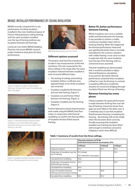
BRANZ <strong>Building</strong> Physicist Ian Cox-Smith<br />
Different options assessed<br />
The project used heat flux transducers<br />
to take in situ measurements of thermal<br />
resistance. This was measured for the<br />
three ceilings in the study after the same<br />
insulation material had been installed in<br />
each of several different ways:<br />
• The testing of ceilings and existing<br />
insulation before a sufficient area<br />
(approximately 4 m2) of the insulation<br />
was removed.<br />
• Insulation installed both between<br />
and over the framing. (Figure 1)<br />
• Insulation cut and friction-fitted<br />
between the framing. (Figure 2)<br />
• Insulation installed over the framing.<br />
(Figure 3)<br />
Further laboratory-based measurements<br />
were made using the BRANZ heat flow<br />
meter, in conjunction with thermal<br />
modelling, to confirm the thermal effect<br />
of insulation friction-fitted around<br />
framing.<br />
Better fit, better performance<br />
between framing<br />
Where insulation was cut to a suitable<br />
width and fitted between the framing,<br />
it was possible to achieve a visibly<br />
continuous insulation layer with no<br />
framing showing. When this happened,<br />
the thermal performance measured<br />
was significantly better than is normally<br />
calculated for the common situation<br />
with visible framing. It was close to what<br />
is expected with the same insulation<br />
over the top of the framing, with no<br />
convective losses assumed.<br />
Thermal modelling has demonstated<br />
that it would be possible to adjust<br />
Thermal Resistance calculations<br />
to account for the better thermal<br />
performance achieved when insulation<br />
is fitted to cover the framing. In contrast,<br />
it would be difficult to model the<br />
situation of convective bridging through<br />
insulation fitted over the top of framing.<br />
Between framing has many<br />
pluses<br />
Fitting insulation for good performance<br />
is easier between framing than over the<br />
top of framing. Convective losses from<br />
gaps are more likely in the latter case. It<br />
is relatively easy to see that insulation<br />
fitted between framing is insulating the<br />
framing – the framing will not be visible<br />
when this has been done correctly.<br />
Visually assessing that insulation<br />
installed over framing has been fitted<br />
well enough to minimise convective<br />
bridging is much more difficult.<br />
<strong>BCA</strong> PRODUCT + iNDUSTRY INNOVATION NEWS<br />
Table 1: Summary of results from the three ceilings.<br />
Figure 3: Installing insulation between and over<br />
the top of framing gives the best R-values.<br />
Thermal resistance (m²K/W)<br />
Estimated measurement (uncertainty 10%)<br />
Ceiling A Ceiling B Ceiling C<br />
Original insulation R1.5 R1.7 R2.2<br />
Single layer of insulation over the<br />
top of framing<br />
Calculated from modelling R3.6<br />
Single layer of insulation frictionfitted<br />
between framing<br />
Calculated from modelling R3.6<br />
Layer of insulation between<br />
framing and second layer framing<br />
R1.5 (initial)<br />
R3.5 (refitted to close gaps)<br />
R1.5<br />
R3.5 R3.7<br />
>R5 R4.8<br />
Calculated from modelling R6.5 R5.2<br />
<strong>Australian</strong> <strong>Building</strong> Regulation Bulletin<br />
• 39