- Page 1 and 2: Laser printer SERVICE MANUAL Publis
- Page 3 and 4: Safety precautions This booklet pro
- Page 5 and 6: 1. Installation Precautions WARNING
- Page 7 and 8: • Do not pull on the AC power cor
- Page 9 and 10: Chapter 1 Product Information
- Page 11 and 12: 1-1 Printer specifications 1-1-1 Sp
- Page 13 and 14: (4) Power requirements Item Voltage
- Page 15 and 16: (2) Memory card (CompactFlash) The
- Page 17 and 18: 1-2 Names of parts 1-2-1 Names of p
- Page 19 and 20: (2) Ozone concentration The printer
- Page 21 and 22: 1-4 Environmental requirements 1-4-
- Page 23 and 24: (2) Places to avoid Avoid installin
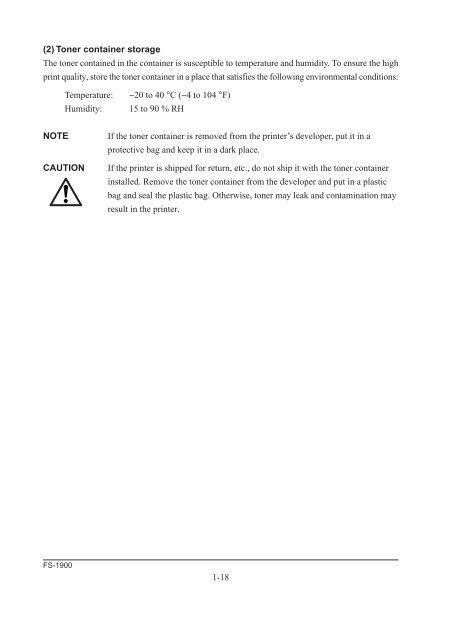
- Page 25: 1-5 About the toner container 1-5-1
- Page 29 and 30: 2-1 Unpacking 2-1-1 Unpacking and i
- Page 31 and 32: 2-2 Installing the printer Installi
- Page 33 and 34: Removing the toner container To rem
- Page 35 and 36: Removing the waste toner box To rem
- Page 37 and 38: (3) Notes on handling DIMM Before p
- Page 39 and 40: 5. Open the clips 4 on both ends of
- Page 41 and 42: (7) Installing the option memory ca
- Page 43 and 44: (9) Installing the option serial in
- Page 45 and 46: Key 4 GO key 5 CANCEL key 6 MENU ke
- Page 47 and 48: (4) Paper type Indicator The TYPE i
- Page 49 and 50: 2-3-2 Menu selection system The MEN
- Page 51 and 52: Print Quality > Memory Card > >KIR
- Page 53 and 54: Chapter 3 Maintenance/Adjustments
- Page 55 and 56: 3-1 Maintenance/Adjustments 3-1-1 L
- Page 57 and 58: (3) Toner container replacement To
- Page 59 and 60: (5) Replacing the waste toner box N
- Page 61 and 62: (2) Cleaning the main charger wire
- Page 63 and 64: 3. After attaching the grid cleaner
- Page 65 and 66: (4) Replacing the developer To remo
- Page 67 and 68: (6) Developer refreshing mode This
- Page 69 and 70: 3-1-4 Updating the firmware Updatin
- Page 71 and 72: (2) Downloading the firmware from t
- Page 73 and 74: (3) Downloading the firmware from t
- Page 75 and 76: (4) Downloading errors The followin
- Page 77 and 78:
Chapter 4 Contents 4-1 Electrophoto
- Page 79 and 80:
(1) Main charging Components of dru
- Page 81 and 82:
Charging the drum The following sho
- Page 83 and 84:
Laser scanner unit 4 5 3 2 9 1 6 0
- Page 85 and 86:
Drum surface potential The laser be
- Page 87 and 88:
The latent image constituted on the
- Page 89 and 90:
(4) Transfer The image developed by
- Page 91 and 92:
Fuser unit mechanism 1 To face-down
- Page 93 and 94:
4-2 Paper feeding system The paper
- Page 95 and 96:
(1) Paper feeding mechanism Drive a
- Page 97 and 98:
Fuser unit and face up/down output
- Page 99 and 100:
(2) Motors, solenoids, clutches and
- Page 101 and 102:
4-3-2 Operation of circuit boards (
- Page 103 and 104:
Eraser lamp control circuit CPU (U2
- Page 105 and 106:
Heater lamp control circuit The hea
- Page 107 and 108:
(3) Sensor board Paper gauge sensin
- Page 109 and 110:
The interlock circuit outputs the t
- Page 111 and 112:
The paper size dial has predetermin
- Page 113 and 114:
(5) High voltage unit High voltage
- Page 115 and 116:
Chapter 5 Contents 5-1 General inst
- Page 117 and 118:
5-2 Disassembly 5-2-1 Removing the
- Page 119 and 120:
5-2-2 Removing the paper transfer u
- Page 121 and 122:
5-2-4 Removing the operator panel a
- Page 123 and 124:
(3) Removing the right cover 1. Rem
- Page 125 and 126:
5-2-5 Removing the drum unit 1. Rem
- Page 127 and 128:
5. Remove the feed bracket cover 4
- Page 129 and 130:
5. Pull the MP tray paper feed unit
- Page 131 and 132:
5-2-9 Removing the controller unit
- Page 133 and 134:
5. Remove three screws 4. 6. Remove
- Page 135 and 136:
(2) Removing the engine board and p
- Page 137 and 138:
(3) Removing the main board CAUTION
- Page 139 and 140:
(5) Removing the sensor board CAUTI
- Page 141 and 142:
8. Remove four screws 6. 9. Remove
- Page 143 and 144:
4. Remove the rear cover 4 and the
- Page 145 and 146:
(1) Removing the separators WARNING
- Page 147 and 148:
(3) Removing the heat roller WARNIN
- Page 149 and 150:
(5) Removing the press roller WARNI
- Page 151 and 152:
Chapter 6 T roubleshooting
- Page 153 and 154:
6-1-4 Circuit board terminal voltag
- Page 155 and 156:
Message Corrective action Load Cass
- Page 157 and 158:
(2) Error messages Message Correcti
- Page 159 and 160:
Message Corrective action Memory ov
- Page 161 and 162:
6-1-2 Diagnostic (Service error mes
- Page 163 and 164:
(5) 2000 - Main motor error Meaning
- Page 165 and 166:
(10) 4000 - Laser scanner unit (Pol
- Page 167 and 168:
(12) 5300 - Eraser lamp error Meani
- Page 169 and 170:
(14) 6020 - Abnormal high temperatu
- Page 171 and 172:
(17) 7350 - Toner refreshing mode e
- Page 173 and 174:
6-1-3 Other problems (1) False “C
- Page 175 and 176:
(5) Defective paper jam detecting P
- Page 177 and 178:
(9) Defective face up/down solenoid
- Page 179 and 180:
Connector Pin# Signal I/O Voltage F
- Page 181 and 182:
Connector Pin# Signal I/O Voltage F
- Page 183 and 184:
Connector Pin# Signal I/O Voltage F
- Page 185 and 186:
6-1-6 Print quality problems Print
- Page 187 and 188:
(2) All-black printout Check the ma
- Page 189 and 190:
(4) Black dots ABC 123 Note the spa
- Page 191 and 192:
(7) Unsharpness Check paper for pro
- Page 193 and 194:
(9) Dirt on the top edge or back of
- Page 195 and 196:
Repetitive defects gauge Use the fo
- Page 197 and 198:
(2) Jam inside the printer 1. While
- Page 199 and 200:
Appendix A Contents Timing charts..
- Page 201 and 202:
Cassette feeding, two letter size p
- Page 203 and 204:
Option paper feeder cassette feedin
- Page 205 and 206:
MP tray feeding, two letter size pa
- Page 207 and 208:
A-10 FS-1900 + − 1 3 1 2 1 2 1 2
- Page 209 and 210:
Appendix B Contents Status page ...
- Page 211 and 212:
Service information on the status p
- Page 213 and 214:
Example Meaning Description 7 P00/
- Page 215 and 216:
Appendix C I n t e r f a c e
- Page 217 and 218:
Parallel interface The printer uses
- Page 219 and 220:
Parallel interface signals The foll
- Page 221 and 222:
Serial interface (option) This prin
- Page 223 and 224:
KYOCERA MITA EUROPE B.V. Hoeksteen