Testing and quality
Testing and quality
Testing and quality

You also want an ePaper? Increase the reach of your titles
YUMPU automatically turns print PDFs into web optimized ePapers that Google loves.
1/2011<br />
Proven <strong>quality</strong><br />
Innovation<br />
through testing<br />
Advanced measuring<br />
Development of<br />
plastic products<br />
Prevention of outage<br />
Monitoring of motors<br />
<strong>and</strong> generators<br />
<strong>Testing</strong> <strong>and</strong> <strong>quality</strong>
EDITORIAL<br />
Test procedures for the development<br />
of high-<strong>quality</strong> products<br />
Dear Technology Professionals, Customers, <strong>and</strong> Partners,<br />
Continuous innovation <strong>and</strong> product improvements are often supported by<br />
sophisticated, state-of-the-art test <strong>and</strong> measurement methods. The articles of the<br />
current issue of the Sulzer Technical Review (STR) will present test equipment,<br />
measuring methods, <strong>and</strong> specific competencies of the Sulzer divisions that are crucial<br />
for research <strong>and</strong> development, for <strong>quality</strong> assessments, <strong>and</strong> for the improvement<br />
of our products.<br />
Sulzer Pumps operates test facilities around the globe. Learn more about the<br />
world's largest string testing facility in Leeds (UK), as well as our expertise <strong>and</strong> test<br />
facilities in Suzhou (CN), Kotka (FIN), <strong>and</strong> Winterthur (CH).<br />
Modern development <strong>and</strong> production facilities <strong>and</strong> globally coordinated teams<br />
allow Sulzer Metco to produce new application-tailored coating materials. Learn more<br />
about our new pilot plant in Troy (MI, USA), which can efficiently produce test<br />
powders in amounts of 5 to 100 kilograms.<br />
In the article from Sulzer Chemtech, you will learn more about the importance of<br />
modern analysis during the production <strong>and</strong> processing of plastics. Sulzer Turbo<br />
Services uses a variety of monitoring methods to assess the status of motors <strong>and</strong><br />
generators during operation. This measurement technique protects the customers<br />
from long downtimes <strong>and</strong> production losses. Sulzer Innotec’s engineering, testing<br />
<strong>and</strong> interpretation skills have allowed for new ways of analysis <strong>and</strong> evaluation of<br />
pump impeller measurements.<br />
In the other contributions, you will learn more about our solutions for energy<br />
recovery, our research capabilities, <strong>and</strong> our services for repairing motors <strong>and</strong><br />
generators.<br />
I hope you enjoy this issue.<br />
Sincerely yours,<br />
Ton Büchner<br />
CEO Sulzer<br />
2 | Sulzer Technical Review 1/2011<br />
Sulzer today<br />
The Sulzer brothers laid the foundations of<br />
today's company in 1834 in Winterthur,<br />
Switzerl<strong>and</strong>. Sulzer is active in the fields of<br />
machinery, equipment manufacturing, <strong>and</strong><br />
surface technology in more than 160 locations<br />
around the world. Its divisions are global<br />
leaders in their respec tive markets, including<br />
the oil <strong>and</strong> gas sector, the hydrocarbon<br />
processing industry, power generation, pulp<br />
<strong>and</strong> paper, aviation, <strong>and</strong> the automotive<br />
industry. Sulzer employs more than 13 000<br />
professionals who develop innovative new<br />
technical solutions. These prod ucts <strong>and</strong> services<br />
enable Sulzer's customers to achieve sustained<br />
improvements in their competitive positions.<br />
www.sulzer.com<br />
Sulzer Pumps<br />
Sulzer Pumps offers a variety of centrifugal<br />
pumps, ranging from custom-built models to<br />
st<strong>and</strong>ardized series. The division's marketleading<br />
position reflects its research <strong>and</strong><br />
development activities relating to processoriented<br />
materials as well as its reliable service.<br />
It serves customers in the oil <strong>and</strong> gas, hydro -<br />
carbon processing, pulp <strong>and</strong> paper, power<br />
generation, water distribution <strong>and</strong> treatment<br />
sectors, as well as other specialized areas.<br />
www.sulzerpumps.com<br />
Sulzer Metco<br />
Sulzer Metco specializes in thermal-spray <strong>and</strong><br />
thin-film processes for surface technology<br />
applications. The division coats <strong>and</strong> enhances<br />
surfaces, produces materials <strong>and</strong> equipment,<br />
<strong>and</strong> develops machining processes for special<br />
components. Its customers are active in the<br />
aviation <strong>and</strong> automotive industries, the power<br />
generation segment, <strong>and</strong> other specialized<br />
markets.<br />
www.sulzermetco.com<br />
Sulzer Chemtech<br />
Sulzer Chemtech is the market leader in the<br />
fields of process tech nol ogy, separation<br />
columns, static mixing, <strong>and</strong> cartridge tech -<br />
nologies. The division has sales, engineering,<br />
production, <strong>and</strong> customer service facilities<br />
throughout the world that enable it to meet the<br />
needs of its customers in the oil <strong>and</strong> gas,<br />
chemical, petro chemical <strong>and</strong> plastics industries.<br />
www.sulzerchemtech.com<br />
Sulzer Turbo Services<br />
Sulzer Turbo Services is a leading independent<br />
provider of repair <strong>and</strong> maintenance services for<br />
turbomachinery, generators, <strong>and</strong> motors with<br />
expertise in rotating equipment. The division<br />
also manufactures <strong>and</strong> sells replacement parts<br />
for gas <strong>and</strong> steam turbines, compressors,<br />
generators, <strong>and</strong> motors. Sulzer Turbo Services’<br />
customers are located in the oil <strong>and</strong> gas, hydrocarbon<br />
processing, power generation, transport,<br />
mining, <strong>and</strong> other industrial markets.<br />
www.sulzerts.com<br />
Sulzer Innotec<br />
The research <strong>and</strong> development unit supports<br />
the development projects of Sulzer's own<br />
divisions as well as projects of industrial<br />
companies around the world by providing<br />
contract research <strong>and</strong> special technical services.<br />
Sulzer Innotec has considerable expertise in<br />
materials engineering, surface engineering,<br />
fluid technology, as well as in the field of<br />
mechanics. Its core competencies in the area of<br />
contract research also focus on these traditional<br />
disciplines.<br />
www.sulzerinnotec.com
<strong>Testing</strong> <strong>and</strong> <strong>quality</strong><br />
Panorama<br />
4 News<br />
Exhibitions, Events<br />
6 Proven <strong>quality</strong><br />
Innovation through testing—test facilities that support product development<br />
10 The key to application-tailored coating materials<br />
Driving development through an exp<strong>and</strong>ed “global-local” organization<br />
14 Filter <strong>and</strong> fit<br />
Revealing <strong>and</strong> interpreting hidden features using dedicated signal analysis<br />
17 Sulzer analogy<br />
<strong>Testing</strong> poisons<br />
18 A crucial factor in product development<br />
State-of-the-art measurement technology<br />
22 Prevention of outage major downtime<br />
Condition-based monitoring of motors <strong>and</strong> generators<br />
25 Sulzer innovation<br />
The ideal solution for corrosive media<br />
26 Reducing pressure—increasing efficiency<br />
When pressure has to be reduced in a process,<br />
using pumps as turbines increases<br />
the overall efficiency significantly<br />
30 Characterization of arbitrary distributions<br />
A new method<br />
33 Sulzer world<br />
Welcome to Sulzer Pumps in Suzhou<br />
34 Interview<br />
John Allen, Sulzer Dowding & Mills<br />
35 Imprint<br />
On the cover:<br />
The vibration responses of an impeller of a centrifugal compressor is measured without contact with a laser vibrometer.<br />
The post-processing of the measurement results uses a method developed by Sulzer Innotec that enables the determination<br />
of the natural frequencies <strong>and</strong> the mode shapes of the wheel—for <strong>quality</strong> control <strong>and</strong> for safe operation.<br />
CONTENTS<br />
Sulzer Technical Review 1/2011 |<br />
3
Exhibitions, Events<br />
April 7–9, 2011, Shanghai, China<br />
China International Engineering Expo & Symposium 2011<br />
www.seexpo.net<br />
Information for Sulzer Metco: Simon Xiao<br />
Phone +86 21 5226 4713<br />
simon.xiao@sulzer.com<br />
April 10–13, 2011, Rotorua, New Zeal<strong>and</strong><br />
APPITA 2011<br />
www.appita.com<br />
Information for Sulzer Pumps: Claudia Pröger<br />
Phone +41 52 262 39 04<br />
claudia.proeger@sulzer.com<br />
April 10–14, 2011, Palm Beach, FL, USA<br />
Spring CTOTF<br />
www.ctotf.org<br />
Information for Sulzer Turbo Services: Stephanie King<br />
Phone +1 713 567 2748<br />
stephanie.king@sulzer.com<br />
April 11–16, 2011, Beijing, China<br />
The 12th China International Machine Tool Show<br />
www.cimtshow.com<br />
Information for Sulzer Metco: Simon Xiao<br />
Phone +86 21 5226 4713<br />
simon.xiao@sulzer.com<br />
April 12–14, 2011, Rotterdam, The Netherl<strong>and</strong>s<br />
Ahoy Rotterdam<br />
www.maintenannext.nl<br />
Information for Sulzer Turbo Services:<br />
Elisabeth van den Houten<br />
Phone +31 181 282 088<br />
elisabeth.v<strong>and</strong>enHouten@sulzer.com<br />
May 2–6, 2011, San Diego, CA, USA<br />
ICMCTF 2011<br />
www2.avs.org<br />
Information for Sulzer Metco: Corinna Heinz<br />
Phone +49 2204 299 215<br />
corinna.heinz@sulzer.com<br />
May 2–5, 2011, Houston, TX, USA<br />
OTC 2011<br />
www.otcnet.org<br />
Information for Sulzer Pumps: Claudia Pröger<br />
Phone +41 52 262 39 04<br />
claudia.proeger@sulzer.com<br />
May 9–11, 2011, Adelaide, Australia<br />
Ozwater 2011<br />
www.ozwater11.com.au<br />
Information for Sulzer Pumps: Claudia Pröger<br />
Phone +41 52 262 39 04<br />
claudia.proeger@sulzer.com<br />
May 9–13, 2011, Houston, TX, USA<br />
GE 7FA Users Group Conference<br />
http://ge7fa.users-groups.com<br />
Information for Sulzer Turbo Services: Stephanie King<br />
Phone +1 713 567 2748<br />
stephanie.king@sulzer.com<br />
Geographical expansion, innovation,<br />
<strong>and</strong> selective acquisitions<br />
In 2010, Sulzer proved its ability to adapt<br />
quickly to changed market conditions.<br />
The company achieved a strong doubledigit<br />
profitability with a return on sales<br />
of 12.8% <strong>and</strong> an improved return on capital<br />
employed of 28.1%. Sales (CHF 3.2<br />
billion, –5.0%) were still impacted by the<br />
notable decrease in order intake in 2009.<br />
Net income increased by 11% to<br />
CHF 300.4 million, corresponding to<br />
earnings per share (EPS) of CHF 8.92.<br />
Sulzer’s global presence was further<br />
strengthened as major investments in the<br />
emerging markets went into operation.<br />
The service business was substantially<br />
enhanced through acquisitions. Based<br />
on a healthy balance sheet, Sulzer continues<br />
to assess additional acquisitions.<br />
For 2011, Sulzer expects a moderate<br />
growth in order intake <strong>and</strong> increased<br />
sales on an adjusted basis. The divisional<br />
operating income is anticipated to be<br />
moderately higher.<br />
Sulzer to strengthen tower field<br />
service activities in Canada<br />
On February 11, 2011, Sulzer Chemtech acquired the company Black Magic Crew<br />
Ltd. in Canada. Black Magic Crew’s annual sales is approximately CAD 1.5 million.<br />
All staff, including the former owner, will be retained after the acquisition. With<br />
this acquisition, Sulzer Chemtech will enhance its competitiveness of the tower field<br />
service activities in Canada by adding the competencies of a local contractor with<br />
a skilled crew.<br />
Black Magic Crew Ltd. is a recognized specialist in the installation of tower<br />
internals <strong>and</strong> general maintenance of gas <strong>and</strong> ethanol plants as well as refineries;<br />
it is mainly active in the Alberta region. The<br />
company is listed as an aboriginal-owned corporation<br />
with registered <strong>and</strong> records offices<br />
in Turner Valley, Alberta. Sulzer Chemtech, a<br />
global market leader for components <strong>and</strong><br />
services for separation, mixing, <strong>and</strong> cartridge<br />
technology, is present in all significant markets<br />
in the areas of sales, engineering, production,<br />
<strong>and</strong> customer support. As a main supplier of<br />
mass transfer components <strong>and</strong> provider of<br />
tower field services, it is Sulzer Chemtech’s<br />
strategy to strengthen its ability to supply<br />
installation <strong>and</strong> maintenance services to its<br />
customers in all geographic regions.<br />
4 | Sulzer Technical Review 1/2011 4327
Shell Global Solutions <strong>and</strong> Sulzer<br />
Chemtech extend strategic alliance<br />
Shell Global Solutions International B.V.<br />
<strong>and</strong> Sulzer Chemtech Ltd have renewed<br />
<strong>and</strong> extended their strategic alliance<br />
agreement, originally concluded in 2000.<br />
The new agreement further strengthens<br />
the long-st<strong>and</strong>ing relationship between<br />
Shell Global Solutions <strong>and</strong> Sulzer<br />
Chemtech, a leading globally active<br />
supplier of separation <strong>and</strong> mixing technology.<br />
Under the previous agreement, Sulzer<br />
Chemtech became the world-wide<br />
licensee for Shell Global Solutions’ highcapacity<br />
tray <strong>and</strong> phase separation technology.<br />
The agreement proved mutually<br />
beneficial <strong>and</strong>, due to its success, both<br />
parties have agreed not only to continue<br />
but also extend their collaboration to<br />
include provisions to support <strong>and</strong> formalize<br />
the joint development of new<br />
mass transfer <strong>and</strong> separation equipment.<br />
Both Shell Global Solutions <strong>and</strong> Sulzer<br />
Chemtech are of the firm belief that the<br />
extended alliance can result in improved<br />
utilization of resources <strong>and</strong> can yield<br />
truly exciting products, combining all<br />
aspects from process requirement <strong>and</strong><br />
utilization to manufacturing <strong>and</strong> marketing.<br />
“By joining forces in common development,<br />
Shell Global Solutions <strong>and</strong><br />
Sulzer Chemtech will be in a unique<br />
position to develop products that are<br />
well-adapted to the challenges of the<br />
future”, said Dr Dave Clark, General<br />
Manager, Process Licensing, Shell Global<br />
Solutions International B.V.<br />
“We are satisfied that we can continue<br />
our successful cooperation with Shell<br />
Global Solutions <strong>and</strong> excited about the<br />
opportunity of joint product development<br />
with an operating process licensor,” said<br />
Philipp Süess, Senior Vice President,<br />
Mass Transfer Technology, Sulzer<br />
Chemtech Ltd.<br />
Exhibitions, Events<br />
May 10–12, 2011, Rosemont, IL, USA<br />
Electric Power<br />
www.electricpowerexpo.com<br />
Information for Sulzer Turbo Services: Stephanie King<br />
Phone +1 713 567 2748<br />
stephanie.king@sulzer.com<br />
May 11, 2011, Amsterdam, The Netherl<strong>and</strong>s<br />
ERTC Energy Efficiency Conference<br />
www.ev551.eventive.incisivecms.co.uk<br />
Information for Sulzer Chemtech: Claudia von Scala<br />
Phone +41 52 262 61 41<br />
claudia.vonscala@sulzer.com<br />
May 17–19, 2011, Stockholm, Sweden<br />
SPCI 2011<br />
www.spcievent.com<br />
Information for Sulzer Pumps: Claudia Pröger<br />
Phone +41 52 262 39 04<br />
claudia.proeger@sulzer.com<br />
May 18–19, 2011, Bari, Italy<br />
3rd Carbon Capture <strong>and</strong> Storage<br />
www.wplgroup.com/aci/conferences/eu-ecc3.asp<br />
Information for Sulzer Chemtech: Loris Tonon<br />
Phone +41 52 262 61 89<br />
loris.tonon@sulzer.com<br />
May 18–20, 2011, Yokohama, Japan<br />
Automotive Engineering Exposition 2011<br />
www.taiseisha.co.jp<br />
Information for Sulzer Metco: Aiko Usami<br />
Phone +81 3 5920 3800<br />
aiko.usami@sulzer.com<br />
May 23–28, 2011, São Paulo, Brazil<br />
FEIMAFE 2011<br />
www.feimafe.co.br<br />
Information for Sulzer Metco: Andre O’Czerny<br />
Phone +1 305 477 25 25<br />
<strong>and</strong>re.oczerny@sulzer.com<br />
May 24–27, 2011, Denver, CO, USA<br />
NPRA Reliability <strong>and</strong> Maintenance Conference<br />
www.npra.org<br />
Information for Sulzer Chemtech: Rodney Alario<br />
Phone +1 281 441 5807<br />
rodney.alario@sulzer.com<br />
May 26–28, 2011, Shanghai, China<br />
The 6th China International Starch & Starch<br />
Derivatives Exhibition<br />
www.cisie.cn<br />
Information for Sulzer Pumps: Claudia Pröger<br />
Phone +41 52 262 39 04<br />
claudia.proeger@sulzer.com<br />
May 30–June 2, 2011, Abu Dhabi, UAE<br />
Global Refinery Expansion <strong>and</strong> Upgrading<br />
www.praxis-global.com<br />
Information for Sulzer Chemtech:<br />
Claudia von Scala<br />
Phone +41 52 262 61 41<br />
claudia.vonscala@sulzer.com<br />
For more exhibitions <strong>and</strong> events:<br />
www.sulzer.com/technicalevents<br />
Sulzer Technical Review 1/2011 |<br />
5
TESTING AND QUALITY<br />
Innovation through testing—test facilities that support product development<br />
Proven <strong>quality</strong><br />
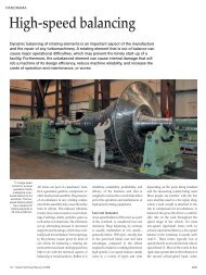
Continuous innovation requires state-of-the-art tools <strong>and</strong> equipment. Though numerical flow<br />
simulation (computational fluid dynamics, CFD) has evolved tremendously over recent years,<br />
it is the correct correlation of CFD prediction <strong>and</strong> real fluid testing that enables the develop -<br />
ment of pumps that fulfill the most stringent needs of clients <strong>and</strong> industry. Sulzer Pumps<br />
therefore operates test beds for both product development <strong>and</strong> final design validation.<br />
6<br />
1 Kotka (Finl<strong>and</strong>)<br />
research center.<br />
| Sulzer Technical Review 1/2011<br />
Sulzer Pumps delivers pumps<br />
for dem<strong>and</strong>ing applications <strong>and</strong>,<br />
at the same time, continuously<br />
improves the technology in order to<br />
be able to meet tomorrow’s customer<br />
challenges. According to the testing<br />
requirements of these two tasks, Sulzer<br />
runs test beds all over the world—each<br />
dedicated to the needs of specific<br />
products <strong>and</strong> markets. Among these<br />
are the world’s largest installations<br />
for full pump string testing at Leeds<br />
(UK)—with an installed drive power<br />
of 30 MW— <strong>and</strong> the recently opened<br />
largest Sulzer Pumps factory in<br />
Suzhou (China) with a test bed featuring<br />
eight stations <strong>and</strong> a total power<br />
supply of 15 MW. Key to the success of<br />
Sulzer is its capability to fully test every<br />
pump prior to shipping to ensure<br />
performance <strong>and</strong> problem-free commissioning.<br />
Adapted test installation<br />
In Sulzer’s competence center for process<br />
pumps in Kotka (Finl<strong>and</strong>), the test loop<br />
is set up to allow the rapid testing of<br />
end suction pumps of all sizes for the<br />
pulp <strong>and</strong> paper, food, metal, <strong>and</strong><br />
fertilizer industries, as well as desalination<br />
processes. The relatively high production<br />
volume of the process pump<br />
range requires adapted installations. In<br />
order to deliver thous<strong>and</strong>s of pumps per<br />
4328
year, the test setup needs to be st<strong>and</strong>ardized<br />
with a high turnover. The required<br />
rapid setup <strong>and</strong> breakdown is achieved<br />
with modular pump interface piping<br />
that can be quickly rotated into position<br />
using custom-built rotating assemblies<br />
holding the required range of suction<br />
<strong>and</strong> discharge pipe sizes.<br />
At the factories there are test beds for<br />
each pump type with multiple test beds<br />
for different sizes. Apart from a general<br />
test station for vertical pumps, process<br />
pumps, <strong>and</strong> multistage pumps with<br />
power up to 500 kW, the newest <strong>and</strong><br />
largest operation test bed of Sulzer<br />
Process Pumps is the test station for large<br />
process pumps. In this test bed, mea -<br />
surements can be carried out with high<br />
flow together with low pressure on the<br />
suction side. Such tests with pressures<br />
close to the vapor pressure in the suction<br />
pipe in combination with high flow rates<br />
are very important in the design phase<br />
of high specific speed pumps. One use<br />
of this low-pressure test rig is the simulation<br />
of pumping conditions in large<br />
evaporators.<br />
Energy efficiency<br />
Very similar test beds are available<br />
in the product development test bed<br />
in the Kotka research center 1. The<br />
medium-consistency pulp pump loop—<br />
with power up to 600 kW, flow rates up<br />
to 1200 l/s, <strong>and</strong> pressures up to 25 bar—<br />
conforms to the requirements of the pulp<br />
2 Energy recovery system.<br />
<strong>and</strong> paper industry. In this loop, the<br />
usual test materials are multiphase suspensions<br />
with gas, most commonly a<br />
mixture of water, pulp fibers, <strong>and</strong> air.<br />
To optimize the energy efficiency of<br />
the tests, equipment for energy recovery<br />
will be installed in the multistage pump<br />
loop in Finl<strong>and</strong> 2. A Pelton turbine connected<br />
to the same shaft train as motor<br />
<strong>and</strong> pump will recover the high pressure<br />
created by the pump. This setup will<br />
allow testing of multistage pumps at<br />
2.7 MW power while taking only 1.4 MW<br />
from the grid. At optimum conditions,<br />
only one quarter of the pump energy is<br />
taken from the grid. At the same time,<br />
the turbine reduces pressure with high<br />
efficiency <strong>and</strong> with much lower noise<br />
emission than when dissipating—<strong>and</strong><br />
thus losing—the energy in the valves.<br />
The hydraulics group in Finl<strong>and</strong> has<br />
optimized both the energy efficiency of<br />
the new multistage pump for reverse<br />
osmosis <strong>and</strong> of the associated test bed.<br />
This test bed will be used to validate the<br />
hydraulic <strong>and</strong> mechanical improvements<br />
to the existing multistage pump range<br />
<strong>and</strong> to develop new pump sizes. Needle<br />
valves with electric actuators control the<br />
turbine of the energy recovery system,<br />
which means the test loop operator<br />
using a Pelton turbine will see no difference<br />
in the loop operating philosophy.<br />
A test series for a pump with a drive<br />
power requirement of 1.4 MW will be<br />
carried out with just 400 kW of loss.<br />
Comparisons with a traditional test<br />
setup shows that the test rig will save<br />
8000 kWh of electric power in a single<br />
day. As a usual test series for one pump<br />
hydraulic takes about 20 days, with the<br />
new energy saving test rig, the environmental<br />
benefits <strong>and</strong> cost savings are<br />
significant.<br />
<strong>Testing</strong> before delivery<br />
In addition to aiding the development<br />
of new products, testing also ensures the<br />
<strong>quality</strong> of the output. All pumps leaving<br />
the production plant of Sulzer in Leeds<br />
are fully tested to both international st<strong>and</strong>ards<br />
<strong>and</strong> customer-specific requirements.<br />
On this test bed, highly engineered<br />
pumps <strong>and</strong> packages (including the<br />
contract driver) for the upstream oil <strong>and</strong><br />
gas industry are tested before delivery<br />
to site.<br />
This enormous facility is equipped<br />
with the required systems to test pumps<br />
driven by gas turbines of up to 30 MW,<br />
large diesel engines, <strong>and</strong> high-voltage<br />
electric motors. Recent modifications<br />
to the power grid gave Sulzer in the<br />
UK access to 45 MW of electrical power<br />
<strong>and</strong> two in-house variable-speed drives<br />
(VSD). The test bed provides sufficient<br />
space to install multiple skids, including<br />
pump <strong>and</strong> driver, <strong>and</strong>, if required, the<br />
contract VSD plus all of the support<br />
equipment, such as mechanical seal <strong>and</strong><br />
lubrication systems.<br />
TESTING AND QUALITY<br />
3 With seven singular test loops, the test bed in Oberwinterthur<br />
is highly flexible.<br />
Sulzer Technical Review 1/2011 |<br />
7
TESTING AND QUALITY<br />
4 Rapid prototyping<br />
using NC machining<br />
speeds up the<br />
manufacturing of the<br />
test components.<br />
This ability to rapidly test large<br />
amounts of equipment shows the<br />
facility’s testing flexibility <strong>and</strong> highlights<br />
the knowledge base available at Sulzer<br />
Pumps. These tests ensure that all<br />
systems are working in synergy before<br />
their arrival on site, thus removing<br />
potential delays to the site’s commissioning<br />
program.<br />
<strong>Testing</strong> validates CFD design<br />
In Oberwinterthur (Switzerl<strong>and</strong>), Sulzer<br />
Pumps operates a dedicated test bed,<br />
which supports product development,<br />
large contract-related development<br />
projects, <strong>and</strong> fundamental research 3.<br />
5 String test of a gas-turbine-driven pump at Sulzer facility in Leeds, UK.<br />
8 | Sulzer Technical Review 1/2011<br />
This development test bed is part of the<br />
development process for new products<br />
or pump ranges as well as of special<br />
large engineered pumps. The hydraulics<br />
group in Switzerl<strong>and</strong> has significantly<br />
contributed to the design of new pump<br />
ranges with a greenfield approach. For<br />
example, the model testing in Winterthur<br />
verified the CFD analysis <strong>and</strong> hydraulic<br />
design of pumps developed for a new<br />
pipeline in Eastern Asia.<br />
The main goal of the development test<br />
bed is the validation of all characteristics<br />
of a newly developed hydraulic before<br />
it is used in a new pump design. For<br />
this purpose, the validation tests are<br />
executed on scaled model pumps<br />
produced in aluminum using rapid prototyping<br />
(mainly NC machining) 4. The<br />
test bed features seven small-to-medium<br />
size loops that are designed to allow<br />
high flexibility in terms of the type of<br />
pumps that can be tested—with one<br />
loop devoted to two-phase testing for<br />
the development of the Sulzer multiphase<br />
pumps.<br />
During these development tests, all<br />
st<strong>and</strong>ard pump characteristics, such as<br />
flow, head, power, efficiency, <strong>and</strong> net<br />
positive suction head (NPSH) are<br />
recorded. NPSH is an important value<br />
relating to cavitation behavior of the<br />
pumps; it describes the difference<br />
between the actual pressure of a liquid<br />
<strong>and</strong> its vapor pressure at a given temperature.<br />
Additionally, all relevant information<br />
is measured that may be needed<br />
for the final design of a pump or in order<br />
to ensure its proper behavior under site<br />
conditions. These additional tests include:<br />
• internal pressure measurements in<br />
order to identify the losses in the different<br />
hydraulic components<br />
• radial- <strong>and</strong> axial-static <strong>and</strong> -dynamic<br />
load measurements<br />
• pressure pulsation measurement at<br />
suction <strong>and</strong> discharge<br />
• visualization of cavitation bubbles on<br />
the suction side <strong>and</strong> occasionally on<br />
the pressure side of the vanes<br />
• measurement of pressures, vibrations,<br />
or stresses in the rotating parts of the<br />
pump, i.e., within the impellers in<br />
very special cases<br />
Research on the impact of surface<br />
roughness<br />
For the development of high-performance<br />
pumps, both advanced CFD <strong>and</strong><br />
high-accuracy measurement are needed;<br />
these involve specialized tools <strong>and</strong><br />
highly trained personnel. Sulzer Pumps<br />
has invested heavily into both to ensure<br />
continuing success <strong>and</strong> has used the<br />
test results to validate CFD data for<br />
many years. Due to these efforts, the<br />
Sulzer experts know the application<br />
limits of CFD for the design of pump<br />
hydraulics. Within these limits, design<br />
correlations linking CFD results <strong>and</strong><br />
geometric design parameters give essential<br />
support during the design of new<br />
hydraulic contours.<br />
Modern research requires the interaction<br />
of measurements <strong>and</strong> CFD calculations<br />
in order to improve the accuracy<br />
of the design process. Currently, Sulzer<br />
specialists are particularly engaged in<br />
examining the use of CFD calculations<br />
in predicting the influence of surface<br />
roughness on pump performance. In<br />
order to calibrate the various models<br />
for surface roughness in the CFD codes,<br />
the developers need surface <strong>quality</strong><br />
measurements of the pump parts, mea -<br />
surements of their hydraulic per -<br />
formance, <strong>and</strong> CFD calculations, including<br />
manufacturing-<strong>quality</strong> models.<br />
In the Finnish R&D location, an extensive<br />
test program for new multistage<br />
pump hydraulics <strong>and</strong> mechanics will<br />
start in 2011. For this pump, every<br />
wetted surface has been calculated by<br />
CFD. Consequently, expected hydraulic<br />
performance, leakage losses, <strong>and</strong> force<br />
balancing are based on CFD calculations.<br />
During these tests, the Sulzer engineers<br />
expect to gain more in-depth knowledge<br />
about the validity of the applied CFD<br />
surface roughness model.<br />
Visualization of cavitation<br />
For projects with dem<strong>and</strong>ing suction<br />
performance or where high-suction<br />
energy leads to a high risk of erosion<br />
due to cavitation, Sulzer performs<br />
bubble tests on the test rig in Oberwinterthur.<br />
These bubble tests are used to<br />
assess the extent of cavitation develop-
ment as a function of suction pressure<br />
or NPSH. For this purpose, model<br />
pumps are equipped with large windows<br />
allowing visual access to the entire eye<br />
of the suction impeller over 360°. Sulzer<br />
Pumps uses the high competencies of<br />
Sulzer Innotec in complex NC machining<br />
for the production of these model<br />
pumps. These skills are needed to successfully<br />
machine the complex 3D<br />
contours of casings <strong>and</strong> impellers out<br />
of solid blocks of aluminum.<br />
The window at the suction side allows<br />
the experimental confirmation of the<br />
suction pressure at which the first<br />
bubbles are visible on the vane surface<br />
at all positions of the impeller within<br />
the pump inlet casing. It also allows the<br />
identification of the cavitation length for<br />
a given suction pressure <strong>and</strong>, consequently,<br />
the estimation of the according<br />
risk of erosion.<br />
Because the pressure side of the vane<br />
is not visible in the impeller eye if fully<br />
metallic vanes are used, in order to also<br />
confirm the cavitation development on<br />
the pressure side of the vanes, one or<br />
two vanes of the development impellers<br />
are machined from acrylic glass. The estimation<br />
of cavitation is especially important<br />
for large injection pumps for the<br />
petroleum industry or for large boiler<br />
feed pumps for thermal power plants<br />
for which the suction energy <strong>and</strong> the<br />
risk of cavitation erosion may be very<br />
high.<br />
6 Subsea test bed at Sulzer facility in Leeds, UK.<br />
Focus on prototype performance<br />
When a model pump is used in the development<br />
of new suction impellers for<br />
these applications, it is designed at prototype<br />
scale. This procedure allows the<br />
job impellers to be tested in order to<br />
confirm cavitation-free operation on site.<br />
Because of the presence of a window<br />
that limits the suction pressure, as a compromise,<br />
tests are performed at a<br />
reduced speed compared with site conditions,<br />
<strong>and</strong> the full-speed performance<br />
is calculated using st<strong>and</strong>ard affinity<br />
laws.<br />
The development test bed is also used<br />
to check the mechanical performance of<br />
key elements of pumps, such as bearings<br />
or seals. For example, dedicated testing<br />
equipment has been developed in order<br />
to test different material combinations<br />
for the product-lubricated line shaft<br />
bearings under real site conditions using<br />
water charged with s<strong>and</strong>.<br />
Prepared for future dem<strong>and</strong>s<br />
Sulzer Pumps continuously develops<br />
<strong>and</strong> improves the testing methods for<br />
new products <strong>and</strong> for machines. For<br />
example, the dem<strong>and</strong> for subsea<br />
pumping is growing, along with the<br />
requirements that pumps operating<br />
under water have to fulfill. To be able<br />
to test subsea processing equipment<br />
under realistic conditions, Sulzer is<br />
investing in a dedicated multiphase<br />
subsea test bed in the UK. This state-ofthe-art<br />
addition to the already impressive<br />
string testing facilities in Leeds 5 will<br />
position Sulzer as the market leader with<br />
respect to pump-testing facilities. In this<br />
installation, it will be possible to<br />
examine subsea pump/motor packages<br />
with weights approaching 100 tons in<br />
water depths of up to 10 m 6.<br />
When deployed in the open ocean,<br />
these pumps will operate in many kilometers<br />
of water depth <strong>and</strong> are designed<br />
to take high external <strong>and</strong> internal pressures<br />
whilst delivering the high pressure<br />
rises that customers require. The first<br />
pump that will be tested once the test<br />
bed is commissioned will be a 3 MW,<br />
6000 rpm multiphase pump able to<br />
deliver over 100 bar pressure rise—well<br />
suited for many of the current subsea<br />
applications.<br />
Current specifications <strong>and</strong> market<br />
ideas set the st<strong>and</strong>ards for capabilities<br />
<strong>and</strong> capacity of any new test bed. Sulzer,<br />
however, follows the motto “designing<br />
for the future” <strong>and</strong> requires that new<br />
test installations must consider future<br />
possibilities for expansion. Sulzer thereby<br />
plans to keep these investments operational<br />
<strong>and</strong> useful for many years, as both<br />
products <strong>and</strong> markets mature <strong>and</strong> adapt.<br />
This philosophy makes it possible for<br />
Sulzer Pumps to deliver pumps adapted<br />
to market <strong>and</strong> client requirements now<br />
<strong>and</strong> in future years.<br />
TESTING AND QUALITY<br />
Matt Bourne<br />
Sulzer Pumps (UK) Ltd.<br />
Manor Mill Lane<br />
Leeds, LS11 8BR<br />
UK<br />
Phone +44 113 272 5704<br />
matt.bourne@sulzer.com<br />
Matti Koivikko<br />
Sulzer Pumps Finl<strong>and</strong> Oy<br />
P.O.Box 66<br />
48601 Kotka<br />
Finl<strong>and</strong><br />
Phone +358 50 555 0268<br />
matti.koivikko@sulzer.com<br />
Philippe Dupont<br />
Sulzer Pumps Ltd.<br />
Zürcherstrasse 12<br />
8401 Winterthur<br />
Switzerl<strong>and</strong><br />
Phone +41 52 262 40 30<br />
philippe.dupont@sulzer.com<br />
Sulzer Technical Review 1/2011 |<br />
9
TESTING AND QUALITY<br />
Driving development through an exp<strong>and</strong>ed “global-local” organization<br />
The key to application-tailored<br />
coating materials<br />
Sulzer Metco produces coating materials with clear customer benefits thanks to stateof-the-art<br />
facilities, globally coordinated teams, <strong>and</strong> superior manufacturing capabilities.<br />
Customers profit from many application-tailored new materials <strong>and</strong> solutions.<br />
10<br />
| Sulzer Technical Review 1/2011<br />
New <strong>and</strong> emerging markets are<br />
increasing the need for cuttingedge,<br />
engineered coating solutions.<br />
At the same time, the challenge in<br />
existing markets is to lower coating<br />
application costs, innovatively reuse <strong>and</strong><br />
recycle materials, address <strong>and</strong> find<br />
suitable alternatives for critical raw<br />
materials, <strong>and</strong>, in particular, to have<br />
more predictable <strong>and</strong> robust coatings.<br />
“Designed to cost <strong>and</strong> purpose” (application<br />
<strong>and</strong> service conditions) coating<br />
solutions should start with the choice of<br />
the most suitable coating material. This<br />
The pilot atomizer allows Sulzer to efficiently provide experimental powders in quantities of 5 to 100kg.<br />
method requires an in-depth approach<br />
that examines: how material characteristics<br />
<strong>and</strong> coating properties are influenced<br />
by the choice of materials manufacturing<br />
processes <strong>and</strong> parameters; the<br />
subtleties of choosing one raw material<br />
instead of another; <strong>and</strong> material charac-<br />
4329
teristics such as apparent density, surface<br />
area, particle morphology <strong>and</strong> structure,<br />
<strong>and</strong> other key physical properties. Such<br />
factors must be considered to a far<br />
greater degree than in the past, where<br />
coating engineers would traditionally<br />
just focus on selecting a material<br />
based on chemistry <strong>and</strong> particle size<br />
distribution <strong>and</strong> modify coating characteristics<br />
by varying the spray equipment<br />
<strong>and</strong> parameters 1.<br />
Exp<strong>and</strong>ed material research <strong>and</strong><br />
development capabilities<br />
Sulzer Metco’s Materials Business Unit<br />
provides powder, wire, <strong>and</strong> specialty rod<br />
materials for coating applications such<br />
as thermal spray, laser cladding, <strong>and</strong><br />
plasma-transferred arc (PTA), as well as<br />
for processes such as high-temperature<br />
brazing, pack diffusion, specialty welding,<br />
<strong>and</strong> electronic filler applications. The<br />
products offered range from many types<br />
of oxide ceramics, carbides, cermets,<br />
metals, <strong>and</strong> metal alloys—including<br />
superalloys, MCrAlYs, self-fluxing<br />
materials, <strong>and</strong> various blends or clad<br />
combinations of these materials.<br />
Sulzer Metco’s mission is not only to<br />
continue to lead this particular market<br />
1 Influence of manufacturing process for<br />
alumina-13 titania powders on deposition<br />
efficiency sprayed with a Sulzer Metco<br />
TriplexPro-200™ gun (similar microstructures).<br />
Deposition efficiency (%)<br />
100<br />
80<br />
60<br />
40<br />
20<br />
0<br />
100 µm<br />
Metco 6221<br />
A&S<br />
Metco 130<br />
Mechanical Clad<br />
Amdry 6228<br />
F&C/Blend<br />
with lean, high-volume material manufacturing<br />
using in-place, state-of-the-art<br />
<strong>quality</strong> systems, but also to address the<br />
need for faster, more efficient, <strong>and</strong><br />
higher-impact innovation based on<br />
cutting-edge product development. This<br />
includes fast availability of test powders<br />
for sampling purposes, assurance of efficient<br />
prototype-to-production transfer<br />
<strong>and</strong> scale-up capability, <strong>and</strong> responsiveness<br />
to the customers’ needs based on<br />
expert knowledge of how to tailor<br />
coating materials to achieve specific<br />
coating performance <strong>and</strong> application<br />
dem<strong>and</strong>s.<br />
A specialized infrastructure is needed<br />
that allows the rapid manufacture of<br />
small batches of materials with full flexibility<br />
to widely vary material processing<br />
parameters, manufacturing technologies,<br />
<strong>and</strong> chosen raw materials. It also<br />
requires the ability to test the resulting<br />
material <strong>and</strong> coating characteristics,<br />
properties, <strong>and</strong> performance quickly.<br />
Consequently, Sulzer Metco has<br />
strengthened <strong>and</strong> exp<strong>and</strong>ed its materials<br />
research <strong>and</strong> development (R&D) capabilities<br />
over the last several years.<br />
Powder development <strong>and</strong> pilot labs<br />
R&D powder development laboratories<br />
were established at each of the four<br />
material manufacturing sites, <strong>and</strong> they<br />
were equipped with the latest processing<br />
equipment <strong>and</strong> cutting-edge characterization<br />
technologies 2. Each powder<br />
development laboratory has specialized<br />
core competencies that, at minimum,<br />
mirror the manufacturing methods available<br />
at that particular plant.<br />
• Westbury, NY, USA: The powder<br />
development laboratory at Westbury,<br />
the largest of the powder labs, has<br />
undergone a major expansion <strong>and</strong><br />
refurbishment over the last 2.5 years.<br />
Pilot equipment for high-energy ball<br />
milling, attrition milling, jet milling,<br />
sintering, mechanical cladding, screen-<br />
ing, <strong>and</strong> air classification were added.<br />
This laboratory is now able to deliver<br />
HOSP™ ceramics, agglomerated <strong>and</strong><br />
sintered ceramics, mechanically clad<br />
metal <strong>and</strong> ceramic test powders, <strong>and</strong><br />
blends of various material families. It<br />
can produce these test lots in quantities<br />
up to several hundred kilograms—<br />
completely independently of the production<br />
facilities 3.<br />
• Troy, MI, USA: The powder laboratory<br />
at the Troy plant specializes in<br />
gas atomization, including a newly<br />
installed pilot atomizer. Screening, air<br />
classification, <strong>and</strong> blending capabilities<br />
are currently in the works. Based on<br />
these, the lab will be able to efficiently<br />
provide experimental powders in<br />
quantities of 5 to 100 kilograms. The<br />
Troy lab is focused on evaluating the<br />
influence of atomization parameters<br />
on powder characteristics <strong>and</strong> yields,<br />
testing various atomization devices,<br />
<strong>and</strong> developing new chemistries 4.<br />
• Barchfeld, Germany (WOKA): The<br />
WOKA powder laboratory, which<br />
started up in 2009, has a small spray<br />
dryer, a tablet press, several furnaces,<br />
crushing equipment with hard metal<br />
tools, <strong>and</strong> an air classifier combined<br />
with a jet mill. The lab can produce<br />
agglomerated <strong>and</strong> sintered ceramics<br />
<strong>and</strong> carbides as well as sintered <strong>and</strong><br />
crushed carbides as test powders.<br />
• Fort Saskatchewan AB, Canada<br />
(SMCA): At the SMCA development<br />
TESTING AND QUALITY<br />
2 Cutting-edge characterization technologies:<br />
New scanning electron microscope with energy-dispersive X-ray<br />
spectroscopy (Materials R&D in Westbury, NY, USA).<br />
Sulzer Technical Review 1/2011 |<br />
11
TESTING AND QUALITY<br />
3 High-energy ball mill (R&D lab in Westbury, NY, USA).<br />
12 | Sulzer Technical Review 1/2011<br />
laboratory, a large variety of powders<br />
are chemically clad using hydrometallurgy<br />
technology. The volumes<br />
produced are suitable for thermalspray<br />
testing <strong>and</strong> developmental lots<br />
using a laboratory-sized pilot autoclave<br />
5. This facility also has the capability<br />
to resize, dry, <strong>and</strong> furnace-heat-treat<br />
powders in different atmospheres,<br />
thereby fully reproducing the capabilities<br />
of the actual production facilities.<br />
In this manner, new materials can be<br />
developed in fully scalable conditions.<br />
The materials R&D lab also features<br />
scale-up development <strong>and</strong> commercial<br />
production of high-<strong>quality</strong>, goldcoated<br />
nickel-based composite<br />
powders using a proprietary process.<br />
These materials are primarily used for<br />
electronic <strong>and</strong> military applications.<br />
Coating research labs<br />
Beside the powder development labs,<br />
the coating research laboratories are an<br />
important part of Sulzer Metco’s materials<br />
R&D capabilities. The focus of these<br />
labs is to enable initial, fast, in-house<br />
testing of coatings produced using<br />
the experimental powders—an essential<br />
step in screening promising material c<strong>and</strong>idates.<br />
In this way, correlations can be<br />
drawn quickly between material characteristics<br />
<strong>and</strong> coating properties.<br />
The engineers can then optimize the<br />
materials manufacturing processes <strong>and</strong><br />
the manufacturing parameters to tailor<br />
materials to specific application <strong>and</strong><br />
service conditions. The available equipment<br />
includes salt spray, climate<br />
chambers, <strong>and</strong> electrochemical equipment<br />
for corrosion testing, various wear<br />
testers, <strong>and</strong> thermal-cycle furnaces. A<br />
burner rig <strong>and</strong> a cavitation wear tester<br />
were recently added 6.<br />
4 “A new MCrAlY in the making”: pilot atomizer (Materials R&D in Troy, MI, USA).<br />
For final validation <strong>and</strong> testing of<br />
coating properties beyond the in-house<br />
capabilities, Sulzer Metco calls on an<br />
extensive partner network of respected<br />
research <strong>and</strong> testing facilities that extend<br />
its coating testing capabilities even<br />
further. As an example, Sulzer Metco<br />
Materials, through its cooperation with<br />
Sulzer Innotec in Winterthur, Switzerl<strong>and</strong>,<br />
has a cutting-edge abradable test rig at<br />
its disposal. The rig is a vital tool for<br />
Sulzer Metco <strong>and</strong> its OEM aerospace <strong>and</strong><br />
industrial gas turbine partners for joint<br />
abradable development programs.<br />
The facility is the largest <strong>and</strong> most<br />
sophisticated of its kind—with the<br />
ability to test shroud temperatures<br />
up to 1200 °C using a variety of blade,<br />
knife-edge seal, or labyrinth seal strip<br />
configurations at a wide range of tip<br />
speeds <strong>and</strong> incursion rates. A recently<br />
installed high-speed infrared pyrometer<br />
provides additional vital risk-mitigation<br />
information on friction heating arising<br />
at shroud-blade interfaces during incursion.<br />
The advantages of a “global-local”<br />
approach<br />
Since each powder development laboratory<br />
is located at its relevant manufacturing<br />
site, R&D, production, <strong>and</strong><br />
<strong>quality</strong> control can exchange know-how<br />
efficiently; they can optimize the use of<br />
the analytical instrumentation; <strong>and</strong> they<br />
can piggyback on the logistics infrastructure<br />
of the plant. Time to market is minimized<br />
through the effective <strong>and</strong> timely<br />
introduction of successfully validated<br />
development products into large-scale<br />
manufacturing.<br />
For example, the installation <strong>and</strong><br />
operation at Sulzer Metco WOKA of a<br />
new sintered- <strong>and</strong> crushed-carbide production<br />
line, based on process development<br />
by the local R&D group has<br />
resulted in a wide range of new <strong>and</strong><br />
more economical products within a very<br />
short time—demonstrating the success<br />
of this concept.
Nevertheless, a global approach is<br />
needed, as well. Good examples are<br />
agglomerated <strong>and</strong> sintered lanthanum<br />
strontium manganite (LSM) <strong>and</strong> spherical<br />
titanium oxide (TiOx) ceramic products,<br />
which took advantage of the development<br />
expertise of the Westbury materials<br />
R&D team, but are manufactured at<br />
Sulzer Metco WOKA in a newly established<br />
facility.<br />
A global approach not only allows<br />
optimal resource usage, knowledge<br />
exchange, <strong>and</strong> utilization of expertise, it<br />
also guarantees that the best coating—<br />
<strong>and</strong>, therefore, the best product solution—<br />
is offered to the customer. This is particularly<br />
important as powders with the<br />
same chemistry can be manufactured at<br />
the various sites using different manufacturing<br />
processes resulting in quite different<br />
coating properties. It is therefore<br />
important to select the manufacturing<br />
process independently of the plant or<br />
the location of the R&D lab <strong>and</strong> instead<br />
base it solely on the application <strong>and</strong><br />
service requirements.<br />
Globally operating materials R&D<br />
project managers <strong>and</strong> competence leaders<br />
who drive <strong>and</strong> coordinate all research<br />
6 Furnace testing (thermal cycle).<br />
activities <strong>and</strong> who use the various local<br />
powder <strong>and</strong> coating research labs for<br />
their experimental work maintain the<br />
balance between the local <strong>and</strong> global<br />
approaches. The projects are managed<br />
based on Sulzer’s systematic multistage<br />
innovation process <strong>and</strong> are carried out<br />
with the support of cross-functional <strong>and</strong><br />
multiregional project teams.<br />
Customer benefits<br />
A globally coordinated team that has<br />
state-of-the-art facilities at its disposal,<br />
combined with local mirroring of manufacturing<br />
capabilities, <strong>and</strong> internal <strong>and</strong><br />
external networking allows Sulzer Metco<br />
to produce coating materials with clear<br />
5 An experimental autoclave enables quick changes in process parameters<br />
<strong>and</strong> efficient material development.<br />
Temperature (°C)<br />
1250<br />
1000<br />
750<br />
500<br />
250<br />
customer benefits. In the past year alone,<br />
a record number of test powders were<br />
produced for customers, <strong>and</strong> many<br />
application-tailored new materials were<br />
developed <strong>and</strong> released to the market.<br />
Notably, several of these developments<br />
did not involve the need for new coating<br />
chemistries. Some of those examples<br />
include:<br />
• New spherical titania powders (TiOx)<br />
with various x-factors that permit the<br />
customer to produce coatings with<br />
higher-than-usual deposition efficiencies<br />
at very high feed rates, which are<br />
essential criteria for sputter target<br />
applications<br />
• Spherical ceramics such as alumina<br />
<strong>and</strong> alumina-titania designed to<br />
produce coatings faster <strong>and</strong> with less<br />
material waste while fulfilling specific<br />
porosity requirements<br />
• Cost-effective carbide materials for<br />
aerospace applications with excellent<br />
coating deposit efficiencies that do not<br />
sacrifice wear resistance.<br />
Sulzer Metco is committed to leading<br />
the market with application-tailored <strong>and</strong><br />
economical coating solutions that meet<br />
the needs of our customers.<br />
Montia C. Nestler<br />
Sulzer Metco (US) Inc.<br />
1101 Prospect Ave.<br />
Westbury, NY 11590-0201<br />
USA<br />
Phone +1 516 338 2305<br />
montia.nestler@sulzer.com<br />
TESTING AND QUALITY<br />
0<br />
500 1000 1500<br />
Time (min)<br />
Sulzer Technical Review 1/2011 |<br />
13
TESTING AND QUALITY<br />
Revealing <strong>and</strong> interpreting hidden features using dedicated signal analysis<br />
Filter <strong>and</strong> fit<br />
Based on the signals of only a few sensors, Sulzer Innotec was successful in identifying<br />
the most important natural frequencies <strong>and</strong> vibration mode shapes of a pump impeller.<br />
The results are, essentially, in good agreement with the FEM calculations performed by<br />
Sulzer Pumps. The measurement results indicate that the mechanical resonances are quite<br />
well damped, so that they will not jeopardize the integrity of the impeller in any way.<br />
1 Positions of strain<br />
gauges <strong>and</strong><br />
accelerometers on the<br />
impeller (axial view)<br />
(Source: PhD. thesis<br />
by Stefan Berten)<br />
14<br />
| Sulzer Technical Review 1/2011<br />
In 2009, Sulzer Innotec received an<br />
order from the Sulzer Pumps division<br />
to analyze <strong>and</strong> assess vibration<br />
signals measured in a pump test st<strong>and</strong>.<br />
The test pump that was examined is the<br />
reproduction of the last stage of a highpressure<br />
centrifugal pump operated by<br />
a variable-speed drive. This impeller<br />
stage has a rated power of 1.4MW.<br />
The impeller has seven blades <strong>and</strong> a<br />
diameter of 0.35m. In centrifugal pumps,<br />
rotor-stator interactions <strong>and</strong> flow separation<br />
phenomena are known to excite<br />
vibrations of stationary or rotating components,<br />
which might result in fatigue<br />
failure. Based on performance monitoring<br />
of a particular pump stage in part-load<br />
SG6<br />
SG7<br />
SG5<br />
SG4<br />
SG8<br />
Acc3<br />
Acc = Accelerometer<br />
SG = Strain gauge<br />
SG1<br />
SG3<br />
Acc1<br />
Acc2<br />
SG2<br />
conditions, Sulzer Pumps assigned an<br />
extensive experimental investigation of<br />
the mechanical <strong>and</strong> hydraulic oscillations<br />
to the EPFL (École Polytechnique Fédérale<br />
de Lausanne).<br />
Many sensors for pressure, strain,<br />
acceleration, <strong>and</strong> displacement were<br />
installed in order to record the corresponding<br />
oscillations. All measurements<br />
were performed by the Laboratoire de<br />
Machines Hydrauliques (LMH) of the<br />
EPFL <strong>and</strong> analyzed, for the most part,<br />
in the context of a PhD. thesis.<br />
Customized analysis of the impeller<br />
mode shapes<br />
The task of Sulzer Innotec consisted of<br />
identifying the operational vibration<br />
mode shapes of the rotating impeller<br />
based on the measurement signals of the<br />
strain gauges <strong>and</strong> accelerometers<br />
installed on the impeller <strong>and</strong> assessing<br />
the results <strong>and</strong> comparing them with the<br />
results from FEM calculations.<br />
For certain operating conditions, a frequency<br />
excited by the stationary components<br />
might coincide with a weakly<br />
damped natural frequency of the impeller<br />
<strong>and</strong> might result in substantial resonance<br />
amplitudes. Conversely, a lack of strong<br />
resonant vibrations despite excitation at<br />
the resonance frequency indicates that<br />
the corresponding resonance is highly<br />
damped.<br />
The task of Sulzer Innotec was to<br />
analyze the vibration signals of two<br />
speed ramps—one run-up <strong>and</strong> one coastdown.<br />
Figure 1 indicates the positions<br />
of the eight strain gauges <strong>and</strong> three<br />
accelerometers installed on the impeller.<br />
Conditioning of strain gauge signals<br />
The recorded strain gauge signals were<br />
considerably affected by noise; substantial<br />
noise sources were sensor noise, bit noise<br />
of the analog digital converter ADC, <strong>and</strong><br />
cross talk of external signals. The comparison<br />
of all strain gauge signals showed<br />
that these signals are mostly in phase <strong>and</strong><br />
have similar amplitudes. The conclusion<br />
was that the signals were seriously<br />
affected by strong cross talk of an external<br />
signal. Therefore, as a first step of signal<br />
conditioning, the average value of all<br />
strain gauge signals was subtracted from<br />
each individual signal; thereby, the noise<br />
level could be substantially reduced. The<br />
resulting spectrograms now revealed the<br />
typical series of order lines, which result<br />
from the excitation at integer multiples<br />
of the pump rotation frequency. In particular,<br />
the orders 12, 24, <strong>and</strong> 36 are clearly<br />
prominent, as expected for a pump<br />
equipped with 12 diffuser guide vanes.<br />
4330
Acceleration (g)<br />
40<br />
30<br />
20<br />
10<br />
0<br />
–10<br />
–20<br />
–30<br />
–40<br />
–50<br />
–60<br />
0 10 20 30 40<br />
Time (s)<br />
50 60 70<br />
2 Time traces of accelerometers showing implausible excursions in negative direction<br />
<strong>and</strong> clipping at –50 g.<br />
Signals of the accelerometer<br />
The accelerometer signals were not<br />
optimal either (see 2); they showed<br />
numerous implausible excursions in the<br />
negative direction <strong>and</strong> substantial<br />
clipping at approximately –50g. Nevertheless,<br />
in the frequency domain, the<br />
results obtained with the accelerometers<br />
were quite well defined compared with<br />
the results from strain gauges <strong>and</strong> were<br />
therefore used for further investigations.<br />
Resonance detection using<br />
spectrograms<br />
Spectrograms are a common method for<br />
displaying characteristics of transient<br />
vibration signals. Figure 3 shows an<br />
2500<br />
2000<br />
1500<br />
Frequency (Hz) 3000<br />
1000<br />
500<br />
Example 1: f = 1150 Hz<br />
(2-diameter mode,<br />
excitation by 23rd order)<br />
Example 2: f = 900 Hz<br />
(0-diameter mode,<br />
excitation by 21st order)<br />
example. The vibration levels are color<br />
coded <strong>and</strong> displayed as a function of<br />
time (= x-axis) <strong>and</strong> frequency (= y-axis).<br />
In the spectrogram of an accelerometer<br />
signal depicted in 3, the impeller natural<br />
frequencies are evident as horizontal,<br />
slightly fanned-out yellow-red shades<br />
(marked with red arrows in 3). The frequency<br />
b<strong>and</strong>width of the yellow-red<br />
shades is more than 100 Hz wide, indicating<br />
that the corresponding resonances<br />
feature considerable damping. A resonance<br />
with low damping would be<br />
evident by a rather narrow resonance<br />
b<strong>and</strong>width; no such feature crops up in<br />
the spectrogram of 3. Wherever the fanlike<br />
excitation frequencies of the rotor-<br />
0 10 20 30 40<br />
Time (s)<br />
50 60 70<br />
5-D<br />
3 Spectrogram of the accelerometer signal Acc1 (Ramp with decreasing speed; frequency<br />
b<strong>and</strong>s indicating resonances (yellow-red shades) marked by red arrows, resonances coinciding<br />
with a speed order line (circled in blue).<br />
4-D<br />
3-D<br />
2-D<br />
0-D<br />
1-D<br />
Deflection (–)<br />
1.0<br />
0.8<br />
0.6<br />
0.4<br />
0.2<br />
0<br />
–0.2<br />
–0.4<br />
–0.6<br />
–0.8<br />
–1.0<br />
stator interaction coincide with a natural<br />
frequency of the impeller (see bluecircled<br />
lines), the corresponding resonance<br />
is excited. However, thanks to substantial<br />
damping, the amplification of<br />
the amplitude is not significant, <strong>and</strong> no<br />
fatigue damage is expected due to these<br />
resonances.<br />
Deflection shape identification<br />
It is well known that any given excitation<br />
order of the stationary components can<br />
excite only certain mode shapes of the<br />
impeller (Tanaka, 1990). Once the resonance<br />
frequencies of the impeller have<br />
been identified from the spectrogram,<br />
measured data <strong>and</strong> theoretically<br />
computed rotor vibrations can be<br />
matched in order to determine the corresponding<br />
mode shapes of the impeller.<br />
Following are two examples:<br />
• Example 1: Two-diameter mode at<br />
f=1150 Hz excited by the 23rd order:<br />
The frequency response function<br />
between two accelerometer signals is<br />
computed <strong>and</strong> averaged for the time<br />
segment in which a certain resonance<br />
mode is excited by the suitable excitation<br />
order. Then, the ratio of<br />
vibration amplitudes <strong>and</strong> the phase<br />
difference can be determined at the<br />
resonance frequency (f = 1150 Hz); at<br />
this frequency, the coherence should<br />
be reasonably good. The amplitude<br />
ratios <strong>and</strong> the relative phase at the<br />
measurement points are then animated<br />
synchronously with the theoretical<br />
vibration mode shape, the amplitude<br />
<strong>and</strong> phase of which are manually<br />
adapted to match the measured data.<br />
Using this methodology, it was<br />
TESTING AND QUALITY<br />
0 50 100 150 200 250 300 350<br />
Wheel circumference (º)<br />
4 Instantaneous deflection of mode shape with two nodal diameters.<br />
Red: measured vibration signals; blue: theoretical mode shape.<br />
Sulzer Technical Review 1/2011 |<br />
15
TESTING AND QUALITY<br />
0.00 100.00 (mm)<br />
50.00<br />
5 Results of the FEM calculation for the two-diameter <strong>and</strong> three-diameter natural modes.<br />
verified that the mode shape with two<br />
nodal diameters is actually excited<br />
during operation. Figure 4 depicts an<br />
instantaneous deflection state of the<br />
particular vibration mode.<br />
• Example 2 : Zero-diameter mode at<br />
f=900 Hz excited by the 21st order:<br />
From the frequency response function<br />
for the resonant vibration at f = 900 Hz,<br />
it is evident that all three acceleration<br />
signals are in phase <strong>and</strong> have the<br />
same amplitude. This is clearly an axisymmetric<br />
mode with zero nodal<br />
diameters; in this case, verification<br />
by a synchronous animation of the<br />
measured signals <strong>and</strong> the computed<br />
mode shape is unnecessary.<br />
Comparison with results of the FEM<br />
calculation<br />
Finally, the measurement results were<br />
compared with the FEM calculations<br />
carried out by Sulzer Pumps 5. A rotor<br />
surrounded by water was used as<br />
boundary condition. The impeller was<br />
modeled as non-rotating, since stiffening<br />
due to centrifugal forces has only a negligible<br />
influence on the natural frequencies.<br />
Figure 6 shows a comparison of<br />
the measured <strong>and</strong> the computed natural<br />
frequencies.<br />
6 Comparison of the measured <strong>and</strong> computed natural frequencies.<br />
16 | Sulzer Technical Review 1/2011<br />
The frequencies are in good agreement,<br />
except for the «umbrella»-mode with a<br />
measured natural frequency of approx.<br />
900 Hz, vs. the FEM calculation resulting<br />
in a frequency of 701 Hz. This deviation<br />
could be due to a truncated shaft stub,<br />
which is included in the finite element<br />
model.<br />
Note that the forces induced by the<br />
12 diffuser guide vanes <strong>and</strong> acting on<br />
the impeller have lowest relevant excitation<br />
orders of 12 <strong>and</strong> 24; the corresponding<br />
excitation frequencies lie just below<br />
the matching natural modes of the<br />
impeller:<br />
• 12th order of the maximum pump<br />
speed: 1135 Hz ↔ natural frequency<br />
of two-diameter mode: 1150Hz<br />
• 24th order of the maximum pump<br />
speed: 2250 Hz ↔ nat. frequency of<br />
four-diameter mode: 2500Hz.<br />
Spatial aliasing<br />
With seven sensors that are equally<br />
spaced around the circumference, theoretically,<br />
only the vibration modes with<br />
zero to three nodal diameters can be<br />
detected positively. For vibration modes<br />
with four or more nodal diameters,<br />
spatial undersampling occurs due to the<br />
sensor arrangement, which has an insuf-<br />
Number of f [Hz] f [Hz] Remarks Excitation order<br />
nodal diameters<br />
approx. reading computed by FEM from spectrogram<br />
0 900 701 «umbrella»-mode 21<br />
1 750 757 «rocker»-mode 22<br />
2 1150 1199 23<br />
3 1900 1846 24<br />
4 2500 not computed by FEM 38<br />
Max.<br />
5 2800 not computed by FEM<br />
Min.<br />
50.00<br />
0.00 100.00 (mm)<br />
25.00 75.00<br />
ficient sensor density. For instance, mode<br />
shapes with 1 or 6 nodal diameters<br />
cannot be differentiated, since both<br />
modes would result in identical vibrations<br />
at the sensor positions.<br />
With the additional knowledge of the<br />
FEM results, the vibration mode shapes<br />
can usually be unambiguously identified,<br />
even with only three sensors. Without<br />
the combination with FEM results, a considerably<br />
denser sensor arrangement<br />
would be necessary in order to avoid<br />
spatial aliasing.<br />
Interpretation<br />
The vibrations measured during operation<br />
indicate that the natural frequencies<br />
of the impeller are near the predictions<br />
by the FEM. However, the resonances<br />
have sufficient damping so that the corresponding<br />
vibration levels remain well<br />
within acceptable limits <strong>and</strong> the integrity<br />
of the impeller is not at risk.<br />
Literature<br />
• Berten, S., Thesis EPFL No. 4642,<br />
http://library.epfl.ch/en/theses/?nr=4642<br />
• Tanaka, H., “Vibration behaviour <strong>and</strong> dynamic stress<br />
of runners of very high head reversible pump-turbines,”<br />
IAHR Symposium 1990, special session, Belgrade<br />
Ulrich Moser<br />
Sulzer Markets <strong>and</strong> Technology AG<br />
Sulzer Innotec<br />
Sulzer-Allee 25<br />
8404 Winterthur<br />
Switzerl<strong>and</strong><br />
Phone +41 52 262 82 61<br />
ulrich.moser@sulzer.com<br />
Hans Rudolf Graf<br />
Sulzer Markets <strong>and</strong> Technology AG<br />
Sulzer Innotec<br />
Sulzer-Allee 25<br />
8404 Winterthur<br />
Switzerl<strong>and</strong><br />
Phone +41 52 262 82 40<br />
hansrudolf.graf@sulzer.com
SULZER ANALOGY<br />
<strong>Testing</strong> poisons<br />
In the plant world, there are numerous poisons, which,<br />
when consumed, can lead to serious problems or even<br />
death for human beings. People always have to try<br />
something out first in order to determine whether it is<br />
poisonous or not. So how do animals know which plants<br />
to beware of <strong>and</strong> which are beneficial?<br />
Structural formula of<br />
the alkaloid morphine,<br />
which Friedrich Wilhelm<br />
Sertürner extracted<br />
from the opium poppy<br />
in pure form in 1806.<br />
The struggle for survival in the natural<br />
world takes place not only between<br />
hunting lions <strong>and</strong> fleeing gazelles. Even<br />
the apparently peaceful coexistence<br />
between plants <strong>and</strong> animals is an incessant<br />
battle with the aim of surviving<br />
long enough to pass on one’s own genes<br />
to the next generation. As plants are<br />
unable to flee their predators, they have<br />
to defend themselves from the hungry<br />
mouths of animals in other ways. Spines,<br />
thorns, <strong>and</strong> bristly hairs offer mechanical<br />
protection. Unpleasant odors may also<br />
discourage consumption. The most effective<br />
defenses, however, are plant toxins<br />
that punish the “attacker” with physical<br />
problems or even death.<br />
It’s purely the dosage that makes<br />
the poison<br />
The plant world has developed an<br />
incredible wealth of chemical defenses.<br />
Tannins are very astringent. They cause<br />
the tongue to contract, dry out the<br />
mouth <strong>and</strong> throat, <strong>and</strong> disturb digestion.<br />
The greatest poison arsenal, however,<br />
are the alkaloids, which can be found<br />
© Smellme | Dreamstime.com<br />
in 20 percent of all flowering plants.<br />
Anyone who does not regard the<br />
bitter taste as a warning will have to<br />
experience on this own body how these<br />
nerve agents work.<br />
Humans also know about these<br />
poisons—from the atropine in the<br />
deadly nightshade <strong>and</strong> the quinine in<br />
cinchona bark to the nicotine in tobacco<br />
<strong>and</strong> the caffeine in coffee. Like almost<br />
any poison, alkaloids are digestible in<br />
small dosages, <strong>and</strong> they can have a<br />
stimulating or intoxicating effect. Both<br />
humans <strong>and</strong> animals have learned that<br />
low quantities of alkaloids only damage<br />
microbes <strong>and</strong> insects, <strong>and</strong> thereby<br />
provide the body with some protection<br />
against certain infections <strong>and</strong> pests.<br />
How do animals know what is poisonous?<br />
In order to avoid risks, the<br />
p<strong>and</strong>a bear restricts itself to harmless<br />
bamboo plants—with the disadvantage<br />
that it has to consume enormous quantities<br />
of this plant, which is low in nutrition.<br />
The rat has a very different strategy.<br />
It is an omnivore <strong>and</strong> has conquered the<br />
entire world thanks to its flexibility. As<br />
poisons lurk everywhere, the rat is very<br />
mistrustful of new things. If it finds an<br />
unfamiliar food source, it only eats a<br />
mini-portion at first. Only if it does<br />
not suffer any adverse reaction does it<br />
consume the new discovery in larger<br />
quantities. Moreover, if it sees that other<br />
rats are eating a new food without any<br />
Black howler monkey: Consumes unknown plant material only in small<br />
quantities in order to avoid a possible poisoning.<br />
problem, the rat knows that it can also<br />
eat the new food.<br />
Poison training course for rat<br />
embryos<br />
The poison training course for rats starts<br />
in the womb, where the embryo<br />
develops aversions to noxious smells<br />
<strong>and</strong> a preference for safe tastes. In<br />
mammals, young animals learn with<br />
their mother’s milk how good food<br />
smells <strong>and</strong> tastes. Moreover, when the<br />
baby animal takes its food from its<br />
mother’s mouth, this is not simply convenience,<br />
but vital training of the highest<br />
<strong>quality</strong>.<br />
Anyone who is mainly surrounded by<br />
poisonous leaves, such as the howler<br />
monkeys in the coastal forest of Costa<br />
Rica, has to come up with a particularly<br />
subtle feeding strategy. The more<br />
abundant a type of tree, the more is it<br />
avoided by the apes—because the only<br />
plants that can thrive are those that are<br />
inedible for herbivores. If a tree is judged<br />
acceptable, the animals seek out the<br />
youngest <strong>and</strong> smallest leaves—<strong>and</strong> if<br />
the plant nevertheless produces toxins,<br />
these would initially only be present in<br />
small amounts in fresh plant material.<br />
Furthermore, the howler monkeys only<br />
eat the stem of the leaf, thereby keeping<br />
to the part of the plant with the lowest<br />
toxic content.<br />
Herbert Cerutti<br />
4331 Sulzer Technical Review 1/2011 | 17
TESTING AND QUALITY<br />
State-of-the-art measurement technology<br />
A crucial factor in product<br />
development<br />
The product development process at Sulzer Mixpac—a business unit within the<br />
Sulzer Chemtech Division—has similarities with the way a top athlete prepares<br />
for competition. There is a defined process to verify properties of new products<br />
made from plastics using the latest analytical tools.<br />
1 The production of<br />
tools for injection<br />
molding production<br />
requires high precision.<br />
18<br />
| Sulzer Technical Review 1/2011<br />
The athlete first defines a training<br />
plan (process)—where to train,<br />
by when to train, but also how to<br />
train. If the basic parameters appear to<br />
be achievable, the top athlete starts with<br />
the training plan. A promising training<br />
plan begins with small training units <strong>and</strong><br />
increases in stages. If the goal is a<br />
marathon run, the top athlete measures<br />
his time <strong>and</strong> his pulse rate while training.<br />
He starts with small distances <strong>and</strong><br />
increases these gradually. In this way,<br />
the athlete thereby moves from the target<br />
on the training plan to the actual performance<br />
in the reality of the training.<br />
4332
A product development process at<br />
Sulzer Mixpac also has to pass through<br />
a number of stages—from the product<br />
idea through the first prototypes to the<br />
manufacturing of the tools 1 <strong>and</strong> the<br />
subsequent production by injection<br />
molding <strong>and</strong> other manufacturing<br />
processes 2. The last milestone in the<br />
product development before the first<br />
“marathon“ is the so-called series<br />
approval. This example should illustrate<br />
that the process planning (the training<br />
plan), the determination of the process<br />
steps (the training), <strong>and</strong> also the mea -<br />
surement (target/actual) are decisive for<br />
the success of the product development<br />
3. Processes <strong>and</strong> their desired results<br />
have to be defined before they can be<br />
measured. At Sulzer Mixpac, it is taken<br />
for granted that “if something needs to<br />
be improved, one first has to measure it.”<br />
Sulzer Mixpac is a “top athlete” in the<br />
plastics industry. The company does not<br />
deal with all types of plastics, however.<br />
The focus lies on the world of semi-crystalline<br />
thermoplastics. Due to their properties,<br />
semi-crystalline thermoplastics<br />
are being increasingly used. At the same<br />
time, however, the specifications <strong>and</strong><br />
legal regulations for the industries are<br />
becoming stricter. Both the legal requirements<br />
<strong>and</strong> the daily pursuit of optimal<br />
processes require solid measurement<br />
<strong>and</strong> analysis technology based on stateof-the-art<br />
science <strong>and</strong> technology. These<br />
technologies are used in research <strong>and</strong><br />
development, <strong>quality</strong> testing, <strong>and</strong> process<br />
<strong>and</strong> product optimizations, as well as<br />
for failure analysis.<br />
A wide b<strong>and</strong>width of physical <strong>and</strong><br />
analytical methods is necessary in order<br />
to portray the complete product development<br />
process in a measurable manner.<br />
In its own laboratories, Sulzer Mixpac<br />
has the required instrumentation, the<br />
many years of experience, <strong>and</strong> the knowhow<br />
that are necessary for the polymer<br />
analysis.<br />
Thermal analysis<br />
Many of the properties of the starting<br />
materials that are important for plastic<br />
injection molding, <strong>and</strong> also for the end<br />
products, can be determined with the<br />
help of thermal analysis.<br />
• DSC (differential scanning calori -<br />
metry): DSC analysis measures the<br />
necessary amounts of heat that are<br />
used or arise in the physical transformation<br />
of the plastic. The reaction heat,<br />
the decomposition temperatures, <strong>and</strong><br />
also the glass transition <strong>and</strong> melting<br />
ranges can be cited as examples.<br />
• TGA (thermo-gravimetric analysis):<br />
The composition <strong>and</strong> filling materials<br />
of the returns can be analyzed through<br />
the “controlled evaporation” of plastics.<br />
In order to do this, the materials<br />
are heated up to 1100 °C.<br />
Rheology<br />
Rheology describes the flow characteristics<br />
of substances. In the plastics<br />
industry, this property is a very<br />
important measurement parameter for<br />
the processing of various plastics, as<br />
well as for the individual batches of<br />
the same plastics.<br />
• MFR/MVR (melt flow rate/melt<br />
volume rate): The end result provided<br />
by the melt flow rate (MFR) is the<br />
flow behavior of the plastic under<br />
certain temperature <strong>and</strong> pressure conditions.<br />
The viscosity of the plastic<br />
melt is determined by this measurement<br />
procedure.<br />
2 Injection molding production in Haag, Switzerl<strong>and</strong>.<br />
• Rotation viscometer: Lying on a<br />
heated plate, a plate or a cone is<br />
pressed on to the specimen by means<br />
of a pressure-driven motor. During the<br />
rotation process, the frictional force<br />
(torque) that is necessary to overcome<br />
the flow resistance is measured. The<br />
result measured is, for example, the<br />
shear viscosity of the specimen. This<br />
measurement is taken to determine<br />
the characteristics of plastics or mixed<br />
adhesives with regard to workability<br />
<strong>and</strong>/or mixing <strong>quality</strong>.<br />
Spectroscopy<br />
It is possible to determine the structure<br />
<strong>and</strong>/or the identity of the plastic<br />
through spectroscopy. With color analysis,<br />
it is, thereby, possible to break down subjective<br />
color perceptions into reproducible<br />
measurements.<br />
• FTIR (Fourier transformation infrared<br />
spectrometer): With this measuring<br />
instrument, it is possible to carry out<br />
very fast identifications (characterizations)<br />
on organic materials. The<br />
specimen is clamped in the ATR unit<br />
<strong>and</strong> is, thereby, placed in the path of<br />
a laser-controlled infrared beam. The<br />
penetration of the radiation excites the<br />
atomic groupings of the melt (vibrations),<br />
from which the absorption<br />
spectrum can be measured. The position<br />
<strong>and</strong> intensity of these peaks<br />
are characteristic for certain atomic<br />
groupings. By comparison with the<br />
“st<strong>and</strong>ard spectra” available in the<br />
database, the material characterization<br />
<strong>and</strong> contamination of plastics, as<br />
examples, can be carried out quickly<br />
<strong>and</strong> easily.<br />
TESTING AND QUALITY<br />
Sulzer Technical Review 1/2011 |<br />
19
TESTING AND QUALITY<br />
3 Sulzer engineers in computer-aided product development.<br />
20 | Sulzer Technical Review 1/2011<br />
• Spectral photometer: The spectral photometer<br />
is used to precisely determine<br />
a color. The complete color spectrum<br />
from ultraviolet to infrared is hereby<br />
registered <strong>and</strong> then taken apart. The<br />
result is the value for the brightness<br />
(L*) in connection with the color (a*b*).<br />
It is also possible to carry out mea -<br />
surements of reflection <strong>and</strong> transmission<br />
colors.<br />
Physical <strong>and</strong> chemical analyses<br />
Using physical <strong>and</strong> chemical analyses, it<br />
is possible, for example, to look inside<br />
the molecular structure of plastics. The<br />
processing properties or even the processing<br />
<strong>and</strong> construction errors can be<br />
measured here.<br />
• Karl Fischer titration (water content<br />
determination): With certain plastics,<br />
the final <strong>quality</strong> of the product is<br />
dependent on the water content in the<br />
plastic granulate before the injection<br />
molding process. The use of the Karl<br />
Fischer method makes it possible to<br />
determine the water content quantitatively<br />
through titration procedures.<br />
The surface water <strong>and</strong> the water that<br />
is bound up between the molecule<br />
chains can be quantified.<br />
• Thin-section microscopy: Thin-section<br />
microscopy is the “pathology” of<br />
plastics. A component is embedded,<br />
cut <strong>and</strong> ground to approx. 30 µm thickness<br />
(by comparison: a human hair<br />
has a diameter of about 50 µm). Stress<br />
cracks become visible under the microscope<br />
(by means of polarized light).<br />
Structural defects or glass-fiber distributions<br />
<strong>and</strong> orientations are also visualized<br />
here.<br />
• GC (gas chromatography): Undesired<br />
components (e.g., monomers, plasticizers,<br />
phthalates) can remain in the<br />
granulate during the manufacture of<br />
polymers (plastic granulate). These<br />
could be harmful under certain<br />
circumstances <strong>and</strong> must, therefore,<br />
be detected <strong>and</strong> excluded. By means<br />
of gas chromatography, it is possible<br />
to obtain a “fingerprint” of these<br />
unwanted substances <strong>and</strong> to quantify<br />
them.<br />
Mechanical analysis<br />
Many of the desired component properties<br />
can be simply tested by means of<br />
destructive, mechanical part testing.<br />
• Tension <strong>and</strong> pressure test: The products<br />
will be subjected to pressure on<br />
tension on these measuring devices.<br />
The force needed to cause the component<br />
to fail is measured <strong>and</strong> analyzed.<br />
Statements with regard to expansion,<br />
type of breakage, <strong>and</strong> burst values are<br />
important information for development<br />
(e.g., for the selection of new<br />
materials), but also for the periodic inprocess<br />
tests carried out in series production.<br />
• Torsion measurements: Torsional forces<br />
are often subjective perceptions.<br />
Whether it is difficult or rather easy to<br />
place a stopper on a cartridge should<br />
not depend on the condition of the individual<br />
user on a particular day. It is<br />
important to ensure reproducible<br />
forces for the assembly by the user. In<br />
addition, both the product development<br />
<strong>and</strong> the series production are<br />
continually monitored via torsion<br />
measurement instruments.<br />
Metrology <strong>and</strong> tribology<br />
Before the final approval step for series<br />
production, the dimensional agreement<br />
of the plastic products or tools must be<br />
checked against the drawing specifications.<br />
It is, thereby, important to be able<br />
to measure <strong>and</strong> analyze the geometry at<br />
as many points as possible. The requirements<br />
for dimensional accuracy have<br />
also increased significantly in this area<br />
over the last few years. The basis for<br />
this increase is the use of the measuring<br />
instruments in a fully air-conditioned<br />
measurement room.<br />
CNC 3D coordinate measuring instruments:<br />
In order to achieve the most<br />
accurate measurement results by means<br />
of "tactile” measurement, we make use<br />
of high-precision, high-speed scanning<br />
procedures. It is, thereby, possible to<br />
register even the most complex product<br />
or tool geometries with multi-point<br />
measurement. The measurement<br />
accuracy is below 1 µm in these cases.<br />
CNC 3D optical measuring device<br />
(with fiber probe technology): In CNC<br />
3D coordinate measurement technology,<br />
the diameters to be measured are limited<br />
to 0.3 mm due to the contact forces.<br />
Everything that is smaller than 0.3 mm<br />
is measured on the Sulzer Mixpac CNC<br />
3D optical measuring device. Here, too,<br />
the measurement accuracy is in the µmrange.<br />
Roughness, waviness, <strong>and</strong> profile<br />
measurement: Tool surfaces are decisive<br />
for the surface <strong>quality</strong> of the plastic<br />
products manufactured with them.<br />
Through highly precise roughness mea -<br />
surement, it is possible for Sulzer Mixpac<br />
to measure these surfaces <strong>and</strong> to initiate<br />
corrective measures in good time where<br />
necessary.<br />
CT (computer tomography) evaluations:<br />
In order to obtain a full picture of<br />
the complete workpiece geometry, for<br />
example, in damage analyses, it is necessary<br />
to make use of computer tomography.<br />
Here, an external partner of<br />
Sulzer Mixpac carries out the measurements<br />
using CT, <strong>and</strong> Sulzer Mixpac laboratory<br />
carries out the evaluation of the<br />
registered data.<br />
In order to make the procedures
simpler from the viewpoint of the<br />
„internal customer”, all the methods of<br />
analysis were brought together into a<br />
single laboratory at the start of 2011.<br />
Rapid order processing is thereby<br />
ensured.<br />
Application engineering<br />
The underst<strong>and</strong>ing of the processes of<br />
our customers <strong>and</strong> of the end users is<br />
the prerequisite for the continuous<br />
further development of our existing<br />
products <strong>and</strong> for the development of<br />
new product ideas. We have set ourselves<br />
the target of being a competent partner<br />
for our customers, <strong>and</strong> of speaking the<br />
same language when it comes to the use<br />
of our products in very different application<br />
areas.<br />
In the technology department, we<br />
therefore deal with the processes of our<br />
direct customers, such as labeling, filling,<br />
storage, transport, or recycling, but also<br />
with the typical application fields of end<br />
customers, which also include benchmarking<br />
<strong>and</strong> comparison tests.<br />
The functional performance of our<br />
systems is thereby always in the foreground,<br />
together with the medium<br />
used in a specific application.<br />
The following two examples shall<br />
explain this approach. A basic function<br />
4 Simultaneous filling of the two cylinders of a cartridge via the outlet.<br />
of all our cartridges is the storage <strong>and</strong><br />
delivery of reactive, two-component<br />
materials. During the filling, the two<br />
components must first be optimally<br />
filled into the cartridge cylinder 4. The<br />
economic efficiency of a simple <strong>and</strong><br />
rapid filling <strong>and</strong> the insertion of the<br />
piston, on the one h<strong>and</strong>, <strong>and</strong> the reproducible,<br />
constant, <strong>and</strong> air-free filling, on<br />
the other, are both decisive for the<br />
success of the two-component system<br />
during the application. We must, therefore,<br />
know all about the filling process<br />
with all its sophistications in order to be<br />
able to develop the right products at all,<br />
<strong>and</strong> to also be able to competently advise<br />
our customers on the question of filling.<br />
We can, therefore, carry out our own<br />
filling trials in house using customer<br />
materials. In addition to the close cooperation<br />
with professional filling companies,<br />
this setup allows us to develop the<br />
necessary know-how in a direct <strong>and</strong><br />
independent way.<br />
Another typical task is the buildup of<br />
know-how for protective coating applications,<br />
in which the spray method is<br />
often used. This market segment with<br />
its special technology represents a completely<br />
new application area for Sulzer<br />
Mixpac 5, <strong>and</strong> the fact that our products<br />
meet the requirements <strong>and</strong> peculiarities<br />
5 Coating application from a cartridge with a Sulzer Mixpac mixer spray.<br />
of this market is, once again, decisive<br />
for successful entry into the market. We<br />
therefore carry out in-house spraying<br />
trials in order to test our products with<br />
different materials <strong>and</strong> to enable us to<br />
develop the overall system optimally.<br />
The QESH <strong>and</strong> technology departments<br />
within our laboratories cooperate<br />
in order to develop the application<br />
know-how <strong>and</strong> the test methods <strong>and</strong><br />
systems required; they thereby contribute<br />
to the sustained success of Sulzer<br />
Mixpac.<br />
A successful product thanks to<br />
state-of-the-art analysis<br />
Sulzer Mixpac combines manufacturing<br />
expertise, analytics, <strong>and</strong> measurement<br />
with the associated engineering knowhow.<br />
Our customers benefit from our<br />
excellent knowledge in test technology<br />
<strong>and</strong> our R&D expertise with materials.<br />
Sulzer Mixpac develops <strong>and</strong> analyses<br />
dem<strong>and</strong>ing plastic products for the<br />
benefit of our customers.<br />
Stephan Schatz<br />
Sulzer Mixpac AG<br />
Ruetistrasse 7<br />
9469 Haag<br />
Switzerl<strong>and</strong><br />
Phone +41 81 772 20 20<br />
stephan.schatz@sulzer.com<br />
Paul Jutzi<br />
Sulzer Mixpac AG<br />
Ruetistrassee 7<br />
9469 Haag<br />
Switzerl<strong>and</strong><br />
Phone +41 81 772 21 50<br />
paul.jutzi@sulzer.com<br />
TESTING AND QUALITY<br />
Sulzer Technical Review 1/2011 |<br />
21
TESTING AND QUALITY<br />
Condition-based monitoring of motors <strong>and</strong> generators<br />
Prevention of outage major<br />
downtime<br />
Sulzer Dowding & Mills uses a range of condition-monitoring methods to assess the status<br />
of motors <strong>and</strong> generators to prevent the customer from major downtime <strong>and</strong> lost production.<br />
1 Low-frequency<br />
high-resolution<br />
spectrum showing<br />
four rotation speed<br />
harmonics.<br />
2 Exp<strong>and</strong>ed view of<br />
the 1X rotation data.<br />
22 | Sulzer Technical Review 1/2011<br />
One of the most common root<br />
causes of failure of rotating electrical<br />
machines is bearing failure;<br />
but the failure mode that has the greatest<br />
impact, with regards to downtime <strong>and</strong><br />
lost production, is failure of the stator<br />
winding insulation, particularly in highvoltage<br />
machines. Premature failure<br />
of stator insulation can cause a costly,<br />
forced outage. Therefore, prevention of<br />
such outages is a major objective. To this<br />
end, there has been a lot of effort put<br />
toward developing reliable insulation<br />
<strong>quality</strong> assessment techniques.<br />
Sulzer Dowding & Mills uses a range<br />
of condition monitoring methods, partial<br />
discharge analysis (PD), phase current<br />
analysis, insulation resistance (IR), polarization<br />
index (PI), tan delta analysis, <strong>and</strong>,<br />
RMS Acceleration (G-s)<br />
RMS Acceleration (G-s)<br />
0.20<br />
0.15<br />
0.10<br />
0.05<br />
0.05<br />
0.04<br />
0.03<br />
0.02<br />
0.01<br />
0<br />
20 40 60 80 100 120<br />
Frequency (Hz)<br />
0<br />
20 40 60 80 100 120<br />
Frequency (Hz)<br />
3 Photo of the damaged rotor “called” from the vibration data in figures 1 <strong>and</strong> 2.<br />
most importantly, close visual inspection<br />
to assess the status of the winding insulation<br />
<strong>and</strong> bearing system. Vibration<br />
analysis is used to assess the condition<br />
of the bearings <strong>and</strong> rotating parts of the<br />
machine, whilst thermographic cameras<br />
are used to identify variations in heat<br />
that result from bearing problems, bad<br />
electrical connections, unbalance in<br />
phase loadings, etc.<br />
Parameters routinely monitored—<br />
either periodically or online—include<br />
vibration, temperature, partial discharge,<br />
<strong>and</strong>, occasionally, shaft voltage. This<br />
data together with operating data such<br />
as load, running hours, ambient <strong>and</strong><br />
environmental conditions, system disturbances,<br />
etc., are used for condition<br />
assessment of the entire machine.<br />
Analysis of mechanical vibrations<br />
Analysis of the measured mechanical<br />
vibration is an excellent method to<br />
indicate the current condition of a<br />
machine—even where the vibration<br />
levels are not necessarily at high levels.<br />
They provide an indication of the<br />
machine condition because they reflect<br />
the dynamic forces acting on the rotating<br />
assembly in service, <strong>and</strong> with good<br />
analysis can be used for the early detection<br />
of abnormalities <strong>and</strong> trouble.<br />
High vibration, in addition to causing<br />
bearing overheating <strong>and</strong>, ultimately,<br />
bearing failure, can also cause damage<br />
to winding insulation systems in rotor<br />
<strong>and</strong> stator. All of these conditions<br />
require extensive out-of-service repairs.<br />
A modern vibration monitor system<br />
4333
provides a database, which, by reviewing<br />
vibration trends, is helpful in predicting<br />
mechanical problems in rotating<br />
machines <strong>and</strong> estimating future maintenance<br />
needs, extending the duration<br />
between inspections, <strong>and</strong> minimizing<br />
downtime for maintenance.<br />
Vibration or displacement sensors are<br />
mounted on or as close as possible to<br />
the bearings at the drive <strong>and</strong> non-drive<br />
ends of the machine. Vibration measurements<br />
will be recorded radially—at two<br />
points 90° apart at each end—<strong>and</strong><br />
axially—generally at the drive end. The<br />
sensors signals can be reviewed as a<br />
waveform or processed using fast<br />
Fourier transformations <strong>and</strong> displayed<br />
as a frequency spectrum for detailed<br />
analysis. Trend analysis is used to<br />
identify change in condition <strong>and</strong> to<br />
predict failure.<br />
Case study Gillette<br />
Vibration analysis was carried out on<br />
a four-pole induction motor driving a<br />
48-inch conveyor belt in a surface<br />
coalmine preparation plant. Figures 1<br />
<strong>and</strong> 2 illustrate the correlation of the<br />
vibration data to the actual damage on<br />
the rotor of a 1000HP (750 kW) induction<br />
motor. The amplitude of the harmonics<br />
<strong>and</strong> amount of side b<strong>and</strong>ing at rotor slip<br />
frequency are indicators of severity of<br />
the problem.<br />
Note: These side b<strong>and</strong>s, with differential<br />
frequency of 0.67 Hz from the fundamental,<br />
can be used to calculate the<br />
rotor slip of this four-pole motor at the<br />
rotation speed indicated in the data plot.<br />
The height of the side b<strong>and</strong>s, together<br />
with an increase of the slip frequency,<br />
gives an indication of the severity of<br />
damage to the cage rotor winding.<br />
Figure 3 clearly confirms the fault<br />
condition identified in the vibration<br />
analysis as a failure of the rotor cage<br />
winding with several broken rotor bars.<br />
Vibration analysis has also been successful<br />
at determining bearing defects associated<br />
with variable frequency drives<br />
(VFDs). VFDs are notorious for causing<br />
fluting damage (EDM, electrical discharge<br />
machining) in antifriction bearings if the<br />
rotor shaft is not grounded properly.<br />
These defects have been detected by<br />
the reliability groups at several of our<br />
customers’ plants.<br />
The following example is of a 350HP<br />
(4160 volt) four-pole induction motor<br />
driving a conveyor in a surface coal mine<br />
prep plant.<br />
The vibration data in the trend display<br />
<strong>and</strong> high frequency spectrums indicated<br />
a defect that had become so significant<br />
that corrective action was recommended<br />
to the customer 4.<br />
The bearings, which had been removed<br />
from the motor, clearly showed evidence<br />
of electrical discharge machining 5.<br />
They were replaced <strong>and</strong> a commercially<br />
available shaft current diverter ring was<br />
installed in the motor to discharge the<br />
eddy currents developed on the rotor.<br />
These changes should prevent recurrence<br />
of this motor failure.<br />
PD analysis <strong>and</strong> further tests<br />
When high partial discharge (PD)<br />
activity is detected during online testing,<br />
equipment users usually want to verify<br />
the problem by performing a visual<br />
inspection <strong>and</strong>/or doing some off-line<br />
testing before taking the machine out of<br />
service. The traditional off-line tests are<br />
the direct current (DC) insulation resistance<br />
(IR), polarization index (PI), <strong>and</strong><br />
alternating current (AC) tan delta tests<br />
(called Tip Up Test in North America),<br />
off-line PD test <strong>and</strong> close visual inspection.<br />
All these tests are well understood<br />
<strong>and</strong> have been employed for many<br />
years.<br />
The main limitation of off-line insulation<br />
tests is the requirement for a<br />
machine outage, which, in some cases,<br />
may take several days. In addition,<br />
during off-line tests, winding insulation<br />
is not subjected to operating stresses<br />
experienced in service, <strong>and</strong>, therefore, it<br />
does not truly reflect the condition of<br />
the insulation system in service. Online<br />
testing provides more accurate <strong>and</strong> more<br />
reliable diagnostic information regarding<br />
the insulation condition whilst in service.<br />
Online PD monitors can detect PD<br />
activity, a significant increase of which<br />
is an indication of potential insulation<br />
degradation; this increase can, over time,<br />
lead to insulation failure for large<br />
machines above 5000V.<br />
PK (in/s)<br />
RMS Acc. (G-s)<br />
Acc. (G-s)<br />
1.6<br />
1.2<br />
0.8<br />
0.4<br />
0<br />
1.6<br />
1.2<br />
0.8<br />
0.4<br />
0<br />
10<br />
5<br />
0<br />
–5<br />
–10<br />
–15<br />
Measurement principle<br />
Partial discharge (PD) activity, in rotating<br />
electrical machines, is the physical breakdown<br />
of a gas, usually air, within a void,<br />
in a gap, or adjacent to solid insulation<br />
within an insulation system in the<br />
presence of high electrical stress. This<br />
discharge can cause chemical <strong>and</strong><br />
thermal degradation in the materials<br />
adjacent to the discharge. As Pd activity<br />
continues, highly conductive materials<br />
are formed from the epoxy resin binders<br />
or other materials. As the carbon atoms<br />
contained in the insulating materials<br />
become free molecules, they join together<br />
<strong>and</strong> form carbon tracks. If this Pd<br />
activity continues, it will cause permanent<br />
damage to the insulation system <strong>and</strong><br />
eventually will cause a complete breakdown<br />
or failure of the insulation system.<br />
This breakdown of the gas results in<br />
an electrical spark, which generates a<br />
high-frequency signal that can be moni -<br />
tored by a variety of methods: though<br />
a directly connected capacitor, indirectly<br />
using a Rogowski coil, through a radio<br />
frequency receiver, by employing an<br />
TESTING AND QUALITY<br />
0 400 800 1200 1600<br />
Days<br />
0 1000 2000 3000 4000 5000<br />
Frequency (Hz)<br />
0 0.5 1.0 1.5 2.0 2.5 3.0 3.5 4.0<br />
4 Conveyor drive motor trend display, frequency spectrum,<br />
<strong>and</strong> waveform.<br />
Revolution number<br />
5 Photo of the bearing<br />
damage detected by<br />
the vibration data in<br />
figure 4.<br />
Sulzer Technical Review 1/2011 | 23
TESTING AND QUALITY<br />
1<br />
2<br />
3<br />
4<br />
5<br />
6<br />
7<br />
8<br />
1 2<br />
Rogowski coils<br />
Local termination box<br />
StatorMONITOR signal<br />
conditioning unit<br />
Signal cable (up to 30m max.)<br />
Laptop with data acquisition cards<br />
StatorMONITOR analysis software<br />
Signal cable<br />
RS232 (serial) filter control cable<br />
6 Typical test setup for partial discharge<br />
using the StatorMONITOR system.<br />
RTD lead, etc. The StatorMONITOR ®<br />
online PD measurement system was<br />
developed by Sulzer Dowding & Mills<br />
to monitor, diagnose, <strong>and</strong> evaluate the<br />
condition of insulating systems used in<br />
the stator windings of HV motors <strong>and</strong><br />
generators. The system is designed to<br />
detect insulation problems in their early<br />
stages, when remedial action would<br />
prove to be most beneficial in terms of<br />
the avoidance of unplanned downtime<br />
<strong>and</strong> consequential financial implications.<br />
The StatorMONITOR system developed<br />
by Sulzer Dowding & Mills uses<br />
Rogowski coils as PD detectors. Data is<br />
collected online from the three phases<br />
simultaneously, which permits the distinction<br />
between discharges activity in<br />
the main insulation wall (for each phase),<br />
between phases, <strong>and</strong> in the endwindings.<br />
The system quantizes <strong>and</strong><br />
records the basic discharge parameters<br />
associated with each individual PD<br />
pulse. These include the discharge pulse<br />
magnitude, its polarity, <strong>and</strong> its phase<br />
position relative to the power frequency.<br />
Pattern recognition algorithms are<br />
then applied to these basic quantities to<br />
identify the type <strong>and</strong> severity of<br />
problems. They also help in the detection<br />
of <strong>and</strong> removals elimination of regular<br />
commonly known interference—such as<br />
that due to converter equipment or generator<br />
excitation systems—which could<br />
reduce the accuracy of analysis. The<br />
trending facilities of the system allow<br />
the identification of potential problems<br />
or degradation processes developing<br />
within the insulation. The fundamental<br />
requirement of the system is to detect<br />
discharge activity that may be harmful<br />
to the insulation system <strong>and</strong> its location.<br />
24 | Sulzer Technical Review 1/2011<br />
4<br />
5<br />
3<br />
6 7 8<br />
Case study—partial discharge in<br />
highvoltage rotating machines<br />
Three identical two-pole machines with<br />
the following specifications were tested<br />
for partial discharge using the Stator-<br />
MONITOR system:<br />
• Motor Size: 4 MW<br />
• Voltage: 11 kV<br />
• Duty: Induction motor<br />
• Location: Offshore oil platform<br />
A typical test setup is shown in 6.<br />
Two of the three machines tested on<br />
site showed normal low-level discharge<br />
activity. However, the discharge levels<br />
on one machine were measured at 90 000<br />
picocoulomb (pC) <strong>and</strong> suggested phaseto-phase<br />
discharge sites between the<br />
RED <strong>and</strong> YELLOW phases as shown<br />
below in figure 7. There was also<br />
evidence of slot discharge modulation<br />
normally associated with coil movement<br />
in the slot, identified as a distinct modulation<br />
of the discharge pattern. This<br />
effect was pronounced in the blue phase.<br />
Coil movement is most commonly associated<br />
with the presence of loose wedges.<br />
It was recommended that this motor<br />
be removed from service <strong>and</strong> overhauled.<br />
The spare motor was scheduled to be<br />
installed during a planned shutdown<br />
three months later. This exchange was<br />
delayed a few months <strong>and</strong> later the<br />
motor suffered a winding failure just<br />
prior to the shutdown. An investigation<br />
of the winding after removal showed<br />
that the bracing had become loose,<br />
allowing a phase cable to rub <strong>and</strong> eventually<br />
discharge until a failure occurred<br />
in between this phase <strong>and</strong> another in the<br />
end-winding.<br />
8 White deposits in the end-windings as a result of discharge activity.<br />
7 The discharge levels on one of the machines<br />
suggested phase-to-phase discharge<br />
(RED <strong>and</strong> YELLOW phases). There was also<br />
evidence of slot discharge modulation—most<br />
pronounced in the blue phase.<br />
Figure 8 shows the photograph of the<br />
white powdery deposits in the endwinding<br />
as a result of discharge activity.<br />
Further investigation showed that there<br />
were approximately 10% of the wedges<br />
loose—also possibly due to the bracing<br />
problem.<br />
Conclusions<br />
Online condition monitoring using vibration<br />
analysis <strong>and</strong> partial discharge can<br />
detect failure mechanisms within a<br />
machine before catastrophic failures or<br />
unplanned outages occur. Engineers are<br />
able to take remedial action to keep the<br />
machine in serviceable condition <strong>and</strong><br />
thus extend the life of the machine.<br />
John Allen<br />
Sulzer Dowding & Mills Ltd.<br />
Camp Hill, Bordesley<br />
Birmingham, B12 0JJ<br />
United Kingdom<br />
Phone +44 121 766 6161<br />
john.allen@sulzer.com<br />
1<br />
2<br />
1 Phase-to-phase discharge<br />
2<br />
Slot discharge modulation<br />
(Coil movement in slot)
SULZER INNOVATION<br />
The ideal solution for corrosive media<br />
The new Sulzer KnitMesh XCOAT™ mist eliminator<br />
combines the chemical resistance of fluoropolymers<br />
with the strength <strong>and</strong> form stability of alloys. Thus,<br />
the Sulzer KnitMesh XCOAT mist eliminator sets a<br />
new dimension in contact with strong acids, especially<br />
in applications involving sulfuric <strong>and</strong> acetic acid.<br />
In many applications, droplets need to<br />
be efficiently separated from a gas<br />
stream in order to avoid problems or<br />
damages in downstream processes. For<br />
applications with severe process conditions<br />
involving corrosive liquids, special<br />
resistant materials are required. Suitable<br />
materials are characterized by a high<br />
corrosion resistance in a wide range of<br />
operating conditions <strong>and</strong> a long lifetime<br />
of service.<br />
Sulfuric acid production process<br />
Sulfuric acid is a chemical compound<br />
of sulfur with the formula H2SO4. It<br />
is a colorless, oily, very viscous, <strong>and</strong><br />
hygroscopic liquid. It is one of the<br />
strongest acids <strong>and</strong> is highly corrosive.<br />
Sulfuric acid is one of the most<br />
important chemicals in general <strong>and</strong><br />
one of the most-produced commodity<br />
chemicals.<br />
The new Sulzer KnitMesh XCOAT mist eliminator.<br />
Sulfuric acid is produced from sulfur<br />
dioxide (SO2), which is oxidized to sulfur<br />
trioxide (SO3). This is reacted with water<br />
in concentrated sulfuric acid to sulfuric<br />
acid.<br />
Drying column in the sulfuric acid<br />
production<br />
The gas stream to <strong>and</strong> from the reactor<br />
is, in direct contact with concentrated<br />
sulfuric acid, dehydrated in order to<br />
prevent corrosion caused by wet SO2 or<br />
SO3 gas as well as to avoid condensation<br />
of acid during plant shutdowns, which<br />
would damage the catalyst in the reactor.<br />
Therefore, to avoid corrosion, the<br />
columns are either made of special high<br />
alloy steels or lined with acid- <strong>and</strong> heatresistant<br />
bricks.<br />
Droplet in the drying column<br />
At the top of the drying column, a mist<br />
eliminator is installed so that no droplets<br />
are entrained to the downstream process.<br />
Sulzer Chemtech markets wire mesh<br />
mist eliminators with the trademark<br />
KnitMesh. A KnitMesh mist eliminator<br />
is knitted from wires or fibers.<br />
The strengths of the KnitMesh<br />
XCOAT mist eliminator<br />
Mist eliminators in sulfuric acid drying<br />
columns require high-grade materials.<br />
Particularly concerned are the knitted<br />
mesh pads with their thin wires which<br />
are most sensitive for corrosion. Therefore,<br />
alloys that are optimized to prevent cor-<br />
Close-up image of XCOAT:<br />
Thin metal wire coated with 100%<br />
pure PTFE (polytetrafluoroethylene).<br />
rosion caused by sulfuric acid are<br />
applied. Alternatively, synthetic fibers,<br />
in some cases in combination with metal<br />
wires, are used.<br />
However, the above alloys do not<br />
completely prevent corrosion, which is<br />
why the lifetime is limited. Mist eliminators<br />
using fluoropolymer fibers show,<br />
indeed, an excellent chemical resistance,<br />
but at higher temperatures they tend<br />
to shrink, which leads to bypasses in<br />
the mesh pad.<br />
In the Sulzer KnitMesh XCOAT mist<br />
eliminator, the strength <strong>and</strong> form<br />
stability of a metal wire are ideally<br />
combined for the first time with the<br />
chemical resistance of fluoropolymers. A<br />
thin metal wire coated with 100% pure<br />
PTFE, the best known chemical- <strong>and</strong><br />
temperature-resistant plastic, shows a<br />
longer service time in hot corrosive<br />
media than wires from special alloys or<br />
fibers from fluoropolymers. Thus, the<br />
Sulzer KnitMesh XCOAT mist eliminator<br />
sets a new dimension in contact with<br />
strong acids.<br />
The Sulzer KnitMesh XCOAT mist<br />
eliminator is now exclusively available<br />
to our customers from Sulzer Chemtech.<br />
Daniel Egger<br />
For more information or to express your interest,<br />
please contact:<br />
Rohit N. Joshi<br />
Sulzer Chemtech India, Pune<br />
Phone +91 2137 304740<br />
rohitn.joshi@sulzer.com<br />
4334 Sulzer Technical Review 1/2011 | 25
PANORAMA<br />
Reducing pressure—<br />
increasing efficiency<br />
In several industrial processes, a fluid under high pressure must be throttled to suit subsequent<br />
process steps. Typically, conventional pressure-reducing valves are used to dissipate, <strong>and</strong><br />
consequently waste, this hydraulic energy. Hydraulic power recovery turbines (HPRT’s) can<br />
convert the excess pressure into mechanical shaft energy <strong>and</strong> increase the overall process<br />
efficiency. Sulzer Pumps has years of experience in using reverse running pumps as turbines<br />
as an economical solution to recover energy.<br />
26<br />
| Sulzer Technical Review 1/2011<br />
Generally, pumps are a means of<br />
fluid transport that convert mechanical<br />
energy into hydraulic energy; i.e., pumps<br />
increase fluid pressure. When process<br />
conditions call for pressure to be dissipated,<br />
a pump running backwards may<br />
be used to capture that otherwise wasted<br />
energy. The reverse running mode<br />
converts hydraulic energy into mechanical<br />
energy <strong>and</strong> can be used to drive a<br />
generator or to assist the driver of other<br />
rotating machines. By using an HPRT,<br />
as much as 85% of the energy otherwise<br />
wasted in a throttling valve can be<br />
captured. When modified st<strong>and</strong>ard<br />
pumps are used as HPRTs, investment<br />
costs are low as compared with those<br />
for conventional turbines. Energy<br />
recovery may merit consideration even<br />
if the pressure reduction is relatively<br />
small.<br />
Almost any centrifugal pump can<br />
operate as a turbine. The direction of<br />
fluid flow is reversed compared with<br />
that in a pump. The pump discharge<br />
flange becomes the inlet of the HPRT,<br />
<strong>and</strong> the pump suction flange becomes<br />
the outlet, or exhaust. For larger HPRTs,<br />
the interior of the pump casing is<br />
modified to provide uniform flow to the<br />
runner.<br />
Energy recovery<br />
Conventional hydraulic turbines can be<br />
of axial, mixed, or radial flow type, <strong>and</strong><br />
single or multistage. Differential head,<br />
flow, <strong>and</strong> speed govern which type is<br />
applied for a particular application. These<br />
three parameters determine the specific<br />
speed of a hydraulic machine. Specific<br />
speed is a characteristic number for each<br />
pump or turbine, <strong>and</strong> it increases with<br />
higher flow <strong>and</strong> lower head. High specific<br />
speed (axial flow) runners are used for<br />
lower head <strong>and</strong> higher flow, as in runof-river<br />
hydropower plants 1.<br />
Single-stage or multistage radial-flow<br />
or mixed-flow turbines are used for<br />
higher heads. For very low flow with<br />
high head, an impulse, or Pelton turbine<br />
may be an appropriate choice. The power<br />
output of a hydraulic power recovery<br />
device is a function of flow <strong>and</strong> head.<br />
Reaction type turbines are used for power<br />
ratings between 500 kW <strong>and</strong> about<br />
700 MW in hydropower plants.<br />
In some industrial installations, such<br />
as reverse osmosis plants, petroleum<br />
refineries, fertilizer plants, <strong>and</strong> gas<br />
treating facilities, some processes may<br />
need to operate at high pressure. For<br />
example, amine contactors are widely<br />
used to scrub CO2 <strong>and</strong> H2S from natural<br />
gas. The contactor operates at pipeline<br />
pressure. Then pressure is reduced to<br />
flash out various components of the<br />
process stream. Usually throttling devices<br />
(valves, orifices etc.) are used to reduce<br />
the pressure. Single-stage HPRTs can be<br />
used to recover that energy. In refining<br />
hydro treaters, multistage HPRTs may be<br />
needed due to the large pressure drop<br />
required.<br />
Know-how for correct layout<br />
When planning the use of a pump as<br />
turbine, it is essential to know the differences<br />
in machine performance when<br />
reversing flow direction <strong>and</strong> sense of<br />
rotation. For equal rotational speed <strong>and</strong><br />
runner diameter, the following general<br />
differences are noted 2:<br />
• The efficiency at the best operating<br />
point of the turbine corresponds<br />
4335
approximately to that of the pump, or<br />
it can be slightly higher depending on<br />
the size of the machine.<br />
• The efficiency curve under overload<br />
conditions drops more slowly in the<br />
turbine than in the pump mode since<br />
the losses are associated with a high<br />
power.<br />
• The best efficiency point of the turbine<br />
is located at higher flow rate <strong>and</strong> higher<br />
head. That means the capacity is higher<br />
in the turbine mode than when<br />
pumping.<br />
• In most instances, the shaft power at<br />
the best operating point of the turbine<br />
is somewhat higher than that at the<br />
corresponding point of the pump.<br />
• Susceptibility to cavitation is lower in<br />
the turbine than in the pumping mode,<br />
since the low pressure zone is at the<br />
runner outlet in turbine mode.<br />
Sulzer has provided hundreds of HPRTs<br />
3 in various configurations <strong>and</strong> has<br />
established methods to calculate HPRT<br />
performance from pump performance.<br />
However, if exact data are necessary, it<br />
is essential to test the HPRT. Turbine<br />
testing requires a lot of equipment <strong>and</strong><br />
thus costs measurably more than pump<br />
testing 4 .<br />
A booster pump with sufficient power<br />
must be used to provide the inlet flow<br />
<strong>and</strong> high inlet pressure. The output power<br />
of the HPRT must be measured with a<br />
calibrated generator, torque meter, or<br />
dynamometer. Measurements of power,<br />
flow, <strong>and</strong> pressure are used to calculate<br />
turbine efficiency. To avoid cavitation at<br />
the HPRT outlet, backpressure at the<br />
outlet must be controlled.<br />
Considering the complete system<br />
Determination of the runaway speed is<br />
essential for the operation of the reverse<br />
running pump. Runaway is the operation<br />
at maximum speed <strong>and</strong> no load.<br />
This is an exceptional case that occurs<br />
when the generator loses its grid connection<br />
due to a power outage or lightning<br />
strike. Runaway could occur in fractions<br />
of a second <strong>and</strong> has to be considered<br />
in the layout of a hydraulic system.<br />
Runaway speed of a radial machine<br />
0 1 2<br />
2<br />
0 2<br />
QPop: QTop:<br />
2 Characteristics of a pump impeller in pump<br />
<strong>and</strong> turbine mode (n = constant, D = constant).<br />
The best efficiency point (BEP) of the turbine<br />
is shifted to higher head <strong>and</strong> flow rate.<br />
1 Large water turbines can have a power rating of 700 MW or more. At much smaller ratings, conventional pumps running as turbines<br />
are an economical solution for pressure reduction in industrial processes.<br />
© Andrey Shchekalev | Dreamstime.com<br />
HT / HP<br />
1<br />
0<br />
PT / PP<br />
1<br />
0<br />
-0.5<br />
HT<br />
HP<br />
ηT<br />
ηP<br />
PT<br />
PP<br />
1<br />
ηT / ηP<br />
0<br />
QT/QP<br />
PANORAMA<br />
Pump<br />
Turbine<br />
Anticipation Range<br />
Sulzer Technical Review 1/2011 |<br />
27
PANORAMA<br />
3 In many cases, a single-stage HPRT is used to capture the process stream energy <strong>and</strong> drive a multistage pump.<br />
4 Typical HPRT test setup in a closed loop.<br />
Electric<br />
Power<br />
Supply<br />
Electric<br />
Power<br />
Grid<br />
Electrical<br />
Power<br />
Measurement<br />
Pump discharge<br />
pressure<br />
Pl<br />
Throttle valve<br />
Turbine inlet pressure<br />
can be between 140% <strong>and</strong> 200% of<br />
the nominal speed, depending on the<br />
specific speed <strong>and</strong> the rated conditions.<br />
This condition should be taken into<br />
account for generator operation <strong>and</strong> in<br />
the selection of the trip device that<br />
operates at transient conditions. If the<br />
HPRT is used to drive a generator, it<br />
may be prudent to use a gear reducer<br />
<strong>and</strong> drive the generator at four- or sixpole<br />
(1500 RPM or 1000 RPM at 50 Hz<br />
power frequency, 1800 RPM or 1200 RPM<br />
at 60Hz power frequency) speeds but<br />
mechanically design the generator rotor<br />
for two-pole speed (3000 RPM at 50 Hz,<br />
3600 RPM at 60Hz).<br />
Motor<br />
Pl Pl<br />
Electrical<br />
Power<br />
Measurement<br />
Booster<br />
Pump<br />
Turbine<br />
Generator<br />
P<br />
Pump suction<br />
pressure<br />
Suction<br />
valve<br />
Turbine outlet pressure<br />
28 | Sulzer Technical Review 1/2011<br />
Vacuum<br />
Pump<br />
Flow meter<br />
(Venturi or magnetic)<br />
Suppression<br />
Tank<br />
Flow<br />
Fluid temperature<br />
Air pressure<br />
supply<br />
Vent<br />
Fill<br />
Drain<br />
Back pressure<br />
valve<br />
Hydropower turbines have flow<br />
control devices, such as wicket gates,<br />
which help to avoid high pressure surge<br />
during transient conditions. In process<br />
HPRT applications, the turbine bypass<br />
is always slightly open <strong>and</strong> is quickly<br />
adjusted to maintain inlet vessel level<br />
control when the turbine inlet valve trips.<br />
Operating with two-phase flow<br />
Care must be taken when starting up an<br />
HPRT. When an HPRT is driving a generator,<br />
it is normally spun-up to near<br />
operating speed, <strong>and</strong> then as the speed<br />
nears synchronous speed, the generator<br />
is switched to the power grid, which<br />
provides a load. Without load, the HPRT<br />
may quickly overspeed.<br />
Process control is important when<br />
applying HPRTs. If the pressure in the<br />
exhaust vessel is lowered by 20%, head<br />
across the turbine increases, <strong>and</strong> it will<br />
generate 20% more power than at the<br />
rated flow <strong>and</strong> head. For that reason, it<br />
is often prudent to oversize the HPRTs,<br />
shaft torque capacity to take into account<br />
various system upsets in pressure control.<br />
Processes have to be started before the<br />
HPRT can be brought on stream. Often,<br />
there will be a full-size pump with motor<br />
driver to get the process started <strong>and</strong> a<br />
parallel HPRT clutch motor pump that<br />
is used during normal operation 5 6.<br />
For processes with entrained gas or<br />
vapor (natural gas treating, fertilizer<br />
plants, hydrotreaters, etc.), a small volume<br />
percent of gas at the high-pressure side<br />
will turn into a measurable volume at<br />
the low-pressure side. This gas volume<br />
at the outlet may influence the size of<br />
the HPRT. The high gas volume in the<br />
exhaust may not be an issue if the shaft<br />
is robust, the runner is made of cavitation-resistant<br />
materials, <strong>and</strong> the wear<br />
parts are hardened to reduce contact<br />
damage. However, gas bubbles in the<br />
seal chamber will surely do damage to<br />
the mechanical seals. Dual seals within<br />
Plan 53 or 54 are therefore recommended<br />
for process HPRTs to assure that the<br />
mechanical seals operate in a controlled,<br />
liquid state.<br />
Application in hydrocarbon<br />
processing<br />
A large Brazilian oil company is using<br />
pumps as turbines instead of throttle<br />
valves <strong>and</strong> is thus recovering energy.<br />
In one case, liquid charged with gas<br />
must be exp<strong>and</strong>ed in a scrubbing tower.<br />
Sulzer worked with oil company engineers<br />
to underst<strong>and</strong> the multiphase flow.<br />
That knowledge was then used to design<br />
the HPRT’s runner <strong>and</strong> rotor. The experience<br />
of Sulzer Pumps in designing such<br />
HPRTs helped to find a solution for these<br />
challenging conditions.<br />
Between the inlet <strong>and</strong> outlet of a<br />
turbine, the pressure drops in very short<br />
time. Gas dissolved in the fluid at high<br />
pressure diffuses out of the liquid causing<br />
gas bubbles to form, resulting in twophase<br />
flow. The required pressure reduction<br />
is from 74.8 bar (1080 psi) to 14.8bar<br />
(210psi). A five-stage HPRT with one<br />
dummy stage was chosen, so that a<br />
further stage may be fitted for smaller<br />
flow rates in the future 7. The continuous<br />
power of 258 kW recovered from the<br />
expansion assists the 870-kW motor<br />
driving the pressure increasing pump. A<br />
pump running as a turbine is difficult<br />
5 HPRT equipment layout: Driving the<br />
generator at reduced speed can save it on<br />
overspeed caused by a sudden power loss.<br />
Pump<br />
HPRT<br />
Gear<br />
reducer<br />
Motor<br />
Clutch<br />
Generator<br />
HPRT
6 Some HPRT trains are so long that the baseplate is split at one coupling to facilitate<br />
shipping, lifting, <strong>and</strong> installation. Setup: HT-MSD – clutch – motor (missing) – MSD pump.<br />
to regulate. Depending upon the pressure<br />
drop <strong>and</strong> application, an HPRT flow<br />
rate may be established amounting to<br />
80%–90% of the effective throughput.<br />
The remaining 10%–20% of the flow is<br />
exp<strong>and</strong>ed via a bypass valve <strong>and</strong> is used<br />
to control the vessel level supplying the<br />
HPRT.<br />
During plant startup, the turbine<br />
cannot perform work <strong>and</strong> may actually<br />
8 Gas plant: MSD pump – motor – clutch – HST turbine.<br />
consume energy. If the motor must be<br />
used for startup, an overrunning clutch<br />
prevents the motor from having to put<br />
additional energy into the turbine during<br />
this phase. Once the hydraulic energy<br />
at the inlet to the HPRT is sufficient, the<br />
turbine runs up to the motor speed. The<br />
overrunning clutch now ensures that the<br />
HPRT cannot run faster <strong>and</strong> supplies its<br />
hydraulic energy to the drive train.<br />
Amine<br />
contactor<br />
Startup<br />
pump<br />
Level controller<br />
Sour gas<br />
Startup<br />
motor<br />
Sweet gas stream<br />
Pump Motor<br />
Bypass<br />
Lean amine stream<br />
7 A gas-scrubbing HPRT application can recover more than 2 MW.<br />
Clutch<br />
Short payback times<br />
In many industrial processes, hydraulic<br />
power recovery turbines (HPRTs 8 )<br />
can provide substantial savings with a<br />
short payback period. It is not uncommon<br />
to find that over 1.5MW can be re -<br />
covered. Careful attention to process<br />
conditions <strong>and</strong> HPRT controls assures<br />
reliable, useful operation for years of<br />
service.<br />
HPRT<br />
PANORAMA<br />
Stripper<br />
Ron Adams<br />
Sulzer Pumps<br />
800 Koomey Road<br />
Brookshire, TX 77423<br />
USA<br />
Phone +1 281 934 6029<br />
ron.adams@sulzer.com<br />
John Parker<br />
Sulzer Pumps<br />
800 Koomey Road<br />
Brookshire, TX 77423<br />
USA<br />
Phone +1 281 934 6011<br />
johns.parker@sulzer.com<br />
Sulzer Technical Review 1/2011 |<br />
29
PANORAMA<br />
Characterization of arbitrary<br />
distributions—a new method<br />
For a realistic evaluation of an arbitrary distribution, the fluctuations of the<br />
magnitudes as well as its spatial distribution have to be considered. Therefore,<br />
a new key figure (CoD—coefficient of distribution) has been found that is able<br />
to cover both attributes of the distribution/mixture. First tests with artificial tracer<br />
distributions as well as with tracer distributions gained from CFD-calculations<br />
show reasonable results. The new key figure provides a realistic evaluation of<br />
any arbitrary distribution. The use of this powerful tool can, therefore, improve<br />
the possibilities in the design <strong>and</strong> development phase of products as well as<br />
help create more precise definitions for the requirements of the customers.<br />
30 | Sulzer Technical Review 1/2011<br />
The mixing of components is one of the<br />
oldest processes within mechanical<br />
process engineering. Industrial mixing<br />
processes are challenging—especially<br />
for liquids <strong>and</strong>, in particular, for liquids<br />
with high viscosities. Since more mixing<br />
effort is necessary to achieve better<br />
homogeneity, the characterization of the<br />
state of the mixture is of special interest.<br />
The homogeneity, or the degree of<br />
mixing, is commonly evaluated with<br />
figures that are based on statistical<br />
methods. A well-introduced <strong>and</strong><br />
commonly accepted value is the CoV,<br />
the coefficient of variation, which<br />
describes the ratio between st<strong>and</strong>ard<br />
deviation <strong>and</strong> expectation.<br />
Since the CoV value is an averaged<br />
quantity over a region (area or space)<br />
<strong>and</strong>, therefore, not sensitive to spatial<br />
differences, a quantification of mixtures<br />
only with the CoV can sometimes lead<br />
to less expressiveness or to misconstructions.<br />
Mixtures that only differ within<br />
the spatial distribution of the describing<br />
quantities will lead to the same CoV<br />
value even though the properties of the<br />
mixtures are obviously different 1. In<br />
case of, e.g., chemical reactions, the<br />
different mixing states can lead to<br />
enormous differences in yield <strong>and</strong> composition.<br />
Two mechanisms of mixing<br />
Two mechanisms are able to increase the<br />
<strong>quality</strong> of the mixing—one is distributive<br />
mixing <strong>and</strong> the other is the diffusive<br />
equalization of differences within a con-<br />
1 Two mixtures with different spatial distribution patterns but nearly identical CoV values.<br />
centration field. The latter is a spontaneous,<br />
unsolicited process that needs no<br />
additional energy to take place.<br />
The result of the diffusive transport<br />
can be measured directly via the CoV<br />
value. However, as important as diffusive<br />
equalization is distributive mixing—the<br />
second mechanism for mixing processes.<br />
It is a requirement for effective mixing<br />
because it enlarges the contact area<br />
between higher <strong>and</strong> lower concentrated<br />
regions. Since diffusive transport is proportional<br />
to that contact area <strong>and</strong> to the<br />
concentration gradient, an increasing<br />
spatial distribution has a direct positive<br />
impact on the <strong>quality</strong> of the mixture <strong>and</strong><br />
should, therefore, additionally have an<br />
impact on the quantity of the mixing<br />
<strong>quality</strong>.<br />
CoV for the diffusion—ffor the<br />
distribution<br />
The aim is to have a single method with<br />
which to evaluate both mixing mechanisms:<br />
diffusive transport <strong>and</strong> distributive<br />
mixing. To incorporate both mechanisms,<br />
several artificial tracer distributions<br />
have been analyzed. Figure 2<br />
shows nine different mixed situations<br />
differing in mixedness <strong>and</strong> spatial distribution.<br />
On the vertical axis, the CoV<br />
value decreases, since the state becomes<br />
more mixed due to an equalization of the<br />
values (simulating a diffusive transport<br />
mechanism). In these cases, the spatial<br />
4336
distribution remains constant. On the<br />
horizontal axis, the CoV value remains<br />
constant, but the length scale on which<br />
segregation occurs, decreases; therefore,<br />
the spatial distribution of the tracer increases<br />
in the horizontal direction (simulating<br />
distributive mixing processes).<br />
The diffusive equalization can be<br />
quantified with the coefficient of variation.<br />
Applied to the artificial distributions<br />
in figure 2, the mixedness in the first<br />
row has a CoV value of 100%, the second<br />
row of 60%, <strong>and</strong> the third of 20%. These<br />
values are independent of the spatial distribution.<br />
In this example, the size of the colored<br />
squares serves the purpose of characterizing<br />
the length scale on which these<br />
fluctuations occur. The smaller the individual<br />
squares are, the better the distribution<br />
is. A good measure of the size of<br />
these squares is the length of the contact<br />
line between regions of different concentrations.<br />
In real cases, this contact line<br />
(or contact area) is of special interest as<br />
well, since diffusive <strong>and</strong> dispersive<br />
equalization strongly depend on it. The<br />
length of contact line is made dimensionless<br />
by relating it to a characteristic<br />
length scale, e.g., the hydraulic diameter.<br />
Applied to the different distributions in<br />
figure 2, this dimensionless number f<br />
is 2 (=16/8) for the right column, 6<br />
(=48/8) for the middle column, <strong>and</strong> 14<br />
(=112/8) for the left column. The respective<br />
width of each square is 8. These<br />
values are independent of the degree of<br />
mixing or CoV.<br />
CoD for comparing distributions of different<br />
degrees <strong>and</strong> extents of mixing<br />
Here, two key figures are available to<br />
characterize different aspects of a scalar<br />
distribution—the commonly used CoV<br />
value, used to characterize the magnitude<br />
of the fluctuations, <strong>and</strong> the f value, used<br />
to characterize the spatial distribution.<br />
The combination of both values leads<br />
intuitively to the definition of the coefficient<br />
of distribution (CoD)—being the<br />
quotient of the CoV <strong>and</strong> the f value—<br />
<strong>and</strong> allows distributions of different<br />
mixing degrees <strong>and</strong> extents (diagonal<br />
directions within figure 2) to be<br />
compared. The value of the coefficient<br />
of distribution (combining diffusive <strong>and</strong><br />
distributive mixing effects) in figure 2<br />
ranges from 50% for the worst mixing<br />
state down to approx. 1% for the best<br />
mixing state (bottom, left).<br />
In contrast to the situation in artificial<br />
distributions like this example, in real<br />
systems, the contact line is not necessarily<br />
easy to determine. Here, measure theory<br />
helps. It is known that for a completely<br />
segregated system, the integration of the<br />
norm of the gradient of a normalized<br />
value leads exactly to the length of its<br />
contact line (between value 0 <strong>and</strong> value<br />
1). Applied to real systems, the distributions<br />
will be made dimensionless <strong>and</strong><br />
be scaled by a division by 2 s . The characteristic<br />
length scale is obtained as the<br />
ratio of cross section <strong>and</strong> hydraulic<br />
diameter. The fundamental formulas can<br />
be seen within figure 3.<br />
A restriction for the calculation of the<br />
length of the contact line appears for<br />
systems with a massive increasing diffusive<br />
equalization. There, the contact<br />
line loses its significance, but the values<br />
achieved get smaller, so the key value<br />
of the CoD is conservative.<br />
2 Sketches of different artificial tracer distributions. From top to bottom, the mixedness increases;<br />
from right to left, the spatial distribution increases.<br />
CoV 100.0 (%)<br />
f 14.0 (–)<br />
CoD 7.1 (%)<br />
CoV 60.0 (%)<br />
f 14.0 (–)<br />
CoD 4.3 (%)<br />
CoV 20.0 (%)<br />
f 14.0 (–)<br />
CoD 1.4 (%)<br />
CoV 100.0 (%)<br />
f 6.0 (–)<br />
CoD 16.7 (%)<br />
CoV 60.0 (%)<br />
f 6.0 (–)<br />
CoD 10.0 (%)<br />
CoV 20.0 (%)<br />
f 6.0 (–)<br />
CoD 3.3 (%)<br />
CoV 100.0 (%)<br />
f 2.0 (–)<br />
CoD 50.0 (%)<br />
CoV 60.0 (%)<br />
f 2.0 (–)<br />
CoD 30.0 (%)<br />
CoV 20.0 (%)<br />
f 2.0 (–)<br />
CoD 10.0 (%)<br />
PANORAMA<br />
Sulzer Technical Review 1/2011 |<br />
31
PANORAMA<br />
Formula Scalar quantity Vectorial quantity<br />
Mean value<br />
St<strong>and</strong>ard deviation<br />
Coefficient of variation<br />
Norm of the gradient<br />
Length scale<br />
Coefficient of distribution<br />
3 Formulas that are necessary in order to calculate the new key value<br />
for characterizing a mixture, the coefficient of distribution.<br />
Application to industrial relevant cases<br />
The applicability of the theory developed<br />
above can be tested using results gained<br />
form CFD calculations. In figure 4, left,<br />
tracer distributions gained from mixing<br />
processes with alternative Contour-<br />
Mixer™ designs (by Sulzer Chemtech)<br />
can be seen. The starting distribution of<br />
the tracer was the same in both cases: a<br />
totally segregated system with tracer<br />
concentration of unity in the left half of<br />
the channel <strong>and</strong> zero in the right half<br />
(1 left). 4 (right, top <strong>and</strong> bottom) shows<br />
the distributions on a cross section of<br />
32 | Sulzer Technical Review 1/2011<br />
the channel at some distance behind the<br />
mixing devices. Although the CoV value<br />
is nearly identical in both cases (70%),<br />
one would intuitively think that the<br />
bottom one is better mixed. By incorporating<br />
the concept of length of the<br />
contact line, one can calculate that the<br />
<strong>quality</strong> of these two distributions differs<br />
by a factor of three.<br />
The concept of evaluating the distribution<br />
of magnitudes together with the<br />
spatial distributions of the quantity of a<br />
given distribution is not limited to scalar<br />
distributions like concentration or tem-<br />
4 Different designs have been tested for the Sulzer Chemtech Contour™ Mixer (left), a static mixer for high turbulent<br />
gas flows. For two of the designs, tracer distributions after the mixer are shown (right). In both cases, there was a start<br />
configuration of left/red – right/blue.<br />
perature fields, but can also be applied<br />
to vectorial distributions like velocity<br />
fields.<br />
The new key figure, the coefficient of<br />
distribution (CoD) is a powerful tool to<br />
be able to give a realistic evaluation of<br />
any arbitrary distribution. This advancement<br />
opens new possibilities in the<br />
design <strong>and</strong> development phase of<br />
products <strong>and</strong> helps create more precise<br />
definitions for the requirements of the<br />
customers.<br />
Carsten Stemich<br />
Sulzer Markets <strong>and</strong> Technology Ltd.<br />
Sulzer Innotec<br />
Sulzer-Allee 25<br />
8404 Winterthur<br />
Switzerl<strong>and</strong><br />
Phone +41 52 262 21 96<br />
carsten.stemich@sulzer.com
SULZER WORLD<br />
Welcome to Sulzer Pumps in Suzhou<br />
Sulzer strengthens its pumps facilities network in China with a<br />
significant investment in a new state-of-the-art factory for engineered<br />
pumps for the industries oil <strong>and</strong> gas <strong>and</strong> power generation.<br />
In 2010, Sulzer invested around CHF30<br />
million in the expansion of its global<br />
manufacturing network with a new fac -<br />
tory in Suzhou, China. As part of this<br />
investment, Sulzer is bringing its most<br />
advanced engineered-pump technology<br />
to China. The new state-of-the-art<br />
factory for engineered pumps mainly<br />
focuses on meeting the growing dem<strong>and</strong><br />
in the oil <strong>and</strong> gas <strong>and</strong> the power generation<br />
markets segments in China.<br />
Suzhou is one of the most vibrant<br />
industrial cities in China <strong>and</strong> is located<br />
about 100 kilometers west of Shanghai.<br />
The new, wholly owned pump factory<br />
was officially opened November 24, 2010<br />
with more than 300 customers, government<br />
officials, <strong>and</strong> employees present at<br />
the ceremony.<br />
Extensive testing capabilities<br />
As part of the Sulzer global network,<br />
employees in the Suzhou factory<br />
manufacture engineered pumps on<br />
23 000 m 2 of total floor space with<br />
state-of-the-art machine tools. The new<br />
factory integrates best practices from<br />
other major Sulzer Pumps factories,<br />
ensuring operational excellence by com-<br />
Outside view of the new state-of-art facility in Suzhou, China.<br />
Opening ceremony at Suzhou factory in China in November 2010.<br />
bining Sulzer’s global st<strong>and</strong>ards for<br />
<strong>quality</strong> with reliable delivery times.<br />
The plant has extensive testing capabilities<br />
with two closed-loop test beds,<br />
one test well for vertical pumps <strong>and</strong> a<br />
hot test area. Variable frequency drives<br />
(VFDs) are provided to allow motor softstarts<br />
<strong>and</strong> to run parallel tests in all four<br />
test areas with a total power supply<br />
of 15 MW. The test bed was designed<br />
incorporating the most advanced testing<br />
technologies of Sulzer Pumps.<br />
At the plant opening the new legal<br />
entity had already an order backlog of<br />
more than CHF 30 million. Engineering<br />
<strong>and</strong> procurement teams have already<br />
been working on several major orders<br />
for quite some time while manufacturing<br />
has just started recently. The ISO 9001<br />
certification process is ongoing, <strong>and</strong> the<br />
certification is expected in the second<br />
quarter of 2011.<br />
Continuous expansion<br />
The various divisions of Sulzer have continuously<br />
exp<strong>and</strong>ed their collective<br />
presence in China over the last few years<br />
<strong>and</strong> currently employ over 1000 people.<br />
Sulzer has a range of sales <strong>and</strong> service<br />
locations in China <strong>and</strong> is now active<br />
with four main manufacturing plants:<br />
in Shanghai for Sulzer Chemtech’s separation<br />
technology <strong>and</strong> Sulzer Metco’s<br />
surface coating technology, in Dalian for<br />
Sulzer Pumps serving the hydrocarbon<br />
processing <strong>and</strong> the pulp <strong>and</strong> paper<br />
markets, <strong>and</strong>, now, in Suzhou.<br />
Based on its strong growth over the<br />
last two decades, China has become<br />
one of Sulzer’s key markets. It offers<br />
excellent prospects for further expansion<br />
for the local market as well as a manufacturing<br />
platform to supply the rest of<br />
the world.<br />
Martin Tempus<br />
4337 Sulzer Technical Review 1/2011 |<br />
33
INTERVIEW<br />
John Allen: “Scope of work for Sulzer’s customers exp<strong>and</strong>ed”<br />
34<br />
| Sulzer Technical Review 1/2011<br />
When was Dowding & Mills founded<br />
<strong>and</strong> how did the company develop<br />
over the years?<br />
Dowding & Mills was founded in 1911,<br />
starting with one branch in Birmingham,<br />
UK, in a terrace house in Camp Hill.<br />
Over the years, this location has grown—<br />
gradually acquiring properties around<br />
it. It currently occupies a five-acre site<br />
with 128000sq ft of buildings on the<br />
premises.<br />
Early in the 1960s, a second branch<br />
was acquired in London, <strong>and</strong> the<br />
number of branches doubled in 1965<br />
with the acquisition of Southampton &<br />
Nottingham. Branch network growth<br />
was steady through late 60s <strong>and</strong> 70s with<br />
the addition of around two branches per<br />
year throughout the UK. In the 1980s<br />
the company exp<strong>and</strong>ed significantly<br />
with the acquisitions of electro-mechanical<br />
repair facilities, Hamilton & Dickson<br />
(Australia), EMS (USA), Geha (Netherl<strong>and</strong>s),<br />
AEW (Luxembourg), EMS<br />
(Germany), Manning Marine (UK) <strong>and</strong><br />
the UK Calibration businesses.<br />
Company growth continued into the<br />
1990s with acquisitions of electronic <strong>and</strong><br />
servo repair companies, then Peebles<br />
Field Services, <strong>and</strong> then the gear cutting<br />
companies (R W Gear & Banner). At<br />
its peak, Dowding & Mills had circa<br />
With the acquisition of Dowding & Mills, Sulzer has<br />
exp<strong>and</strong>ed its technical competencies, <strong>and</strong> it has<br />
complemented the current activities of Sulzer Turbo<br />
Services with repair <strong>and</strong> maintenance services for<br />
generators <strong>and</strong> motors. John Allen—technical director<br />
of Sulzer Dowding & Mills—spoke to us about the<br />
opportunities our customers will experience through<br />
our exp<strong>and</strong>ed service business.<br />
40 branches in the UK, 5 in Europe, 5 in<br />
USA, <strong>and</strong> 6 in Australia.<br />
As a result of closures, consolidation,<br />
<strong>and</strong> disposals the network shrank<br />
between 2000–2010, but over the last<br />
four years the branch network has<br />
been reinforced with the acquisition<br />
of two small businesses in the UK<br />
(Middlesbrough <strong>and</strong> Daventry) <strong>and</strong> a<br />
50% interest in a facility in Dubai.<br />
Why is the service business of<br />
Dowding & Mills attractive to the<br />
customers of Sulzer?<br />
Dowding & Mills’ core area of expertise<br />
is in the rewinding of rotating electrical<br />
machines. Therefore, Sulzer’s customers<br />
can now have their turbine-driven generators<br />
or their motor-driving pumps or<br />
compressors repaired by Sulzer.<br />
The scope of work available to<br />
Sulzer’s customers when their plant fails<br />
or needs maintaining has been exp<strong>and</strong>ed<br />
by the acquisition of the electromechanical<br />
capability of Dowding & Mills.<br />
Sulzer will now have in-house capability,<br />
whereas, in the past, it had to outsource<br />
this work to subcontractors. As a result,<br />
the <strong>quality</strong> <strong>and</strong> customer service culture<br />
of Sulzer will extend from the mechanical<br />
equipment itself to include motors <strong>and</strong><br />
generators.<br />
Dowding & Mills has always been<br />
a service-driven business delivering a<br />
<strong>quality</strong> product with fast response <strong>and</strong><br />
a minimum of outage time. With our inhouse<br />
copper-rolling mill <strong>and</strong> world-<br />
class HV coil-manufacturing facility,<br />
Dowding & Mills is able to manufacture<br />
high-<strong>quality</strong> HV coils for rewinds faster<br />
than almost any rewind competitor in<br />
the world. These services are further<br />
complemented by our in-house highspeed<br />
balancing <strong>and</strong> overspeed facility.<br />
How can the customers of Dowding<br />
& Mills profit from the merger with<br />
Sulzer?<br />
Dowding & Mills customers will profit<br />
through Sulzer’s capability to repair the<br />
mechanical parts driving or being driven<br />
by the motors <strong>and</strong> generators—which<br />
have historically been repaired by<br />
Dowding & Mills. In other words,<br />
Dowding & Mills customers now have<br />
a one-stop service shop for their turbines,<br />
pumps, <strong>and</strong> compressors.<br />
They will also profit from the culture<br />
of continuous improvement in personnel<br />
development, management systems, performance,<br />
<strong>quality</strong>, safety, <strong>and</strong> environment<br />
that is part of Sulzer’s culture <strong>and</strong><br />
that Sulzer will foster within Dowding<br />
& Mills.<br />
How many service centers does<br />
Dowding & Mills have around the<br />
world <strong>and</strong> what are their capabilities?<br />
Currently, we have 27 branches in the<br />
UK, 3 in USA, 5 in Australia, <strong>and</strong> 1 in<br />
Dubai.<br />
The capabilities of branches vary<br />
greatly. Each is specialized in meeting<br />
the needs of its customer base. Several<br />
4338
anches serve niche markets <strong>and</strong>, therefore,<br />
specialize in the needs of particular<br />
industries as well as serving local customers.<br />
Others serve only their local<br />
customer base.<br />
Several branches work globally to<br />
provide services for their customers. The<br />
Birmingham branch, in particular, will<br />
rewind machines of any size anywhere<br />
in the world where it is safe to operate.<br />
It repairs motors <strong>and</strong> generators up to<br />
<strong>and</strong> including 16500V, 400MW (generally,<br />
air cooled), from two-pole turbine to<br />
multi-pole hydro generators with stator<br />
core lengths up to 7 m, <strong>and</strong> rotor diameters<br />
up to 16m. When the equipment<br />
is too large to transport back to UK it<br />
is rewound in situ, which includes on<br />
board vessels while they are in service.<br />
How do you make sure you know the<br />
needs of your customers?<br />
Our primary method of underst<strong>and</strong>ing<br />
the needs of our customers is through<br />
our 80 strong sales team <strong>and</strong> our branch<br />
managers, who maintain regular personal<br />
contact with their key account customers.<br />
This is supported by contact between<br />
project manager <strong>and</strong> technical liaison<br />
with the customers.<br />
We also review our customer needs<br />
during contract review, <strong>and</strong> customer<br />
feedback is recorded though our QA<br />
system. In our quest to better underst<strong>and</strong><br />
our customers’ needs, we have periodically<br />
conducted customer satisfaction<br />
surveys.<br />
Can you give us a recent example?<br />
One UK customer in 2010 had a premature<br />
failure of a 12MW gas compressor<br />
motor. This disruption created a significant<br />
risk that that customer would not<br />
be able to meet contracted delivery<br />
requirements. A prolonged outage was<br />
not tolerable from an operational point<br />
of view.<br />
The failure necessitated a complete<br />
stator rewind. However, a temporary<br />
repair that involved cutting out the<br />
failed coils as well as some good coils<br />
to balance the winding, performing a<br />
splice repair to one coil, <strong>and</strong> repairing<br />
core damage, allowed the machine to be<br />
put back into service at a reduced output<br />
of 75% load (9 MW).<br />
During the repair, engineers noted<br />
that the rotor also needed rewinding. As<br />
a result, when the stator was rewound<br />
some months later (when the risks to<br />
the customer were lower), a spare rotor<br />
was refurbished <strong>and</strong> fitted, which permitted<br />
rewinding of the original rotor.<br />
Unfortunately, the spare rotor limited<br />
output to 70%.<br />
When the rewound rotor is completed,<br />
it will be fitted into the rewound stator<br />
taking the capability back up to 12 MW.<br />
This machine will continue in service<br />
until a replacement machine is procured<br />
<strong>and</strong> installed in 2012—after which, it<br />
will be maintained as an essential spare.<br />
A final question: Are there technological<br />
developments (e.g., renewable<br />
energy) to which you are paying<br />
increased attention?<br />
Wind power generation is an area where<br />
we have become more active. This is a<br />
challenging area, since these machines<br />
operate in a relatively hostile environment<br />
<strong>and</strong> are engineered to keep the<br />
mass of the equipment as low as<br />
possible.<br />
As the number of wind generators<br />
increases in the UK, we see this as an<br />
area of potential growth. With this in<br />
mind, we are currently developing a<br />
dedicated facility in order to control<br />
technical issues.<br />
As other renewable energy sources are<br />
developed, we will have to ensure that<br />
we will be able to meet the needs of<br />
those industries.<br />
Interview: Gabriel Barroso<br />
John Allen<br />
John Allen is a chartered electrical engineer. He started<br />
with 15 years in design of DC <strong>and</strong> AC rotating<br />
machines with a UK manufacturer, the last 7 years<br />
of which, he held the position of Chief Designer. As<br />
next a step, he moved to a diesel genset manufacturer<br />
(F G Wilson), where he spent 3 years in technical sales,<br />
this was followed by 6 years managing repair shops,<br />
<strong>and</strong> the last 16 years providing technical support to<br />
repair companies. For the last 12 years, he has been<br />
redesigning hydro generators to improve per formance.<br />
He has represented the UK at various IEC technical<br />
committees <strong>and</strong> at IECEx with particular expertise in<br />
the repair of hazardous-area equipment <strong>and</strong> competency<br />
of personnel repairing Ex equipment.<br />
The Sulzer Technical Review (STR) is a<br />
customer magazine produced by the<br />
Sulzer Corporation. It is published<br />
periodically in English <strong>and</strong> German<br />
<strong>and</strong> annually in Chinese. The articles<br />
are also available at: www.sulzer.com/str<br />
1/2011<br />
93rd year of the STR<br />
ISSN 1660-9042<br />
Publisher<br />
Sulzer Management Ltd.<br />
P. O. Box<br />
8401 Winterthur, Switzerl<strong>and</strong><br />
Editor-in-Chief<br />
Gabriel Barroso<br />
gabriel.barroso@sulzer.com<br />
Editorial Assistant<br />
Laura Gasperi<br />
sulzertechnicalreview@sulzer.com<br />
Advisory Board<br />
Mia Claselius<br />
Ralf Gerdes<br />
Thomas Gerlach<br />
Hans-Michael Höhle<br />
Sue Hudson<br />
Hans-Walter Schläpfer<br />
Heinz Schmid<br />
Shaun West<br />
Translations<br />
Interserv AG, Zürich<br />
Design Concept<br />
Partner & Partner AG, Winterthur<br />
Design<br />
Typografisches Atelier<br />
Felix Muntwyler, Winterthur<br />
Printers<br />
Mattenbach AG, Winterthur<br />
© March 2011<br />
Reprints of articles <strong>and</strong> illustrations are<br />
permitted subject to the prior approval of<br />
the editor.<br />
The Sulzer Technical Review (STR) has<br />
been compiled according to the best<br />
knowledge <strong>and</strong> belief of Sulzer Management<br />
Ltd. <strong>and</strong> the authors. However,<br />
Sulzer Management Ltd. <strong>and</strong> the authors<br />
cannot assume any responsibility for the<br />
<strong>quality</strong> of the information, <strong>and</strong> make no<br />
representations or warranties, explicit or<br />
implied, as to the accuracy or completeness<br />
of the information contained in this<br />
publication.<br />
Circulation: 16 000 copies.<br />
Magno Satin 135 g/m 2<br />
from sustainably managed forests.<br />
For readers in the United States of America only<br />
The Sulzer Technical Review is published periodically by<br />
Sulzer Management Ltd., P.O. Box, 8401 Winterthur,<br />
Switzerl<strong>and</strong>. Periodicals postage paid at Folcroft, PA,<br />
by US Mail Agent – La Poste, 700 Carpenters Crossing,<br />
Folcroft PA 19032.<br />
Postmaster: Please send address changes to Sulzer<br />
Technical Review, P.O. Box 202, Folcroft PA 19032.
A More Efficient<br />
Surface<br />
To design a more efficient engine, vehicle engineers partnered<br />
with Sulzer for the answer.<br />
Let’s be frank. With the rising cost of fuel <strong>and</strong> the need to keep our planet clean,<br />
we want more efficient vehicles. So, when vehicle engineers challenged us to develop<br />
a better cylinder bore surface, we willingly took on the task. Together, we developed<br />
coating materials <strong>and</strong> application solutions to produce engines that use less fuel <strong>and</strong><br />
oil, reduce emissions, <strong>and</strong> eliminate corrosion from poor-<strong>quality</strong> fuels, all without<br />
sacrificing power. The result? Hundreds of thous<strong>and</strong>s of vehicles with this technology<br />
are now on the road, <strong>and</strong> that adds up to a lot less fuel <strong>and</strong> emissions.<br />
Working together, we can do great things.<br />
For further information:<br />
Sulzer Metco AG (Switzerl<strong>and</strong>)<br />
Rigackerstrasse 16<br />
5610 Wohlen<br />
Switzerl<strong>and</strong><br />
Phone +41 56 618 81 81<br />
Fax +41 56 618 81 00<br />
info@sulzermetco.com<br />
www.sulzermetco.com