
Create successful ePaper yourself
Turn your PDF publications into a flip-book with our unique Google optimized e-Paper software.
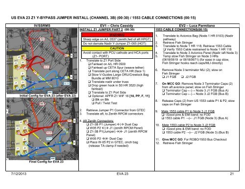
US EVA 23 Z1 Y-BYPASS JUMPER INSTALL (CHANNEL 3B) (00:30) / 1553 CABLE CONNECTIONS (00:15)<br />
IV/SSRMS EV1 – Chris Cassidy EV2 – Luca Parmitano<br />
INSTALL Z1 JUMPER PART 2 (00:30)<br />
1553 CABLE CONNECTIONS(00:15)<br />
Z1-005<br />
Initial Config for EVA 23 (after EVA 22)<br />
Z1-005<br />
WARNING<br />
Sharp edge on A/L 0537 (zenith,fwd of aft HPGT)<br />
Do not demate Nadir Y-Jumper Z1-005 (HOT)<br />
CAUTION<br />
Avoid contact with PCU cathode and HCA ports<br />
(Z1- PORT)<br />
1. Translate to Z1 Port Side<br />
Fairlead on A/L HR 0500<br />
Fairlead up CETA Spur (weave te<strong>the</strong>r)<br />
Translate port along CETA HR (face 1)<br />
Stow V-Guides Large ORU/Crewlock Bag<br />
Bundle at MM 8010<br />
Translate nadir under truss<br />
Drop green hook in S0 HR 3520 (high<br />
fairlead)<br />
Translate to Z1 Port Side<br />
Optional: APFR Z1 WIF 16 [10, PP, F, 11]<br />
Blk on Blk<br />
Pull / Twist Test<br />
2. Retrieve Jumper P1 Connector from GTEC<br />
3. Translate aft, to Zenith RPCM connectors<br />
4. Aft Zenith Connectors:<br />
Z1-3B P1 (Jumper) | Dust Cap<br />
W05 P2 | J1 (zenith RPCM Panel)<br />
Z1-3B P1(Jumper) | J1 (zenith RPCM<br />
Panel)<br />
W05 P2 | Dust Cap<br />
Place W-05 P2 in GTEC, cinch bag<br />
(release TA clamp if needed)<br />
1. Translate to Avionics Bag (Node 1 HR 0103) (Nadir<br />
pathway)<br />
2. Retrieve Fish Stringer<br />
3. Translate to Node 1 HR 118; Retrieve 1553 Cable<br />
Verify 1553 Cable restrained to Node 1 HR 118<br />
4. Translate to Node 3 Avionics Panel (Nadir /aft Node 3)<br />
5. Temp stow Fish Stringer on Node 3 HRs<br />
(0618/0619 or 0618/0671) (for ease in cap stow,<br />
Fish Stringer hooks reach caps/MLI directly)<br />
6. Remove Node 3 terminator MLI (2); stow on<br />
Fish Stringer<br />
J1 FGB J2 FGB<br />
7. On MCC GO: Remove Node 3 Terminator Caps (2)<br />
from aft avionics panel; stow on Fish Stringer<br />
Terminator Cap ←|→ Node 3 J1 FGB (Bus A)<br />
Terminator Cap ←|→ Node 3 J2 FGB (Bus B)<br />
8. Release Caps (2) from US 1553 cable P1 & P2; stow<br />
caps on Fish Stringer<br />
9. Mate 1553 cable P1 to Node 3 J1 FGB<br />
√Good pins & EMI band; no FOD<br />
1553 cable P1 →|← J1 FGB (Node 3) (Bus A)<br />
10. Mate 1553 cable P2 to Node 3 J2 FGB<br />
√Good pins & EMI band; no FOD<br />
1553 cable P2 →|← J2 FGB (Node 3) (Bus B)<br />
11. Give MCC GO: For ROBO/1553 Bus Checkout<br />
12. Retrieve Fish Stringer<br />
Final Config for EVA 23<br />
7/12/2013 EVA 23 21