Theory Building Tips
Theory Building Tips
Theory Building Tips

You also want an ePaper? Increase the reach of your titles
YUMPU automatically turns print PDFs into web optimized ePapers that Google loves.
Wiring Manual NEScaf April 2010 (August 2006)<br />
Switched Capacitor Audio Filter<br />
The NEScaf is a switched capacitor audio filter (acronym SCAF) built around a “building-block” type filter<br />
chip. The NEScaf will take the audio from any source (rig) and filter it to suit your listening…which is called a<br />
bandpass filter. The filter has two controls:<br />
1. the center frequency control allows the user to raise or lower the received frequency (the CW note) in the<br />
bandpass filter. The pitch can be set to a default value anywhere between 450-1000 Hz. range.<br />
2. the bandwidth control will vary the width of the received CW pitch from about 90 Hz to about 1500 Hz.<br />
The NEScaf is made up of four sections and it is recommended that builder constructs it in stages to test each as<br />
it is completed. The sections are:<br />
1. power supply: supplies raw power, 4.5v and 9v to the various stages<br />
2. audio amplifier: an LM386 IC audio amplifier<br />
3. clock generator: a 555 timer generating a clock pulse whose frequency divided by 100 will equal the<br />
center frequency for the filter. For example--if the 555 clock timer is generating 70 kHz, the center<br />
frequency will be 700 Hz.<br />
4. the SCAF IC chip. Your kit may contain an MF10, LMF100 or LTC1060 switched capacitor audio filter<br />
chip. When first introduced, the kit used the MF10. The most recent kits include the LTC1060. They<br />
are all pin-compatible with each other.<br />
<strong>Theory</strong><br />
The SCAF IC is made up of two CMOS active filters. The filters are easily configurable (low pass, band pass,<br />
notch, etc.), and builders are encouraged to experiment with them in other uses. We have configured both<br />
filters as Butterworth band pass filters, cascaded for optimum results. Butterworth filters have constant<br />
amplitude in the band pass region, while the cutoff knee is not be as sharp if the filter were configured as a<br />
Chebychev design. This is an acceptable tradeoff wanting constant volume out, regardless of the bandwidth or<br />
center frequency setting of the filter. Additional information about the National Semiconductor MF100 can be<br />
found in the application notes: http://www.national.com/apnotes/ActiveFilters.html. Though specific to the<br />
National family of ICs, the principles are applicable to all the versions of the filter IC used in the NEScaf..<br />
<strong>Building</strong> <strong>Tips</strong><br />
• As with any electronic kit, be sure the part you have in your hand is the part you want to solder onto the<br />
PC board. Check the markings for all components. We have gone through pains to make a very fine<br />
circuit board and supply you with quality components. We would like to stress the importance of<br />
special care in assembly and construction so that you will finish with a project we can all be proud of.<br />
• Work slowly and carefully, inserting a component, soldering it, clipping the leads, and finally inspecting<br />
each joint as you build your SCAF project. The vast majority of problems with kit projects is poor<br />
Wiring Manual NEScaf Page -1-<br />
New England QRP Club
solder joints. Heat first…count to 3 and then add solder. Apply a small amount of solder to the angle<br />
formed by the soldering tip, component lead and the circuit board. Do not remove the tip until solder<br />
has flowed completely around the circuit board pad and the component lead, and then slide the tip away<br />
from the board a short distance as you remove your iron. If you’re new to soldering, practice makes<br />
perfect. Try it.<br />
• Several parts for the NEScaf are sensitive to static discharge which include the integrated circuits (ICs).<br />
Take precautions to ground yourself prior to and while handling those sensitive parts by touching a<br />
ground point BEFORE handling them. Your body DOES hold a charge. DISCHARGE IT!<br />
• When describing orientation for part insertion, we assume that the builder is looking at the PC board<br />
with the “audio in” stencil to the builder’s left, and audio out to the right.<br />
• Due to parts availability, your 2 trimmer pots may have leads in a straight line or a triangle pattern. The<br />
leads should be carefully bent by inserting one “end” lead into the appropriate hole in the board, then<br />
gently twisting the body of the trimmer until the next lead lines up with its hole, then repeat for the third<br />
lead. Push down gently to seat the leads in their holes. The trimmer will not sit flush against the board,<br />
but rather above the board by about 1/8 to ¼ inch.<br />
Stage Ø: The Layout<br />
If IC sockets are used (highly recommended), insert them first. When inserting the socket for IC1, be<br />
careful to move it away from R1, R2, and R3 and toward R4 to make soldering easier later. Also check<br />
each joint on this socket very carefully (measure it with an ohm meter if needed) to ensure all pins are<br />
soldered well. A few minutes spent here may save anguished time later.<br />
Stage 1: The Power Supply<br />
Insert the following components (recommended in this order) onto the PC board. Foil side is down and stencil<br />
side is up. Insert components on the stencil side.<br />
[ ] R15 4.7k Ω (yellow, violet, red)<br />
[ ] C15 .33µF (334)<br />
[ ] R11 10 Ω (brown, black, black) (Don’t be confused with 10k! Use ohm meter to check.)<br />
[ ] C1 4.7µF electrolytic (observe polarity-short leg is negative)<br />
[ ] C2 4.7µF electrolytic (observe polarity-short leg is negative)<br />
[ ] C5 .1µF (104)<br />
[ ] R17 10k Ω (brown, black, orange)<br />
[ ] R18 10k Ω (brown, black, orange)<br />
[ ] C16 .1µF (104)<br />
[ ] C11 100µF electrolytic (observe polarity-short leg is negative)<br />
[ ] C19 .1µF (104)<br />
[ ] IC4 78L09 9v regulator - handle carefully and insert with correct orientation. Preform, if necessary<br />
Wiring Manual NEScaf Page -2-<br />
New England QRP Club
Prior to applying voltage power, check the resistance with an ohm meter between the Vcc (positive side of<br />
power) and GND (ground) connections. The resistance reading should indicate some amount of resistance<br />
other than a short (the exact value will depend on your meters impedance). If the reading is shorted (zero<br />
ohms), do not apply power but check all your work for solder bridges to ground!<br />
Connect a red wire to the Vcc input on the circuit board, and black wire to the ground pad. The length will be<br />
determined by the builder’s enclosure needs. Note also that the NEScaf has no reverse polarity protection, such<br />
as a diode, or fusing. Builders are advised to exercise great care when connecting power to the circuit.<br />
Connect power to the circuit board—Vcc (11.5 to 13.8 v). Nominal power of 12v. is expected for the NEScaf,<br />
but voltage down to 11.5 volts should still work. Positive voltage is connected to the red lead, and black lead<br />
negative (GND) is attached to the ground lead.<br />
Check the following pin connections to ground.<br />
[ ] IC1 pin 6 = 9vdc<br />
[ ] IC1 pin 7 = 9vdc<br />
[ ] IC1 pin 8 = 9vdc<br />
[ ] IC1 pin 5 = 4.5vdc<br />
[ ] IC1 pin 12 = 4.5vdc<br />
[ ] IC1 pin 15 = 4.5vdc<br />
[ ] IC1 pin 16 = 4.5vdc<br />
[ ] IC2 pin 6 = Vcc supplied to board<br />
[ ] IC3 pin 4 = 9vdc<br />
Turn off the power and move on to stage two—audio amplifier.<br />
Stage 2: Audio Amplifier<br />
Insert the following components—NOTE: C3 has been changed from 10µF to 100µF. Due to it’s slightly<br />
larger size, it is recommended to install the components in this order. C3 may sit slightly above the<br />
board due to it’s lead spacing. This will not affect filter performance.<br />
[ ] C18 4700pf (472)<br />
[ ] R20 15k Ω (brown, green, orange)<br />
[ ] C9 1µF (105) This is a tantalum cap and is polarized. The hard to see black stripe points to the<br />
positive lead. Insert with the positive lead closest to IC1. Do not clip the positive lead on<br />
this capacitor after soldering, as it will be used to test the circuit when done.<br />
[ ] C10 .01µF (103)<br />
[ ] C12 .1µF (104)<br />
[ ] R12 10 Ω (brown, black, black) (Don’t be confused with 10k! Use ohm meter to check.)<br />
[ ] C3 100µF electrolytic (was 10µF - observe polarity-short leg is negative)<br />
[ ] R14 10k Ω trimmer pot ( you may need to gently move the legs to position this on the board.)<br />
[ ] IC2 LM386 – Makes sure IC pins are parallel to each other when inserting into socket, if used.<br />
Pin one is marked by a circular indentation on the top of the IC package and it should be<br />
placed toward the center of the circuit board.<br />
**If you have an audio oscillator near by, connect it to the positive lead of C9, farthest away from IC1. Should<br />
an audio oscillator not be available, any audio source will do (audio from another rig for instance). Be sure to<br />
ground the audio oscillator or audio source onto the PCB. Connect a speaker or low impedance headphones<br />
Wiring Manual NEScaf Page -3-<br />
New England QRP Club
etween the ‘audio out’ connection and ground; apply power. You should hear an audio tone. Now apply the<br />
same audio tone to pin 19 on IC1, (IC 1 MP10/100 should not be inserted yet). Audio should be heard in the<br />
speaker. Adjust R14 to ensure it varies the volume and set it to approximately ¼ turn clockwise (cw).<br />
Once the SCAF filter is complete, R14 will adjust the volume output for the filter. We chose a design which<br />
would provide for unity gain, inasmuch, when the filter is turned on or off, the volume output does not change.<br />
If SW1 is wired as recommended, the NEScaf may be left inline between the rig of choice and the user’s<br />
speaker or headphones, and audio will bypass the NEScaf to the output when the SCAF filter is off. Some<br />
builders may choose to replace R14 with a panel mounted potentiometer to allow controlling the NEScaf<br />
volume.<br />
Stage 3: Clock Generator<br />
Insert the following components--<br />
[ ] C6 .001 µF (102) - This is an NPO capacitor and is critical in the design. Substituting a non-<br />
NPO capacitor may allow the filter center frequency to shift. The cap supplied is an “axial”<br />
type, leads extending from each end. One lead can be gently bent back over the body of the<br />
cap, and the cap mounted vertically on the board. This may be easier than bending the leads<br />
to fit the hole spacing on the board..<br />
[ ] C8 .01µF(103)<br />
[ ] C7 1µF (105) Tantalum - observe polarity with positive away from IC1.<br />
[ ] R8 2k Ω (red, black, red)<br />
[ ] R9 10k Ω pot (perform component leads to positioned onto PC board)<br />
[ ] IC3 555 timer IC. Makes sure pins are parallel to each other when inserting into socket, if used.<br />
[ ] R10 10k Ω off-board potentiometer with detent.. Center connection (wiper) connects to R10_w<br />
and left hand connection, looking from front, connects to R10 on PC board. This will cause<br />
cw (clockwise) turning to correspond decreasing resistance, and as a result increasing<br />
frequency. The right tab and center wiper tab on the pot are connected together with a short<br />
piece of wire.<br />
Applying power should produce about 70kHz on pins 10 and 11 of IC1 (without MF100 IC chip inserted). This<br />
should be easily detected with a scope or a frequency counter. The 555 clock will be about 9v peak-to-peak so<br />
be careful connecting the leads to a frequency counter that it does not overload or damage the input.<br />
A careful observation will show that there are two potentiometers setting the frequency of the oscillator and by<br />
extension, the center frequency of the band pass of the filter. The frequency of the IC-555 is 100 times the<br />
center frequency of the filter. A frequency of 70 kHz for the IC-555 circuit will result in a center frequency of<br />
700 Hz. for the filter overall. The on-board trimmer pot is used to allow the center frequency, selected by the<br />
user, to correspond to the detent position of the off-board potentiometer. Further discussion follows for setting<br />
the center frequency once the SCAF filter is complete.<br />
Stage 4 The Scaf Filter<br />
Insert the following components--<br />
[ ] R2 27k Ω (red, violet, orange)-- red and orange are easy to confuse; measure with an ohm meter.<br />
[ ] R1 2.7k Ω (red, violet, red)<br />
[ ] R3 27k Ω (red, violet, orange)<br />
[ ] R5 27k Ω (red, violet, orange)<br />
[ ] R4 2.7k Ω (red, violet, red)<br />
Wiring Manual NEScaf Page -4-<br />
New England QRP Club
[ ] R6 27k Ω (red, violet, orange)<br />
[ ] C17 1µF (105)<br />
[ ] R7 Panel mounted, dual gang 50k Ω potentiometer-Take care that the wiper<br />
connection (middle pin on pot) goes to the designated W connections on<br />
circuit board. The circuit board is labeled R7a and R7a_w for the first<br />
'gang' or section, and R7b and R7b_w for the second. The W stands for wiper<br />
(middle tab on each potentiometer section). Looking at the front of the<br />
potentiometers, connect the center tab of each gang to the correct circuit<br />
board location labeled W. The center tab (wiper) and the left tab are<br />
connected together with a short piece of wire. Next, connect the right tab<br />
of each gang to the correct circuit board location for each gang( R7a and<br />
R7b). So, if you connect the center tab (wiper) of the pot section closest<br />
to the shaft to R7a_w, then connect the right tab of that same pot section<br />
to R7a. Twist the two leads to each pot separately as it makes it easier to<br />
keep track on the PCB. Some components already mounted on the circuit board<br />
might ‘hide’ the W so be familiar with the PC board layout.<br />
[ ] IC1 MF10, LMF100 or LTC1060 IC chip Make sure pins are parallel to each other when inserting (if<br />
using sockets) and pin 1 is toward the top of the PC board.<br />
The SCAF filter at this point could be connected to an audio generator at the SCAF audio input point. Connect<br />
a small speaker to the audio output (using the appropriate grounds); connect power; the tone should be audible<br />
to your ear. If there is no audio, turn the bandwidth potentiometer (double pot) extreme left or right, and then<br />
turn the center frequency pot to hear audio At this point, you should hear an audio signal..<br />
Stage 5 Final Things<br />
The NEScaf should now be fully populated. Some panel connections need to be made.<br />
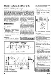
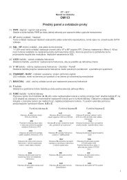
• DPDT SW1: This switch is two switches in parallel: one to control power to the NEScaf and the other to<br />
control audio to the headphones. (See below.) Section A controls power, with the center connection<br />
coming from the battery to the unit. The lower contact of section A will be connected to Vcc on the PC<br />
board. The upper contact of section A is not connected--nc. Section B controls audio with the center tab<br />
from the audio source—the rig. The lower connection of section B will connect to ‘audio in’ on the<br />
NEScaf circuit board. The upper connection of section B will go to the ‘audio out’ on the NEScaf<br />
connector--to the headphones. The ‘audio out’ of the circuit board should also be connected to the ‘audio<br />
out’ connector to the headphones. Connected this way, and when power is on, ‘audio in’ is routed from<br />
the rig through the switch to the audio input of the NEScaf. When power is off, ‘audio in’ is routed<br />
directly to the ‘audio out’ connector--the headphones.<br />
Figure 1 SWITCH #1 DPDT<br />
Review your wiring.<br />
Wiring Manual NEScaf Page -5-<br />
New England QRP Club
[ ] Mount audio connectors: as desired.<br />
[ ] Mount LED power indicator.<br />
• LED POWER INDICATOR. An LED is provided in the standard kit and can be connected to the PC<br />
board. Observe polarity (shorter lead to circuit board ground). The LED can be panel mounted, board<br />
mounted, or omitted altogether. It will light when DC power is on and the SCAF is functional.<br />
• AUDIO CONNECTORS: Two portable radio size, female audio connectors are supplied in the<br />
optional connector kit. One audio connector soldered to the audio input of the DPDT switch and the<br />
other audio connector is soldered to the ‘audio output’ on the NEScaf PC board. Ground connections<br />
should be made to the appropriate points on the circuit board.<br />
• POWER CONNECTION: A standard 2.1mm x 5.5mm power connector is provided in the optional<br />
connector kit. Note that often the GND is connected to the outside pin and positive to the center pin.<br />
Also note that no fusing or reverse power protection diode is provided with the NEScaf. Caveat builder<br />
and be careful!<br />
Once the filter has all the appropriate connections, the two on board potentiometers can be adjusted for<br />
optimal use:<br />
• R10 adjusts the center frequency of the filter. Connect the NEScaf filter to the audio output of your<br />
favorite rig, and set the rig to produce its side tone. Set the bandwidth of the NEScaf filter to its widest<br />
position. Now, set the center frequency panel potentiometer to its detent position. The side tone should<br />
be heard on the output speaker or headphones. Slowly narrow the bandwidth with the BW (bandwidth)<br />
potentiometer, and adjust R10 to keep the side tone audible. When the bandwidth is its narrowest<br />
setting, peak the audio heard with R10. The filter is now centered for the rig of choice. The NEScaf can<br />
also be used as a ‘zero beat’ tool at its narrowest setting.<br />
• R14 adjusts the audio volume out from the NEScaf. If SW1 is wired as mentioned above, sound from<br />
the rig should be heard directly from the rig when the NEScaf is off, and the sound from the rig should<br />
be filtered and audible when the NEScaf is on. We have found it convenient to adjust R14 so that the<br />
audio volume is the same whether the filter is on or off. Easier on your ears in the long run.<br />
What if the SCAF does not work. [Troubleshooting] Suggestions…<br />
• Take a break and come back to it when you’re ready. Other hams have built the SCAF filter and have it<br />
working. You can too!<br />
• Reheat every connection on the bottom of the board to be certain you do not have a cold solder joint.<br />
Unfortunately, however, cold solder joints or a solder bridge are two of the most common mistakes in kit<br />
building. Be careful and work slowly and you’ll be rewarded! Don’t over do it with the solder.<br />
• Recheck the voltages on the ICs and reread the resistor placement for any misallocated parts.<br />
• Check each stage for proper operation one by one:<br />
• Power is okay? Voltages accurate?<br />
• With IC1 removed, does the audio amp work properly?<br />
• With IC1 removed, does the 555 clock generator work properly?<br />
• Check each of the connections from IC1 and carefully reheat if necessary.<br />
Beyond this builders have two resources: There is a forum for discussing problems (and accolades) on<br />
www.newenglandqrp.org. For problems beyond reason, email NEScafhelp@newenglandqrp.org. We do ask<br />
that email be sent there only after the forum has been tried first.<br />
Wiring Manual NEScaf Page -6-<br />
New England QRP Club
Parts List<br />
NT1U - v3.1 24 Aug 06<br />
K1LGQ 23Aug06<br />
Revised K1LGQ 03March08<br />
Revised N1RX 28April2010<br />
Part<br />
C1<br />
C2<br />
C3<br />
C5<br />
C6<br />
C7<br />
C8<br />
C9<br />
C10<br />
C11<br />
C12<br />
C15<br />
C16<br />
C17<br />
C18<br />
C19<br />
Value<br />
4.7µF 50v electrolytic<br />
4.7µF 50v electrolytic<br />
100µF 25v electrolytic<br />
.1µF<br />
.001µF (NPO)<br />
1µF tantalum<br />
.01µF<br />
1µF Tantalum<br />
.01µF<br />
100µF 25v electrolytic<br />
.1µF<br />
.33µF<br />
.1µF<br />
1µF Tantalum<br />
4700pf<br />
.1µF<br />
NOTE: C4, C13, and C14 were removed<br />
during design revisions.<br />
Part<br />
R1<br />
R2<br />
R3<br />
R4<br />
R5<br />
R6<br />
R7<br />
R8<br />
R9<br />
R10<br />
R11<br />
R12<br />
R14<br />
R15<br />
R17<br />
R18<br />
R20<br />
Value<br />
2.7k Ω (all resistors 1/4w)<br />
27k Ω<br />
27k Ω<br />
2.7k Ω<br />
27k Ω<br />
27k Ω<br />
Dual gang 50k Ω panel mounted<br />
potentiometers<br />
2k Ω<br />
10k Ω on board trimmer potentiometer<br />
10k Ω panel mounted potentiometer, with<br />
center detent<br />
10 Ω<br />
10 Ω<br />
10k Ω on board trimmer potentiometer<br />
4.7k Ω<br />
10k Ω<br />
10k Ω<br />
15k Ω<br />
NOTE: R13, R16, and R19 were removed<br />
during design revisions.<br />
Wiring Manual NEScaf Page -7-<br />
New England QRP Club
IC1<br />
IC2<br />
IC3<br />
IC4<br />
LED<br />
SW1<br />
MF10, LMF100 or LTC1060 SCAF<br />
LM386 Op amp<br />
555 timer<br />
78L09 regulator<br />
Green<br />
DPDT panel mounted switch<br />
Not included in basic kit:<br />
Audio connectors, (optional kit)<br />
Power connectors, (optional kit)<br />
IC sockets: 1 - 20 pin, 2 ea. 8 pins<br />
Enclosure<br />
Wiring Manual NEScaf Page -8-<br />
New England QRP Club
Wiring Manual NEScaf Page -9-<br />
New England QRP Club
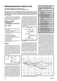
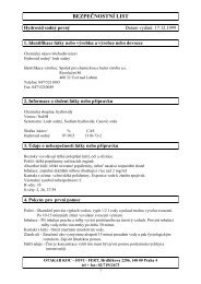
Stencil Layout<br />
Wiring Manual NEScaf Page -10-<br />
New England QRP Club