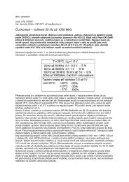
Theory Building Tips
Theory Building Tips
Theory Building Tips

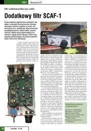
Create successful ePaper yourself
Turn your PDF publications into a flip-book with our unique Google optimized e-Paper software.
solder joints. Heat first…count to 3 and then add solder. Apply a small amount of solder to the angle<br />
formed by the soldering tip, component lead and the circuit board. Do not remove the tip until solder<br />
has flowed completely around the circuit board pad and the component lead, and then slide the tip away<br />
from the board a short distance as you remove your iron. If you’re new to soldering, practice makes<br />
perfect. Try it.<br />
• Several parts for the NEScaf are sensitive to static discharge which include the integrated circuits (ICs).<br />
Take precautions to ground yourself prior to and while handling those sensitive parts by touching a<br />
ground point BEFORE handling them. Your body DOES hold a charge. DISCHARGE IT!<br />
• When describing orientation for part insertion, we assume that the builder is looking at the PC board<br />
with the “audio in” stencil to the builder’s left, and audio out to the right.<br />
• Due to parts availability, your 2 trimmer pots may have leads in a straight line or a triangle pattern. The<br />
leads should be carefully bent by inserting one “end” lead into the appropriate hole in the board, then<br />
gently twisting the body of the trimmer until the next lead lines up with its hole, then repeat for the third<br />
lead. Push down gently to seat the leads in their holes. The trimmer will not sit flush against the board,<br />
but rather above the board by about 1/8 to ¼ inch.<br />
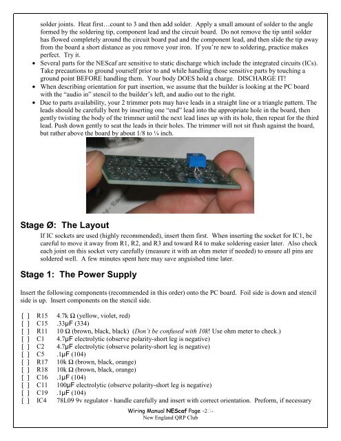
Stage Ø: The Layout<br />
If IC sockets are used (highly recommended), insert them first. When inserting the socket for IC1, be<br />
careful to move it away from R1, R2, and R3 and toward R4 to make soldering easier later. Also check<br />
each joint on this socket very carefully (measure it with an ohm meter if needed) to ensure all pins are<br />
soldered well. A few minutes spent here may save anguished time later.<br />
Stage 1: The Power Supply<br />
Insert the following components (recommended in this order) onto the PC board. Foil side is down and stencil<br />
side is up. Insert components on the stencil side.<br />
[ ] R15 4.7k Ω (yellow, violet, red)<br />
[ ] C15 .33µF (334)<br />
[ ] R11 10 Ω (brown, black, black) (Don’t be confused with 10k! Use ohm meter to check.)<br />
[ ] C1 4.7µF electrolytic (observe polarity-short leg is negative)<br />
[ ] C2 4.7µF electrolytic (observe polarity-short leg is negative)<br />
[ ] C5 .1µF (104)<br />
[ ] R17 10k Ω (brown, black, orange)<br />
[ ] R18 10k Ω (brown, black, orange)<br />
[ ] C16 .1µF (104)<br />
[ ] C11 100µF electrolytic (observe polarity-short leg is negative)<br />
[ ] C19 .1µF (104)<br />
[ ] IC4 78L09 9v regulator - handle carefully and insert with correct orientation. Preform, if necessary<br />
Wiring Manual NEScaf Page -2-<br />
New England QRP Club