Quick Selection
Quick Selection
Quick Selection

You also want an ePaper? Increase the reach of your titles
YUMPU automatically turns print PDFs into web optimized ePapers that Google loves.
Technical data and ordering<br />
Type<br />
HE 0.5<br />
HE 1.0<br />
HE 1.5<br />
HE 4.0<br />
HE 8.0<br />
Solder connection ODF<br />
Liquid line Suction line Code no.<br />
in. mm in. mm<br />
6 12 015D0001<br />
1<br />
/ 1<br />
4<br />
/ 2<br />
015D0002<br />
10 16 015D0003<br />
3<br />
/ 5<br />
8<br />
/ 8<br />
015D0004<br />
12 18 015D0005<br />
1<br />
/ 3<br />
2<br />
/ 4<br />
015D0006<br />
12 28 015D0007<br />
1<br />
/ 2<br />
1 1 / 8<br />
015D0008<br />
16 42 015D0009<br />
5<br />
/ 8<br />
1 5 / 8<br />
015D0010<br />
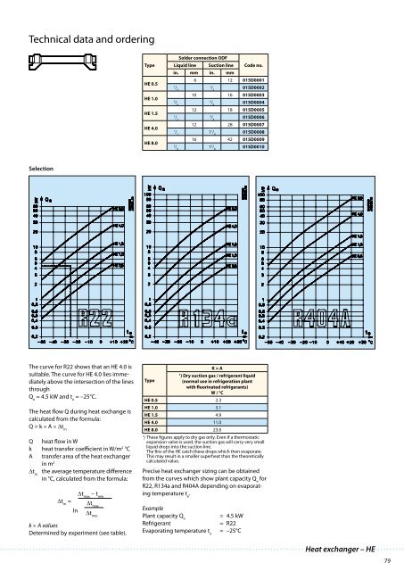
<strong>Selection</strong><br />
The curve for R22 shows that an HE 4.0 is<br />
suitable. The curve for HE 4.0 lies immediately<br />
above the intersection of the lines<br />
through<br />
Q e<br />
= 4.5 kW and t e<br />
= –25°C.<br />
The heat flow Q during heat exchange is<br />
calculated from the formula:<br />
Q = k × A × Δt m<br />
Q heat flow in W<br />
k heat transfer coefficient in W/m 2 °C<br />
A transfer area of the heat exchanger<br />
in m 2<br />
Δt m<br />
the average temperature difference<br />
in °C, calculated from the formula:<br />
Δt max.<br />
– t min.<br />
Δt m<br />
= Δt max.<br />
ln<br />
Δt min.<br />
k × A values<br />
Determined by experiment (see table).<br />
Precise heat exchanger sizing can be obtained<br />
from the curves which show plant capacity Q e<br />
for<br />
R22, R134a and R404A depending on evaporating<br />
temperature t e<br />
.<br />
Example<br />
Plant capacity Q e<br />
Refrigerant<br />
Evaporating temperature t e<br />
K × A<br />
1<br />
) Dry suction gas / refrigerant liquid<br />
Type<br />
(normal use in refrigeration plant<br />
with fluorinated refrigerants)<br />
W / °C<br />
HE 0.5 2.3<br />
HE 1.0 3.1<br />
HE 1.5 4.9<br />
HE 4.0 11.0<br />
HE 8.0 23.0<br />
1<br />
) These figures apply to dry gas only. Even if a thermostatic<br />
expansion valve is used, the suction gas will carry very small<br />
liquid drops into the suction line.<br />
The fins of the HE catch these drops which then evaporate.<br />
This may result in a smaller superheat than the theoretically<br />
calculated value.<br />
= 4.5 kW<br />
= R22<br />
= –25°C<br />
Heat exchanger – HE<br />
79