MINI MCR-SL-UI-REL(-SP) - Onlinecomponents.com
MINI MCR-SL-UI-REL(-SP) - Onlinecomponents.com
MINI MCR-SL-UI-REL(-SP) - Onlinecomponents.com

Create successful ePaper yourself
Turn your PDF publications into a flip-book with our unique Google optimized e-Paper software.
<strong>MINI</strong> <strong>MCR</strong>-<strong>SL</strong>-<strong>UI</strong>-<strong>REL</strong>(-<strong>SP</strong>)<br />
Configurable Threshold Value Switch<br />
INTERFACE<br />
Data Sheet<br />
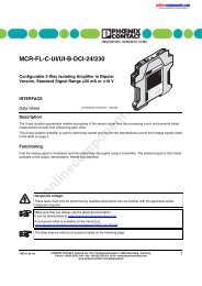
Description<br />
The <strong>MINI</strong> <strong>MCR</strong>-<strong>SL</strong>-<strong>UI</strong>-<strong>REL</strong>(-<strong>SP</strong>) configurable 3-way<br />
threshold value switch is used to control and monitor analog<br />
standard signals.<br />
On the input side, the 0 mA ... 20 mA or 0 V … 10 V analog<br />
standard signals can be set via DIP switches. A relay with<br />
PDT contact is available on the output side. The switching<br />
thresholds are set via a potentiometer.<br />
The DIP switches located on the side of the housing have<br />
the following functions:<br />
– Configuration of the switching hysteresis<br />
– Configuration of the operating and closed circuit current<br />
behavior<br />
– Setting of relay pickup times<br />
– Setting of dropout delay<br />
© PHOENIX CONTACT - 08/2006<br />
The relay status is indicated by a yellow LED on the front of<br />
the housing.<br />
The power supply (19.2 V DC ... 30 V DC) can be supplied<br />
via connection terminal blocks "7" and "8" on the modules<br />
or in conjunction with the DIN rail connector (see Figure 5<br />
on page 5). Please refer to Section "Power Supply" on<br />
page 6.<br />
online<strong>com</strong>ponents.<strong>com</strong><br />
Make sure you always use the latest documentation.<br />
It can be downloaded at www.download.phoenixcontact.<strong>com</strong>.<br />
A conversion table is available on the Internet at<br />
www.download.phoenixcontact.<strong>com</strong>/general/7000_en_00.pdf.<br />
This data sheet is valid for all products listed on the following page:<br />
102132_02_en PHOENIX CONTACT GmbH & Co. KG • 32823 Blomberg • Germany<br />
1<br />
Phone: +49 - 52 35 - 30 0 • Fax: +49 - 52 35 - 34 12 00 • www.phoenixcontact.<strong>com</strong><br />
www.phoenixcontact.<strong>com</strong>/salesnetwork
<strong>MINI</strong> <strong>MCR</strong>-<strong>SL</strong>-<strong>UI</strong>-<strong>REL</strong>(-<strong>SP</strong>)<br />
Ordering Data<br />
Threshold Value Switch<br />
Description Type Order No. Pcs./Pck.<br />
Configurable threshold value switch with screw connection <strong>MINI</strong> <strong>MCR</strong>-<strong>SL</strong>-<strong>UI</strong>-<strong>REL</strong> 2864480 1<br />
Configurable threshold value switch with spring-cage connection <strong>MINI</strong> <strong>MCR</strong>-<strong>SL</strong>-<strong>UI</strong>-<strong>REL</strong>-<strong>SP</strong> 2864493 1<br />
Accessories<br />
Description Type Order No. Pcs./Pck.<br />
DIN rail connector ME 6,2 TBUS-2 1,5/5-ST-3,81 GN 2869728 1<br />
Power terminal block with screw connection <strong>MINI</strong> <strong>MCR</strong>-<strong>SL</strong>-PTB 2864134 1<br />
Power terminal block with spring-cage connection <strong>MINI</strong> <strong>MCR</strong>-<strong>SL</strong>-PTB-<strong>SP</strong> 2864147 1<br />
System power supply unit (not for zone 2) <strong>MINI</strong>-SYS-PS-100-240AC/24DC/1.5 2866983 1<br />
Technical Data<br />
Input (see Figure 1, 7) I IN U IN<br />
Input signal range<br />
0 mA ... 20 mA;<br />
configurable (DIP switches)<br />
online<strong>com</strong>ponents.<strong>com</strong><br />
0 V ... 10 V;<br />
configurable (DIP switches)<br />
Maximum permissible input level 5 V DC 30 V DC<br />
Input signal 100 mA, maximum 30 V, maximum<br />
Input resistance 50 Ω > 100 kΩ<br />
Specification of the switching point<br />
Relay Output (see Figure 1, 1)<br />
Status indicators<br />
Contact type<br />
Yellow LED<br />
<strong>SP</strong>DT contact<br />
Contact material (hard gold-plated) AgSnO 2<br />
Switching voltage<br />
250 V AC, maximum<br />
Switching current<br />
Hysteresis<br />
Operating and closed circuit current behavior<br />
2 A, maximum<br />
Via 25-speed potentiometer<br />
0.1%, 1%, 2.5%, 5%; configurable (DIP switches)<br />
Switchable (DIP switches)<br />
Relay pickup/relay dropout delay 0 s, 1 s, 2 s, 3 s, 4 s, 6 s, 8 s, 10 s;<br />
configurable (DIP switches)<br />
General Data<br />
Supply voltage<br />
19.2 V DC ... 30 V DC<br />
Current consumption at 24 V DC<br />
< 14 mA<br />
Power consumption at 24 V DC<br />
< 330 mW<br />
Final value linearity error < 0.05%<br />
Temperature coefficient<br />
< 0.02%/K<br />
Step response (10% ... 90%)<br />
35 ms<br />
Test voltage (input/supply)<br />
1.5 kV, 50 Hz, 1 minute<br />
Error messages<br />
Red LED<br />
Degree of protection<br />
IP20<br />
Ambient temperature range<br />
Operation<br />
Storage<br />
Dimensions (W x H x D)<br />
-20°C ... +65°C<br />
-40°C ... +85°C<br />
6.2 mm x 93.1 mm x 102.5 mm<br />
Conductor Cross Section 0.2 ... 2.5 mm 2<br />
Stripping length<br />
Screw connection<br />
Spring-cage connection<br />
Housing version<br />
12 mm<br />
8 mm<br />
Polybutylene terephthalate PBT, green<br />
102132_02_en PHOENIX CONTACT 2
No.2961121<br />
<strong>MINI</strong> <strong>MCR</strong>-<strong>SL</strong>-<strong>UI</strong>-<strong>REL</strong>(-<strong>SP</strong>)<br />
Tests/Approvals<br />
Conformity assessment according to EN 60079-15<br />
Electromagnetic <strong>com</strong>patibility<br />
Shipbuilding<br />
UL approvals<br />
Conformance With EMC Directive 89/336/EEC and Low Voltage Directive 73/23/EEC<br />
Noise Immunity Test According to EN 61000-6-2 1<br />
Structure<br />
X II 3G Ex nAC IIC T4 X<br />
c <strong>com</strong>pliant<br />
Germanischer Lloyd F<br />
U<br />
PROCESS CONTROL EQ<strong>UI</strong>PMENT FOR HAZARDOUS<br />
LOCATIONS<br />
LISTED<br />
31ZN<br />
Class I, Zone 2, AEx nC IIC T6 and Class I, Zone 2, Ex nC IIC T6<br />
A) This equipment is suitable for use in Class I, Zone 2, Groups IIC<br />
or non-hazardous locations only.<br />
B) Warning - explosion hazard - substitution of <strong>com</strong>ponents may impair<br />
suitability for Class 1, Zone 2.<br />
C) Warning - explosion hazard - do not disconnect equipment unless power<br />
has been switched off or the area is known to be non-hazardous.<br />
Electrostatic discharge (ESD) EN 61000-4-2 Criterion B 2<br />
Electromagnetic HF field EN 61000-4-3 Criterion A 3<br />
Fast transients (burst) EN 61000-4-4 Criterion B 4<br />
Surge current load (surge) EN 61000-4-5 Criterion B 4<br />
Conducted interference EN 61000-4-6 Criterion A 3<br />
Noise Emission Test According to EN 610006-4<br />
Noise emission of housing EN 55011 5 Class A 6<br />
1 EN 61000 corresponds to IEC 1000<br />
2 Criterion B: Appropriate measures must be taken to prevent electrostatic discharge.<br />
3 Criterion A: Normal operating behavior within the specified limits.<br />
4 Criterion B: Temporary adverse effects on the operating behavior, which the device corrects automatically.<br />
5 EN 55011 corresponds to CI<strong>SP</strong>R 11<br />
6 Class A: Industrial application<br />
7<br />
8<br />
5<br />
6<br />
1 Relay output<br />
2 Transparent cover<br />
3 LED: Status indicators<br />
4 LED: Error messages<br />
5 Potentiometer for adjustment<br />
6 Groove for ZBF 6 Zack marker strip<br />
7 Input: Standard signals<br />
8 Supply voltage<br />
9 Connection option for DIN rail connector<br />
10 Universal snap-on foot for EN DIN rails<br />
11 DIP switch S1<br />
online<strong>com</strong>ponents.<strong>com</strong><br />
1<br />
on<br />
S1<br />
off<br />
<strong>MINI</strong> <strong>MCR</strong>-<strong>SL</strong>-<strong>UI</strong>-<strong>REL</strong> Ord.-No.: 28 64 48 0<br />
Threshold Value Switch<br />
Input: 0...10V, 0...20mA<br />
Out: 1 PDT<br />
Test voltage: 1,5kV, 50 Hz, 1min.<br />
Amb. Temp.: -20°...+65°C / -4°...+149°F<br />
In + 5 +<br />
IN<br />
In - GND 1 6 -<br />
19,2...30VDC 7+<br />
POWER<br />
GND 2 8 -<br />
c<br />
Serial No. XXXXXXXX<br />
3<br />
4<br />
2<br />
<strong>MINI</strong> <strong>MCR</strong>-<strong>SL</strong>-<strong>UI</strong>-<strong>REL</strong><br />
1 NC<br />
2<br />
14<br />
+3 11<br />
OUT<br />
- 4 12<br />
PROCESS CONTROL<br />
EQ<strong>UI</strong>PMENT<br />
FOR HAZARDOUS<br />
LOCATIONS 31ZN<br />
Cl. I, Div. 2,<br />
Grps. A,B,C,D T5<br />
1<br />
!<br />
0<br />
9<br />
Figure 1<br />
Structure<br />
102132_02_en PHOENIX CONTACT 3
<strong>MINI</strong> <strong>MCR</strong>-<strong>SL</strong>-<strong>UI</strong>-<strong>REL</strong>(-<strong>SP</strong>)<br />
Installation<br />
Cables may only be snapped on and connected in potentially explosive areas when the power is<br />
disconnected.<br />
Screw Connection<br />
Spring-Cage Connection<br />
2<br />
1<br />
Figure 2<br />
<strong>MINI</strong> <strong>MCR</strong>-<strong>SL</strong>-<strong>UI</strong>-<strong>REL</strong><br />
Figure 3<br />
The assignment of the connection terminal blocks is shown in Figure 4.<br />
Block Diagram<br />
<strong>MINI</strong> <strong>MCR</strong>-<strong>SL</strong>-<strong>UI</strong>-<strong>REL</strong>-<strong>SP</strong><br />
Installation and startup must only be carried out by qualified personnel. The relevant country-specific<br />
regulations (e.g., VDE, DIN) must also be observed.<br />
Notes on explosion protection:<br />
The device is a category 3 item of electrical equipment. Follow the instructions provided during installation. The<br />
device must be installed in housing with IP54 protection according to EN 60529. The specified limits for<br />
mechanical strain or thermal loads for the device must not be exceeded. Only devices suitable for operation in<br />
zone 2 potentially explosive areas may be connected. Repairs must not be carried out by the user.<br />
7<br />
1 7 1 #<br />
/ , $<br />
)<br />
,<br />
+<br />
online<strong>com</strong>ponents.<strong>com</strong><br />
, +<br />
14 12<br />
11<br />
<br />
!<br />
"<br />
+<br />
"<br />
<br />
<br />
1<br />
9<br />
, +<br />
ME 6,2 TBUS-2...<br />
%<br />
&<br />
7 * <br />
/ ,<br />
8<br />
Figure 4<br />
Block diagram<br />
The <strong>MINI</strong> Analog module can be snapped onto all 35 mm DIN rails according to EN 60715.<br />
102132_02_en PHOENIX CONTACT 4
<strong>MINI</strong> <strong>MCR</strong>-<strong>SL</strong>-<strong>UI</strong>-<strong>REL</strong>(-<strong>SP</strong>)<br />
Use of the ME 6,2 TBUS-2 1,5/5-ST-3,81 GN DIN Rail Connector (Order No. 2869728)<br />
Observe the direction of the <strong>MINI</strong> Analog<br />
module and DIN rail connector when snapping<br />
into position:<br />
Snap-on foot (Figure 5, D, 10) below and<br />
connector (Figure 5, C, 12) left.<br />
• First, insert the DIN rail connector in the DIN rail to<br />
bridge the power supply (see Figure 5).<br />
) * +<br />
D<br />
E<br />
0<br />
Figure 5 Assembly/removal<br />
online<strong>com</strong>ponents.<strong>com</strong><br />
"<br />
102132_02_en PHOENIX CONTACT 5
<strong>MINI</strong> <strong>MCR</strong>-<strong>SL</strong>-<strong>UI</strong>-<strong>REL</strong>(-<strong>SP</strong>)<br />
Power Supply<br />
Configuration<br />
Supply via the <strong>MINI</strong> Analog Module<br />
Where the total current consumption of the aligned <strong>MINI</strong><br />
Analog modules does not exceed 400 mA, the power can<br />
be supplied directly at the connection terminal blocks of one<br />
<strong>MINI</strong> Analog module. A 400 mA fuse should be connected.<br />
Supply Using a Power Terminal Block<br />
The <strong>MINI</strong> <strong>MCR</strong>-<strong>SL</strong>-PTB power terminal block (Order No.<br />
2864134) or the <strong>MINI</strong> <strong>MCR</strong>-<strong>SL</strong>-PTB-<strong>SP</strong> power terminal<br />
block (Order No. 2864147), which are the same shape, are<br />
used to supply the supply voltage to the DIN rail connector.<br />
A 2 A fuse should be connected.<br />
Supply Using System Power Supply Unit<br />
(Not for Zone 2)<br />
The <strong>MINI</strong>-SYS-PS-... system power supply unit (Order No.<br />
2866983) with 1.5 A output current connects the DIN rail<br />
connector to the supply voltage and can thus be used to<br />
supply several <strong>MINI</strong> Analog modules from the mains.<br />
Diagnostics<br />
Never connect the supply voltage directly to<br />
the DIN rail connector.<br />
It is not permitted to draw power from the<br />
DIN rail connector or from individual <strong>MINI</strong><br />
Analog modules.<br />
The yellow LED on the front of the device (3 in Figure 1 on<br />
page 3) indicates that voltage is applied to the PDT relay<br />
coil, i.e., that the relay has switched.<br />
The red LED on the front of the device (4 in Figure 1 on<br />
page 3) indicates the following error states:<br />
– LED ON: Measured value overrange > 102.5%<br />
– LED flashing: Module faulty<br />
Setting the Switching Thresholds<br />
The potentiometer 5, which can be used to set the<br />
switching thresholds, is located under the transparent<br />
cover.<br />
Figure 6<br />
Electrostatic discharge<br />
The module contains <strong>com</strong>ponents that can be<br />
damaged or destroyed by electrostatic<br />
discharge. When handling this module, observe<br />
the necessary safety precautions against<br />
electrostatic discharge (ESD) according to<br />
EN 61340-5-1 and EN 61340-5-2.<br />
Potentiometer and DIP switches<br />
DIP Switches<br />
DIP switch S1 (! in Figure 6) can be used to specify the<br />
input signal range, switching hysteresis, the relay pickup/<br />
relay dropout delay, and to switch between operating<br />
current/closed circuit current behavior.<br />
DIP S1<br />
Input<br />
1 2<br />
0 V ... 10 V<br />
• • 0 mA ... 20 mA<br />
• = ON<br />
online<strong>com</strong>ponents.<strong>com</strong><br />
<strong>MINI</strong> <strong>MCR</strong>-<strong>SL</strong>-<strong>UI</strong>-<strong>REL</strong><br />
5<br />
1<br />
on<br />
S1<br />
off<br />
!<br />
Ord.-No.: 28 64 48 0<br />
Switch<br />
DIP S1<br />
Switching Hysteresis<br />
3 4<br />
0.1%<br />
• 1.0%<br />
• 2.5%<br />
• • 5.0%<br />
• = ON<br />
102132_02_en PHOENIX CONTACT 6
<strong>MINI</strong> <strong>MCR</strong>-<strong>SL</strong>-<strong>UI</strong>-<strong>REL</strong>(-<strong>SP</strong>)<br />
DIP S1<br />
Delay Time<br />
5 6 7<br />
0 s<br />
• 1 s<br />
• 2 s<br />
• • 3 s<br />
• 4 s<br />
• • 6 s<br />
• • 8 s<br />
• • • 10 s<br />
• = ON<br />
DIP S1 Operating Current/Closed Circuit Current<br />
Switch-Over<br />
8<br />
Operating current<br />
• Closed circuit current<br />
• = ON<br />
© PHOENIX CONTACT 08/2006<br />
online<strong>com</strong>ponents.<strong>com</strong><br />
102132_02_en PHOENIX CONTACT 7