Create successful ePaper yourself
Turn your PDF publications into a flip-book with our unique Google optimized e-Paper software.
Algorithm Acceleration<br />
Logic Emulation<br />
ASIC Verification<br />
User <strong>Manual</strong><br />
DNV6F6PCIE
DNV6F6PCIE<br />
User <strong>Manual</strong><br />
DOCUMENT PATH<br />
C:\work\dncvs\Boards\DN0200_DNV6F6PCIE\Documents\<strong>Manual</strong>\DNV6F6PCIE_manual_rev02.docx<br />
LAST SAVED BY<br />
dpalmer on FULLSAIL<br />
LAST SAVE DATE<br />
8/2/2010 12:32:00 PM
Contents<br />
1 INTRODUCTION ............................................................................................................................................. 5<br />
1.1 AUDIENCE........................................................................................................................................................ 5<br />
1.2 CONVENTIONS .................................................................................................................................................. 5<br />
1.3 RESOURCES ...................................................................................................................................................... 5<br />
2 QUICK START GUIDE ...................................................................................................................................... 8<br />
2.1 STEPS TO FOLLOW ............................................................................................................................................. 8<br />
3 HARDWARE ................................................................................................................................................. 15<br />
3.1 OVERVIEW ..................................................................................................................................................... 15<br />
3.2 VIRTEX 6 FPGA .............................................................................................................................................. 16<br />
3.3 CLOCK RESOURCES .......................................................................................................................................... 18<br />
3.4 NMB BUS ..................................................................................................................................................... 24<br />
3.5 FPGA INTERCONNECT...................................................................................................................................... 26<br />
3.6 SODIMM (DDR3) CONNECTORS...................................................................................................................... 28<br />
3.7 DAUGHTER CARDS ...................................................................................................................................... 31<br />
3.8 FPGA CONFIGURATION .............................................................................................................................. 45<br />
3.9 MARVELL CPU ............................................................................................................................................. 45<br />
3.10 MARVEL TO NMB BRIDGE ................................................................................................................................ 51<br />
3.11 RS232 ......................................................................................................................................................... 53<br />
3.12 GPIO ACCESS HEADER................................................................................................................................. 54<br />
3.13 USER LEDS .................................................................................................................................................. 56<br />
3.14 FPGA-TO-FPGA ROCKETIO ........................................................................................................................... 56<br />
3.15 SPI FLASH .................................................................................................................................................... 58<br />
3.16 USER TEST POINTS ...................................................................................................................................... 59<br />
3.17 MICTOR CONNECTOR ....................................................................................................................................... 59<br />
3.18 USER SATA .................................................................................................................................................. 60<br />
3.19 SFP AND ETHERNET .................................................................................................................................... 61<br />
3.20 ROCKETIO HEADER ..................................................................................................................................... 63<br />
3.21 ENCRYPTION ............................................................................................................................................... 65<br />
3.22 JTAG ........................................................................................................................................................... 67<br />
3.23 MECHANICAL .............................................................................................................................................. 69<br />
3.24 POWER ....................................................................................................................................................... 70<br />
3.25 RESET .......................................................................................................................................................... 74<br />
3.26 SYSTEM MONITOR ...................................................................................................................................... 77<br />
3.27 LED REFERENCE LIST ................................................................................................................................... 77<br />
3.28 TEST POINT REFERENCE LIST....................................................................................................................... 78<br />
3.29 CONNECTOR REFERENCE LIST .................................................................................................................... 79<br />
3.30 CHARACTARIZATION REPORTS ................................................................................................................... 80<br />
3.31 UNUSABLE PINS .......................................................................................................................................... 81<br />
4 SOFTWARE .................................................................................................................................................. 82<br />
DNV6F6PCIE User <strong>Manual</strong> Page 3
4.1 EMU HOST SOFTWARE ...................................................................................................................................... 82<br />
4.2 WRITING YOUR OWN SOFTWARE. ....................................................................................................................... 87<br />
4.3 HOW EMULIB WORKS ...................................................................................................................................... 87<br />
4.4 MARVEL ENVIRONMENT ................................................................................................................................... 88<br />
5 REFERENCE DESIGN ..................................................................................................................................... 95<br />
5.1 DIAGRAM ...................................................................................................................................................... 95<br />
5.2 NMB SPACE MAP........................................................................................................................................... 95<br />
5.3 THINGS TESTED............................................................................................................................................... 95<br />
5.4 COMPILING .................................................................................................................................................... 95<br />
6 TROUBLESHOOTING .................................................................................................................................... 96<br />
6.1 BOARD IS DEAD ............................................................................................................................................... 96<br />
6.2 DOES NOT RESPOND OVER PCI EXPRESS ............................................................................................................... 96<br />
6.3 MY DESIGN ACTS WEIRD ................................................................................................................................... 96<br />
6.4 IT WORKS ON ONE FPGA AND NOT OTHERS .......................................................................................................... 96<br />
6.5 PACEMAKER STOPS WORKING ............................................................................................................................ 96<br />
6.6 SIGNALS LOOKS CRAZY ON SCOPE ........................................................................................................................ 96<br />
6.7 DCM DOES NOT LOCK ...................................................................................................................................... 96<br />
6.8 DESIGN DOESN'T RESPOND OVER NMB ............................................................................................................... 96<br />
6.9 FPGAS WILL NOT PROGRAM ............................................................................................................................... 96<br />
6.10 DOES NOT BOOT .............................................................................................................................................. 96<br />
7 ORDERING INFORMATION ........................................................................................................................... 97<br />
7.1 PART NUMBER ............................................................................................................................................... 97<br />
7.2 HOW TO ORDER ............................................................................................................................................. 97<br />
7.3 BOARD OPTIONS ............................................................................................................................................. 99<br />
7.4 COMPATIBLE PRODUCTS ................................................................................................................................... 99<br />
7.5 WARRANTY .................................................................................................................................................... 99<br />
7.6 COMPLIANCE INFORMATION.............................................................................................................................. 99<br />
8 INDEX ........................................................................................................................................................ 101<br />
9 GLOSSARY ................................................................................................................................................. 102<br />
10 REVISION HISTORY .................................................................................................................................... 105<br />
DNV6F6PCIE User <strong>Manual</strong> Page 4
1 INTRODUCTION<br />
text<br />
1.1 Audience<br />
This product is marketed and sold to engineers who are familiar with circuit board design, physically<br />
probing AC waveforms, programming FPGAs, wiring HDL code, reading device data sheets,<br />
reading C source code and writing software. The provided support material all assumes that the user<br />
already has these skills.<br />
1.2 Conventions<br />
text here<br />
1.3 Resources<br />
The following list includes the resources that you are expected to make use of.<br />
1.3.1 Website<br />
The product page for this product is on the internet, here:<br />
http://dinigroup.com/index.php?product=DNV6F6PCIe<br />
This page contains:<br />
- Block Diagram of the board<br />
- Marketing Product description<br />
- List supported features<br />
- Latest Errata<br />
- Latest software and firmware update package<br />
- Latest version of this document.<br />
1.3.2 Product Package<br />
The board comes with a USB memory stick with files on it. On the root directory, there is a file<br />
called "Support Package Contents.pdf" that describes the contents and the directory structure.<br />
This package contains the software installed on the board as well as the software that should be<br />
installed on your host computer.<br />
1.3.3 Reference Design<br />
The product package contains a set of FPGA designs written in Verilog HDL that produce working<br />
configurations files for the FPGAs on the DNV6F6PCIE. Project files and batch script files that use<br />
DNV6F6PCIE User <strong>Manual</strong> Page 5
ISE to build the designs are also provided. These example files can be use to quickly create working<br />
.bit files for the FPGS.<br />
The reference design implements every feature on the board, including DDR3 memory, RocketI/O,<br />
and others. You are free to adopt any of the device controllers used in this reference design.<br />
For most customers, the most interesting part of the reference design will probably be the UCF file,<br />
which contains a list of all the usable signals connected to the FPGA and the correct IOSTANDARD<br />
attribute to use with each.<br />
1.3.4 Schematics and Netlist<br />
This user manual fails to list specifications for all of the devices connected to the FPGAs, and so to<br />
correctly use them, you will have to refer to the device datasheet and the schematic. The schematic is<br />
provided in PDF format. If you need a machine-readable format, you can use the provided ASCII<br />
netlist of the board. The ASCII netlist contains only nets on the DNV6F6PCIE that are connected to<br />
usable I/O on the FPGA.<br />
1.3.5 Device Datasheet Library<br />
There is a PDF datasheet provided for every part used on the board. It is in the user support package.<br />
1.3.6 Xilinx<br />
Questions about the use of Virtex 6 FPGAs or ISE that aren't specific to the DNV6F6PCIE should be<br />
directed to Xilinx.<br />
1.3.7 Board Models<br />
1.3.8 EMAIL AND Telephone Technical support<br />
Phone support is available pacific standard time from 9AM to 5PM from Monday through Friday,<br />
excluding USA federal holidays. Support is available in English. Support for boards purchased<br />
through distributors can additionally be provided by the distributor. Distributors are listed in the<br />
ordering information section.<br />
Telephone (USA): 858-454-3419<br />
Formal technical support<br />
support@dinigroup.com<br />
Expertise Name Email Ext. WoW Class (Level)<br />
Schematic David Palmer dpalmer@dinigroup.com 30 Jester (30)<br />
Verilog Jack Fan jack@dinigroup.com 22 Rogue (14)<br />
Sales Mike Dini mdini@dinigroup.com 11 Barbarian (8)<br />
Production Dela "tats" Cruz dela@dinigroup.com 15 Sorceress (44)<br />
Quantum Physics Ivan Yulaev ivany@dinigroup.com 12 Wizard (19)<br />
Host Software Neal Harder nharder@dinigroup.com 28 Paladin (21)<br />
Marvell Software David Palmer dpalmer@dinigroup.com 30 Jester (30)<br />
DNV6F6PCIE User <strong>Manual</strong> Page 6
1.4 Errata<br />
The circuit board is currently in revision number: 02<br />
Errata exists for revision 01 of the circuit board.<br />
Issue: IDE connector doesn't physically fit on the "ACCESS A" header.<br />
Solution: You must cut the key off your cable connector.<br />
Issue: Real Time clock does not keep time between power-down cycles.<br />
Solution: None.<br />
Issue: Board may not power on immediately after powering off. When this condition occurs, the<br />
board will remain in a "reset" condition, and will be unusable.<br />
Solution: You may need to wait up to 5 seconds after powering down the board before it can be<br />
powered on again.<br />
DNV6F6PCIE User <strong>Manual</strong> Page 7
2 Quick Start Guide<br />
This section will walk through an example session using the board.<br />
2.1 Steps to Follow<br />
Follow them.<br />
2.1.1 Examine Contents of Box<br />
The box containing the product should have come with the following units:<br />
DNV6F6PCIE board<br />
RS232 serial Cable<br />
DB9-to-IDC cable adapter<br />
Two PCI Express power cable adapters<br />
USB Stick containing user support package<br />
DNV6F6PCIE User <strong>Manual</strong> Page 8
USB Stick containing FPGA .bit files and a shell script.<br />
PSU "starter" device<br />
2.1.2 Before you power on<br />
Place the board on a clear desk with static control padding. You can use the silver-colored bag the<br />
board comes wrapped in as a static control surface. Make sure you neutralize the static in your<br />
fingers with the surface before every time you contact the board.<br />
2.1.3 Install the board in a PCI Express slot<br />
This step is optional. During the course of your project, if you intend to control the board using PCI<br />
Express, then you should complete this step.<br />
The board fits into any 4x, 8x or 16x PCI Express slot. Make sure the computer is powered off when<br />
you install the board into it. It is recommended that you have the computer laying down so that the<br />
DNV6F6 is oriented vertically to reduce physical stresses on the board.<br />
2.1.4 Connect Ethernet Cable<br />
This step is optional. During the course of your project, if you intend to use Ethernet to control the<br />
board, then you should complete this section.<br />
Have a computer network. In order to be able to access the board over the network, the network must<br />
support DHCP. Otherwise, the board will fail to have a usable IP address. Connect the RJ45<br />
connector on the DNV6F6 to your network.<br />
2.1.5 Connect USB Cable<br />
This step is optional. During the course of your project, if you intend to control the board directly<br />
from a computer over USB, then you should complete this step.<br />
Connect a USB cable from the host computer to the "USB type B" connector on the board. If the<br />
board is plugged into PCI Express, the computer that connects to the board with USB does not<br />
necessarily need to be the same computer.<br />
2.1.6 Connect power cables<br />
You need a computer power supply to supply power to the DNV6F6. If the DNV6F6 is installed<br />
inside a computer in a PCI Express slot, then you can use the power supply that powers the rest of<br />
the computer system. Alternately, the power supply can be sitting on a desktop.<br />
The board requires two "PCI Express" Power cables to be plugged in to operate. If you only use a<br />
single cable, the board will fail to power up properly. Most modern computer power supplies have at<br />
least two PCI Express power cables. If your power supply does not, you can use the provided adapter<br />
cables that plug into the "hard drive" power cables.<br />
DNV6F6PCIE User <strong>Manual</strong> Page 9
When the board is plugged into a PCI Express slot, the two "PCI Express" power connectors are still<br />
required. If you power on the computer without the power connected to the board, then the board<br />
will not be accessible over PCI Express<br />
2.1.7 Power on the board<br />
Turn on the power supply. If the power supply is sitting on a desktop, then the power supply will not<br />
turn on without a "PSU starter" device. One has been provided for you.<br />
The board has a self-boot process that takes approximately one minute.<br />
2.1.8 Using a USB pen drive to brutally control the board<br />
The board is provided with a USB pen drive that has on it a Linux shell script. If you plug the USB<br />
stick into the board, then the board will automatically run the shell script. The shell script on the<br />
provided pen drive will cause the FPGAs to load with the reference design .bit files. You can tell that<br />
the .bit files are loading because after each FPGA configures, a blue LED will appear on the board.<br />
2.1.9 Host Software<br />
Whether the board is connected to a computer using USB, PCI Express or Ethernet, the board is<br />
controlled using a program that Dini Group has provided called "Emu". The Emu program is<br />
provided in source and as binaries on the user support package.<br />
The rest of this guide will assume you are using a Windows computer, however you can also use<br />
Linux. If you are using Linux the instructions may be slightly different.<br />
If you are using PCI Express then you need to install a PCI Express driver. This can be done in<br />
Windows using the "device manager". The driver files are provided in the support package<br />
D:\Host_controller_software\emu\drivers\pci_win32. Search the internet if you are unsure how to<br />
install a driver from device manager.<br />
If you are using USB then you will need to install a USB driver. This can be done in Windows using<br />
the "device manager". The driver files are provided in the support package<br />
D:\Host_controller_software\emu\drivers\usb_win32. Search the internet if you are unsure how to<br />
install a driver from the device manager.<br />
Ethernet does not require a driver.<br />
2.1.10 Selecting a board<br />
Run the provided "emu" program, located in the user support package here:<br />
D:/Host_software_applications/Emu/App/Bin/Emu_gui_win32.exe<br />
This window will appear.<br />
DNV6F6PCIE User <strong>Manual</strong> Page 10
From the "Board" menu, chose "select board". If you are connected to the board over PCI Express,<br />
USB and Ethernet simultaneously, then there will be three options in the pull-down menu. Each<br />
interface is treated like a separate board. From the pull-down menu, you can see the serial number of<br />
each board. The serial number in this menu should match the serial number located on a sticker near<br />
DIMM D of your board.<br />
Once you have selected a board, your window should look like this.<br />
DNV6F6PCIE User <strong>Manual</strong> Page 11
2.1.11 Configure an FPGA<br />
You can configure and FPGA by clicking on the image of it in EMU and selecting "configure" from<br />
the pop-up window. There are some example .bit files that you can use in the support package<br />
located at<br />
D:\FPGA_reference_designs\bitfiles\<br />
Be sure to choose bit files that are compiled for the correct type of FPGA that you have installed on<br />
the board, to avoid humiliation and ridicule.<br />
After the FPGA successfully configures, a blue dot will appear next to any configured FPGA.<br />
DNV6F6PCIE User <strong>Manual</strong> Page 12
2.1.12 Setting board controls and options<br />
The primary board settings that you will need to modify are the clock settings. There are six clocks<br />
on the board that have modifiable options. Let's change the clock frequency of G0 for kicks.<br />
In the EMU window, click on the right side where the says "CLOCKS: G0". A pop-up menu will<br />
allow you to change the frequency of clock G0. You can also change the frequency using the<br />
"Clocks/Temps" menu in the menu bar. The clock frequency of the six main clocks is constantly<br />
measured and displayed on the screen for your intense pleasure.<br />
2.1.13 Hardware Verification Test<br />
To run the hardware test, from the "Test" menu, select "selected tests".<br />
The tests that you can run now are the temperature test, clock test, blockram test, intercon test, lvds<br />
test and flash test. Let's skip the DRAM test and the "factory tests" for now. After you hit the "OK"<br />
button, the program will ask you to locate the "bit file directory". This is where the test FPGA load<br />
files are stored. There is a "bit file directory" on the provided user support package in<br />
D:\FPGA_Reference_designs\bitfiles<br />
DNV6F6PCIE User <strong>Manual</strong> Page 13
Once the test runs, the Emu window will indecisively print "PASS" or "FAIL"<br />
DNV6F6PCIE User <strong>Manual</strong> Page 14
3 Hardware<br />
This section, more than any other, describes the board hardware.<br />
3.1 Overview<br />
Below is a block diagram of the board.<br />
Above is a block diagram of the board.<br />
The board contains six Xilinx Virtex-6 FPGAs in the "FF1759" package. There are 5 different Xilinx<br />
part numbers that come in this package. All 5 of these are compatible with this board. The board can<br />
come with any number from 1 to 6 of FPGAs installed, leaving the unused chip positions vacant.<br />
The Virtex 5 "Config FPGA" is not intended for your use, so you should think of it as more of a<br />
"NMB master controller/ bus switch"<br />
Interconnect between the FPGAs is fixed, and routed in a point-to-point fashion. The interconnect is<br />
represented in the block diagram as arrows between the FPGAs. All of the interconnect is userdefined.<br />
Notice that some of the interconnect on the board is colored gold instead of black. The<br />
yellow interconnect is only available for use if both of the two FPGAs to which it connects is a<br />
"large package" FPGA, namely LX550T or SX475T.<br />
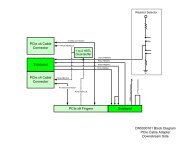
To connect to other systems, or off-board I/O, there are three "daughtercard" connectors provided. In<br />
the block diagram these appear as yellow rectangles unless you are colorblind then they are grey.<br />
DNV6F6PCIE User <strong>Manual</strong> Page 15
The user is expected to buy a daughter card that contains the I/O interface that is required, or to<br />
design their own.<br />
Four DDR3 sockets (red rectangles) are on the board to provide bulk memory for use in the FPGA.<br />
You can use standard, off-the-shelf laptop memory (SODIMM), or you can use one of the many<br />
memory technology DIMMs that the Dini Group provides.<br />
Getting data on and off the board is accomplished through the Marvell CPU. It provides USB,<br />
Ethernet, PCI Express, interfaces. It connected to the user FPGAs through the "NMB" interface,<br />
which is fast enough to sustain a full-speed x4 PCI Express connection to all FPGAs simultaneously.<br />
The interface inside the FPGA and on the host PC is very simple, because all of the software and<br />
hardware between has already been designed, proven, and optimized.<br />
3.2 Virtex 6 FPGA<br />
Virtex 6 is the most slightly better than Virtex 5 FPGA in the world. You will definitely want six of<br />
them.<br />
3.2.1 Stuffing Options<br />
Each of the six main FPGA locations can be installed with any compatible density of FPGA, or not<br />
installed at all, in any combination. In this way, you only will have to pay the (significant) FPGA<br />
cost for the FPGAs that you will actually use.<br />
Below there is a table that describes the major differences between the available FPGAs. Only<br />
FPGAs that Xilinx sells in the "FF1159" package are compatible with this board.<br />
FPGA Speed<br />
Grades<br />
Flip-flops Equivalent<br />
ASIC Gates<br />
All Board<br />
Features?<br />
25x18<br />
multipliers<br />
Memory<br />
(bits)<br />
LX550T 1L, 1, 2 687,360 4.0M Y 864 22.8M<br />
LX360T 1L, 1, 2, 3 455,040 2.6M N 576 15.0M<br />
LX240T 1L, 1, 2, 3 301,440 1.7M N 768 15.0M<br />
SX475T 1L, 1l, 2 595,200 3.4M Y 2016 38.3M<br />
SX315T 1L, 1, 2, 3 394,000 2.3M N 1344 25.3M<br />
Each LX550T FPGA can emulate approximately 4 million ASIC gates reasonably, however I just<br />
made this number up. It is strongly recommended that you synthesize your actual ASIC design,<br />
mapping to FPGA technology to get an accurate FPGA utilization estimate.<br />
3.2.2 Speed Grades<br />
Xilinx FPGAs usually come in three speed grades. There is no rule of thumb to estimate which speed<br />
grade you will need to run your design at your target frequency. You will only know this once you<br />
have run a synthesis, with FPGA place-and-route, targeting the actual FPGA device skew that you<br />
will be using.<br />
DNV6F6PCIE User <strong>Manual</strong> Page 16
3.2.3 Upgrades<br />
If you would like to install only some FPGAs when you order the board, and later add FPGAs or<br />
upgrade FPGAs to larger parts, this is possible; however you should request this before ordering the<br />
board.<br />
3.2.4 Small FPGAs<br />
When one or more of the FPGA locations is populated with a LX360T, LX240T, or SX315T, the<br />
some features of the board become unavailable. This is because these three FPGAs have fewer I/O<br />
than physically exist on the 1759-pin BGA package. The on-board devices that the unused physical<br />
package pins are connected to cannot be used if the populated FPGA is one of these "small" FPGAs.<br />
On the product block diagram, signals that may be unusable due to "small" FPGAs are colored<br />
orange. Below there is a copy of the block diagram, with all orange signals removed. The block<br />
diagram below represents the features available on a board, even if "small" FPGAs are selected.<br />
3.2.5 Safe Handling of FPGAs<br />
There are three easy ways to break the FPGAs.<br />
1) Static electricity<br />
Make sure you keep the board on a static controlled surface, and that you neutralize your body with<br />
that surface before handling the board. Especially sensitive are the FPGA I/Os. These are exposed on<br />
the daughter card headers and also everywhere else.<br />
2) High Voltage<br />
The FPGA I/O can only withstand voltages below and up to the VCCO power supply. When<br />
interfacing the board to some external I/O, make sure your I/O signals are driven at levels that do not<br />
exceed VCCO. If you do not know what VCCO is, then you probably should not be interfacing the<br />
DNV6F6PCIE User <strong>Manual</strong> Page 17
oard to some external I/O. Note that the maximum allowable VCCO on Virtex 6 is 2.5V. If you are<br />
interfacing with a 3.3V device, then you automatically lose.<br />
3) Board warp<br />
If the board undergoes mechanical stress, the FPGA pins (balls) can separate from the PCB and<br />
result in non-connected signals. The only way I have seen people doing this is by installing and<br />
removing connectors. Make sure that when installing a connector, you are supporting the connector<br />
from the opposite side, so that board warp does not absorb the force of the insertion.<br />
3.3 Clock Resources<br />
The board provides clocks. Clocks are one of the features that board provides. There are clocks on<br />
the board. You can use the clocks that are on the DNV6F6 for clocking.<br />
3.3.1 Clock pins on the FPGA<br />
The Virtex 6 has many fewer "global clock" (GC) pins that previous generations. Instead there are<br />
"Clock Capable" (CC) pins that have restrictions on how they are used. Only some of the "global<br />
clock" networks on the DNV6F6 are connected to "GC" pins on the FPGA. The rest are connected<br />
on "clock capable" pins. A "clock capable" pin might be a MRCC ("multiple region clock capable")<br />
or SRCC ("single-region clock capable"). You will have to consult a datasheet to tell the difference.<br />
The use of each type of pin, MRCC, SRCC, GC result in different effects on timing.<br />
Also, banks 10-18 have different timing than banks 20-38. All "global clock" pins on the DNV6F6<br />
are connected to banks 20-38.<br />
It would be difficult and misleading if I tried to explain how clocks worked internally in a Virtex 6,<br />
so you will need to consult the data book. We tried to connect them to make them as useful and<br />
flexible as possible.<br />
3.3.2 Global Networks<br />
The "global clocks" are the clocks that are provided to all 6 FPGAs, with low skew between the<br />
arrival of the clock pulses at each FPGA. There are 6 such networks. USER_R, USER_L, G0, G1,<br />
G2, and CLK_25<br />
DNV6F6PCIE User <strong>Manual</strong> Page 18
Each of them is suitable for synchronous communication between FPGAs.<br />
3.3.3 Clocks G0, G1, G2<br />
The clocks G0, G1 and G2 are from a synthesizer that can produce any frequency from 2KHz to<br />
700MHz with a 50ppm tolerance or better.<br />
DNV6F6PCIE User <strong>Manual</strong> Page 19
The synthesizer used is a high-performance, low jitter, high-precision clock generator chip, the<br />
Si5326. To change the clock frequency you can use the EMU software.<br />
The clocks G0, G1 and G2 can also be set to come from the config FPGA. The config FPGA in turn,<br />
can be set to source this clock from the FPGAs. In this way, FPGAs can drive the frequency onto the<br />
global clock networks. This can be useful for controlled clocks and step-clocks. It can also be useful<br />
when a local clock for an FPGA needs to be delivered to all 6 FPGAs with zero delay.<br />
G0 can be sourced from FPGA A or FPGA D. The signal that the FPGA should drive when this<br />
mode is used is called CLK_TO_SPARTAN_Ap and CLK_TO_SPARTAN_Dp respectively.<br />
G1 can be sources from FPGA B or FPGA E. The signal that the FPGA should drive when this mode<br />
is used is called CLK_TO_SPARTAN_Bp and CLK_TO_SPARTAN_Ep respectively.<br />
G2 can be sourced from FPGA C or FPGA F. The signal that the FPGA should drive when this mode<br />
is used is called CLK_TO_SPARTAN_Cp and CLK_TO_SPARTAN_Fp respectively.<br />
3.3.4 CLK_25<br />
This clock network is fixed at 25Mhz. You cannot change it, try as you might.<br />
68 CLK_25_SOURCEp<br />
68 CLK_25_SOURCEn<br />
From Spartan<br />
+3.3V<br />
C394<br />
0.1uF<br />
R1018<br />
4.7K<br />
C386<br />
0.1uF<br />
R995<br />
100R<br />
BUF_24_OE<br />
C385<br />
0.1uF<br />
Fixed<br />
Frequency<br />
16<br />
15<br />
22<br />
18<br />
21<br />
U35<br />
CLK<br />
nCLK<br />
OE<br />
17<br />
19<br />
VDD<br />
20<br />
VDD<br />
VDD<br />
GND<br />
GND<br />
14<br />
Q0<br />
13<br />
nQ0<br />
12<br />
Q1<br />
11<br />
nQ1<br />
10<br />
Q2<br />
9<br />
nQ2<br />
8<br />
Q3<br />
7<br />
nQ3<br />
6<br />
Q4<br />
5<br />
nQ4<br />
4<br />
Q5<br />
3<br />
nQ5<br />
2<br />
Q6<br />
1<br />
nQ6<br />
24<br />
Q7<br />
23<br />
nQ7<br />
ICS85408<br />
SOP65P640X120-24N<br />
CLK_25_TPp<br />
CLK_25_TPn<br />
TP57<br />
DNI<br />
R994<br />
100R<br />
CLK_25_Ap 60<br />
CLK_25_An 60<br />
CLK_25_Bp 60<br />
CLK_25_Bn 60<br />
CLK_25_Cp 60<br />
CLK_25_Cn 60<br />
CLK_25_Dp 60<br />
CLK_25_Dn 60<br />
CLK_25_Ep 60<br />
CLK_25_En 60<br />
CLK_25_Fp 60<br />
CLK_25_Fn 60<br />
CLK_25_CONFIGp 68<br />
CLK_25_CONFIGn 68<br />
LVDS<br />
To<br />
all<br />
FPGAs<br />
3.3.5 USER_L<br />
This clock has no frequency synthesizer, but can come from a variety of sources.<br />
TP15<br />
LVDS<br />
DNI<br />
LVDS<br />
U26<br />
U25<br />
2<br />
16<br />
CLK_USER_LEFTp<br />
R564 16<br />
14 CLK_USER_LEFT_TPp<br />
42 CLK_USER_LEFT_OUTAp<br />
3<br />
CLK0p Q0p<br />
15<br />
CLK_USER_LEFTn<br />
100R 15<br />
CLK Q0<br />
13 CLK_USER_LEFT_TPn<br />
4<br />
VT0<br />
Q0n<br />
nCLK nQ0<br />
12<br />
42 CLK_USER_LEFT_OUTAn<br />
CLK0n<br />
Q1<br />
CLK_USER_LEFT_Ap 9<br />
LVDS<br />
11<br />
nQ1<br />
CLK_USER_LEFT_An 9<br />
7<br />
LVDS<br />
+3.3V<br />
10<br />
60 CLK_USER_LEFT_OUTDp<br />
CLK_USER_LEFT_Bp 44<br />
8<br />
CLK1p<br />
Q2<br />
9<br />
nQ2<br />
CLK_USER_LEFT_Bn 44<br />
9<br />
VT1<br />
R548<br />
8<br />
60 CLK_USER_LEFT_OUTDn<br />
CLK1n<br />
Q3<br />
CLK_USER_LEFT_Cp 45<br />
4.7K<br />
7<br />
BUF_USER_LEFT_OE 22<br />
nQ3<br />
CLK_USER_LEFT_Cn 45<br />
14<br />
6<br />
44 CLK_USER_LEFT_OUTBp<br />
OE Q4<br />
CLK_USER_LEFT_Dp 42<br />
13<br />
CLK2p<br />
5<br />
+2.5V<br />
17<br />
nQ4<br />
CLK_USER_LEFT_Dn 42<br />
12<br />
VT2<br />
4<br />
44 CLK_USER_LEFT_OUTBn<br />
CLK2n<br />
19<br />
VDD Q5<br />
CLK_USER_LEFT_Ep 47<br />
3<br />
20<br />
VDD nQ5<br />
CLK_USER_LEFT_En 47<br />
19<br />
2<br />
3 CLK_USER_LEFT_SPARTANp<br />
VDD Q6<br />
CLK_USER_LEFT_Fp 45<br />
18<br />
CLK3p<br />
1<br />
CLK_USER_LEFT_Fn 45<br />
17<br />
VT3<br />
18<br />
nQ6<br />
24<br />
3 CLK_USER_LEFT_SPARTANn<br />
CLK3n<br />
CLK_USER_LEFT_Qp 68<br />
21<br />
GND Q7<br />
23<br />
6<br />
GND nQ7<br />
CLK_USER_LEFT_Qn 68<br />
3 CLK_USER_LEFT_MUX_SEL0<br />
5<br />
SEL0<br />
C127 C139 C128<br />
3 CLK_USER_LEFT_MUX_SEL1<br />
SEL1<br />
0.1uF 0.1uF 0.1uF<br />
ICS85408<br />
10<br />
1<br />
SOP65P640X120-24N<br />
11<br />
GND<br />
VDD<br />
20<br />
GND<br />
VDD<br />
C145<br />
ICS854057/TSSOP20<br />
0.1uF<br />
R570<br />
100R<br />
To<br />
all<br />
FPGAs<br />
DNV6F6PCIE User <strong>Manual</strong> Page 20
The following list are the available sources for the clock USER_L<br />
FPGA A SRC The FPGA A should drive the signal<br />
CLK_USER_LEFT_OUTAp/n differentially<br />
FPGA B SRC The FPGA B should drive the signal<br />
CLK_USER_LEFT_OUTBp/n differentially<br />
FPGA D SRC The FPGA D should drive the signal<br />
CLK_USER_LEFT_OUTDp/n differentially<br />
SMA The user should supply a clock single-ended into the SMA P36,<br />
located on the bottom right of the board. Voltages up to +2.5V<br />
are acceptable.<br />
MGT<br />
The clock will be the same frequency as the "MGT" clock. This<br />
has a dubious and unknown use.<br />
3.3.6 USER_R<br />
These come from a USER FPGA. They are used for generating a frequency from an FPGA and then<br />
using that new frequency across the board. This is just like USER_L, except there are different<br />
choices for the inputs.<br />
CONN_SMA<br />
LIGHTHORSE_SASF546-P26-X1<br />
J5<br />
3 4<br />
1<br />
2 5<br />
CONN_SMA<br />
LIGHTHORSE_SASF546-P26-X1<br />
J6<br />
3 4<br />
1<br />
2 5<br />
+2.5V<br />
C702<br />
R456<br />
4.7K<br />
R494<br />
4.7K<br />
1uF<br />
3<br />
3<br />
60<br />
60<br />
60<br />
60<br />
45<br />
45<br />
LVDS<br />
CLK_USER_RIGHT_OUTCp<br />
CLK_USER_RIGHT_OUTCn<br />
CLK_USER_RIGHT_OUTEp<br />
CLK_USER_RIGHT_OUTEn<br />
CLK_USER_RIGHT_OUTFp<br />
CLK_USER_RIGHT_OUTFn<br />
CLK_SMA_USER_LEFTp<br />
CLK_SMA_USER_LEFTmid<br />
CLK_SMA_USER_LEFTn<br />
CLK_USER_RIGHT_MUX_SEL0<br />
CLK_USER_RIGHT_MUX_SEL1<br />
Clock MUXes<br />
2<br />
3<br />
4<br />
7<br />
8<br />
9<br />
14<br />
13<br />
12<br />
19<br />
18<br />
17<br />
6<br />
5<br />
10<br />
11<br />
U23<br />
CLK0p<br />
VT0<br />
CLK0n<br />
CLK1p<br />
VT1<br />
CLK1n<br />
CLK2p<br />
VT2<br />
CLK2n<br />
CLK3p<br />
VT3<br />
CLK3n<br />
SEL0<br />
SEL1<br />
GND<br />
GND<br />
Q0p<br />
Q0n<br />
LVDS<br />
VDD<br />
VDD<br />
ICS854057/TSSOP20<br />
16<br />
15<br />
1<br />
20<br />
LVDS<br />
+2.5V<br />
CLK_USER_RIGHTp<br />
CLK_USER_RIGHTn<br />
C91<br />
0.1uF<br />
+3.3V<br />
C105<br />
0.1uF<br />
R533<br />
4.7K<br />
C99<br />
0.1uF<br />
BUF_USER_RIGHT_OE<br />
C103<br />
0.1uF<br />
R523<br />
100R<br />
16<br />
15<br />
22<br />
17<br />
19<br />
20<br />
18<br />
21<br />
U24<br />
CLK<br />
nCLK<br />
OE<br />
VDD<br />
VDD<br />
VDD<br />
GND<br />
GND<br />
Q0<br />
nQ0<br />
Q1<br />
nQ1<br />
Q2<br />
nQ2<br />
Q3<br />
nQ3<br />
Q4<br />
nQ4<br />
Q5<br />
nQ5<br />
Q6<br />
nQ6<br />
Q7<br />
nQ7<br />
14<br />
13<br />
12<br />
11<br />
10<br />
9<br />
8<br />
7<br />
6<br />
5<br />
4<br />
3<br />
2<br />
1<br />
24<br />
23<br />
ICS85408<br />
SOP65P640X120-24N<br />
LVDS<br />
TP12<br />
DNI<br />
CLK_USER_RIGHT_TPp<br />
CLK_USER_RIGHT_TPn<br />
CLK_USER_RIGHT_Ap 9<br />
CLK_USER_RIGHT_An 9<br />
CLK_USER_RIGHT_Bp 44<br />
CLK_USER_RIGHT_Bn 44<br />
CLK_USER_RIGHT_Cp 45<br />
CLK_USER_RIGHT_Cn 45<br />
CLK_USER_RIGHT_Dp 42<br />
CLK_USER_RIGHT_Dn 42<br />
CLK_USER_RIGHT_Ep 47<br />
CLK_USER_RIGHT_En 47<br />
CLK_USER_RIGHT_Fp 45<br />
CLK_USER_RIGHT_Fn 45<br />
CLK_USER_RIGHT_Qp 68<br />
CLK_USER_RIGHT_Qn 68<br />
R511<br />
100R<br />
To<br />
all<br />
FPGAs<br />
FPGA C SRC<br />
FPGA E SRC<br />
FPGA F SRC<br />
SMA<br />
The FPGA C should drive the signal CLK_USER_LEFT_OUTCp/n<br />
differentially<br />
The FPGA E should drive the signal CLK_USER_LEFT_OUTEp/n<br />
differentially<br />
The FPGA F should drive the signal CLK_USER_LEFT_OUTFp/n<br />
differentially<br />
The user should supply a clock single-ended or differential into the<br />
SMAs J5 and/or J6, located near the top left corner of the board.<br />
Voltage levels up to +2.5V are acceptable.<br />
DNV6F6PCIE User <strong>Manual</strong> Page 21
3.3.7 Frequency-only networks<br />
Frequency only networks are networks that are provided to all six FPGAs, but do not guarantee lowskew<br />
between the inputs to the FPGAs. These networks should not be used for fully-synchronous<br />
communication between FPGAs, at least not without phase-adjustment.<br />
3.3.7.1 MGT<br />
The MGT clock network delivers a very low-jitter, high-precision frequency source to the MGT<br />
(GTP, GTX, HTX) tiles of all six FPGAs. This clock is intended to be used only for the RocketIO<br />
interconnect between FPGAs, however the clock is accessible for other types of logic inside the<br />
FPGA.<br />
The MGT network can be driven at one of four different frequencies. You can select the desired<br />
frequency from EMU. Additionally, you can run the MGT network at the same frequency as global<br />
clock G0. This will allow you to select any frequency that exists in the world.<br />
3.3.7.2 CCLK<br />
The "CCLK" pin on the FPGA, or the configuration clock, is used by the config FPGA to send<br />
configuration bitstreams to the FPGA over the selectmap bus. It is not a free-running clock, but has a<br />
minimum period of 20ns. It can be used in the FPGA in conjunction with the STARTUP_V6<br />
primitive. This clock is not configurable.<br />
DNV6F6PCIE User <strong>Manual</strong> Page 22
3.3.8 Local Networks<br />
Local networks are networks that are only delivered to a single FPGA.<br />
3.3.9 CLK_TO_*<br />
Some FPGAs have signals that connect from on FPGA to another FPGA's global clock input pin.<br />
These signals are single ended and are called "clk_to_*" where * is either A, B, C, D, E or F. These<br />
can be used for forward a clock from one FPGA to another, without having to use "local routing"<br />
within the FPGA. The utility of this does not exceed 3 utils.<br />
3.3.10 Spartan/TP<br />
There is a test point connected to at least on clock input of each FPGA. There is no known use.<br />
3.3.11 Daughtercard Feedback<br />
Each FPGA that has a daughter card connector also has a signal that loops back from an FPGA<br />
output to a clock input of that same FPGA. The routing length of this signal is the same as the<br />
routing length of the I/O signals to the daughter card. The purpose of this is so that it is possible to<br />
have a clock in the FPGA that is phase-aligned to a clock arriving at the daughter card. The signal is<br />
called "DC*_FEEDBACK_P/N"<br />
3.3.12 DIMM Feedback<br />
Similarly, each FPGA that has a DIMM interface has a signal that is looped back from an output of<br />
the FPGA to a clock input of the FPGA. The routing length of this feedback is equal to the routing<br />
length of the signals to the DIMM connector. In this way, it is possible to have a clock inside the<br />
FPGA that is phase aligned with the arrival of the clock at the DIMM. The signal is called<br />
"DIMM*_FB_P/N"<br />
DNV6F6PCIE User <strong>Manual</strong> Page 23
3.3.13 From SEAM connector<br />
The SEAM daughter card provides four clock inputs delivered to the MGT (GTP, GTX, HTX) tiles<br />
of the connected FPGA. This clock is intended to be used for RocketIO communication with the<br />
SEAM interface, however it can be used in the FPGA for other types of logic.<br />
3.3.14 NMB<br />
The NMB interface includes one clock signal running at xxxxxx MHz. This clock is free-running,<br />
and is not configurable. It is received by each FPGA at the same frequency, however the phase<br />
relationship between the arrival of the clock at each FPGA is indeterminate.<br />
3.3.15 Generating clocks from FPGAs<br />
Notice how earlier I said that some of the clock networks can be driven from FPGAs? Well that<br />
means you can do all of your frequency generation in an FPGA.<br />
3.3.16 Clocking features not implemented<br />
Four of the networks can be driven from the configuration FPGA. If you need some special feature,<br />
then we could potentially add it. For example, single-step clocks, clocks from FPGA-to-FPGA.<br />
3.4 NMB Bus<br />
The NMB bus is the primary means you will use to get high quantities of data on and off the board.<br />
If you want to use the provided software (EMU) to push data to the board over USB, Ethernet and<br />
PCI Express, then you are required to interface to NMB in your FPGA design.<br />
3.4.1 Protocol<br />
You are expected to know nothing about the protocol of NMB and only interface to it using the<br />
provided HDL interface wrapper in your FPGA on one end, and in the EMU C++ code on the other<br />
end. However, the marketing material constantly makes reference to the inner workings of the<br />
underlying hardware and software, so I feel obligated to sort of describe it a little. This short section<br />
describes the implementation of the interface. I recommend you skip this "protocol" section. It is<br />
useless to know anything here.<br />
DNV6F6PCIE User <strong>Manual</strong> Page 24
There is a block diagram of the NMB bus architecture above. It is physically point-to-point from<br />
each FPGA to the configuration FPGA. Each point-to-point connection consists of a 40-pin signal<br />
wire, which are used as 20 LVDS pairs. These pairs are further divided into 10 signals in each<br />
direction, with 1 clock signals, 1 control signal and 8 data signals. The clock frequency of the<br />
interface happens to be 1GHz (500 MHz clock with DDR capture). The theoretical throughput is<br />
therefore 1GB/sec in both directions simultaneously, to all 6 FPGAs simultaneously.<br />
The protocol supports four channels, demand mode, bursts, interrupts, link detection, some FIFO<br />
flags, and maybe some other stuff. The data to/from the FPGA is stored in buffers in the DRAM of<br />
the Marvell processor.<br />
3.4.2 User Interface<br />
An HDL module is provided in the support package around here:<br />
D:/FPGA_Rererence_designs/code/common/nmb/nmb_target_interface.v<br />
There is hopefully a PDF in that directory that gives a much better description of how to actually use<br />
the interface. But more or less the interface provides a simple Address/DataIn/DataOut type<br />
interface. You should think of the interface as a memory space.<br />
On the C++ side of the NMB there are simple functions like<br />
nmb_read(address, buffer, size)<br />
that can be used to view this memory space. The code for this is found in the support package here<br />
D:/Host_software_applications/Emu/EmuLib/dnapi.h<br />
DNV6F6PCIE User <strong>Manual</strong> Page 25
Hopefully there is also a PDF there that describes how to use it.<br />
3.4.3 Memory Spaces<br />
You should probably read the PDF describing dnapi.h instead of this document.<br />
D:\Host_Software\emu\Documents\Emu_<strong>Manual</strong>.pdf<br />
But here it goes: The memory space is 64-bit. Each address represents a single byte, however the<br />
data is required to be read and written in blocks of 32-bit. Addresses supplied to the interface must<br />
be divisible by 4. Therefore, the bottom 2 bits of the address space are stupid.<br />
Additionally, since there are no chip-selects on the NMB bus, it is necessary to pre-allocate address<br />
ranges for devices on the bus. On this board, there are six devices, and the NMB address ranges that<br />
they are able to respond to on the bus are given here:<br />
Target Starting Address End Address<br />
FPGA A 0x00000000_00000000 0x00FFFFFF_FFFFFFFF<br />
FPGA B 0x01000000_00000000 0x01FFFFFF_FFFFFFFF<br />
FPGA C 0x02000000_00000000 0x02FFFFFF_FFFFFFFF<br />
FPGA D 0x03000000_00000000 0x03FFFFFF_FFFFFFFF<br />
FPGA E 0x04000000_00000000 0x04FFFFFF_FFFFFFFF<br />
FPGA F 0x05000000_00000000 0x05FFFFFF_FFFFFFFF<br />
3.4.4 Error Conditions<br />
Exist.<br />
3.5 FPGA Interconnect<br />
Most of the I/O on the FPGA are used to connect each FPGA to other FPGAs. Most interconnect is<br />
routed point-to-point between FPGAs, in a nearest neighbor topology. The exact topology is shown<br />
in the diagram below.<br />
DNV6F6PCIE User <strong>Manual</strong> Page 26
Note that the interconnect that is drawn in a gold color in the diagram is only available when both<br />
connected FPGAs are either the LX550T device, or the SX475T device. If either FPGA is a "small"<br />
FPGA device, then the signals are not usable. This is because the "small" FPGA devices do not allow<br />
the use of all of the pins of the FPGA as I/O.<br />
3.5.1 I/O protocol<br />
The protocol for the use of the I/O is user defined. The VCCO pin of the FPGA on each bank that is<br />
used for interconnect is +2.5V. This means that LVCMOS25 and LVDS are both reasonable choices<br />
for the IOSTANDARD attribute.<br />
The board features necessary to use terminated standards, such as LVDCI or SSTL are not provided<br />
on the board, and so DCI cannot be used for FPGA-to-FPGA communication. When using LVDS,<br />
you can still use the DIFF_TERM attribute to terminate signals.<br />
Since the "global clocks" on the board are delivered to each FPGA with low skew, any of the<br />
"global clocks" are suitable for use for FPGA interconnect.<br />
3.5.2 High-Speed interconnect<br />
The interconnect between FPGAs are divided into "banks". A single bank on one FPGA always<br />
connected to a single bank on one other FPGA. This pairing up of banks allows the use of some of<br />
the high-speed features of the Virtex 6, such as BUFR clocking, and ISERDES and OSERDES.<br />
Every "bank" of interconnect contains at least one LVDS pair in each direction that goes to a "clock<br />
capable" pin on the FPGA. This pair can be used as a clock to input all of the bits on that bank. The<br />
net name of this pair ends in "_CC" in the schematic.<br />
DNV6F6PCIE User <strong>Manual</strong> Page 27
To achieve the highest switching rates on the interconnect banks, you must use the LVDS<br />
IOSTANARD.<br />
3.5.3 Signal net length report<br />
The shortest FPGA-to-FPGA interconnect signals is 40mm long. The longest is 290mm long. This<br />
corresponds to a skew of about 2ns.<br />
Within any single bus, the greatest skew is 75mm. This corresponds to 0.5 ns of skew.<br />
3.6 SODIMM (DDR3) Connectors<br />
For memory expansion, the DNV6F6PCIe has four socket connectors connected to four of the user<br />
FPGAs. The sockets accept standard off-the-shelf DDR3 laptop memory. The interface and reference<br />
design is compatible with any density or organization of memory.<br />
These sockets can also be used for types of memory other than DDR3 DRAM. Dini Group has a<br />
variety of modules that are compatible with the DNV6F6PCIe, including synchronous SRAM and<br />
others.<br />
The SODIMM interface is also potentially usable as an expansion interface for custom daughter<br />
cards.<br />
DNV6F6PCIE User <strong>Manual</strong> Page 28
3.6.1 Memory Interface Generator<br />
The provided reference design uses a memory controller that is based on the memory controller that<br />
is produced by the "Memory Interface Generator" (MIG), part of the ISE software. However it has<br />
been modified. The modifications allow the use of dual-rank DIMMs, and also set some parameters<br />
automatically, such are RAS and CAS latencies, and total DIMM density.<br />
Some of the signals that are connected between the SODIMM connector and the FPGA are not used<br />
by MIG. These include the SODIMM "NC" (no connect) pins, the upper two address pins, the<br />
EVENTn pin.<br />
Additionally, the "feedback" clock is not used by MIG, or the DDR3 controller provided by Dini<br />
Group.<br />
If you want to use MIG you should use the HDL files produced by MIG, and use the UCF file<br />
provided by Dini Group, removing the unused signals.<br />
3.6.2 IO Standards<br />
The DIMM interface is voltage-selectable. When using DDR3 memory, it is suggested to use the<br />
1.5V IO voltage. When using this voltage, signals to the SODIMM should be of the IO Standard<br />
SSTL_II_18_DCI or SSTL_II_18_DIFF_DCI. The necessary board features to make SSTL work<br />
properly are provided.<br />
DNV6F6PCIE User <strong>Manual</strong> Page 29
The EVENTn pin is also voltage selectable. It will be the same voltage as the rest of the DIMM.<br />
There are some LED signals on the FPGA that are connected to the DIMM bank. The<br />
IOSTANDARD attribute of these signals must be changes to match the voltage of the DIMM.<br />
The IIC signals (SDA and SCL) are fixed at +2.5V and should use a 2.5V standard.<br />
3.6.3 Voltage Selection<br />
Off-the-shelf DDR3 DRAM always uses 1.5V core power and IO signaling levels. If you are using<br />
DRAM, then you would never need to change the voltage output of the DRAM interfaces. However,<br />
when using alternate memory modules from Dini Group, or when designing your own daughter<br />
cards, you may need to supply a different voltage to the SODIMM and to the attached pins of the<br />
FPGA.<br />
+5.0V<br />
This<br />
resistor is<br />
duplicated<br />
on other<br />
pages<br />
R1193<br />
1K<br />
5,6,7,59 SEQ_DISABLE_VCCO#<br />
Silkscreen:<br />
R1192 1K<br />
1.35V<br />
1.5V<br />
1.8V<br />
Install all for 2.5V<br />
R1180<br />
DNI<br />
U91-1<br />
J32<br />
REG_DIMMA_TRACK E1<br />
G2 REG_DIMMA_FB<br />
1 2 REG_DIMMA_FB135 R1371 30K<br />
TRACK FB<br />
3 4 REG_DIMMA_FB15 R1370 13.7K<br />
REG_DIMMA_RUN D1<br />
5 6 REG_DIMMA_FB18 R1369 6.8K<br />
R1191 0R<br />
RUN/SS<br />
R1146 7 8 REG_DIMMA_FB25 R1368 19.1K<br />
REG_DIMMA_COMP G1<br />
DNI<br />
COMP<br />
B3 REG_DIMMA_SW0<br />
R1171<br />
F1 O.D.<br />
SW<br />
B4 REG_DIMMA_SW1<br />
TSM-136-01-T-DV<br />
DNI<br />
PGOOD SW<br />
LTM4604A/LGA66<br />
R1136<br />
DNI<br />
1.2V - 10K 1.35V - 7.25K<br />
2.7V - 2.1K 1.5V - 5.76K<br />
R1161<br />
1.8V - 4.02K<br />
10K_0.1%<br />
59 PWR_FAULTn_DIMMA<br />
2.5V - 2.37K<br />
Each SODIMM interface has an isolated regulator that allows you to independently select the<br />
voltage. There is a header next to each SODIMM where you can install jumpers to affect the output<br />
voltage of this regulator. To change the voltage, remove all jumpers currently installed on the header,<br />
and install a jumper next to the silkscreen text showing that voltage that you want. Be sure to probe<br />
the DIMM_VDD test point once you have completed the change.<br />
DNV6F6PCIE User <strong>Manual</strong> Page 30
3.6.4 Daughter cards<br />
If you want to make your own custom daughter card for use in the SODIMM sockets, you are<br />
encouraged to download the complete schematic and layout files for one of our existing custom<br />
modules. These are available on our website with no restrictions on use.<br />
The signals on the DNV6F6PCIE circuit board are routes as 50-ohm impedance. Every signal<br />
connecting to the DIMM is length-matched, including the feedback clock.<br />
Check this webpage to see existing DIMMs and to access the schematic and layout files for existing<br />
DIMMs.<br />
http://dinigroup.com/index.php?page=DNSODM204<br />
3.6.5 Net Length Report<br />
The length of all signals from the FPGA to the SODIMM are length and delay-matched.<br />
3.7 Daughter Card Connectors<br />
The primary means of interfacing to the FPGA with external IO are through the 400-pin MEG-Array<br />
expansion connectors. There are three of these high-speed, high-density connectors on the board,<br />
DNV6F6PCIE User <strong>Manual</strong> Page 31
connected to FPGAs D,E and F. The FPGA connection to each of the three connectors is the same.<br />
The physical layout requirements of each of the three connectors is the same.<br />
They are located on the back side of the board in order to leave plenty of flexibility for the<br />
mechanical layout of the board.<br />
DNV6F6PCIE User <strong>Manual</strong> Page 32
3.7.1 Electrical Spec<br />
60 DCD_CLK_DN_IN_P<br />
60 DCD_CLK_DN_IN_N<br />
42 DCD_CLK_UP_OUT_P<br />
42 DCD_CLK_UP_OUT_N<br />
E1<br />
F1<br />
E3<br />
F3<br />
P12-1<br />
CLK_DN_2.5_P<br />
CLK_DN_2.5_N<br />
CLK_UP_2.5_P<br />
CLK_UP_2.5_N<br />
PLUG<br />
+12V<br />
+12V<br />
RSVD_PWR<br />
RSVD_PWR<br />
+3.3V<br />
+3.3V<br />
+2.5V_LDO<br />
A1<br />
K1<br />
C1<br />
H1<br />
B2<br />
D2<br />
G2<br />
DCDVFUSED<br />
DCDSVD R5 DNI<br />
RESC1005N<br />
DCD3VFUSED<br />
DAUGHTERCARD_RESET_POWER 36,39<br />
F3<br />
5A<br />
FUSE_0429<br />
F6<br />
5A<br />
FUSE_0429<br />
+12V_R<br />
+3.3V<br />
DCDCO_CAP<br />
C59<br />
1uF<br />
K20<br />
VCCO_CAP<br />
RSTn_3.3_TOLERANT<br />
PLUG<br />
J2<br />
DAUGHTERCARD_RESETn 36,39<br />
MEG_400_Plug_Stratix3_30<br />
3.7.2 IO Electrical<br />
The part number of the connector part installed on the DNV6F6 is "84520102LF" from FCI. It is<br />
intended that the part number that will be used to connector to this board is the FCI 74390-101 part.<br />
The part 84520102LF is called the "plug" and the 74390-101 is called the "receptacle"<br />
The DNV6F6 is the "host" side of the interface. The mating card is called the "daughtercard"<br />
All signals from the FPGA to the connector are length matched to each other with a minimum<br />
tolerance of 50ps on all Dini Group host boards. All Dini host boards route the FPGA I/O signals as<br />
50-ohm transmission lines.<br />
It is recommended that daughter cards provide a bypass capacitor between the pins B0_VCC0,<br />
B1_VCC0, B2_VCC0, B3_VCC0, B4_VCC0 and ground close to the connector pin on the daughter<br />
card.<br />
Note that Virtex 6 is incompatible with +3.3V I/O signaling completely. +2.5V is the maximum<br />
supported I/O voltage. If you require +3.3V I/O, you must use voltage translation devices.<br />
3.7.2.1 _V pins<br />
Any pin name that ends in the string "_V" is a "VREF" pin.<br />
DNV6F6PCIE User <strong>Manual</strong> Page 33
For some settings of the FPGA I/O attribute IOSTANDARD, you are required to supply a 1/2 VCCO<br />
voltage onto the "VREF" pins of the FPGA. If a daughtercard requires one of these IOSTANDARD<br />
settings, it must generate the VREF voltage, and drive it back on the _V pins of the daughtercard.<br />
There are no-stuff capacitor locations on the host board attached to all "VREF" pins that can be<br />
populated with capacitors, if this is required by your electrical analysis. Note that installing these<br />
capacitors will negatively impact the switching speed of these signals when used as regular I/O.<br />
3.7.2.2 _CC pins<br />
Any pin whose name ends in "_CC" is a "CC" pin.<br />
CC pins and _MRCC pins are connected to "CC" pins or "MRCC" pins on the host board's FPGA.<br />
You should see the Virtex 6 SelectIO user guide for the implications of this. But in general, these<br />
pins are suitable for I/O clocks driven from the daughtercard to the host FPGA.<br />
The "CC" pins are able clock I/O in other FPGA banks in some cases. For this capability, there are<br />
requirements that the banks have certain physical relationships to each other on the silicon die of the<br />
FPGA device. During the assignment of FPGA banks to the daughtercard, no provisions were made<br />
to restrict the bank selection to make cross-bank clocking consistent from one daughtercard header to<br />
the next. It is recommended that is CC pins are required, that a separate copy of the clock is driven to<br />
each FPGA bank that requires it, and do not rely on "multi-clock" regions.<br />
3.7.2.3 VRP and VRN Pins<br />
On all FPGA banks that are connected to the daughtercard, VRP and VRN pins are correctly<br />
connected to allow DCI to be used with the daughtercard. Note that there is still the Virtex 6 I/O rule<br />
that only a single type of DCI may be used per bank of the FPGA. This requirement may limit the<br />
use of DCI on the daughter card. The requirement is too complicated to describe here, so you may<br />
need to run a test place-and-route of your design to determine whether your desired pin out is<br />
acceptable.<br />
3.7.3 Reset Signal<br />
The signal RSTn_3.3V_TOLERANT is valid when +2.5V_LDO is above 0.7V. At all times, when<br />
the signal RSTn_3.3V_TOLERANT is valid, and has a voltage measuring below 0.7V, then all<br />
boards using this interface (host and daughtercard) must tri-state all I/O signals connected to the<br />
interface. Daughter cards that fail to tri-state signals until the de-assertion of<br />
RSTn_3.3V_TOLERANT may risk damaging the DNV6F6 board. The DNV6F6 will weakly pull up<br />
this signal to +2.5V. A daughter card is free to also pull up this signal weakly to any voltage between<br />
0.7V and 3.3V<br />
DNV6F6PCIE User <strong>Manual</strong> Page 34
+2.5V<br />
R4<br />
2.0K_0.1%<br />
R3<br />
1K<br />
+2.5V<br />
R6<br />
DNI<br />
R7<br />
1K<br />
R2<br />
MON_DC_ADJ1<br />
MON_DC_ADJ2<br />
DNI MON_DC_SEL<br />
U6<br />
1<br />
2<br />
ADJ1<br />
ADJ2<br />
3<br />
8<br />
REF<br />
SEL<br />
LTC2909<br />
VCC<br />
RST<br />
TMR<br />
GND<br />
6<br />
5<br />
7<br />
4<br />
MON_DC_TMR<br />
C2<br />
C4<br />
DNI<br />
TP2<br />
DNI<br />
TESTPOINT<br />
R347<br />
10K_0.1%<br />
DAUGHTERCARD_RESETn 36,39<br />
0.1uF<br />
+12V_R<br />
DC Linear Power Supply 2.5V @ 1mA<br />
R1<br />
1K<br />
RESC1005N<br />
Current<br />
Limits to<br />
20mA<br />
REG_DC_RESET_IN<br />
C614<br />
4.7uF_12V<br />
C6<br />
0.1uF<br />
U22<br />
8<br />
IN<br />
5<br />
LT1963AES8/SO8<br />
OUT<br />
SHDN SENSE/ADJ<br />
3<br />
6<br />
GND<br />
7<br />
GND<br />
GND<br />
NC<br />
1<br />
2<br />
4<br />
DAUGHTERCARD_RESET_POWERq<br />
REG_DC_RESET_ADJ<br />
R372<br />
6.04K<br />
R353<br />
6.8K<br />
C3<br />
4.7uF<br />
C5<br />
0.1uF<br />
D1<br />
1 2<br />
DIO_DFLS130L-7<br />
DAUGHTERCARD_RESET_POWER 36,39<br />
Requires a GND area fill for thermal<br />
performance, reference the<br />
datasheet.<br />
3.7.4 Power<br />
The DNV6F6 supplies power to the daughtercard at two voltages, 12V and 3.3V. Each pin of the<br />
Meg connector can supply no more than 1A of current, so the effective power limit of the<br />
daughtercard is 2A x 12V + 3A x 3.3V = 33.9W.<br />
It is strongly recommended that daughter cards provide a means of isolating (series resistor) their<br />
power net with the host board, and provide a means of bypassing the power input with an external<br />
power connector.<br />
On other Dini Group boards, the pins C1 and H1 may be power pins. On the DNV6F6, these pins are<br />
no-connects.<br />
The daughtercard should never be capable of supplying current back onto the host board on the<br />
+12V or +3.3V nets. This could potentially damage the host board.<br />
3.7.5 VCCO Power<br />
The FPGA I/O power pins are connected directly to the meg-array daughtercard interface. The<br />
intention of this design is for the daughtercard to drive the necessary I/O voltage back onto the host<br />
board. There are linear voltage regulators on the DNV6F6 that bias these power rails to 1.2V,<br />
however it is not recommended that you use these to power the daughtercard I/O. These regulators<br />
can supply up to 1A of current.<br />
If you build a daughter card that drives current back to the host board, it must be able to supply the<br />
current not only for the daughter card I/O, but also for the I/O current requirements of the host board.<br />
DNV6F6PCIE User <strong>Manual</strong> Page 35
If you forget to include voltage regulators for VCCO on the daughtercard, you can rework the<br />
DNV6F6 bias regulators to output your required voltage, so only as the combined current<br />
requirements of the FPGA banks and the daughtercard do not exceed 1A per bank. Note that the 5<br />
voltage regulators on the host board are not set up to evenly share current loads, and that each must<br />
be individually load limited to 1A.<br />
DCD_B0_VCCO<br />
DCD_B1_VCCO<br />
DCD_B2_VCCO<br />
DCD_B3_VCCO<br />
DCD_B4_VCCO<br />
1<br />
2<br />
3<br />
4<br />
5<br />
6<br />
P3<br />
1<br />
2<br />
3<br />
4<br />
5<br />
6<br />
DNI<br />
HDR6<br />
There is a row of test points next to each daughtercard header allowing the easy probing of the 5<br />
voltage rails on the daughtercard interface.<br />
R367<br />
DNI<br />
+2.5V<br />
C18<br />
4.7uF<br />
U17<br />
8<br />
IN<br />
5<br />
OUT<br />
SHDN SENSE/ADJ<br />
3<br />
6<br />
GND<br />
7<br />
GND<br />
GND<br />
NC<br />
LT1963AES8/SO8<br />
SOIC127P600X175-8N<br />
1<br />
2<br />
4<br />
REG_DCD_ADJ_B0<br />
R397<br />
0R<br />
R398<br />
4.7K<br />
Arrogantly<br />
assumes more<br />
capacitance is<br />
on bank<br />
DCD_B0_VCCO 31<br />
36,39 DAUGHTERCARD_RESETn<br />
This is the bias regulator. There is one for each of the 5 banks on each daughtercard interface.<br />
3.7.6 Clock Pins<br />
The clock pins E1, F1, E3, F3 are always connected to 2.5V I/O on the FPGA. They are connected to<br />
clock input pins near the center of the FPGA, making them suitable for sending a clock from the<br />
daughter card to the host FPGA. They are not externally terminated on the board, but you can use<br />
DIFF_TERM in the FPGA if you are using differential signaling.<br />
In addition to these two clocks, there is a variable-voltage clock input to the host FPGA. This signal,<br />
B0_P1?_GCC_TERM is located on bank 0. The input levels will be determined by the bank 0<br />
voltage, and the IOSTANDARD settings of the I/O in the FPGA. There exists external endtermination<br />
resistors on the host board, terminating to a voltage of VCCO/2. This termination<br />
scheme will result in a high current on the signal.<br />
DNV6F6PCIE User <strong>Manual</strong> Page 36
H42<br />
J39<br />
K36<br />
L33<br />
M30<br />
T28<br />
C846<br />
1uF<br />
U3-12<br />
VCCO_25<br />
VCCO_25<br />
VCCO_25<br />
VCCO_25<br />
VCCO_25<br />
VCCO_25<br />
FPGA D<br />
IO_L0P_25<br />
IO_L0N_25<br />
IO_L1P_25<br />
IO_L1N_25<br />
IO_L2P_25<br />
IO_L2N_25<br />
IO_L3P_25<br />
IO_L3N_25<br />
IO_L4P_25<br />
IO_L4N_VREF_25<br />
IO_L5P_25<br />
IO_L5N_25<br />
IO_L6P_25<br />
IO_L6N_25<br />
IO_L7P_25<br />
IO_L7N_25<br />
IO_L8P_SRCC_25<br />
IO_L8N_SRCC_25<br />
IO_L9P_MRCC_25<br />
IO_L9N_MRCC_25<br />
IO_L10P_MRCC_25<br />
IO_L10N_MRCC_25<br />
IO_L11P_SRCC_25<br />
IO_L11N_SRCC_25<br />
IO_L12P_25<br />
IO_L12N_25<br />
IO_L13P_25<br />
IO_L13N_25<br />
IO_L14P_25<br />
IO_L14N_VREF_25<br />
IO_L15P_25<br />
IO_L15N_25<br />
IO_L16P_VRN_25<br />
IO_L16N_VRP_25<br />
IO_L17P_25<br />
IO_L17N_25<br />
IO_L18P_GC_25<br />
IO_L18N_GC_25<br />
IO_L19P_GC_25<br />
IO_L19N_GC_25<br />
XC6VLX240T/550T_FF1759<br />
C730<br />
4.7uF<br />
K33<br />
K32<br />
N28<br />
P28<br />
K35<br />
K34<br />
L31<br />
L32<br />
J37<br />
J36<br />
N29<br />
N30<br />
H39<br />
H38<br />
L35<br />
L36<br />
K38<br />
J38<br />
P27<br />
R27<br />
R28<br />
R29<br />
K37<br />
L37<br />
H40<br />
H41<br />
L34<br />
M34<br />
J40<br />
J41<br />
M33<br />
M32<br />
K39<br />
K40<br />
M31<br />
N31<br />
J42<br />
K42<br />
P30<br />
P31<br />
DCD_B0_P17<br />
DCD_B0_N17<br />
DCD_B0_P9<br />
DCD_B0_N9<br />
DCD_B0_P7<br />
DCD_B0_N7<br />
DCD_B0_P3<br />
DCD_B0_N3<br />
DCD_B0_P2<br />
DCD_B0_N2_VREF<br />
DCD_B0_P11<br />
DCD_B0_N11<br />
DCD_B0_P16<br />
DCD_B0_N16<br />
DCD_B0_P14<br />
DCD_B0_N14<br />
DCD_B0_P15<br />
DCD_B0_N15<br />
DCD_B0_P4_CC<br />
DCD_B0_N4_CC<br />
DCD_B0_P13_CC<br />
DCD_B0_N13_CC<br />
DCD_B0_P6<br />
DCD_B0_N6<br />
DCD_B0_P5<br />
DCD_B0_N5<br />
DCD_B0_P1<br />
DCD_B0_N1_VREF C765<br />
DCD_B0_P10<br />
DCD_B0_N10<br />
DCD_B0_VRN<br />
R477<br />
DCD_B0_VRP<br />
R476<br />
DCD_B0_P12<br />
DCD_B0_N12<br />
DCD_B0_P8_GCC_BUS<br />
DCD_B0_N8_GCC_BUS<br />
DCD_B0_P0_GCC_DN<br />
DCD_B0_N0_GCC_DN<br />
C731<br />
4.7uF<br />
C832<br />
C684<br />
4.7uF<br />
DNI<br />
DCD_FEEDBACKp 42<br />
DCD_FEEDBACKn 42<br />
DNI<br />
50R<br />
50R<br />
C640<br />
4.7uF<br />
DCD_B0_VCCO 33<br />
C639<br />
4.7uF<br />
Meg-Array Connector<br />
C683<br />
4.7uF<br />
P12-2<br />
PLUG<br />
DCD_B0_P0_GCC_DN A3<br />
DCD_B0_N0_GCC_DN B4<br />
B0_P0_GCC_DN<br />
DCD_B0_P1<br />
A5<br />
B0_N0_GCC_DN<br />
DCD_B0_N1_VREF B6<br />
B0_P1<br />
DCD_B0_P2<br />
A7<br />
B0_N1_VREF<br />
DCD_B0_N2_VREF B8<br />
B0_P2<br />
DCD_B0_P3<br />
A9<br />
B0_N2_VREF<br />
DCD_B0_N3<br />
B10<br />
B0_P3<br />
DCD_B0_P4_CC A11<br />
B0_N3<br />
DCD_B0_N4_CC B12<br />
B0_P4_CC<br />
DCD_B0_P5<br />
A13<br />
B0_N4_CC<br />
DCD_B0_N5<br />
B14<br />
B0_P5<br />
DCD_B0_P6<br />
A15<br />
B0_N5<br />
DCD_B0_N6<br />
B16<br />
B0_P6<br />
DCD_B0_P7<br />
A17<br />
B0_N6<br />
DCD_B0_N7<br />
B18<br />
B0_P7<br />
DCD_B0_P8_GCC_BUS E5<br />
B0_N7<br />
DCD_B0_N8_GCC_BUS F5<br />
B0_P8_GCC_BUS<br />
DCD_B0_P9<br />
H3<br />
B0_N8_GCC_BUS<br />
DCD_B0_N9<br />
G4<br />
B0_P9<br />
DCD_B0_P10<br />
H5<br />
B0_N9<br />
DCD_B0_N10<br />
G6<br />
B0_P10<br />
DCD_B0_P11<br />
H7<br />
B0_N10<br />
DCD_B0_N11<br />
G8<br />
B0_P11<br />
DCD_B0_P12<br />
H9<br />
B0_N11<br />
DCD_B0_N12<br />
G10<br />
B0_P12<br />
DCD_B0_P13_CC H11<br />
B0_N12<br />
DCD_B0_N13_CC G12<br />
B0_P13_CC<br />
DCD_B0_P14<br />
H13<br />
B0_N13_CC<br />
DCD_B0_N14<br />
G14<br />
B0_P14<br />
DCD_B0_P15<br />
H15<br />
B0_N14<br />
DCD_B0_N15<br />
G16<br />
B0_P15<br />
DCD_B0_P16<br />
H17<br />
B0_N15<br />
DCD_B0_N16<br />
G18<br />
B0_P16<br />
DCD_B0_P17<br />
H19<br />
B0_N16<br />
DCD_B0_N17<br />
G20<br />
B0_P17<br />
B0_N17<br />
C46<br />
1uF<br />
A6<br />
B0_VCCO<br />
PLUG<br />
MEG_400_Plug_Stratix3_30<br />
DCD_B0_P8_GCC_BUS<br />
DCD_B0_N8_GCC_BUS<br />
DCD_B0_P0_GCC_DN<br />
DCD_B0_N0_GCC_DN<br />
R478<br />
R479<br />
R481<br />
R480<br />
R455<br />
R486<br />
R484<br />
R485<br />
100R<br />
100R<br />
100R<br />
100R<br />
100R<br />
100R<br />
100R<br />
100R<br />
3.7.7 Net Lengths<br />
All daughtercard signals are matched between 60mm and 80mm. This corresponds to a maximum<br />
signal skew of 180ps, in addition to the skew caused by the FPGA device.<br />
3.7.8 Physical Spec<br />
Daughter cards are mounted on the "back" or "solder" side of the PCB, opposite the FPGAs. This<br />
allows for maximum vertical mechanical flexibility. The vertical clearance of components on the<br />
reverse side of the DNV6F6 is 3mm. The board-to-board clearance between the daughtercard and the<br />
host board is 14mm. Therefore, the daughtercard may have 10mm components on its side facing the<br />
base board, leaving 1mm of clearance.<br />
The "front" or "component" side of the daughtercard is the face that points away from the host board.<br />
Therefore, the "back" or "solder" sides of the host and daughter cards face toward each other.<br />
The position and size of four mounting holes through the DNV6F6 PCB with respect to each<br />
daughtercard interface is fixed. Every Dini Group product with 400-pin MEG interfaces has at least<br />
four mounting holes with this offset.<br />
DNV6F6PCIE User <strong>Manual</strong> Page 37
0.500"<br />
0.750"<br />
0.500"<br />
0.750"<br />
5.000"<br />
3.250"<br />
4.250"<br />
5.000"<br />
3.250"<br />
4.250"<br />
2.75"<br />
2.75"<br />
Type 2 Short<br />
Type 0/1/4 Short<br />
View: Top Side<br />
400-Pin Receptacle on Back<br />
P/N: 74390-101<br />
View: Top Side<br />
300-Pin Receptacle on Back<br />
P/N: 84553-101<br />
A1<br />
A1<br />
1.950"<br />
0.500"<br />
In the above diagram, a daughtercard is designed that has holes matching the position of the holes on<br />
the base board, so that a 14mm, M3 size standoff can be used to stabilize it onto the base board. The<br />
dimensions of the daughtercard above are guaranteed to physically fit onto any Dini Group host<br />
board while that board is installed inside a PC case. Boards larger than the above given dimensions<br />
may not physically fit onto your Dini Group host board. If you cannot fit your daughter card design<br />
in this form factor, then you must examine the physical dimensions of the target host board to<br />
determine the maximum dimensions available.<br />
1.950"<br />
0.500"<br />
For a larger vertical clearance between the host and daughter cards, a vertical extender board is<br />
available. The diagram below shows the vertical clearance when used with an extender.<br />
DNV6F6PCIE User <strong>Manual</strong> Page 38
3.7.9 Insertion and removal<br />
Due to the small dimensions of the very high speed Meg Array connector system, the pins on the<br />
plug and receptacle of the Meg Array connectors are very delicate.<br />
When plugging in a daughter card, make sure to align the daughter card first before pressing on the<br />
connector. Be absolutely certain that both the small and the large keys at the narrow ends of the Meg<br />
Array line up BEFORE applying pressure to mate the connectors!<br />
Error! Objects cannot be created from editing field codes.<br />
Figure 1 - Daughter card installation step 1<br />
Place it down flat, then press down gently.<br />
Error! Objects cannot be created from editing field codes.<br />
Figure 2 - Install Daughter card step 2<br />
Mating can be started from either end. Locate and match the connector’s A1 position marking<br />
[triangle] for both the Plug and Receptacle. (Markings are located on the long side of the housing.)<br />
Rough alignment is required prior to connector mating as misalignment of >0.8mm could damage<br />
connector contacts. Rough alignment of the connector is achieved through matching the Small<br />
alignment slot of the plug housing with the Small alignment key of the receptacle housing and the<br />
large alignment slot with the large alignment key. Both connector housings have generous lead-in<br />
around the perimeter and will allow the user to blind mate assemble the connectors. Align the two<br />
connectors by feel and when the receptacle keys start into the plug slots, push down on one end and<br />
then move force forward until the receptacle cover flange bottoms on the front face of the plug.<br />
Like mating, a connector pair can be unmated by pulling them straight apart. However, it requires<br />
less effort to un-mate if the force is originated from one of the slot/key ends of the assembly.<br />
(Reverse procedure from mating) Mating or un-mating of the connector by rolling in a direction<br />
perpendicular to alignment slots/keys may cause damage to the terminal contacts and is not<br />
recommended.<br />
DNV6F6PCIE User <strong>Manual</strong> Page 39
3.7.10 Clocking Methods<br />
A wide variety of clocking topologies were considered when designing the MEG interface. There<br />
should be at least one clocking method possible that will meet your needs. A list of reasonable<br />
clocking methods are listed and diagramed below.<br />
3.7.10.1 <strong>Manual</strong> phase alignment<br />
You can use a PLL inside the FPGA to manually align the phase of a clock that you send from the<br />
FPGA to a MEG card.<br />
3.7.10.2 Synchronous with daughter card<br />
You may need to have a clock with edges that arrive simultaneously to the FPGA and to the MEG<br />
daughter card. Each FPGA with a MEG interface has a feedback path that can be used to align a<br />
clock going to the MEG with one going to the FPGA.<br />
This allows a device on operate fully synchronously with the FPGA.<br />
3.7.10.3 Forwarding a global synchronous clock<br />
If you need a device on the MEG card to operate fully synchronously to all FPGAs on the DNV6F6,<br />
then you can use a PLL in the FPGA as shown in the diagram.<br />
DNV6F6PCIE User <strong>Manual</strong> Page 40
This circuit will delay a copy of a "global clock" to the MEG card such that the phase will arrive at<br />
the MEG card at the same time that it arrives at all of the FPGAs.<br />
3.7.10.4 Source-Synchronous inputs<br />
Since the signals to the daughter card are length-matched, you can rely on a tight timing relationship<br />
between the clock and data that you send from the daughtercard to the FPGA. Since the FPGA has a<br />
zero-hold-time input, sending a clock from the MEG card whose rising edges are aligned with the<br />
data transitions on your data lines will result in reliable communication with the FPGA.<br />
DNV6F6PCIE User <strong>Manual</strong> Page 41
3.7.10.5 Source-synchronous outputs<br />
You can repeat this setup in the opposite direction, as long as the hold time on the device on the<br />
MEG card is zero or negative.<br />
3.7.10.6 Skewed Clocks<br />
The I/O on the FPGA can be used on either rising or falling edges of a clock, so it is easy to invert<br />
the clock on the FPGA device, so that it operates 180 degrees out of phase with the daughter card. Of<br />
you can invert the clock as you output it to the daughter card. The maximum frequency of the<br />
interface when using this method is effectively reduced by half.<br />
DNV6F6PCIE User <strong>Manual</strong> Page 42
3.7.11 Incorrect Clocking Methods<br />
The following are methods that don't work.<br />
3.7.11.1 Hold time violation<br />
The following diagram shows a method that potentially violates hold time on the device on the MEG<br />
card.<br />
DNV6F6PCIE User <strong>Manual</strong> Page 43
3.7.11.2 PLL cascade<br />
When using PLLs in the FPGA, make sure that there is not another PLL anywhere in the feedback<br />
loop of the PLL or it will result in an unreliable phase output.<br />
3.7.12 Compatibility with older Dini Boards<br />
The "MEG" interface has been included on Dini Group board since 2005 with the Virtex 4 series of<br />
boards, however the features provided by the interface have changed since then. Any daughter card<br />
that meets the following criteria will be compatible with the DNV6F6PCIE:<br />
- Designed for use with a Dini Group Xilinx FPGA board (not Altera)<br />
- Uses only a single voltage for the whole daughter card<br />
- Does not use I/O signal levels above +2.5V<br />
- Uses the "reset" signals as an input only<br />
- Does not require the use of the +5.0V power pin<br />
- Uses no differential signals<br />
All Virtex 6 boards provide the same features on all MEG interfaces, so any daughtercard designed<br />
for use on a Virtex 6 board will work on any MEG connector on any Virtex 6 board that Dini Group<br />
sells.<br />
3.7.13 How to make a daughter card<br />
It is recommended that you start with one of the Dini Group daughter cards as a design template. The<br />
ORCAD schematic, and layout files are all provided on the Dini Group website for several daughter<br />
cards.<br />
DNV6F6PCIE User <strong>Manual</strong> Page 44
3.7.13.1 Ensuring backward compatibility<br />
In order to build a daughter card that is compatible with all Dini Group host boards, you should use<br />
the following guidelines:<br />
1) Use the standard 2.75" x 4.25" form factor.<br />
2) Use the same I/O voltage for all I/O pins on the daughter card<br />
3) Supply I/O voltage from the daughter card on all 6 VCCO pins<br />
4) Do not use CC pins<br />
5) Only use differential signaling standards for clocks that drive to the base board<br />
6) Do not use the +5.0V power pin, if one is present.<br />
7) If VREF is needed, it must be driven onto all VREF pins of the entire MEG interface<br />
3.8 FPGA CONFIGURATION<br />
3.8.1 Select map<br />
3.8.2 JTAG<br />
3.9 Marvell CPU<br />
The clock networks, off-board I/O, NMB and configuration is controlled by a Marvell ARM CPU.<br />
This section describes the hardware attached to the Marvell processor. For information about<br />
programming the Marvell and the software running on the Marvell, see the software section of the<br />
manual.<br />
DNV6F6PCIE User <strong>Manual</strong> Page 45
The primary purpose of the Marvell processor is to pump data from a host interface (PCI Express,<br />
Gigabit Ethernet, SATA, Flash, or USB) to and from the user's design in the FPGA.<br />
Additionally, these host interfaces can also be used to control the settings of the board's resources,<br />
like clock synthesizers, and configure FPGAs.<br />
The software that comes pre-loaded on the Marvel processor is running the Linux operating system.<br />
For this section, it is assumed that you have a working understanding of Linux.<br />
3.9.1 RS232<br />
The console output of Linux is directed to an RS232 port. In order to connect a terminal to this port,<br />
you will need to set the terminal settings to 19200 baud, 8bit, no parity, no flow control, 1 stop bit.<br />
DNV6F6PCIE User <strong>Manual</strong> Page 46
The Linux console is connected to a shell, so you can interact with the system, however the main<br />
purpose of the console is to receive kernel debugging messages, so it is recommended that you<br />
instead use a telnet terminal, as this shell will be much less chatty.<br />
In order to interact with the boot loader, or see output from the boot process, you must use the RS232<br />
console, you cannot use telnet for these purposes.<br />
3.9.2 PCI Express<br />
The Marvell device natively contains a PCI Express device. The PCI express pins of the Marvell<br />
processor are connected directly to the edge connector of the DNV6F6 board.<br />
DNV6F6PCIE User <strong>Manual</strong> Page 47
The device appears as three 1MB memory regions to the host machine. You are expected to use the<br />
Emu software to interface with PCI Express. There is no description available of the function of<br />
DNV6F6 as a PCI Express device.<br />
3.9.3 SATA<br />
The Marvell device contains natively two SATA host ports. In the pre-installed software these ports<br />
are managed by Linux, and you are not intended to directly interact with SATA hardware. Instead,<br />
when a device is installed, it is automatically mounted as a storage device with a filesystem.<br />
From that point, you should use Linux scripts and programs to interact with the mounted filesystem.<br />
3.9.4 DEV Bus: NAND<br />
The root file system of the Linux installation is contained on the NAND Flash device connected to<br />
the Marvell's "device bus". The NAND is 256MB in size, with the first 100MB already assigned to<br />
the Linux installation.<br />
3.9.5 DEV Bus: FPGA<br />
The Marvell "device bus" is also attached to the "config FPGA". This connection has no purpose.<br />
3.9.6 USB<br />
The Marvell device natively provides a USB host and peripheral device. The two "host" devices are<br />
managed by Linux. You are not expected to interact directly with the host ports. Instead, when a<br />
device is detected, Linux automatically mounts the devices as storage devices with filesystems. You<br />
should write linux scripts and programs to interact with the mounted filesystems.<br />
DNV6F6PCIE User <strong>Manual</strong> Page 48
The single "device" interface is intended to be used as a connection to a host PC that will be used<br />
with the provided "EMU" software. You are expected to use the EMU controller library to interact<br />
with this device.<br />
3.9.7 IIC Bus: Temperature Sensors<br />
The temperature sensors for the user FPGAs, for the Marvell processor and for the config FPGA are<br />
connected to the Marvell's two-wire serial interface. The installed software will poll these IIC<br />
interfaces and measure the temperature of the FPGAs. If the FPGAs are not within a specified<br />
temperature range, the software will automatically clear the overheated FPGA both to alert the user<br />
to the problem, and to prevent damage to the FPGAs.<br />
3.9.8 ICE<br />
There is an interface for running a hardware debugger on the Marvell processor. It is not expected<br />
that anyone will use this interface, and so details are omitted here.<br />
DNV6F6PCIE User <strong>Manual</strong> Page 49
3.9.9 SDRAM<br />
The Marvell environment has 1GB of DRAM managed by Linux.<br />
3.9.10 SPI Bus: Flash<br />
The linux kernel and uboot bootloader are contained on a SPI flash device. The marvell boots by<br />
running instructions from address 0x0 of the SPI flash device. There is a 4-pin SPI programming<br />
header attached to this SPI flash. In order to program the flash device, the Marvell must be<br />
continually held in reset to prevent interference with the SPI programming process.<br />
3.9.11 Ethernet<br />
The Marvell Processor natively contains three gigabit Ethernet port. Only one of these three ports are<br />
enabled. The ethernet port is managed by linux. You are expected to use standard Linux<br />
programming APIs to access these ports from the Marvell side of the link, and to write you own<br />
software for the host side of the link. Several ports are used by the provided Emu software, and you<br />
can use the communication framework provided to interact with your board over ethernet.<br />
DNV6F6PCIE User <strong>Manual</strong> Page 50
3.9.12 Multi-CPU<br />
The Marvell Processor has two CPUs. The first, CPU0 is used by the Linux operating system. Since<br />
Linux does not support symmetric multi-processing, the second CPU, CPU1 must be operated in unhosted<br />
mode, in its own area of DRAM, without accessing devices. I/O must be accomplished<br />
through CPU0 under Linux.<br />
The use of PCI Express and the DMA engine in the configuration FPGA is possible. Interrupts may<br />
also be used by CPU1.<br />
3.10 Config FPGA<br />
The "seventh" FPGA on the board, the config FPGA (FPGA Q) is not really intended for the user. It<br />
is a "cleanup" FPGA that controls all the clock circuits on the board, configures the other FPGAs,<br />
and multiplexed the NMB bus from the Marvell CPU to the user FPGAs. You don't need to know<br />
anything about it or how it works. You are encouraged to skip this section.<br />
3.10.1 PCI Express<br />
The config FPGA is connected to the Marvell processor through a PCI Express interface. The config<br />
FPGA is a PCI Express endpoint, and the Marvell acts as a root port.<br />
3.10.2 Configuring the Config FPGA<br />
The configuration signals of the config FPGA are connected to the Marvell CPU. The Marvell CPU<br />
gets the .bit file for configuring the "config FPGA" off of the NAND flash. The "config FPGA" also<br />
DNV6F6PCIE User <strong>Manual</strong> Page 51
has a SPI flash attached to the configuration signals that can be used to store configuration data,<br />
however it is unused.<br />
3.10.3 RS232<br />
The "config" FPGA passes through the user's RS232 signals to the RS232 buffer.<br />
3.10.4 Count Clocks<br />
All of the boards "global clocks" are connected to the config FPGA. The config FPGA measures the<br />
frequency so that software can report it.<br />
3.10.5 JTAG<br />
The config FPGA has a dedicated JTAG chain and connector that can be used with the IMPACT<br />
program from Xilinx. It has no purpose.<br />
3.10.6 Device Bus<br />
The "config FPGA" has a "device bus" interface connected between it and the Marvell CPU. In this<br />
way the CPU can access the config FPGA as a memory-mapped device. This interface serves no<br />
purpose on this board.<br />
3.10.7 Blink LEDs<br />
The config FPGA is connected to 6 green LEDs. It blinks these LEDs incessantly. The LEDs have<br />
no purpose or meaning.<br />
3.10.8 Controlling Clocks<br />
The control signals for the "global clock" synthesizer chips, and the multiplexer chips are conncted<br />
to the config FPGA. Software is able to set these control siganls.<br />
3.10.9 Clock MUX<br />
The config FPGA serves as one stage of multiplexers for the clocking network. On the schematic<br />
you may see that clocks G0, G1 and G2 come from the config FPGA. The config FPGA drives out<br />
clock signals coming from the user FPGAs on the "TO_SPARTAN" wires, depending on software<br />
settings.<br />
3.10.10 Configuring the FPGAs<br />
The configuration FPGA is connected to the "selectmap" configuration bus of the six user FPGAs. It<br />
uses this bus to configure and read back the configuration data of the user FPGAs.<br />
3.10.11 Marvel to NMB Bridge<br />
The NMB interface connects each user FPGA to the config FPGA. The data that goes to and from<br />
the FPGA winds up in the Marvell CPU's DRAM. Since the config FPGA has a PCI Express link to<br />
the Marvell Processor, it is able to directly manipulate memory in the Marvell's DRAM. The config<br />
FPGA has a DMA controller inside of it that pushes data directly from the FPGAs to the Marvell<br />
DRAM.<br />
DNV6F6PCIE User <strong>Manual</strong> Page 52
There is a bunch of detail about how to use this DMA controller that you don't need to know<br />
documented in the "PCIE DMA user manual" PDF document. You should not read this document.<br />
3.11 RS232<br />
There is a pair of signals (RX and TX) for RS232 "Serial" communication to the FPGAs.<br />
DNV6F6PCIE User <strong>Manual</strong> Page 53
CPU<br />
J31<br />
1 2<br />
3 4<br />
5 6<br />
7 8<br />
9 10<br />
TSM-136-01-T-DV<br />
63 RS232_MCU_TX<br />
63 RS232_MCU_RX<br />
+1.8V_CPU<br />
R247 4.7K<br />
UART - CPU and CF FPGA (RS232)<br />
RS232_MCU_TX<br />
RS232_CFPGA_TX<br />
RS232_MCU_RX<br />
RS232_CFPGA_RX<br />
RS232_ON<br />
14<br />
13<br />
16<br />
15<br />
11<br />
8<br />
U101<br />
T1IN<br />
T2IN<br />
R1OUT<br />
R2OUT<br />
ON/OFF<br />
GND<br />
T1OUT<br />
T2OUT<br />
R1IN<br />
R2IN<br />
VCC<br />
VL<br />
SW<br />
CAP<br />
VDD<br />
VEE<br />
3<br />
4<br />
1<br />
2<br />
5<br />
12<br />
6<br />
9<br />
LTC2804-1/SSOP16<br />
SOP64P601X175-16N_REC<br />
7<br />
10<br />
RS232_TXD1<br />
RS232_TXD2<br />
RS232_RXD1<br />
RS232_RXD2<br />
RS232_SW<br />
RS232_CAP C2290<br />
C2298<br />
RS232_VDD<br />
RS232_VEE<br />
0.1uF<br />
0.1uF<br />
+5.0V<br />
L1<br />
10uH<br />
+12V_R<br />
R1391<br />
DNI<br />
+12V_LCD<br />
R1390<br />
DNI<br />
+5V_LCD<br />
+1.8V_CPU<br />
C2291<br />
1uF<br />
Configuration FPGA<br />
J37<br />
1 2<br />
3 4<br />
5 6<br />
7 8<br />
9 10<br />
TSM-136-01-T-DV<br />
C2304<br />
1uF<br />
C2299<br />
1uF<br />
RS232 is only available to FPGAs A, B and E. If you need access to it from other FPGAs, you will<br />
have to forward signals between FPGAs to accomplish this.<br />
3.12 GPIO ACCESS HEADER<br />
FPGA A has a few connections to a simple, tenth-inch header.<br />
DNV6F6PCIE User <strong>Manual</strong> Page 54
This header is perfect for probing. Note that on revision 01 of the circuit board, it is located too close<br />
to the stiffener bar for a standard IDC cable with a key to plug into it. You can either flip the cable<br />
around backward, or cut the key off, or use a welding torch to burn away one millimeter of<br />
aluminum.<br />
ACCESS_PINS_D1<br />
ACCESS_PINS_D3<br />
ACCESS_PINS_D5<br />
ACCESS_PINS_D7<br />
ACCESS_PINS_D9<br />
ACCESS_PINS_D11<br />
ACCESS_PINS_D13<br />
ACCESS_PINS_D15<br />
ACCESS_PINS_D17<br />
ACCESS_PINS_D21<br />
ACCESS_PINS_D23<br />
ACCESS_PINS_D25<br />
ACCESS_PINS_D27<br />
ACCESS_PINS_D29<br />
ACCESS_PINS_D31<br />
ACCESS_PINS_D30<br />
ACCESS_PINS_D24<br />
ACCESS_PINS_D20<br />
ACCESS_PINS_D2<br />
1<br />
3<br />
5<br />
7<br />
9<br />
11<br />
13<br />
15<br />
17<br />
19<br />
21<br />
23<br />
25<br />
27<br />
29<br />
31<br />
33<br />
35<br />
37<br />
39<br />
J39<br />
IO<br />
IO<br />
IO<br />
IO<br />
IO<br />
IO<br />
IO<br />
IO<br />
IO<br />
GND<br />
IO<br />
IO<br />
IO<br />
IO<br />
IO<br />
IO<br />
IO<br />
IO<br />
IO<br />
IO<br />
Single GND<br />
IO<br />
IO<br />
PAIRS IO<br />
IO<br />
IO<br />
IO<br />
IO<br />
IO<br />
KEY(GND)<br />
GND<br />
GND<br />
Single GND<br />
IO<br />
Single GND<br />
IO<br />
IO<br />
IO<br />
IO<br />
Single GND<br />
TENTH_INCHES<br />
HDR2X20<br />
2<br />
4<br />
6<br />
8<br />
10<br />
12<br />
14<br />
16<br />
18<br />
20<br />
22<br />
24<br />
26<br />
28<br />
30<br />
32<br />
34<br />
36<br />
38<br />
40<br />
ACCESS_PINS_D4<br />
ACCESS_PINS_D6<br />
ACCESS_PINS_D8<br />
ACCESS_PINS_D10<br />
ACCESS_PINS_D12<br />
ACCESS_PINS_D14<br />
ACCESS_PINS_D16<br />
ACCESS_PINS_D18<br />
ACCESS_PINS_D28<br />
ACCESS_PINS_D32<br />
ACCESS_PINS_D26<br />
ACCESS_PINS_D22<br />
ACCESS_PINS_D19<br />
The signals connect straight to the FPGA I/O pins. Note the signals are fixed at +2.5V. They are not<br />
+3.3V tolerant. If you connect a +3.3V device (like a hard drive) then FPGA A will likely be<br />
destroyed. The pin out is the same as a Ultra ATA cable. The Ultra ATA cable is capable of highspeed,<br />
relative to a standard IDC cable. This cable would be ideal to connect two boards to each<br />
other. Recall how I said that connecting a hard drive will damage the FPGA. This is because the<br />
DNV6F6PCIE User <strong>Manual</strong> Page 55
voltages driven by the hard drive will exceed +2.5V which is the maximum allowable voltage. The<br />
pin out was selected because the cable is easy to obtain, not because the FPGA is compatible with<br />
ATA.<br />
3.13 USER LEDS<br />
The FPGAs are all connected to LEDs which have the ON and OFF capability. Some of them go<br />
through FETs.<br />
There is not a lot to say about LEDs.<br />
+2.5V<br />
R971<br />
475R<br />
LED_Ar0<br />
DS46<br />
YELLOW<br />
LED_0603<br />
USER DEFINED LEDS<br />
1.8mA<br />
LED_Aq0<br />
Q16<br />
BSS138 3<br />
SOT-23N_GSD<br />
2<br />
1<br />
LED_A0<br />
R977<br />
475R<br />
LED_Ar1<br />
DS47<br />
YELLOW<br />
LED_0603<br />
LED_Aq1<br />
Q17<br />
BSS138 3<br />
SOT-23N_GSD<br />
2<br />
1<br />
LED_A1<br />
R981<br />
475R<br />
LED_Ar2<br />
DS48<br />
YELLOW<br />
LED_0603<br />
LED_Aq2<br />
Q18<br />
BSS138 3<br />
SOT-23N_GSD<br />
2<br />
1<br />
LED_A2<br />
R986<br />
475R<br />
LED_Ar3<br />
DS49<br />
YELLOW<br />
LED_0603<br />
LED_Aq3<br />
Q25<br />
BSS138 3<br />
SOT-23N_GSD<br />
2<br />
1<br />
LED_A3<br />
R990<br />
475R<br />
LED_Ar4<br />
DS50<br />
YELLOW<br />
LED_0603<br />
LED_Aq4<br />
Q32<br />
BSS138 3<br />
SOT-23N_GSD<br />
2<br />
1<br />
LED_A4<br />
If you pulse a signal to them, then they will be varying levels of brightness. They are sort of yellow<br />
in color. Other yellow items include sunflowers and fire.<br />
3.14 FPGA-to-FPGA ROCKETIO<br />
Most of the "Rocket IO" or "MGT" or "GTP" or "GTX" signals on the FPGA devices just connect to<br />
other FPGAs<br />
DNV6F6PCIE User <strong>Manual</strong> Page 56
Here is the connection topology shown in a diagram format. Note how some of the connections are<br />
drawn in a gold color. The signals that are represented in gold are only available when both FPGAs<br />
attached by them are "big" FPGAs, that is LX550T or SX475T.<br />
AH8<br />
AH7<br />
AK8<br />
AK7<br />
U0-33<br />
FPGA A<br />
MGTREFCLK1P_112<br />
MGTREFCLK1N_112<br />
MGTREFCLK0P_112<br />
MGTREFCLK0N_112<br />
XC6VLX240T/550T_FF1759<br />
MGTTXP0_112<br />
MGTTXN0_112<br />
MGTRXP0_112<br />
MGTRXN0_112<br />
MGTTXP1_112<br />
MGTTXN1_112<br />
MGTRXP1_112<br />
MGTRXN1_112<br />
MGTTXP2_112<br />
MGTTXN2_112<br />
MGTRXP2_112<br />
MGTRXN2_112<br />
MGTTXP3_112<br />
MGTTXN3_112<br />
MGTRXP3_112<br />
MGTRXN3_112<br />
AP3<br />
AP4<br />
AN5<br />
AN6<br />
AN1<br />
AN2<br />
AM7<br />
AM8<br />
AM3<br />
AM4<br />
AL5<br />
AL6<br />
AL1<br />
AL2<br />
AJ5<br />
AJ6<br />
MGT_ABn0<br />
MGT_ABp0<br />
MGT_BAn0<br />
MGT_BAp0<br />
MGT_ABn1<br />
MGT_ABp1<br />
MGT_BAn1<br />
MGT_BAp1<br />
MGT_ABn2<br />
MGT_ABp2<br />
MGT_BAn2<br />
MGT_BAp2<br />
MGT_ABn3<br />
MGT_ABp3<br />
MGT_BAn3<br />
MGT_BAp3<br />
U1-37<br />
E6<br />
E5<br />
MGTRXN3_117<br />
MGTRXP3_117<br />
F4<br />
F3<br />
MGTTXN3_117<br />
MGTTXP3_117<br />
F8<br />
F7<br />
MGTRXN2_117<br />
MGTRXP2_117<br />
G2<br />
G1<br />
MGTTXN2_117<br />
MGTTXP2_117<br />
G6<br />
G5<br />
MGTRXN1_117<br />
MGTRXP1_117<br />
H4<br />
H3<br />
MGTTXN1_117<br />
MGTTXP1_117<br />
H8<br />
H7<br />
MGTRXN0_117<br />
MGTRXP0_117<br />
J2<br />
J1<br />
MGTTXN0_117<br />
MGTTXP0_117<br />
FPGA B<br />
XC6VLX240T/550T_FF1759<br />
MGTREFCLK0N_117<br />
MGTREFCLK0P_117<br />
MGTREFCLK1N_117<br />
MGTREFCLK1P_117<br />
This is a schematic clipping making this section of the manual look much more complete.<br />
CLK_MGT_INTERCON_B117n 23<br />
CLK_MGT_INTERCON_B117p 23<br />
3.14.1 REFCLK Clocking<br />
There is a single clock network on the board, "CLK_MGT" that can be used with the FPGA-to-<br />
FPGA interconnect. This is the only clock network that can be used. You might be able to use a<br />
REFCLK that is sourced from the FPGA internally ("GREFCLK"), however you may not be able to<br />
achieve excessively high data rates using this method.<br />
In order to instantiate the MGT tile in your HDL, you must connect a "REFCLK" signal to the MGT<br />
tile. Only certain REFCLK inputs can be used with certain MGT inputs and outputs.<br />
G9<br />
G10<br />
E9<br />
E10<br />
DNV6F6PCIE User <strong>Manual</strong> Page 57
REFCLK<br />
125/250/312MHZ<br />
FPGA F<br />
FPGA E<br />
FPGA D<br />
SFP<br />
XXX<br />
XXX XXX<br />
118 117 116 115 114 113 112 111 110<br />
XXX<br />
XXX XXX XXX<br />
XXX XXX<br />
118 117 116 115 114 113 112 111 110 118 117 116 115 114 113 112 111 110<br />
SEAM<br />
SEAM<br />
SEAM<br />
110 111 112 113 114 115 116 117 118 110 111 112 113 114 115 116 117 118 110 111 112 113 114 115 116 117 118<br />
XXX XXX<br />
XXX XXX XXX<br />
XXX XXX XXX<br />
XXX<br />
FPGA C<br />
FPGA B<br />
FPGA A<br />
REFCLK<br />
125/250/312MHZ<br />
Therefore, the "CLK_MGT" network connects to multiple clock inputs on each FPGA. The above<br />
diagram shows how each REFCLK input on each FPGA is connected. For example, on FPGA E, if<br />
you want to use MGT tile number 114, you have to use the REFCLK input on tile 115. Tile 118,<br />
117, and 116 all share the single REFCLK input that is on tile 117. Does that make sense? Whatever.<br />
3.15 SPI FLASH<br />
Three of the user FPGAs, namely FPGA A, B, E and F have a serial flash device attached to them for<br />
the storage of warez.<br />
R983<br />
4.7K<br />
+2.5V +2.5V<br />
R1020<br />
4.7K<br />
U84<br />
FLASH_A_DOUT<br />
15<br />
8 FLASH_A_QINr R1021<br />
D<br />
Q<br />
R1022<br />
FLASH_A_CLK<br />
16<br />
3<br />
C DU<br />
4<br />
DU<br />
5<br />
DU<br />
6<br />
+2.5V<br />
DU<br />
11<br />
FLASH_A_CSN<br />
7<br />
DU<br />
12<br />
R1019 4.7K FLASH_A_WP<br />
9<br />
S DU<br />
13<br />
R984 4.7K FLASH_A_HOLD<br />
1<br />
W DU<br />
14<br />
+2.8V<br />
HOLD DU<br />
10<br />
GND<br />
SPI Flash for<br />
FPGA A<br />
VCC<br />
M25P128/SO16<br />
SOIC127P1030X265-16N<br />
2<br />
20mA<br />
C1810<br />
1uF<br />
100R FLASH_A_QIN<br />
1K<br />
SPI Serial<br />
FLASH<br />
(128Mbit)<br />
The interface is SPI. The SPI signals are at +2.5V levels.<br />
DNV6F6PCIE User <strong>Manual</strong> Page 58
If this block diagram is correct, there are four SPI flash chips at your disposal. The part datasheet<br />
(provided) is a fascinating read.<br />
3.16 USER TEST POINTS<br />
Each FPGA has a single test point attached to it. They are located on the "SELECT_MAP" page of<br />
the schematic. It has no known function.<br />
3.17 Mictor Connector<br />
There is a Mictor connector on the back side of the board. It can be used for logic analyzers. The<br />
only signals that you can actually drive from an FPGA are SELECTMAP[8] - SELECTMAP[15].<br />
The rest of them cannot be used because they are driven from the config FPGA at all times.<br />
DNV6F6PCIE User <strong>Manual</strong> Page 59
XC5VLX50T/85T/110T/SX50T/<br />
SX90T_FF1136 - Bank 18<br />
U51-13<br />
GROUND-> IO_L0P_18<br />
GROUND-> IO_L0N_18<br />
IO_L1P_18<br />
IO_L1N_18<br />
GROUND-> IO_L2P_18<br />
GROUND-> IO_L2N_18<br />
IO_L3P_18<br />
IO_L3N_18<br />
IO_L4P_18<br />
IO_L4N_VREF_18<br />
GROUND-> IO_L5P_18<br />
GROUND-> IO_L5N_18<br />
IO_L6P_18<br />
IO_L6N_18<br />
IO_L7P_18<br />
GROUND-> IO_L7N_18<br />
GROUND-> IO_L8P_CC_18<br />
IO_L8N_CC_18<br />
IO_L9P_CC_18<br />
IO_L9N_CC_18<br />
GROUND-> IO_L10P_CC_18<br />
GROUND-> IO_L10N_CC_18<br />
IO_L11P_CC_18<br />
IO_L11N_CC_18<br />
GROUND-> IO_L12P_VRN_18<br />
IO_L12N_VRP_18<br />
IO_L13P_18<br />
IO_L13N_18<br />
IO_L14P_18<br />
IO_L14N_VREF_18<br />
IO_L15P_18<br />
IO_L15N_18<br />
IO_L16P_18<br />
GROUND-> IO_L16N_18<br />
IO_L17P_18<br />
IO_L17N_18<br />
IO_L18P_18<br />
GROUND-> IO_L18N_18<br />
IO_L19P_18<br />
IO_L19N_18<br />
XC5VLX50T/85T/110T/SX50T/SX95T<br />
+2.5V<br />
AB30<br />
AE31<br />
AH32<br />
AJ29<br />
R31<br />
W29<br />
Config<br />
FPGA<br />
U0-11<br />
VCCO_24<br />
VCCO_24<br />
VCCO_24<br />
VCCO_24<br />
VCCO_24<br />
VCCO_24<br />
VCCO_18<br />
VCCO_18<br />
VCCO_18<br />
FPGA A<br />
IO_L0P_GC_24<br />
IO_L0N_GC_24<br />
IO_L1P_GC_24<br />
IO_L1N_GC_24<br />
IO_L2P_D15_24<br />
IO_L2N_D14_24<br />
IO_L3P_D13_24<br />
IO_L3N_D12_24<br />
IO_L4P_D11_24<br />
IO_L4N_VREF_D10_24<br />
IO_L5P_D9_24<br />
IO_L5N_D8_24<br />
IO_L6P_D7_24<br />
IO_L6N_D6_24<br />
IO_L7P_D5_24<br />
IO_L7N_D4_24<br />
IO_L8P_SRCC_24<br />
IO_L8N_SRCC_24<br />
IO_L9P_MRCC_24<br />
IO_L9N_MRCC_24<br />
IO_L10P_MRCC_24<br />
IO_L10N_MRCC_24<br />
IO_L11P_SRCC_24<br />
IO_L11N_SRCC_24<br />
IO_L12P_D3_24<br />
IO_L12N_D2_FS2_24<br />
IO_L13P_D1_FS1_24<br />
IO_L13N_D0_FS0_24<br />
IO_L14P_FCS_B_24<br />
IO_L14N_VREF_FOE_B_MOSI_24<br />
IO_L15P_FWE_B_24<br />
IO_L15N_RS1_24<br />
IO_L16P_RS0_24<br />
IO_L16N_CSO_B_24<br />
IO_L17P_VRN_24<br />
IO_L17N_VRP_24<br />
IO_L18P_24<br />
IO_L18N_24<br />
IO_L19P_24<br />
IO_L19N_24<br />
XC6VLX240T/550T_FF1759<br />
AC4<br />
AC5<br />
AB6<br />
AB7<br />
AA5<br />
AB5<br />
AC7<br />
AD7<br />
Y8<br />
Y9<br />
AD4<br />
AD5<br />
AA6<br />
Y7<br />
AD6<br />
AE6<br />
W6<br />
Y6<br />
AE7<br />
AF6<br />
AG5<br />
AF5<br />
W7<br />
V7<br />
AH5<br />
AG6<br />
Y11<br />
W11<br />
AH7<br />
AG7<br />
W10<br />
W9<br />
AJ7<br />
AJ6<br />
V8<br />
U8<br />
AK7<br />
AK6<br />
V10<br />
V9<br />
AC6<br />
W8<br />
AB9<br />
AE30<br />
AF30<br />
W30<br />
V30<br />
AG32<br />
AF31<br />
T30<br />
R30<br />
AH31<br />
AG31<br />
N33<br />
P33<br />
AJ33<br />
AH33<br />
P32<br />
R33<br />
AK33<br />
AJ32<br />
Y30<br />
AA30<br />
AA31<br />
AB31<br />
R32<br />
T32<br />
AK32<br />
AL32<br />
T31<br />
U31<br />
AH30<br />
AJ30<br />
V31<br />
W31<br />
AJ31<br />
AK30<br />
AC31<br />
AC30<br />
AH29<br />
AG29<br />
AD31<br />
AD30<br />
The mictor can also be used to configure a daughtercard, if the daughtercard has FPGAs on it. Note<br />
that the mictor connector has all of the required SELECTMAP signals on it for configuration. The<br />
EMU software supports configuring an FPGA using this method.<br />
3.18 USER SATA<br />
SELECTMAP_D15<br />
SELECTMAP_D14 +2.5V +2.5V<br />
SELECTMAP_D13<br />
SELECTMAP_D12<br />
SELECTMAP_D11<br />
SELECTMAP_D10<br />
R1335<br />
SELECTMAP_D9<br />
4.7K<br />
SELECTMAP_D8<br />
SELECTMAP_D7 R1325<br />
SELECTMAP_D6 4.7K<br />
SELECTMAP_D5<br />
SELECTMAP_D4<br />
SELECTMAP_D3<br />
SELECTMAP_D2<br />
SELECTMAP_D1<br />
SELECTMAP_D0<br />
RS232_RX<br />
RS232_TX<br />
FPGA_USER_RESETn_A<br />
FPGA_USER_RESETn_B<br />
FPGA_USER_RESETn_C<br />
FPGA_USER_RESETn_D<br />
FPGA_USER_RESETn_E<br />
FPGA_USER_RESETn_F<br />
FAN_TACH_A<br />
FAN_TACH_B<br />
FAN_TACH_D<br />
FAN_TACH_E<br />
FAN_TACH_C<br />
FAN_TACH_F<br />
FAN_TACH_CFPGA<br />
FAN_TACH_CPU<br />
MICTOR_CLK_LO<br />
MICTOR_CS15<br />
MICTOR_CS14<br />
MICTOR_CLK_HI<br />
MICTOR_RDWR<br />
MICTOR_DONE<br />
MICTOR_CCLK<br />
MICTOR_PROGn<br />
+2.5V<br />
SELECTMAP_D15<br />
SELECTMAP_D14<br />
SELECTMAP_D13<br />
SELECTMAP_D12<br />
SELECTMAP_D11<br />
SELECTMAP_D10<br />
SELECTMAP_D9<br />
SELECTMAP_D8<br />
SELECTMAP_D7<br />
SELECTMAP_D6<br />
SELECTMAP_D5<br />
SELECTMAP_D4<br />
SELECTMAP_D3<br />
SELECTMAP_D2<br />
SELECTMAP_D1<br />
SELECTMAP_D0<br />
RS232_RX<br />
RS232_TX<br />
FPGA_USER_RESETn_A<br />
Open drain<br />
please<br />
CLK_TO_SPARTAN_Ap 68<br />
MICTOR_CLK_LO<br />
SELECTMAP_D15<br />
SELECTMAP_D14<br />
SELECTMAP_D13<br />
SELECTMAP_D12<br />
SELECTMAP_D11<br />
SELECTMAP_D10<br />
SELECTMAP_D9<br />
SELECTMAP_D8<br />
SELECTMAP_D7<br />
SELECTMAP_D6<br />
SELECTMAP_D5<br />
SELECTMAP_D4<br />
SELECTMAP_D3<br />
SELECTMAP_D2<br />
SELECTMAP_D1<br />
SELECTMAP_D0<br />
CONFIG_EXTRA[11:0] 3,68<br />
Config Mictor<br />
Fixed 2.5V<br />
Do Not Connect<br />
MICTOR_CS15<br />
MICTOR_CS14<br />
MICTOR_CLK_HI<br />
MICTOR_RDWR<br />
MICTOR_DONE<br />
MICTOR_CCLK<br />
MICTOR_PROGn<br />
CONFIG_EXTRA11<br />
CONFIG_EXTRA10<br />
CONFIG_EXTRA9<br />
CONFIG_EXTRA8<br />
CONFIG_EXTRA7<br />
CONFIG_EXTRA6<br />
CONFIG_EXTRA5<br />
CONFIG_EXTRA4<br />
CONFIG_EXTRA3<br />
CONFIG_EXTRA2<br />
CONFIG_EXTRA1<br />
CONFIG_EXTRA0<br />
FPGA F has two SATA connectors attached to its MGTs. These can be used to make a SATA<br />
interface. One of the connectors can only be used when the FPGA is acting as a device. One of the<br />
1<br />
3<br />
5<br />
7<br />
9<br />
11<br />
13<br />
15<br />
17<br />
19<br />
21<br />
23<br />
25<br />
27<br />
29<br />
31<br />
33<br />
35<br />
37<br />
39<br />
40<br />
41<br />
J43<br />
1<br />
3 GND<br />
5 CLK<br />
7 D15<br />
9<br />
11<br />
13<br />
15<br />
17<br />
19<br />
21<br />
23<br />
25<br />
27<br />
29<br />
31<br />
33<br />
35<br />
37 D0<br />
GND<br />
GND<br />
GND<br />
2-767004-2<br />
CONN_MICTOR38<br />
CLK<br />
D15<br />
D0<br />
2<br />
4<br />
6<br />
8<br />
10<br />
12<br />
14<br />
16<br />
18<br />
20<br />
22<br />
24<br />
26<br />
28<br />
30<br />
32<br />
34<br />
36<br />
38<br />
LOC<br />
GND<br />
GND<br />
2<br />
4<br />
6<br />
8<br />
10<br />
12<br />
14<br />
16<br />
18<br />
20<br />
22<br />
24<br />
26<br />
28<br />
30<br />
32<br />
34<br />
36<br />
38<br />
44<br />
42<br />
43<br />
DNV6F6PCIE User <strong>Manual</strong> Page 60
SATA - DEVICE<br />
SATA - HOST<br />
connectors can only be used when the FPGA is acting as a controller. In this way, we prevent<br />
customers from emulating a raid controller.<br />
There is a dedicated oscillator connected to an appropriate REFCLK input. The frequency select pins<br />
of the oscillator are connected to the FPGA so that the user can select an appropriate REFCLK<br />
frequency for SATA I or SATA II.<br />
60<br />
60<br />
OSC_SFP_FS0<br />
OSC_SFP_FS1<br />
+2.5V_QUIET<br />
R573<br />
4.7K<br />
R587<br />
4.7K<br />
OSC_SFP_OE<br />
R567<br />
4.7K<br />
7<br />
8<br />
2<br />
3<br />
G1<br />
FS1<br />
FS0<br />
OE<br />
GND<br />
SI534/SMT-8<br />
Note: Frequency<br />
Select:<br />
FS: 00 - 125 MHz<br />
FS: 01 - 150 MHz<br />
FS: 10 - 250 MHz<br />
FS: 11 - 312.5<br />
MHz<br />
NC<br />
VDD<br />
4<br />
5<br />
1<br />
6<br />
OSC_SFP_NC<br />
OSC_SFP_VDD<br />
C148<br />
0.1uF<br />
C146<br />
4.7uF<br />
R588<br />
4.7K<br />
FB1<br />
FB1608<br />
CLK_SFP_SOURCEp<br />
CLK_SFP_SOURCEn<br />
+2.5V_QUIET<br />
20 Ohm @ 1 MHZ<br />
0.14 Ohm @ DC<br />
FBMH1608HM102-T<br />
C1040<br />
C1041<br />
0.1uFCLK_SFP_SOURCEpc<br />
0.1uFCLK_SFP_SOURCEnc<br />
M7<br />
M8<br />
K7<br />
K8<br />
U5-36<br />
FPGA F<br />
MGTREFCLK0N_116<br />
MGTREFCLK0P_116<br />
MGTREFCLK1N_116<br />
MGTREFCLK1P_116<br />
XC6VLX240T/550T_FF1759<br />
MGTRXN3_116<br />
MGTRXP3_116<br />
MGTTXN3_116<br />
MGTTXP3_116<br />
MGTRXN2_116<br />
MGTRXP2_116<br />
MGTTXN2_116<br />
MGTTXP2_116<br />
MGTRXN1_116<br />
MGTRXP1_116<br />
MGTTXN1_116<br />
MGTTXP1_116<br />
MGTRXN0_116<br />
MGTRXP0_116<br />
MGTTXN0_116<br />
MGTTXP0_116<br />
J6<br />
J5<br />
K4<br />
K3<br />
L6<br />
L5<br />
L2<br />
L1<br />
N6<br />
N5<br />
M4<br />
M3<br />
P8<br />
P7<br />
N2<br />
N1<br />
SATA_A_TxP1_c<br />
SATA_A_TxN1_c<br />
SATA_A_RxN1_c<br />
SATA_A_RxP1_c<br />
C991<br />
C1013<br />
C1025<br />
C1036<br />
0.1uF SATA_A_TxP1<br />
CAPC1005N<br />
0.1uF SATA_A_TxN1<br />
CAPC1005N<br />
0.1uF SATA_A_RxN1<br />
CAPC1005N<br />
0.1uF SATA_A_RxP1<br />
CAPC1005N<br />
1<br />
2<br />
3<br />
4<br />
5<br />
6<br />
7<br />
8<br />
9<br />
J14<br />
CLK+<br />
CLK-<br />
GND<br />
TX+<br />
TX-<br />
GND<br />
RX-<br />
RX+<br />
GND<br />
MTH<br />
MTH<br />
67800-5005<br />
MOLEX_67800-005-7_UPDATE<br />
SATA_A_TxP0_c<br />
SATA_A_TxN0_c<br />
SATA_A_RxN0_c<br />
SATA_A_RxP0_c<br />
C1222<br />
C1230<br />
C1254<br />
C1263<br />
0.1uF SATA_A_TxP0<br />
0.1uF CAPC1005N SATA_A_TxN0<br />
CAPC1005N<br />
0.1uF SATA_A_RxN0<br />
0.1uF CAPC1005N SATA_A_RxP0<br />
CAPC1005N<br />
J15<br />
1<br />
2<br />
GND<br />
3<br />
TX+<br />
4<br />
TX-<br />
5<br />
GND<br />
6<br />
RX-<br />
7<br />
RX+<br />
GND<br />
8<br />
9<br />
MTH<br />
MTH<br />
67800-5005<br />
The below photo shows the location of the SATA connectors.<br />
MOLEX_67800-005-7_UPDATE<br />
3.19 SFP AND ETHERNET<br />
FPGA F is also attached to an SFP connector. SFP connectors are useful for Fibrechannel or<br />
Ethernet. Since the FPGA is only capable of serial speeds up to 6Gbs, SFP+ modules probably can't<br />
be used.<br />
DNV6F6PCIE User <strong>Manual</strong> Page 61
SFP JACK<br />
VIH: 2.1V<br />
SFP+ connector (one<br />
channel)<br />
+2.5V<br />
MOD-DEF0 is MOD_ABS (pulled to ground inside module)<br />
MOD-DEF1 is SCL<br />
MOD-DEF2 is SDA<br />
60<br />
60<br />
OSC_SFP_FS0<br />
OSC_SFP_FS1<br />
+2.5V_QUIET<br />
R573<br />
4.7K<br />
R587<br />
4.7K<br />
OSC_SFP_OE<br />
R567<br />
4.7K<br />
7<br />
8<br />
2<br />
3<br />
G1<br />
FS1<br />
FS0<br />
OE<br />
GND<br />
SI534/SMT-8<br />
Note: Frequency<br />
Select:<br />
FS: 00 - 125 MHz<br />
FS: 01 - 150 MHz<br />
FS: 10 - 250 MHz<br />
FS: 11 - 312.5<br />
MHz<br />
VEET<br />
TD-<br />
TD+<br />
VEET<br />
VCCT<br />
VCCR<br />
VEER<br />
RD+<br />
RD-<br />
VEER<br />
CLK+<br />
CLK-<br />
NC<br />
VDD<br />
4<br />
5<br />
1<br />
6<br />
OSC_SFP_NC<br />
OSC_SFP_VDD<br />
C148<br />
0.1uF<br />
C146<br />
4.7uF<br />
R588<br />
4.7K<br />
FB1<br />
FB1608<br />
CLK_SFP_SOURCEp<br />
CLK_SFP_SOURCEn<br />
+2.5V_QUIET<br />
20 Ohm @ 1 MHZ<br />
0.14 Ohm @ DC<br />
FBMH1608HM102-T<br />
C1040<br />
C1041<br />
0.1uFCLK_SFP_SOURCEpc<br />
0.1uFCLK_SFP_SOURCEnc<br />
M7<br />
M8<br />
K7<br />
K8<br />
U5-36<br />
FPGA F<br />
MGTREFCLK0N_116<br />
MGTREFCLK0P_116<br />
MGTREFCLK1N_116<br />
MGTREFCLK1P_116<br />
XC6VLX240T/550T_FF1759<br />
MGTRXN3_116<br />
MGTRXP3_116<br />
MGTTXN3_116<br />
MGTTXP3_116<br />
MGTRXN2_116<br />
MGTRXP2_116<br />
MGTTXN2_116<br />
MGTTXP2_116<br />
MGTRXN1_116<br />
MGTRXP1_116<br />
MGTTXN1_116<br />
MGTTXP1_116<br />
MGTRXN0_116<br />
MGTRXP0_116<br />
MGTTXN0_116<br />
MGTTXP0_116<br />
The SFP connector also has some low-speed sideband signals which also attach to the FPGA. These<br />
signals are fixed at +2.5V. A dedicated oscillator is provided that has a random variety pack of<br />
frequencies. You can select between these frequencies using the frequency select pins of the<br />
oscillator, which are attached to the FPGA. If the frequencies provided in the variety pack aren't<br />
appropriate you have one of the following options, which I've listed after this photo.<br />
J6<br />
J5<br />
K4<br />
K3<br />
L6<br />
L5<br />
L2<br />
L1<br />
N6<br />
N5<br />
M4<br />
M3<br />
P8<br />
P7<br />
N2<br />
N1<br />
+3.3_SFP_TX<br />
+3.3_SFP_RX<br />
MGT_SFP_TXn<br />
MGT_SFP_TXp<br />
MGT_SFP_RXp<br />
MGT_SFP_RXn<br />
20<br />
19<br />
18<br />
17<br />
16<br />
15<br />
14<br />
13<br />
12<br />
11<br />
40<br />
39<br />
38<br />
37<br />
36<br />
35<br />
34<br />
33<br />
32<br />
31<br />
J1<br />
CAGE<br />
CAGE<br />
CAGE<br />
CAGE<br />
CAGE<br />
CAGE<br />
CAGE<br />
CAGE<br />
CAGE<br />
CAGE<br />
1367073<br />
TOP<br />
BOTTOM<br />
VEET<br />
O.D. TxFAULT<br />
3.3V TxDISABLE<br />
4.7K - 10K<br />
SDA<br />
VIH: 2.3V<br />
VIH: 2.3V SCL<br />
MOD_ABS<br />
VIH: 2.1V RS0<br />
O.D. RX_LOS<br />
RS1<br />
VEER<br />
CAGE<br />
CAGE<br />
CAGE<br />
CAGE<br />
CAGE<br />
CAGE<br />
CAGE<br />
CAGE<br />
CAGE<br />
CAGE<br />
1<br />
2<br />
3<br />
4<br />
5<br />
6<br />
7<br />
8<br />
9<br />
10<br />
21<br />
22<br />
23<br />
24<br />
25<br />
26<br />
27<br />
28<br />
29<br />
30<br />
SFP_TXFAULT<br />
SFP_TXDISABLE<br />
SFP_MODABS<br />
R323<br />
4.7K<br />
R339<br />
DNI<br />
R346<br />
100R<br />
R345<br />
1K<br />
R344<br />
1K<br />
R349<br />
4.7K<br />
R348<br />
4.7K<br />
R350<br />
4.7K<br />
R354<br />
4.7K<br />
SFP_SDA 60<br />
SFP_SCL 60<br />
SFP_AS0 60<br />
SFP_LOS 60<br />
SFP_AS1 60<br />
1) Replace the oscillator with a better one. We will help you do this if you want.<br />
2) Use the CLK_MGT network. The CLK_MGT network can be driven from a frequency<br />
synthesizer that can hit any frequency that the world has ever known. The disadvantage is that then<br />
the entire CLK_MGT network must run at this frequency, possibly limiting your options for the<br />
FPGA-to-FPGA interconnect.<br />
3.19.1 IIC<br />
There are sideband signals on the SFP. They are attached to the FPGA. You are expected to figure<br />
out what to do with them.<br />
DNV6F6PCIE User <strong>Manual</strong> Page 62
3.20 ROCKETIO HEADER<br />
Brand new in Virtex 6 just for you we invented a new type of header, the "GTX Expansion Header<br />
Interface" (abbreviated S.E.A.M.)<br />
There are three of these on the DNV6F6PCIE, attached to FPGAs A, C and D.<br />
We don't have any off-the-shelf SEAM daughter cards yet, so you are expected to design your own.<br />
Send a request to sales@dinigroup.com to see what we are willing to do for you.<br />
Each SEAM provides 8 channels of high-speed serial data to the FPGA. There are four REFCLK<br />
signals from the SEAM connector to the FPGA, making four independent interfaces on one SEAM<br />
connection feasible. Additionally, for the purpose of control, there are 16 "low speed" I/O that go to<br />
the FPGA "regular" I/O pins.<br />
DNV6F6PCIE User <strong>Manual</strong> Page 63
Here is a photo of the SEAM connector, on the back side of the board.<br />
Here is a schematic clipping showing the connection between the FPGA and the SEAM card. The<br />
connection is electrically straight-through. The low speed I/O is fixed at +2.5V signaling levels.<br />
Three voltages are provided to the SEAM card, +3.3V, +12V and "VCCO". The VCCO supply is<br />
fixed at +2.5V, however the daughter card designer should keep in mind that future Dini Boards may<br />
chose to supply a different (probably lower) fixed voltage here, such as +1.8V.<br />
DNV6F6PCIE User <strong>Manual</strong> Page 64
The pin out is designed for extreme high speed like you can't fathom.<br />
3.20.1 Mechanical<br />
The connector on the DNV6F6PCIE is a Samtec SEAM-20-03.5-S-08-2-A. The connector that you<br />
should use on a daughter card is Samtec SEAF-20-03.5-S-08-2-A. The connection scheme, like all<br />
sane connection schemes, is 1-1, 2-2, 3-3, 4-4, 5-5, 6-6, 7-7, 8-8, 9-9, 10-10, 11-11, 12-12, 13-13,<br />
14-14, 15-15, 16-16, 17-17, 18-18, 19-19, 20-20, 21-21, 22-22, 23-23, 24-24, 25-25, 26-26, 27-27,<br />
28-28, 29-29, 30-30, 31-31, 32-32, 33-33, 34-34, 35-35, 36-36, 37-37, etc.<br />
3.21 ENCRYPTION<br />
The Virtex 6 FPGA allows the use of encrypted bit files. You would want to encrypt a bit file if you<br />
want some person to pay you for the use of your IP per instance or something I don't know why.<br />
DNV6F6PCIE User <strong>Manual</strong> Page 65
1<br />
2<br />
3<br />
In order to support encryption, we have provided the necessary battery on the board. This battery<br />
supplies voltage to the VBATT pin of the FPGA, even when the board is off. It also provides power<br />
to the VBAT pin of the real time clock on the board. Note that the real time clock does not work on<br />
revision 01 of the circuit board.<br />
The above photo shows where one might install a battery on the DNV6F6PCIE<br />
+3.3V<br />
Backup Battery Linear Regulator 2.5V @ 1uA<br />
64 +3.3VAUX_PEX0<br />
D13<br />
BAS40-05/SOT23<br />
SOT96P240X110-3N<br />
3<br />
VBATT_BAT 1 2<br />
D12<br />
BAS40-05/SOT23<br />
BT1 SOT96P240X110-3N<br />
3001<br />
KEYSTONE_3001<br />
VBATT_EXT<br />
VBATT_PRE<br />
TP41<br />
DNI<br />
TESTPOINT<br />
C1359<br />
4.7uF<br />
R891<br />
U78<br />
1<br />
IN<br />
Silkscreen: "VBATT_EXT"<br />
3<br />
2<br />
EN<br />
GND<br />
DNI<br />
OUT<br />
GND<br />
5<br />
4<br />
TPS78225/SOT23-5<br />
SOT95P280X110-5N<br />
TP42<br />
DNI<br />
TESTPOINT<br />
C1360<br />
1uF<br />
+VBATT<br />
Silkscreen: "CR1220"<br />
Accepts 3V Laser<br />
BR1220-1<br />
This circuit makes the section look more complete.<br />
Use a CR2012 type battery in the socket. RadioShack type 365. In order to change the battery<br />
without the loss of the encryption key you can attempt one of the following feats of daring.<br />
DNV6F6PCIE User <strong>Manual</strong> Page 66
1) Switch the battery out while the board is powered on.<br />
2) Switch the battery out while the board is plugged into the PCI Express slot of a computer that is<br />
plugged in, but powered down.<br />
3) Attach some sort of external power supply to test point TP41.<br />
4) Switch the battery out in less than 10 seconds.<br />
5) Reprogram the encryption key after changing the battery.<br />
3.22 JTAG<br />
The FPGA JTAG chain of the Virtex 6 FPGAs is available for your use. It isn't used by any other<br />
circuit on the board. It just connects right up to a header that the Xilinx programmer cable connects<br />
to.<br />
The order of the FPGAs on the chain is A, B, C, D, E, F. The configuration FPGA is not attached to<br />
the same chain as the user FPGAs. Note that if you have ordered the board with fewer than six<br />
FPGAs, the JTAG chain will remain unbroken, however there will be a missing FPGA in the chain.<br />
So if you have only FPGA C, E and F on the board, then the chain will appear to only have three<br />
FPGAs on it.<br />
DNV6F6PCIE User <strong>Manual</strong> Page 67
This photo gives an idea to you where the header of JTAG lies.<br />
+2.5V<br />
To<br />
FPGAs<br />
JTAG_TCK_A<br />
JTAG_TCK_B<br />
JTAG_TCK_C<br />
R976 33R JTAG_TCK_Ar<br />
R975 33R JTAG_TCK_Br<br />
R974 33R JTAG_TCK_Cr<br />
To<br />
FPGAs<br />
3.23 MECHANICAL<br />
If you wish to build a plate of aluminum with M3 holes pre-drilled to act as a base plate for the<br />
board, then the diagram below will be very helpful to you.<br />
The holes, except for the "SEAM mounting" holes are 3mm. They are all attached to "gound" on the<br />
board. The back side clearance is 14mm. The front side clearance is 1.75". The board thickness is<br />
0.063"<br />
DNV6F6PCIE User <strong>Manual</strong> Page 69
The above diagram is the same one as the one above it, except that this one is reversed.<br />
3.24 POWER<br />
text<br />
3.24.1 Power Headers<br />
There are two ingress points for power on the board. They are both compatible with the so-called<br />
"PCI Express graphics power" connector. This connector has 6-pins, and is increasingly common on<br />
power supplies. There are also some 8-pin version of "PCI Express graphic power" connectors on<br />
some power supplies. These can be plugged into the DNV6F6PCIE as well, with the extra two pins<br />
dangling uselessly off to the side. Both power connectors must be installed on the board for it to<br />
operate properly. The current pulled from each connector can exceed 15A (at 12V), which is already<br />
more than the connector is designed to supply.<br />
There are three jumper points on the board that can connect the two 12V "halves" of the board<br />
together, in case you really really want to run the board with one cable. There is also a jumper point<br />
that allows you to connect the 12V of the DNV6F6PCIE to the PCI Express edge connector 12V if<br />
you want to power the board without any cables at all. This is not recommended because if you draw<br />
more than, say 40W of power off the finger connector, it could burn the valuable gold plating off the<br />
connector.<br />
DNV6F6PCIE User <strong>Manual</strong> Page 70
1 3<br />
2<br />
1 3<br />
2<br />
From 300W PCI Express<br />
Specification<br />
PCIe Power Cable (4A/pin)<br />
accepts 6-pin or 8-pin<br />
connector<br />
place LED near PCI<br />
Express power<br />
connector<br />
J7<br />
TOP ROW<br />
1<br />
5<br />
2<br />
12V GND<br />
6<br />
3<br />
12V Sense0<br />
7<br />
4<br />
12V GND<br />
8<br />
M2<br />
Sense1 GND<br />
M1<br />
NC NC<br />
45558-0002<br />
MOLEX_45558-0002_UPDATED<br />
R352<br />
10K_0.1%<br />
DS35<br />
RED<br />
LED_0603<br />
1.2mA<br />
12V_WARN_R<br />
12V_WARN_L<br />
8A<br />
8A<br />
TP1<br />
DNI<br />
TESTPOINT<br />
TP74<br />
DNI<br />
TESTPOINT<br />
1.2mA<br />
DS36<br />
RED<br />
LED_0603<br />
R351<br />
10K_0.1%<br />
place LED near PCI<br />
Express power<br />
connector<br />
1<br />
2<br />
3<br />
4<br />
M2<br />
J8<br />
TOP ROW<br />
12V GND<br />
12V Sense0<br />
12V GND<br />
Sense1 GND<br />
NC NC<br />
5<br />
6<br />
7<br />
8<br />
M1<br />
45558-0002<br />
MOLEX_45558-0002_UPDATED<br />
PCIe Power Cable (4A/pin)<br />
accepts 6-pin or 8-pin<br />
connector<br />
D2<br />
Note: Reverse polarity<br />
protection.<br />
8A<br />
TP10<br />
DNI<br />
TESTPOINT<br />
D3<br />
C628<br />
4.7uF_12V<br />
CAPC3225N<br />
+12V_L<br />
C53<br />
0.1uF<br />
Silkscreen: "+12V"<br />
TP4<br />
DNI<br />
TESTPOINT<br />
So you could use<br />
only one cable<br />
place kind of far apart<br />
from each other (1 inch or<br />
more)<br />
Note: Reverse polarity<br />
protection.<br />
+12V_R<br />
Silkscreen: "+12V"<br />
TP5<br />
DNI<br />
C629<br />
C57<br />
TESTPOINT<br />
4.7uF_12V 0.1uF<br />
Above is a schematic clipping to make this section seem more complete. From it you can see that the<br />
power connector connects the power.<br />
If you weren't able to locate the connectors on the board using the previously recommended "look on<br />
the board" method, I have drawn a diagram above with big red circles around them.<br />
DNV6F6PCIE User <strong>Manual</strong> Page 71
+12V_PEX0<br />
PCI Express Edge Connector<br />
(X4)<br />
+3.3V_PEX0<br />
8 +3.3VAUX_PEX0<br />
To battery<br />
PEX0_R_p0<br />
PEX0_R_n0<br />
PEX_PRSNTn1<br />
PEX0_R_p1<br />
PEX0_R_n1<br />
PEX0_R_p2<br />
PEX0_R_n2<br />
PEX0_R_p3<br />
PEX0_R_n3<br />
PEX_PRSNTn4<br />
B1<br />
B2<br />
B3<br />
B4<br />
B5<br />
B6<br />
B7<br />
B8<br />
B9<br />
B10<br />
B11<br />
B12<br />
B13<br />
B14<br />
B15<br />
B16<br />
B17<br />
B18<br />
B19<br />
B20<br />
B21<br />
B22<br />
B23<br />
B24<br />
B25<br />
B26<br />
B27<br />
B28<br />
B29<br />
B30<br />
B31<br />
B32<br />
P4<br />
+12V<br />
+12V<br />
+12V<br />
GND<br />
SMCLK<br />
SMDAT<br />
GND<br />
+3.3V<br />
TRST<br />
+3.3VAUX<br />
WAKE<br />
RSVD<br />
GND<br />
PETp0<br />
PETn0<br />
GND<br />
PRSNT2<br />
GND<br />
PETp1<br />
PETn1<br />
GND<br />
GND<br />
PETp2<br />
PETn2<br />
GND<br />
GND<br />
PETp3<br />
PETn3<br />
GND<br />
RSVD<br />
PRSNT2<br />
GND<br />
KEY<br />
PRSNT1<br />
+12V<br />
+12V<br />
GND<br />
TCK<br />
TDI<br />
TDO<br />
TMS<br />
+3.3V<br />
+3.3V<br />
PERST<br />
GND<br />
REFCLK+<br />
REFCLK-<br />
GND<br />
PERp0<br />
PERn0<br />
GND<br />
RSVD<br />
GND<br />
PERp1<br />
PERn1<br />
GND<br />
GND<br />
PERp2<br />
PERn2<br />
GND<br />
GND<br />
PERp3<br />
PERn3<br />
GND<br />
RSVD<br />
PCI_EXPRESS X 4<br />
PCI_EXPRESS_X_4<br />
A1<br />
A2<br />
A3<br />
A4<br />
A5<br />
A6<br />
A7<br />
A8<br />
A9<br />
A10<br />
A11<br />
A12<br />
A13<br />
A14<br />
A15<br />
A16<br />
A17<br />
A18<br />
A19<br />
A20<br />
A21<br />
A22<br />
A23<br />
A24<br />
A25<br />
A26<br />
A27<br />
A28<br />
A29<br />
A30<br />
A31<br />
A32<br />
PEX0_TDIO<br />
+3.3V_PEX0<br />
PEX0_PERSTn R1435<br />
R1436<br />
CLK_PEX0_p0<br />
CLK_PEX0_n0<br />
PEX0_T_p0_c<br />
PEX0_T_n0_c<br />
PEX0_T_p1_c<br />
PEX0_T_n1_c<br />
Note: Use multiple power VIA's to connect<br />
+3.3V/+12V to the voltage planes on the PCB.<br />
RST_PEX0n_CPU<br />
RST_PEX0n_POR<br />
The power pins on the PCI Express edge connector are left unused. This is because they are superweak.<br />
3.24.2 Distribution Chart<br />
Power for the board is all derived from 12V. Lower voltages are generated either directly by<br />
converting 12V DC input, or by down converting another voltage that was down converted from<br />
12V.<br />
F24<br />
F16<br />
PEX_PRSNTn<br />
PEX0_T_p2_c<br />
PEX0_T_n2_c<br />
C515<br />
C516<br />
C517<br />
C518<br />
C519<br />
C520<br />
+12V_L<br />
DNI<br />
FUSE_0429<br />
DNI<br />
FUSE_0429<br />
R268<br />
R269<br />
0R<br />
DNI<br />
0.1uF<br />
0.1uF<br />
0.1uF<br />
0.1uF<br />
0.1uF<br />
0.1uF<br />
PEX0_T_p3_c C521 0.1uF<br />
PEX0_T_n3_c C522 0.1uF<br />
0R<br />
DNI<br />
R263<br />
475R<br />
PEX0_T_p0<br />
PEX0_T_n0<br />
PEX0_T_p1<br />
PEX0_T_n1<br />
PEX0_T_p2<br />
PEX0_T_n2<br />
PEX0_T_p3<br />
PEX0_T_n3<br />
PEX_PRSNTn4<br />
PEX_PRSNTn1<br />
PEX0_LED_A<br />
3.7mA<br />
DS76<br />
+3.3V<br />
RED<br />
LED_0603<br />
Silkscreen: "PWR FAIL"<br />
RST_PEX0n_CPU 67<br />
RST_PEX0n_POR 67<br />
HCSL<br />
DNV6F6PCIE User <strong>Manual</strong> Page 72
12V_L<br />
24.5A<br />
9A<br />
VCCO LDO<br />
3A<br />
3A<br />
3A<br />
12V_R<br />
22A<br />
Other<br />
5Ain<br />
3.3V<br />
5.5Ain<br />
DCF<br />
2A 2A<br />
DCE<br />
2A 2A<br />
DCD<br />
2A 2A<br />
4 FANS<br />
2Ain<br />
5.0V<br />
9Ain<br />
F<br />
1Vx30A<br />
3Ain<br />
E<br />
1Vx30A<br />
3Ain<br />
D<br />
1Vx30A<br />
3Ain<br />
4 FANS<br />
2Ain<br />
????<br />
AMPS<br />
3Ax2V<br />
1Ain<br />
3Ax2V<br />
1Ain<br />
1.1V_CPU<br />
1.8V_CPU<br />
1.0V_CPU<br />
1.0V_V5T<br />
Above I have provided a chart that shows where the current comes from for each power supply. I<br />
doubt there is any reason for you to use this chart.<br />
3.25 HEAT<br />
DIMMF<br />
DIMMC<br />
This board gets very hot.<br />
GTP<br />
1Vx13A<br />
3Ain<br />
C<br />
1Vx30A<br />
3Ain<br />
GTP<br />
1Vx13A<br />
3Ain<br />
3Ax2V<br />
1Ain<br />
3Ax2V<br />
1Ain<br />
3.25.1 Total thermal performance<br />
The heat sinks that were installed on the board before you removed them were each capable of<br />
dissipating one Watt for every degree (in Celsius) that the FPGA under it raises above the ambient<br />
temperature. For example, if you are using the board in a room at 25 degrees, and you configure one<br />
of the FPGAs with a design that uses 31 Watts, the core temperature of the FPGA will rise by 31<br />
degrees, for a total temperature of 56 degrees.<br />
You can use the Xpower tool in Xilinx to determine how much power your FPGA design uses. The<br />
amount of power that your FPGA uses may limit the maximum ambient temperature that your board<br />
can operate in. The FPGA is not guaranteed to function properly at core temperatures above 80<br />
degrees C.<br />
For example, if you put the board in a computer case with the lid closed, and the temperature inside<br />
the computer case is 65 degrees C, then the maximum power that your FPGA design can use and still<br />
operate reliably is 15 Watts. Note that ambient (air near the board) temperature measurements must<br />
be taken at full power.<br />
B<br />
1Vx30A<br />
3Ain<br />
GTP<br />
1Vx13A<br />
3Ain<br />
A<br />
1Vx30A<br />
3Ain<br />
DIMMD<br />
DIMMA<br />
2.5V<br />
4Ain<br />
Intercon<br />
2.5Vx18A<br />
DNV6F6PCIE User <strong>Manual</strong> Page 73
3.25.2 FANS<br />
The fans that are sitting on top of the heat sink are plugged into the board for power. They have a<br />
tachometer. The frequency of operation, in revolutions per minute, can be read from the EMU host<br />
software.<br />
FAN_TACH_A<br />
+2.5V<br />
R894<br />
R888<br />
1K<br />
1K<br />
+5.0V<br />
C1391<br />
0.1uF<br />
FAN_TACH_Ar<br />
Cooling Fan<br />
1<br />
2<br />
3<br />
J19<br />
GND<br />
VCC<br />
TACH<br />
22-27-2031<br />
22-23-2031-3<br />
If your fans start to make noise they need to be replaced. We will send you new ones.<br />
3.25.3 Temperature Sensors<br />
Each FPGA has a temperature sensor attached to it to measure the temperature of the FPGA code<br />
("die temperature"). Since correct operation of the FPGA is not guaranteed by Xilinx when the core<br />
temperature increases above 80 degrees, we helpfully reset the FPGA for you when the temperature<br />
hits 80. This behavior can be changed if you want, but you'll have to call and ask us how.<br />
3.26 RESET<br />
There is a board-wide reset circuit called "SYS_RESET" or "SYS_RSTn" or some flavor. It's<br />
purpose is two-and-a-half fold<br />
1) Cause power supplies to come up in a particular order<br />
2) Cause each device on the board to get a reset pulse after power is applied as required by the<br />
device datasheet with the minimum pulse width specified in the datasheet<br />
3) Prevent the user from using the board if any power supply is off by even a little bit<br />
4) Allow the user a way to reset the board to a repeatable state without having to power the board<br />
down and back up.<br />
3.26.1 Particular order<br />
The power supplies are allowed to supply voltage in a particular order.<br />
DNV6F6PCIE User <strong>Manual</strong> Page 74
1.0V<br />
FPGAs<br />
MONITOR<br />
@ 3%<br />
3.3V<br />
1.8V<br />
2.5V<br />
MONITOR<br />
@ 4%<br />
MONITOR<br />
@ 10%<br />
MONITOR<br />
@ 4%<br />
Daughtercards<br />
DIMMS<br />
1.0V_CPU<br />
1.1V_CPU<br />
MONITOR<br />
@ ?%<br />
Button<br />
MPP13<br />
MPP21<br />
1/2<br />
Second<br />
JUMP<br />
Button<br />
CFPGA<br />
PROG<br />
IO IO<br />
Button<br />
PCIE<br />
Reset<br />
CPU<br />
SYSRST<br />
IO<br />
IO<br />
This diagram seems topical.<br />
3.26.2 Power supply failure detection<br />
There is a circuit on the board to detect when any of the voltages on the board falls below some<br />
minimum voltage.<br />
+3.3V_SEQ<br />
+3.3V<br />
R445 13.7K<br />
R441 19.1K<br />
C698 0.1uF<br />
TRIP_3.3<br />
U68<br />
3<br />
+INA<br />
405mV<br />
LT6700-3<br />
1<br />
OUTA<br />
FAIL_3.3V#<br />
FAIL_3.3V#q<br />
4<br />
+INB<br />
3.15V<br />
6<br />
383mV<br />
5<br />
OUTB<br />
SEQ_DISABLE_CPU_PWR# 58<br />
R450<br />
2<br />
VS<br />
GND<br />
4%<br />
1K<br />
C695<br />
LT6700-3<br />
0.1uF<br />
SOT95P280-6N<br />
DS27<br />
RED<br />
R315<br />
4.7K<br />
+12V_R<br />
If this happens, the result is identical to holding down the "SYS RST" button. A red LED comes on,<br />
and the board won't work at all even.<br />
3.26.3 Reset Button<br />
The "SYS_RSTn" button asserts the same signal that the power fail button does. So hopefully it<br />
returns the board to the same state that a power-on does.<br />
DNV6F6PCIE User <strong>Manual</strong> Page 75
Power Supply Sequencer/RESET<br />
+3.3V_SEQ<br />
Reset Circuit<br />
RST_PORn_LED<br />
R1026<br />
59 PWR_FAULTn<br />
64 RST_PEX0n_POR<br />
62,63 RST_CPU_MPP13n<br />
63 JT_SRSTn<br />
+3.3V_SEQ<br />
+3.3V_SEQ<br />
+3.3V_SEQ<br />
C1902<br />
1uF<br />
R1028 R1032 R1031<br />
R1030<br />
4.7K 4.7K 4.7K U88<br />
4.7K<br />
8<br />
PWR_FAULTn<br />
1<br />
Vcc<br />
7 RST_EXTn<br />
RST_PEX0n_POR<br />
3<br />
1A 1Y<br />
5<br />
RST_CPU_MPP13n<br />
6<br />
2A<br />
O.D.<br />
2Y<br />
2<br />
C1897<br />
4<br />
3A 3Y<br />
1000pF<br />
GND<br />
74LVC3G07DCT<br />
U87<br />
TSOP65P400X130-8N<br />
5<br />
1<br />
SENSE RESET<br />
FORCE_RSTn<br />
3<br />
SUPERVISORY_CT 4<br />
MR<br />
R1038 DNI +3.3V_SEQ<br />
CT<br />
C1893<br />
2<br />
6<br />
0.1uF<br />
GND VDD<br />
TPS3808/SOT23-6<br />
R1027<br />
10K_0.1%<br />
+3.3V_SEQ<br />
R1037<br />
10K_0.1%<br />
RST_PORn<br />
+3.3V_SEQ<br />
C1907<br />
1uF<br />
DS54<br />
RED<br />
TP63<br />
DNI<br />
2mA<br />
475R<br />
Everything after<br />
this is not reliable<br />
before POR<br />
+3.3V_SEQ<br />
Recovery jumper<br />
C1892 +1.8V_CPU<br />
TP61<br />
1uF<br />
R1014<br />
U86<br />
4.7K<br />
8<br />
1<br />
Vcc<br />
7<br />
RST_CPUn<br />
3<br />
1A 1Y<br />
RST_CPUn 63<br />
5<br />
6<br />
2A<br />
O.D.<br />
2Y<br />
2<br />
4<br />
3A 3Y<br />
To CPU<br />
GND<br />
74LVC3G07DCT<br />
TSOP65P400X130-8N<br />
2 1<br />
4 3<br />
S2<br />
Reset Push Button<br />
RESET PULSE DURATION APROX. CT(nF)/175<br />
CT = 0.1uF (100nF) PRODUCES 572ms RESET PULSE<br />
Changed<br />
from<br />
Roy<br />
+3.3V_SEQ<br />
R1015<br />
4.7K<br />
RST_PORn 69<br />
To Spartan<br />
+2.5V<br />
R1029<br />
4.7K<br />
Used for<br />
CFPGA-First<br />
scheme<br />
2 1<br />
4 3<br />
S1<br />
CPU-Only reset<br />
button<br />
64<br />
RST_PEX0n_CPU<br />
RST_PEX0n_CPU<br />
R1025<br />
The SYS_RSTn button does not cause the power supplies to power down or the power-up sequence<br />
to be repeated.<br />
68<br />
RST_CFPGA_OUT<br />
DNI<br />
Here is a photo showing the location of the SYS_RSTn button.<br />
3.26.4 User Reset<br />
There is another reset button on the board called the "USER RESET" button. It is located as shown<br />
below.<br />
This button has nothing to do with the power monitors or power on. All it does is assert the<br />
USER_RESETn signal to the FPGAs. It can be used as a general-purpose pushbutton by the user in<br />
the FPGA.<br />
DNV6F6PCIE User <strong>Manual</strong> Page 76
The USER_RESETn signal to the FPGA is also automatically asserted by the configuration FPGA<br />
while it is configuring FPGAs. After an FPGA is configured, the config FPGA will de-assert the<br />
USER_RESETn signal. For this reason it is useful for the purpose of resetting your logic.<br />
3.27 SYSTEM MONITOR<br />
Each Virtex 6 FPGA has an internal block called the "system monitor". The system monitor is<br />
enabled on the DNV6F6PCIE, however none of the recommended power supply filtering for the A-<br />
to-D converter are provided, so there may be unknown amounts of error caused in the A-to-D<br />
because of this. The VP and VN (analog) inputs of the FPGA are connected to a small, 0.1" test<br />
point. You will have to connect with wires to the board in order to use them.<br />
FPGA A<br />
ADC's enabled, but<br />
not high-precision<br />
U0-38<br />
FPGA_VP_A AA22<br />
ADC IN VBAT 1.0V - 2.5V<br />
R10<br />
R947 33R FPGA_VN_A AB21<br />
VP_0<br />
VFS - 2.5V<br />
VBATT_0<br />
AH10<br />
FPGA_VFS_A<br />
R80 DNI<br />
VN_0<br />
AVDD - 2.5V<br />
VFS_0<br />
Y22<br />
FPGA_AVDD_A<br />
R84 100R<br />
12mA<br />
AVDD_0<br />
R1002 0R<br />
+2.5V<br />
Recommended FSR<br />
1.25V<br />
AB22 FPGA_VREFP_A R1001 475R<br />
0V<br />
VREFP_0<br />
AA21<br />
R1010 475R<br />
AC22<br />
TEMPERATURE 100uA<br />
VREFN_0<br />
C1886<br />
C1887<br />
AC21<br />
DXP_0<br />
DIODE<br />
1uF<br />
1uF<br />
DXN_0<br />
+VBATT<br />
+2.5V<br />
You can also read back the voltages on these pins, the FPGA temperature, and the VCCINT and<br />
VCCAUX voltages using IMACT and the JTAG chain.<br />
3.28 LED REFERENCE LIST<br />
location, color, meaning<br />
XC6VLX240T/550T_FF1759<br />
AVSS_0<br />
37 YELLOW 1930 DS1,DS2,DS3,DS4,DS5,DS6,<br />
DS7,DS8,DS9,DS10,DS11,<br />
DS12,DS13,DS14,DS15,DS16,<br />
DS17,DS18,DS19,DS20,DS21,<br />
DS22,DS23,DS24,DS37,DS38,<br />
DS39,DS40,DS41,DS46,DS47,<br />
DS48,DS49,DS50,DS51,DS52,<br />
DS53<br />
24 RED 1927 DS25,DS26,DS27,DS28,DS29,<br />
DS30,DS31,DS32,DS33,DS34,<br />
DS35,DS36,DS42,DS43,DS44,<br />
DS45,DS54,DS67,DS68,DS69,<br />
DS70,DS71,DS74,DS76<br />
7 BLUE 1929 DS55,DS56,DS57,DS58,DS59,<br />
DS60,DS75<br />
8 GREEN 1928 DS61,DS62,DS63,DS64,DS65,<br />
DS66,DS72,DS73<br />
Y21<br />
DNV6F6PCIE User <strong>Manual</strong> Page 77
3.29 TEST POINT REFERENCE LIST<br />
The following is a list of all test points on the board in order of when I thought of them.<br />
Reference Connection<br />
Description<br />
Designator<br />
TP1, TP74, TP10 12V Used to connected 12V rails on board into single<br />
large super 12V rail. You should not use this for<br />
any reason.<br />
P1, P2, P3 Daughtercard VCCO Used to probe I/O voltage of daughtercards<br />
TP2 Daughter reset power Power. Should be 2.5V<br />
TP4 12V_L Power. Should be 12V<br />
TP5 12V_R Power. Should be 12V<br />
TP12 CLK_USER_RIGHT Used to measure frequency of global clock<br />
TP15 CLK_USER_LEFT Used to measure frequency of global clock<br />
TP57 CLK_25 Used to measure frequency of global clock<br />
TP31 CLK_MGT_INTERCON Used to measure frequency of global clock<br />
TP36 +5.0V Power. Should be 5V<br />
TP41 VBATT_EXT Used to insert external backup power for<br />
encryption and real time clock<br />
TP42 +VBATT Power. Should be 2.5V<br />
TP58 +1.0V_C Power. Should be 1.0V<br />
TP53 +1.0V_B Power. Should be 1.0V<br />
TP63 SYS_RSTn Main reset of the board. Low is active<br />
TP54 +1.0V_MGT_AD Do not use this for any reason.<br />
TP65 CLK_G2 Used to measure frequency of global clock<br />
TP66 CLK_G1 Used to measure frequency of global clock<br />
TP68 CLK_G1 Used to measure frequency of global clock<br />
TP69 CLK_G2 Used to measure frequency of global clock<br />
TP70 CLK_G0 Used to measure frequency of global clock<br />
TP71 +0.9V_VTT_M Power. Should be 0.9V<br />
TP76 +1.0_Q Power. Should be 1.0V<br />
TP83 +DIMMA_VDD For probing the I/O voltage of a SODIMM<br />
TP51 +DIMMC_VDD For probing the I/O voltage of a SODIMM<br />
TP6 +DIMMD_VDD For probing the I/O voltage of a SODIMM<br />
TP8 +DIMMF_VDD For probing the I/O voltage of a SODIMM<br />
TP60 +1.0V_A Power. Should be 1.0V<br />
TP13 +1.0V_F Power. Should be 1.0V<br />
TP14 +1.0V_E Power. Should be 1.0V<br />
TP17 +1.0V_D Power. Should be 1.0V<br />
TP16 +2.5V Power. Should be 2.5V<br />
TP75 +3.3V Power. Should be 3.3V<br />
TP77 +1.1V_CPU Power. Should be 1.1V<br />
TP79 +1.8V_CPU Power. Should be 1.8V<br />
TP80 +1.0V_CPU Power. Should be 1.0V<br />
TP61 RST_CPU For probing the CPU reset. Should be the same<br />
as SYS_RST<br />
DNV6F6PCIE User <strong>Manual</strong> Page 78
TP59 CLK_TP_B Connects directly to an FPGA I/O pin<br />
TP62 CLK_TP_C Connects directly to an FPGA I/O pin<br />
TP9 CLK_TP_E Connects directly to an FPGA I/O pin<br />
TP84 DEV_BURST Unknown purpose.<br />
TP87 DEV_READY Unknown purpose.<br />
TP81 ETH_TSTP Unknown purpose.<br />
TP85 SATA_USB_TP Unknown purpose.<br />
TP86 CPU_PEX_TP Unknown purpose.<br />
TP55, TP67, TP7, GND<br />
Used for physically securing SODIMM modules<br />
TP28<br />
TP32, TP33, TP35,<br />
TP64, TP72, TP73,<br />
TP82<br />
GND<br />
Used for physically securing the board.<br />
3.30 Connector Reference List<br />
The following is a list of the connectors on the board. It will allow you to find the datI got bored.<br />
GOMPF_9456-0285LC 2767 BRAK1<br />
MOUNTING_HOLES REMOVE_FROM_BOM M1,M2,M3<br />
STIFFENER_DN200_NORTH 2766<br />
MP1<br />
STIFFENER_DN200_SOUTH 2712 MP2<br />
1<br />
3<br />
1<br />
1<br />
12 TST PNT DNI TP3,TP7,TP28,TP32,TP33,<br />
TP35,TP55,TP64,TP67,TP72,<br />
TP73,TP82<br />
20 TESTPOINT 892 TP6,TP8,TP9,TP11,TP13,<br />
TP14,TP16,TP17,TP51,TP56,<br />
TP58,TP59,TP60,TP61,TP62,<br />
TP75,TP77,TP79,TP80,TP83<br />
25 FBA03HA450AB-00 2720 TP18,TP19,TP20,TP21,TP22,<br />
TP23,TP24,TP25,TP26,TP27,<br />
TP29,TP30,TP34,TP37,TP38,<br />
TP39,TP40,TP43,TP45,TP46,<br />
TP47,TP48,TP49,TP50,TP52<br />
1 SHUNT_JUMPER 2056 TP78<br />
5 TP_TH08 DNI TP81,TP84,TP85,TP86,TP87<br />
3 ACM2012 2602 T1,T2,T3<br />
DNV6F6PCIE User <strong>Manual</strong> Page 79
1 3001 1398 BT<br />
1 PCI_EXPRESS X 4 P4<br />
3 MEG_400_Plug_Stratix3_30 1157 P10,P11,P12<br />
1 Header_1x2 84 JP1<br />
1 1367073 579 J1<br />
5 CONN_SMA 1377 J2,J5,J6,J20,J36<br />
6 TSM-136-01-T-DV 83 J3,J4,J16,J31,J32,J37<br />
2 45558-0002 1827 J8,J7<br />
6 22-27-2031 431 J9,J10,J11,J17,J18,J19<br />
4 CONN_DDR3_SODIMM204 2516 J12,J13,J22,J24<br />
4 67800-5005 2589 J14,J15,J30,J35<br />
2 87832-1420 511 J38,J21<br />
2 USB Type-B 2628 J25,J23<br />
2 53047-0310-3 1801 J26,J29<br />
1 HEADER 5 84 J27<br />
1 USB Type-B 1156 J28<br />
1 10-88-1201/JTAG 20Pin_WITH_SHROUD 994 J33<br />
1 J0G-0059NL/RJ45 2517 J34<br />
1 TENTH_INCHES 2150 J39<br />
3 SEAM-20-03.5-S-08-2-A 2723 J40,J41,J42<br />
1 2-767004-2 1149 J43<br />
3.31 CHARACTARIZATION REPORTS<br />
3.31.1 PCI Express Speed<br />
3.31.2 Ethernet Speed<br />
3.31.3 Interconnect Speed<br />
3.31.4 Rocket IO Speed<br />
3.31.5 DDR3 Speed<br />
3.31.6 SATA Speed<br />
3.31.7 USB Speed<br />
3.31.8 Marvel CPU Speed<br />
Floating point: 1.3 GFLOPS<br />
DNV6F6PCIE User <strong>Manual</strong> Page 80
3.31.9 NMB Speed<br />
3.32 UNUSABLE PINS<br />
text<br />
3.32.1 configuration dedicated<br />
3.32.2 VREF<br />
3.32.3 no connect<br />
3.32.4 dci<br />
this is some text<br />
DNV6F6PCIE User <strong>Manual</strong> Page 81
4 Software<br />
Using the board requires configuring FPGAs, setting board controls such as clock frequency settings,<br />
and transferring data on and off board. For these purposes software has been provided. The best<br />
place to find details about the Emu software and programming API is in the user package here:<br />
D:/Host_software_programs/Emu/Documents/Emu_manual.pdf<br />
4.1 Emu host software<br />
In the user support package, here<br />
D:\\Host_Software\emu\App<br />
There is a program called "EMU". It can be used on Windows or Linux PCs. This program allow<br />
you to control the board.<br />
DNV6F6PCIE User <strong>Manual</strong> Page 82
The window shown above the main window of EMU.<br />
There is also a command-line version of EMU.<br />
4.1.1 Selecting a board<br />
To connect to a board using the EMU program, make sure the board is connected to the computer<br />
either over Ethernet, USB, or PCI Express. If the board is connected to Ethernet, make sure the<br />
network supports DHCP, or else you may not be able to connect to the board.<br />
When using USB on Windows, a USB driver must be installed before the EMU program can detect<br />
the board. The Windows USB driver is located here:<br />
Host_Software\emu\Drivers\win32_usb<br />
You are expected to know how to install a windows driver using device manager.<br />
Linux does not require a USB driver.<br />
When using PCI Express on Windows, a PCI Express driver must be installed before the EMU<br />
program can detect the board. The Windows PCI Express driver is located here:<br />
Host_Software\emu\Drivers\win32_pci<br />
You are expected to know how to install a windows driver using device manager.<br />
When using PCI Express on Linux, a driver is required. The Linux PCI Express driver is located<br />
here:<br />
Host_Software\emu\Drivers\linux86_pci<br />
There is also provided a shell script that will load the kernel module, and create suitable device<br />
nodes on the file system. You must have root privileges to run this shell script.<br />
In Emu, from the Board menu, select Board->Select Board.<br />
DNV6F6PCIE User <strong>Manual</strong> Page 83
A drop-down menu will appear allowing you to select which board you wish to control, and over<br />
which interface. If you have multiple boards connected to the system, you can only control one at a<br />
time using each instance of the Emu program. After you have selected the board, the main window<br />
will update to show a picture of the board you are using.<br />
Note that it may take about a minute from the time a board is powered on until when it becomes<br />
selectable from the EMU window. This is the time it takes the Marvell CPU to boot into Linux.<br />
4.1.2 Configuring FPGAs<br />
To configure and FPGA you can select the option FPGA->ConfigureFPGA from the menu bar. Or<br />
you can click on the photo of the board near one of the FPGA labels and select "configure FPGA"<br />
from the pop-up window. The program will ask for the path to the .bit file that you wish to use.<br />
When the FPGA is done being configured, a blue dot will appear next to any FPGA that has been<br />
configured. The dot will stay blue until you clear the FPGA. Also note that a blue LED will light on<br />
the board itself.<br />
You can clear an FPGA by clicking on it, and selecting "clear" from the pop-up window.<br />
4.1.3 Clocks<br />
There are 6 global clock networks on the board that have user-controllable settings. Each of those<br />
clocks has it's frequency continually monitored and displayed on the main EMU window on the right<br />
side of the board photo.<br />
To change the settings of the clocks, you can click on the text displaying that clock's frequency. A<br />
pop-up window will display options for the clock. Each clock may have different options, and all<br />
options may not be available for all clocks. For example, clocks G0, G1 and G2 can be set to a userspecified<br />
frequency, but USER_L and USER_R can not.<br />
4.1.4 Sending data to and from the FPGA<br />
The EMU program can also be used to transfer data to and from the FPGAs. The name of the<br />
interface on the FPGA that can be accessed from EMU is called "NMB". The "NMB" interface can<br />
be thought of as an address space. The EMU program can read and write to addresses on that space.<br />
Select either NMB read or NMB write from the "Data" menu.<br />
In order to transfer data to your FPGA, your design must implement an NMB endpoint. The code<br />
necessary to implement an NMB endpoint is provided on the user package at<br />
D:\\FPGA_Reference_designs\common\nmb<br />
DNV6F6PCIE User <strong>Manual</strong> Page 84
The "main ref" reference design provided here<br />
D:\\FPGA_Reference_designs\Fpga_programming_files\user_fpga\main_ref\<br />
Correctly implements an NMB endpoint. You can load these test files into one or more FPGAs and<br />
use the EMU's "nmb read" and "nmb write" functions to send data to the reference design.<br />
4.1.5 Hardware Tests<br />
To detect hardware failures, the EMU program is capable of testing the board. If you want to run a<br />
complete hardware test of the board, select the board in emu. From the Test Menu, select "Selected<br />
Tests". This window will appear.<br />
All of the check boxes are tests on the board that can be run independently. The items in the "Factory<br />
Tests" area all require test fixture hardware to pass, so they will be of limited use to users for testing<br />
the board. The tests in the "field tests" area can all pass without special test fixtures. Note that the<br />
DRAM Test requires that there is a DDR3 SODIMM (any density) installed in all 4 SODIMM slots<br />
on the board. If they are not installed, the test will fail.<br />
Before running, the test may ask for the path to the ".bit" files used to program the FPGAs. A<br />
directory with an appropriate structure is provided on the user package in this location:<br />
D:\\FPGA_Reference_Designs\Programming_Files<br />
DNV6F6PCIE User <strong>Manual</strong> Page 85
After the test(s) complete, the program will print out a message like this:<br />
ONESHOT: rocketio_field_test PASSED<br />
###################################<br />
ONESHOT: CUSTOM TEST COMPLETE.<br />
rocketio_field_test : PASS<br />
***********************************<br />
CUSTOM TEST (REP 1/1) PASSED<br />
DN0200_DNV6F6PCIE 1003019<br />
18:18:02 5/26/2010<br />
If the test stops or fails, you may need to hit the "q" key to regain control of the EMU program.<br />
4.1.6 Command Line version<br />
The EMU program compiles into two versions. The GUI version and the command-line version.<br />
Both versions can run in Windows or in Linux.<br />
The menu options in the command-line version and in the GUI version are identical. The commandline<br />
version lends itself well to scripting.<br />
4.1.7 Scripting with EMU<br />
The command-line version of EMU uses stdin and stdout for input and output, and so it is possible to<br />
write scripts that interact with it. In this way you potentially can use the board without ever having to<br />
write any software of your own.<br />
If you the program with the -c switch, then the menu system is collapsed into one single monolithic<br />
menu, and there is less output produced on stdout. With this switch, scripting is much easier.<br />
DNV6F6PCIE User <strong>Manual</strong> Page 86
In the user package, there is an example script that interfaces well with the command-line version of<br />
EMU.<br />
4.1.8 Emu on the Marvell Linux environment<br />
The command-line version of EMU is also installed on the Linux system that is installed on the<br />
Marvell CPU. This allows EMU commands to be issued to the board using the RS232 terminal or<br />
over a telnet session to the board.<br />
4.2 Writing your own software.<br />
To write your own software it is recommended that you start by attempting to compile the existing<br />
gui or command-line version on Emu. There is a Emu software manual that describes the process in<br />
the support package.<br />
D:/Host_software_applications/emu/<br />
4.3 How EmuLib works<br />
The Emu program and EmuLib communicate to the board through a tall stack of software linking the<br />
host PC to the Marvell processor, the Marvell processor to the FPGA I/Os, and the FPGA I/Os to<br />
your HDL.<br />
However you are not expected, encouraged or allowed to understand any of the workings of this<br />
stack of software.<br />
On the host PC side, you are expected to understand and use the interface provided by the file<br />
diniapi.h, found in the user package. On the FPGA side, you are expected to understand and use the<br />
interface provided by the file nmb_target_interface.v<br />
The layers of software and hardware in between should operate transparently. For no particular<br />
reason details are given here:<br />
DNV6F6PCIE User <strong>Manual</strong> Page 87
1) Your C++ code calls nmb_write() function in the diniapi.h interface.<br />
2) The emulib library determines which of the three interfaces the board is connected on. Let's<br />
assume ethernet<br />
3) The emulib library creates a packet of data with a header and the data you supplied.<br />
4) Emulib sends the packet to the ip address of the board.<br />
5) On the board, a program called DiniCmos is listening to that very same IP address. It takes the<br />
data in the packet and drops it in the DRAM of the marvel.<br />
6) Over PCI Express the DiniCmos program sets some registers in the DMA controller in the<br />
configure FPGA.<br />
4.4 Marvel Environment<br />
The Marvell CPU is running a complete Linux operating system. Most standard Linux applications<br />
and utilities are already installed. You are able to program the Marvell processor with your own code<br />
so that the board can operate as a stand-alone device, without the need for a host computer in<br />
production environments.<br />
4.4.1 Linux Provided<br />
The Linux kernel on the board is version 2.6.22.18 as of this writing.<br />
There is no particular name for the "distribution" on the board, however many of the common Linux<br />
utilities are provided by busybox.<br />
4.4.2 Operating from the shell terminal<br />
You can get a linux shell terminal by using telnet to access the board. The board will register its host<br />
name with the dhcp server, if the dhcp server supports dns. The host name of the board will be in the<br />
form<br />
dnv6f6pcie-xxxxxxx<br />
where xxxxxxx is the 7-digit serial number of the board. The serial number can be found on the<br />
serial number sticker under the DIMM D memory socket.<br />
You can also access a terminal using the RS232 connector located near the lower right corner of the<br />
board, labeled "Marvell Serial". This connector is a standard computer "serial" port. 2 x 5 connector<br />
can be used with the provided IDC-to-DB9 adapter cable. The terminal settings are<br />
Baud: 19200<br />
Data Bits: 8<br />
Parity: None<br />
Stop Bits: 1<br />
Flow Control: OFF<br />
Emulation: VT200<br />
The RS232 output is also the system console, so you will also see system messages on your terminal<br />
in addition to the shell output. If this bothers you, you need to use telent.<br />
DNV6F6PCIE User <strong>Manual</strong> Page 88
4.4.3 Running EMU in the terminal<br />
You can run EMU from the linux terminal. From here you can configure FPGAs, set clocks, and<br />
send data to and from FPGAs. The command is "emu_mv". Using the program is identical to using<br />
the command-line version on the EMU program on the host. You should connect to board by ip<br />
address at address 127.0.0.1<br />
If you really want, you can also control other boards from this board over Ethernet.<br />
4.4.4 Compiling code on the Marvell<br />
The compiler GCC and standard C headers and libraries are installed on the board. You can compile<br />
standard C and C++ programs that run in user space.<br />
4.4.5 Kernel Space<br />
If you want to run code on the Marvell Processor in kernel space, the complete kernel code is<br />
required. The kernel code is not installed on the board, so compiling kernel mode code for the board<br />
cannot be done on the board. For this, you will need a build environment. Likewise, to modify the<br />
kernel itself also requires a separate build environment. We can provide a VMWare virtual machine<br />
with a cross-compiler installed that is capable of building the kernel and kernel modules.<br />
When modifying the kernel, you should maintain your code as diff files, because if and when Dini<br />
Group modifies the kernel, we will not provide you with a change list, and you will have to re-port<br />
your changes to the new kernel source. Alternately, you can develop the kernel changes you require<br />
and provide the change list to Dini Group, and we will mainline your changes.<br />
Note that you may not need to make kernel modifications at all. We have provided a device located<br />
at<br />
/dev/mem<br />
That gives user-mode programs read/write access to the CPU0 memory space. If the only thing you<br />
need to do is access protected kernel memory, we recommend you just use this method.<br />
4.4.6 Boot Sequence<br />
When the board powers on, the CPU executes in place address 0xF60000 of the SPI device. In this<br />
case, the SPI device is an ATMEL data flash. The data flash contains code that initializes DRAM<br />
and loads the last 512KB of memory from the data flash into DRAM. The last 512KB of flash<br />
contains a u-boot bootloader image.<br />
When u-boot runs, it reads a set of environment variables off the flash. It runs the u-boot command<br />
defined by the "bootcmd" variable. That command will copy the entire contents of the data flash<br />
image from address 0x0 of the data flash to address 0x2000000 of DRAM. At address 0x0 in the data<br />
flash is a compressed linux binary image. u-boot uncompresses the image and jumps to it. U-boot<br />
can pass a single string of information to the linux image, called the "boot arguments". The value of<br />
these boot arguments can be modified using u-boot environment variables.<br />
DNV6F6PCIE User <strong>Manual</strong> Page 89
Linux boots, setting up all the devices, including NAND flash. The NAND flash shows up as four<br />
MTD block devices, representing four different regions in the NAND flash. As the last step of<br />
booting, it mounts a JFFS2 file system from one device, specified in the boot arguments. Before<br />
starting a shell for the user, linux will run a shell script on the filesystem called startup.sh. This script<br />
loads the software that Dini Group wrote that controls the FPGAs and other function of the board.<br />
This program is called "DiniCmos" and runs in the background. You don't need to worry about it.<br />
4.4.7 Compiling U-boot<br />
Like the kernel, compiling u-boot requires the virtual machine. It is not recommended that you do<br />
this. Instead, submit your change request to Dini Group so that we can mainline your changes.<br />
4.4.8 Creating the Root File system<br />
There is no root file system build process. Instead we maintain a golden image in the form of a .tar<br />
file containing the contents of the root file system on the Marvell. Changes have to be made to the<br />
.tar file manually. Updating utilities are done manually.<br />
4.4.9 Update the software<br />
Updating the software on the Marvell board takes a long time.<br />
4.4.9.1 Installing a kernel update<br />
To get the your current version of the Linux kernel, you can check the boot messages for this line:<br />
## Booting image at 02000000 ...<br />
Image Name: Linux-2.6.22.18<br />
Created: 2010-04-02 1:27:51 UTC<br />
Image Type: ARM Linux Kernel Image (uncompressed)<br />
Data Size: 2840632 Bytes = 2.7 MB<br />
Load Address: 00008000<br />
Entry Point: 00008000<br />
Verifying Checksum ... OK<br />
Check the "Created" date.<br />
1) Connect the serial terminal to the board.<br />
2) Power on the board. You should see u-boot boot messages in the terminal. At some point u-boot<br />
should print<br />
Hit any key to stop autoboot: 3<br />
At this step, press any key. You will then recieve a u-boot prompt like this<br />
>><br />
3) Type this u-boot command<br />
DNV6F6PCIE User <strong>Manual</strong> Page 90
protect off 1:0-63<br />
U-boot will print this:<br />
Un-Protect Flash Sectors 0-63 in Bank # 1<br />
................................................................<br />
done<br />
4) boot into linux by typing this u-boot command<br />
boot<br />
5) Once linux is done booting you will receive a command prompt like this<br />
-sh#<br />
6) Type the following command<br />
mount -t tmpfs tmpfs /mnt/ram -o size=32M<br />
7) Type the following command<br />
cd /mnt/ram<br />
8) Get the update files from the dini group website. Put these files on the board. If you have the<br />
board connected to an internet-enabled network, you can use the wget command.<br />
wget http://dinigroup.com/~marvellfiles/uImage<br />
If you do not have access to the internet, then you will need to use some other method to transfer<br />
files to the board. You can use a USB key, a network mount, or any other linux trick you know.<br />
9) Type this command<br />
cat uImage > /dev/partition_spi<br />
This command updates the Linux kernel. If this command fails, the recovery procedure is still<br />
possible, but is more complicated.<br />
10) Type this command<br />
reboot<br />
It is important that you use the reboot command, and do not simply power-cycle the board. If you<br />
power cycle the board, then the SPI flash may not get written completely due to write buffering.<br />
DNV6F6PCIE User <strong>Manual</strong> Page 91
4.4.9.2 Installing a RFS update<br />
This procedure will result in the loss of user data on the Linux file system. Back up your data. To<br />
check the version number of your root file system, you can type this Linux command:<br />
cat /root/image.date<br />
1) Connect the serial terminal to the board.<br />
2) Power on the board. You should see u-boot boot messages in the terminal. At some point u-boot<br />
should print<br />
Hit any key to stop autoboot: 3<br />
At this step, press any key. You will then receive a u-boot prompt like this<br />
>><br />
3) At the prompt, type this command<br />
run 'spi_boot_recoveryfs'<br />
5) Once Linux is done booting you will receive a command prompt like this<br />
-sh#<br />
6) At the command prompt type this Linux command<br />
sh /root/recover.sh<br />
7) The recovery process takes about 10 minutes, plus longer for the 180MB download from<br />
dinigroup.com. Wait patiently.<br />
8) When the recovery script is complete. Type this at the shell prompt<br />
reboot<br />
4.4.9.3 Installing a U-boot update<br />
A failure during this process will cause the board to be un-recoverable. Please consult Dini Group<br />
before starting this process. There is normally no reason for the user to use this procedure. To check<br />
your current version of u-boot, you can check the boot messages for this line<br />
The compile date of mv_main.c is May 14 2010<br />
1) Connect the serial terminal to the board.<br />
2) Power on the board. You should see u-boot boot messages in the terminal. At some point u-boot<br />
should print<br />
Hit any key to stop autoboot: 3<br />
DNV6F6PCIE User <strong>Manual</strong> Page 92
At this step, press any key. You will then receive a u-boot prompt like this<br />
>><br />
3) Type this u-boot command<br />
protect off 1:0-63<br />
U-boot will print this:<br />
Un-Protect Flash Sectors 0-63 in Bank # 1<br />
................................................................<br />
done<br />
4) boot into Linux by typing this u-boot command<br />
boot<br />
5) Once Linux is done booting you will receive a command prompt like this<br />
-sh#<br />
6) Type the following command<br />
mount -t tmpfs tmpfs /mnt/ram -o size=32M<br />
7) Type the following command<br />
cd /mnt/ram<br />
8) Get the update files from the Dini group website. Put these files on the board. If you have the<br />
board connected to an internet-enabled network, you can use the wget command.<br />
wget http://dinigroup.com/~marvellfiles/u-boot-db78200_MP.bin<br />
wget http://dinigroup.com/~marvellfiles/update_uboot<br />
wget http://dinigroup.com/~marvellfiles/uImage<br />
If you do not have access to the internet, then you will need to use some other method to transfer<br />
files to the board. You can use a USB key, a network mount, or any other Linux trick you know.<br />
9) Type this command<br />
chmod 500 update_uboot<br />
10) Type this command<br />
./update_uboot<br />
DNV6F6PCIE User <strong>Manual</strong> Page 93
11) Type this command<br />
diff new_contents.bin u-boot-db78200_MP.bin<br />
The file new_contents.bin contains the current contents of the SPI flash. This command is to make<br />
sure that the update was written successfully to the SPI flash. If this diff fails (shows the files are<br />
different) then something went wrong with the update, and you should not turn off you board. If you<br />
turn off the board at this time, the board will never boot again, and you will have to send it back to<br />
the factory for re-programming.<br />
12) Was the diff clean? If not then stop here!!<br />
13) Type this command<br />
cat uImage > /dev/partition_spi<br />
This command updates the Linux kernel. If this command fails, the recovery procedure is still<br />
possible, but is more complicated.<br />
12) Type this command<br />
reboot<br />
It is important that you use the reboot command, and do not simply power-cycle the board. If you<br />
power cycle the board, then the SPI flash may not get written completely due to write buffering.<br />
DNV6F6PCIE User <strong>Manual</strong> Page 94
5 REFERENCE DESIGN<br />
text - what is the reference design, why does it exist?<br />
text<br />
5.1 Diagram<br />
5.2 NMB Space Map<br />
text<br />
5.3 Things Tested<br />
list of stuff?<br />
5.4 Compiling<br />
this is text<br />
DNV6F6PCIE User <strong>Manual</strong> Page 95
6 TROUBLESHOOTING<br />
Text<br />
6.1 board is dead<br />
text<br />
6.2 does not respond over PCI Express<br />
test<br />
6.3 My design acts weird<br />
6.4 It works on one FPGA and not others<br />
6.5 Pacemaker stops working<br />
6.6 Signals looks crazy on scope<br />
6.7 DCM does not lock<br />
text<br />
6.8 design doesn't respond over NMB<br />
text<br />
6.9 fpgas will not program<br />
text<br />
6.10 does not boot<br />
text<br />
DNV6F6PCIE User <strong>Manual</strong> Page 96
7 ORDERING<br />
text<br />
INFORMATION<br />
7.1 Part Number<br />
text<br />
7.2 How to Order<br />
text<br />
7.2.1 International Offices<br />
China<br />
Rm505, R&D. Complex, Qing Hua Xin Xi Gang Nan Shan S&T Industrial Park, Shenzhen, China<br />
TEL: +86-755-8618-6718<br />
FAX: +86-755-8618-6700<br />
Email : sales@e-elements.com<br />
TEL: +86-10-82757632<br />
FAX: +86-10-82756745<br />
Europe<br />
Name<br />
Address<br />
Phone<br />
Email<br />
India<br />
Intrinsic Solutions<br />
#2145, 17th Main, 2nd Cross<br />
HAL 2nd Stage, Indiranagar<br />
Bangalore 560008<br />
TEL:+91-80-4115-1400<br />
FAX:+91-80-4115-0797<br />
E-mail sales@intrinsic.in<br />
http://www.intrinsic.in<br />
Indonesia<br />
DNV6F6PCIE User <strong>Manual</strong> Page 97
Advinno Technologies<br />
http://www.advinno.com/<br />
Israel<br />
ISROTECH, The FPGA and SoC House<br />
Office: +972-(0_72-2342181<br />
Mobile: +972-(0)54-4-805-791<br />
Fax: +972-1538-9285271<br />
Email: info@isrotech.com<br />
Web: www.isrotech.com<br />
Japan<br />
Applistar Corporation<br />
3050 Okada, Atsugi AXT Main Tower 3F,<br />
Atsugi, 243-0021, Japan<br />
TEL:+81-46-227-3288<br />
FAX:+81-46-220-2901<br />
http://www.applistar.com<br />
Korea<br />
MDS Technology<br />
+82-2-2106-6000<br />
15Fl. Kolon Bilant 222-7 Guro3-dong, Seoul Korea 152-777<br />
http://www.mdstec.com<br />
Singapore<br />
E-Elements Technology Pte Ltd<br />
21 Science Park Road #03-16A, The Aquarius<br />
Singapore Science Park II Singapore 117628<br />
TEL: +(65)6777-2240<br />
FAX: +(65)6777-2249<br />
Email: sales@e-elements.com<br />
Svalbard<br />
Knytte et tau rundt en elg. Knytte den andre enden rundt din hals. Skremme elgen.<br />
Taiwan<br />
E-Elements Technology Co.<br />
6F-3, No.160, Sec. 6, MinChuan E. Rd., Taipei, Taiwan R.O.C.<br />
TEL: +886-2-2791-8139<br />
FAX: +886-2-2792-6942<br />
Email : sales@e-elements.com<br />
http://www.e-elements.com/<br />
DNV6F6PCIE User <strong>Manual</strong> Page 98
7.3 Board Options<br />
text<br />
7.4 Compatible Products<br />
text<br />
7.4.1 Dini Group Hardware<br />
7.4.2 Third Party Hardware<br />
SFP module<br />
DIMM<br />
7.5 Warranty<br />
7.6 Compliance Information<br />
text<br />
7.6.1 FCC<br />
We are willing to obtain an FCC certification for volume production.<br />
7.6.2 CE Mark<br />
7.6.3 Junior Miss Canada<br />
My daughter was 3rd place 2003.<br />
7.6.4 UL<br />
It might pass as a paperwieght.<br />
DNV6F6PCIE User <strong>Manual</strong> Page 99
7.6.5 ROHS<br />
We can obtain a certification if necessary for volume production.<br />
7.6.6 Participation Awards<br />
I just got my 3 month chip.<br />
7.6.7 PCI-SIG<br />
The board passes our internal PCI Express compliance test. If you need the board added to the PCI-<br />
SIG integrator's list for some reason I can't fathom. This can be done.<br />
7.6.8 Export Control<br />
7.6.9 ISO 9001:2000<br />
DNV6F6PCIE User <strong>Manual</strong> Page 100
8 Index<br />
DNV6F6PCIE User <strong>Manual</strong> Page 101
9 Glossary<br />
You can expect this manual, marketing materials, diagrams, emails and source code from Dini Group<br />
to contain a lot of shorthand and imprecise phraseology. Instead of ensuring that we're consistent and<br />
precise, I've made a list of terms and words that we made up below:<br />
Word that exists<br />
Thing that word means<br />
.bit file<br />
Load file<br />
Configuration file<br />
Bitstream<br />
BUFG<br />
BUFH<br />
BUFIO<br />
BUFR<br />
DCM<br />
IDDR<br />
IDELAY<br />
ISERDES<br />
MMCM<br />
ODDR<br />
ODELAY<br />
OSERDES<br />
Core<br />
IP<br />
Verilog<br />
VHDL<br />
Design<br />
DCI<br />
DIFF_TERM<br />
DCM<br />
DLL<br />
PLL<br />
MMCM<br />
All of these words interchangeably refer to the file containing the data for<br />
the SRAM configuration bits for the FPGA. This file is generated by the<br />
Xilinx "bitgen" program.<br />
Each of these are primitive HDL modules available in the Virtex 6 FPGA.<br />
It is assumed that the reader is familiar with the behavior and use of any<br />
primitives mentioned in each section. Please see the Virtex 6 user guide<br />
for the behavior of these modules.<br />
These words refer interchangeably to HDL code.<br />
Digitally controlled impedance. It refers to the ability of the FPGA to<br />
output optimally-terminated signals.<br />
Attribute that can be set on differential inputs to differentially endterminate<br />
them.<br />
Digital clock manager<br />
Delay-locked loop<br />
Phase-locked loop<br />
something something clock manager<br />
DDR<br />
DRIVE attribute<br />
Drive strength<br />
FPGA Q<br />
Config FPGA<br />
NMB Bridge<br />
These words are (incorrectly) used interchangeably in this guide.<br />
Usually means "double data rate", meaning that a signal's value is<br />
significant on both rising and falling edges of a clock. Sometimes this<br />
guide also uses "DDR" to refer to "DRAM", just to add confusion.<br />
This refers to the ability of the FPGA to produce a variety of output<br />
impedaces on its I/O.<br />
There words are all used interchangeably to refer to the smaller, Virtex 5<br />
FPGA on the DNV6F6.<br />
DNV6F6PCIE User <strong>Manual</strong> Page 102
U0<br />
Spartan<br />
V5<br />
GND<br />
Ground<br />
IOSTANDARD attribute<br />
ISE<br />
Bitgen<br />
iMpack<br />
XST<br />
CoreGen<br />
MIG<br />
LOC constraint<br />
MB<br />
KB<br />
Mbs<br />
Mb/s<br />
MTs<br />
MT/s<br />
MEG-Array<br />
Daughtercard Connector<br />
MHz<br />
Mux<br />
MV78200<br />
CPU<br />
MCU<br />
Processor<br />
uP<br />
Net<br />
Signal<br />
Rail<br />
Plane<br />
NMB<br />
Main Bus<br />
Bus<br />
PCIE<br />
RGMII<br />
SGMII<br />
RocketIO<br />
GTP<br />
GTX<br />
MGT<br />
RS232<br />
This refers to both a net on the DNV6F6, and to the absolute potential of<br />
that net at any given time. When an absolute voltage is given in this<br />
manual, it should be interpreted as a voltage relative to this net.<br />
This is an attribute of the I/O buffer primitive.<br />
These are each software programs provided by Xilinx<br />
This is a constraint type that controls which physical pin on the FPGA<br />
device an I/O will be mapped to.<br />
Megabyte. Usually 1,000,000 bytes, but sometimes 1,048,576 bytes.<br />
Kilobyte. Usually 1,000 bytes, but sometimes 1,024 bytes.<br />
Mega(b)its divided by seconds.<br />
Mega(T)ransfers per second.<br />
These are used interchangeably with MHz, to avoid any possible confusion<br />
when dealing with DDR interfaces<br />
There are several types of user-available connectors on this board. Usually,<br />
"the daughtercard connector" refers to one of the three "Meg-Array"<br />
connectors attached to FPGA D, E and F.<br />
1,000,000 divided by seconds.<br />
Multiplexer<br />
The on-board processor manufactured by Marvell.<br />
These interchangeably refer to a physical wire on the printed circuit board.<br />
A net on the circuit board is all points that are electrically shorted together.<br />
These interchangeably refer to the 40-signal bus between each FPGA and<br />
the configuration FPGA.<br />
This word can mean any one of the following:<br />
An interface that is more than one signal wide.<br />
An interface that has more than two endpoints.<br />
An interface.<br />
PCI Express<br />
This is an interface specification used for Ethernet physical interface<br />
devices.<br />
In this guide, these all refer interchangeably to the 6Gbs, high-speed serial<br />
transceivers available on Virtex 6 devices.<br />
This could refer to one of the following:<br />
DNV6F6PCIE User <strong>Manual</strong> Page 103
Serial Port<br />
SATA<br />
SEAM<br />
Serial Daughtercard<br />
SFP<br />
SMA<br />
SODIMM<br />
DDR3<br />
SDRAM<br />
DIMM<br />
Source Synchronous<br />
SPI<br />
SSTL<br />
LVDS<br />
LVCMOS<br />
HCSL<br />
HSTL<br />
CML<br />
LVTTL<br />
LVDS_EXT<br />
Countervail<br />
System Synchronous<br />
UCF<br />
CC<br />
GC<br />
MRCC<br />
SRCC<br />
VREF<br />
VRN<br />
VRP<br />
XAPP<br />
UG<br />
The serial port on a computer<br />
The connector on the DNV6F6 that is intended to connecting to a<br />
computer's serial port.<br />
Serial ATA<br />
These refer to three connectors attached to FPGAs A,C and D. These<br />
connectors carry high-speed serial signals from the Virtex-6 FPGAs.<br />
SEAM refers to the name of the Samtec brand connector series that were<br />
selected for this board.<br />
Small form-factor pluggable module. This refers to the socket attached to<br />
FGPA F that is intended for Gigabit Ethernet.<br />
These are little gold-colored screw-in coax connectors that are on the board<br />
in various places<br />
These all refer interchangeably to the four SODIMM connectors attached<br />
to FPGA A, C, D and F. These connectors are intended for memory<br />
modules to attach.<br />
This refers to a clocking strategy that involves introducing a controlled<br />
amount of clock skew to devices with respect to each other. Precisely what<br />
I mean each time I type it varies.<br />
I don't know what is stands for. Serial something interface maybe?? It is<br />
the protocol used for the serial Flash on this board.<br />
These are all signaling standards. They each require certain voltage levels<br />
and termination schemes.<br />
To counteract<br />
A clocking strategy where each device receives a low-skew clock. In this<br />
guide, I often use this word as shorthand for "using one of the provided<br />
global clock networks"<br />
I used this as shorthand for "the set of place-and-route constraints that you<br />
input into ISE".<br />
These are all special-purpose I/O pins on the Virtex 6 FPGA. For each<br />
section that mentions one of these pins, you are expected to know the<br />
purpose and usage of each.<br />
These refer to reference documents produced by Xilinx.<br />
DNV6F6PCIE User <strong>Manual</strong> Page 104
10REVISION HISTORY<br />
RCS file:<br />
/var/lib/cvs/dncvs/Boards/DN0200_DNV6F6PCIE/Documents/<strong>Manual</strong>/DNV6F6PCIE_ma<br />
nual_rev01.docx,v<br />
Working file: DNV6F6PCIE_manual_rev01.docx<br />
head: 1.2<br />
branch:<br />
locks: strict<br />
access list:<br />
symbolic names:<br />
keyword substitution: bx<br />
total revisions: 2; selected revisions: 2<br />
description:<br />
----------------------------<br />
revision 1.2<br />
date: 2010/05/28 23:44:59; author: dpalmer; state: Exp; lines: +100916<br />
-18154; kopt: bx; commitid: ab84c0055796eb8; filename:<br />
DNV6F6PCIE_manual_rev01.docx;<br />
took out the most offensive jokes, like the race jokes. I'm about half way<br />
through the "hardware" section.<br />
----------------------------<br />
revision 1.1<br />
date: 2010/02/19 03:20:26; author: dpalmer; state: Exp; kopt: bx;<br />
commitid: 5ab44b7e0379ab40; filename: DNV6F6PCIE_manual_rev01.docx;<br />
*** empty log message ***<br />
==========================================================================<br />
===<br />
DNV6F6PCIE User <strong>Manual</strong> Page 105
![SODIMM Schematic [PDF]](https://img.yumpu.com/43758171/1/190x146/sodimm-schematic-pdf.jpg?quality=85)
![User's Manual [PDF - 8.3MB]](https://img.yumpu.com/36435641/1/190x245/users-manual-pdf-83mb.jpg?quality=85)