![User's Manual [PDF - 8.3MB]](https://img.yumpu.com/36435641/1/500x640/users-manual-pdf-83mb.jpg)
User's Manual [PDF - 8.3MB]
User's Manual [PDF - 8.3MB]
User's Manual [PDF - 8.3MB]

You also want an ePaper? Increase the reach of your titles
YUMPU automatically turns print PDFs into web optimized ePapers that Google loves.
VERSION 1.65<br />
June 11, 2003
The DINI Group
The<br />
Group<br />
DN3000k10<br />
User’s <strong>Manual</strong><br />
Version 1.65<br />
June 11, 2003<br />
DN3000k10 User’s <strong>Manual</strong>
The DINI Group
.<br />
The<br />
Group<br />
The information contained within this manual and the accompanying software program are<br />
protected by copyright; all rights are reserved by the DINI Group. Therewith, the DINI group<br />
reserves a the right to make periodic modifications to this project without obligation to<br />
notify any person or entity of such revision. Copying, duplicating, selling, or otherwise<br />
distributing any part of this product without the prior written consent of an authorized<br />
representative of the DINI Group is prohibited.<br />
DN3000k10, DN3000k10S, DN5000k10, DN5000k10S, DN3000k10SD and<br />
DNPCIEXT-S3 are trademarks of the DINI Group.<br />
1010 Pearl Street, Suite #6<br />
La Jolla, CA 92037-5165<br />
www.dinigroup.com<br />
info@dinigroup.com<br />
(858) 454-3419<br />
FAX: (858) 454-1728<br />
Copyright ©2003 The DINI Group. All Rights Reserved.<br />
DN3000k10 User’s <strong>Manual</strong>
The DINI Group
Table of Contents<br />
Chapter 1<br />
Getting Started<br />
The DINI Group Technical Support . . . . . . . . . . . . . . . 1-1<br />
Relevant Information . . . . . . . . . . . . . . . . . . . . . . . . . . 1-1<br />
Conventions . . . . . . . . . . . . . . . . . . . . . . . . . . . . . . . . . 1-3<br />
Chapter 2<br />
DN3000k10 Features, Overview and General<br />
Description<br />
DN3000k10 Features. . . . . . . . . . . . . . . . . . . . . . . . . . . 2-1<br />
DN3000k10 Description . . . . . . . . . . . . . . . . . . . . . . . . 2-2<br />
Easy Configuration via SmartMedia . . . . . . . . . . . . . . . . 2-3<br />
FPGA — VirtexII (U11, U12, U20, U21, U22—A, B,<br />
D, E, F) . . . . . . . . . . . . . . . . . . . . . . . . . . . . . . . . . . . . . . 2-3<br />
Flip-Flops and LUTs . . . . . . . . . . . . . . . . . . . . . . . . . . . . . 2-3<br />
Embedded Memory. . . . . . . . . . . . . . . . . . . . . . . . . . . . . . 2-5<br />
Multipliers . . . . . . . . . . . . . . . . . . . . . . . . . . . . . . . . . . . . . 2-5<br />
I/O Issues . . . . . . . . . . . . . . . . . . . . . . . . . . . . . . . . . . . . . . 2-6<br />
Bitstream Encryptions . . . . . . . . . . . . . . . . . . . . . . . . . . . 2-7<br />
What DES Is. . . . . . . . . . . . . . . . . . . . . . . . . . . . . . . . . . . 2-7<br />
Programming Encrypted Bitstreams Using JTAG . . . . . . 2-8<br />
Programming Encrypted Bitstreams Using SmartMedia . 2-9<br />
The Battery . . . . . . . . . . . . . . . . . . . . . . . . . . . . . . . . . . . . 2-9<br />
µP and FPGA Configuration . . . . . . . . . . . . . . . . . . . . 2-9<br />
The µP: Some Details . . . . . . . . . . . . . . . . . . . . . . . . . . . . 2-9<br />
A/D: Analog to Digital Converter . . . . . . . . . . . . . . . . . . 2-11<br />
J15: Unused µP Connections . . . . . . . . . . . . . . . . . . . . 2-12<br />
ATmega128L JTAG Interface. . . . . . . . . . . . . . . . . . . . . 2-12<br />
Programming the ATmega128L (U3). . . . . . . . . . . . . . . 2-14<br />
Detailed Instructions. . . . . . . . . . . . . . . . . . . . . . . . . . . . 2-14<br />
CPLD—XC95288XL . . . . . . . . . . . . . . . . . . . . . . . . . . . . . 2-16<br />
Some Miscellaneous Notes on the CPLD . . . . . . . . . . . 2-18<br />
Notes on Header J16 . . . . . . . . . . . . . . . . . . . . . . . . . . . 2-19<br />
SelectMAP Configuration Instructions . . . . . . . . . . . . . 2-20<br />
Creating Bit Files for SelectMAP . . . . . . . . . . . . . . . . . . 2-20<br />
Setting up the Serial Port (J30/J34 — RS232 Port) . . . . 2-21<br />
Creating Main Configuration File main.txt . . . . . . . . . . . 2-23<br />
Starting SelectMAP Configuration . . . . . . . . . . . . . . . . . 2-25<br />
DN3000k10 User’s <strong>Manual</strong><br />
iii
Description of Main Menu Options . . . . . . . . . . . . . . . . . . 2-26<br />
PC Bit File Sanity Check . . . . . . . . . . . . . . . . . . . . . . . . 2-27<br />
SmartMedia . . . . . . . . . . . . . . . . . . . . . . . . . . . . . . . . . . . 2-28<br />
Synthesis and Emulation Issues. . . . . . . . . . . . . . . . 2-29<br />
Synthesis Notes . . . . . . . . . . . . . . . . . . . . . . . . . . . . . . . 2-30<br />
Chapter 3<br />
PCI<br />
Overview . . . . . . . . . . . . . . . . . . . . . . . . . . . . . . . . . . . . 3-1<br />
PCI Mechanical Specifications . . . . . . . . . . . . . . . . . . . . 3-1<br />
Some Notes on the DN3000k10 and PCI/PCI-X . . . . . . . 3-1<br />
J33: Present Signals for PCI/PCI-X (Pins 1–2 and 5–6) . 3-5<br />
J33: M66EN—66MHz Enable (Pins 7–8). . . . . . . . . . . . . 3-5<br />
J33: PME–, Power Management Enable (Pin 3) . . . . . . . 3-5<br />
J33: PCI/PCI-X Capability . . . . . . . . . . . . . . . . . . . . . . . . 3-6<br />
J33—PCIXCAP . . . . . . . . . . . . . . . . . . . . . . . . . . . . . . . . 3-6<br />
Chapter 4<br />
Clocks and Clock Distribution<br />
Functional Overview. . . . . . . . . . . . . . . . . . . . . . . . . . . 4-1<br />
Clock Grid . . . . . . . . . . . . . . . . . . . . . . . . . . . . . . . . . . . 4-3<br />
Orientation and Description. . . . . . . . . . . . . . . . . . . . . . . 4-3<br />
Jumper Control for the Most Common Applications . . 4-4<br />
Ribbon Cable: Providing an Off-Board Clock to the<br />
DN3000k10. . . . . . . . . . . . . . . . . . . . . . . . . . . . . . . . . . . . . 4-6<br />
RoboclockII PLL Clock Buffers . . . . . . . . . . . . . . . . . . 4-7<br />
Jumper Descriptions. . . . . . . . . . . . . . . . . . . . . . . . . . . . . 4-7<br />
General Control. . . . . . . . . . . . . . . . . . . . . . . . . . . . . . . . 4-11<br />
Feedback and Clock Multiplication . . . . . . . . . . . . . . . . 4-11<br />
Clock Division . . . . . . . . . . . . . . . . . . . . . . . . . . . . . . . . . 4-11<br />
Clock Skew . . . . . . . . . . . . . . . . . . . . . . . . . . . . . . . . . . . 4-12<br />
Differential Clocks . . . . . . . . . . . . . . . . . . . . . . . . . . . . . 4-13<br />
Useful Notes and Hints. . . . . . . . . . . . . . . . . . . . . . . . . . 4-14<br />
Customizing the Oscillators . . . . . . . . . . . . . . . . . . . . . . 4-14<br />
DN3000k10 PCI_CLK Operation . . . . . . . . . . . . . . . . 4-16<br />
PCI_CLK Details . . . . . . . . . . . . . . . . . . . . . . . . . . . . . . . 4-16<br />
BCLKOUT and FCLKOUT. . . . . . . . . . . . . . . . . . . . . . . . 4-17<br />
Header Clocks . . . . . . . . . . . . . . . . . . . . . . . . . . . . . . . . . 4-17<br />
DCLK[7](R). . . . . . . . . . . . . . . . . . . . . . . . . . . . . . . . . . . . 4-17<br />
iv<br />
The DINI Group
Chapter 5<br />
Memories<br />
SSRAMs. . . . . . . . . . . . . . . . . . . . . . . . . . . . . . . . . . . . . 5-1<br />
SSRAM Notes . . . . . . . . . . . . . . . . . . . . . . . . . . . . . . . . . . 5-1<br />
Pipeline, Flowthrough, ZBT . . . . . . . . . . . . . . . . . . . . . . . 5-9<br />
SDRAM. . . . . . . . . . . . . . . . . . . . . . . . . . . . . . . . . . . . . 5-11<br />
Header Descriptions J19 and J18 . . . . . . . . . . . . . . . . . 5-13<br />
User Notes — DCMs for Clock Management on<br />
Memories . . . . . . . . . . . . . . . . . . . . . . . . . . . . . . . . . . . . . 5-14<br />
Chapter 6<br />
Power Supplies and Power Distribution<br />
+3.3 V Power . . . . . . . . . . . . . . . . . . . . . . . . . . . . . . . . . 6-2<br />
+1.5 V Power . . . . . . . . . . . . . . . . . . . . . . . . . . . . . . . . . 6-2<br />
Header J21: Off-Board Power . . . . . . . . . . . . . . . . . . . 6-3<br />
Stand-Alone Operation. . . . . . . . . . . . . . . . . . . . . . . . . 6-3<br />
Chapter 7<br />
Daughter Connections to DN3000k10SD—<br />
Observation Daughter Card for 200-pin<br />
Connectors<br />
Purpose . . . . . . . . . . . . . . . . . . . . . . . . . . . . . . . . . . . . . 7-1<br />
Features. . . . . . . . . . . . . . . . . . . . . . . . . . . . . . . . . . . . . 7-1<br />
Daughter Card LEDs. . . . . . . . . . . . . . . . . . . . . . . . . . . . . 7-4<br />
Power Supply . . . . . . . . . . . . . . . . . . . . . . . . . . . . . . . . 7-4<br />
Options . . . . . . . . . . . . . . . . . . . . . . . . . . . . . . . . . . . . . . . 7-5<br />
Power Rating . . . . . . . . . . . . . . . . . . . . . . . . . . . . . . . . . . . 7-5<br />
Connector J8 . . . . . . . . . . . . . . . . . . . . . . . . . . . . . . . . . . . 7-5<br />
LVDS . . . . . . . . . . . . . . . . . . . . . . . . . . . . . . . . . . . . . . . 7-6<br />
Connector J2 . . . . . . . . . . . . . . . . . . . . . . . . . . . . . . . . . . . 7-6<br />
Unbuffered I/O. . . . . . . . . . . . . . . . . . . . . . . . . . . . . . . . 7-6<br />
Connectors J3, J4 . . . . . . . . . . . . . . . . . . . . . . . . . . . . . . . 7-6<br />
Connector J5, J6, J7 . . . . . . . . . . . . . . . . . . . . . . . . . . . . . 7-6<br />
Buffered I/O . . . . . . . . . . . . . . . . . . . . . . . . . . . . . . . . . . 7-7<br />
Active . . . . . . . . . . . . . . . . . . . . . . . . . . . . . . . . . . . . . . . . 7-7<br />
Passive. . . . . . . . . . . . . . . . . . . . . . . . . . . . . . . . . . . . . . . 7-7<br />
Test Interface . . . . . . . . . . . . . . . . . . . . . . . . . . . . . . . . 7-7<br />
Connector J1 . . . . . . . . . . . . . . . . . . . . . . . . . . . . . . . . . . . 7-7<br />
DN3000k10 User’s <strong>Manual</strong><br />
v
Daughter Card I/O Connections . . . . . . . . . . . . . . . . . 7-8<br />
Chapter 8<br />
Reset Schemes, LEDs, Bus Bars and 200 Pin<br />
Connectors<br />
Reset Schemes . . . . . . . . . . . . . . . . . . . . . . . . . . . . . . . 8-1<br />
LEDs. . . . . . . . . . . . . . . . . . . . . . . . . . . . . . . . . . . . . . . . 8-3<br />
J29 — LED Signals Header . . . . . . . . . . . . . . . . . . . . . . . 8-4<br />
Bus Bars . . . . . . . . . . . . . . . . . . . . . . . . . . . . . . . . . . . . . . 8-5<br />
The 200 Pin Connectors: J28, J25, J26. . . . . . . . . . . . 8-5<br />
The Signals . . . . . . . . . . . . . . . . . . . . . . . . . . . . . . . . . . . . 8-5<br />
Chapter 9<br />
Utilities<br />
PCI Debug—General Pontificating . . . . . . . . . . . . . . . 9-1<br />
PC-Based—AETEST.EXE. . . . . . . . . . . . . . . . . . . . . . . 9-1<br />
APPENDIX ABerg Connector Datasheets<br />
AETEST Utility Installation Instructions . . . . . . . . . . . . . 9-2<br />
Installation Instructions for DOS. . . . . . . . . . . . . . . . . . . . 9-2<br />
Installation Instructions for Windows NT . . . . . . . . . . . . . 9-2<br />
Installation Instructions for Windows 2000. . . . . . . . . . . . 9-2<br />
Installation Instructions for LINUX . . . . . . . . . . . . . . . . . . 9-3<br />
Installation Instructions for Solaris . . . . . . . . . . . . . . . . . . 9-3<br />
Installation Instructions for Windows 98/ME. . . . . . . . . . . 9-4<br />
AETEST Options: Description and Definitions . . . . . . . 9-4<br />
Startup . . . . . . . . . . . . . . . . . . . . . . . . . . . . . . . . . . . . . . . 9-4<br />
AETEST Main Screen . . . . . . . . . . . . . . . . . . . . . . . . . . . . 9-6<br />
Options. . . . . . . . . . . . . . . . . . . . . . . . . . . . . . . . . . . . . . . 9-6<br />
PCI Menu . . . . . . . . . . . . . . . . . . . . . . . . . . . . . . . . . . . . . . 9-7<br />
Memory Menu . . . . . . . . . . . . . . . . . . . . . . . . . . . . . . . . . . 9-9<br />
vi<br />
The DINI Group
List of Figures<br />
List of Figures<br />
FIGURE TITLE PAGE<br />
2-1 DN3000k10 Block Diagram. . . . . . . . . . . . . . . . . . . . . . . . . . 2-2<br />
2-2 General Slice Diagram . . . . . . . . . . . . . . . . . . . . . . . . . . . . . 2-4<br />
2-3 VirtexII Architecture Overview . . . . . . . . . . . . . . . . . . . . . . . 2-4<br />
2-4 Dual-Port Data Flows . . . . . . . . . . . . . . . . . . . . . . . . . . . . . . 2-5<br />
2-5 Embedded Multiplier. . . . . . . . . . . . . . . . . . . . . . . . . . . . . . . 2-6<br />
2-6 Block Diagram of ATmega128L and DN3000k10<br />
Interfaces . . . . . . . . . . . . . . . . . . . . . . . . . . . . . . . . . . . . . . . . 2-10<br />
2-7 J20 Analog to Digital Connections . . . . . . . . . . . . . . . . . . . 2-11<br />
2-8 AVCC Connections . . . . . . . . . . . . . . . . . . . . . . . . . . . . . . . . 2-12<br />
2-9 J15: Unused µP Connections . . . . . . . . . . . . . . . . . . . . . . . 2-13<br />
2-10 ATmega128L JTAG Interface . . . . . . . . . . . . . . . . . . . . . . . . 2-13<br />
2-11 J18 Schematic . . . . . . . . . . . . . . . . . . . . . . . . . . . . . . . . . . . . 2-14<br />
2-12 Location of J16 on the DN3000k10 . . . . . . . . . . . . . . . . . . . 2-17<br />
2-13 J16 CPLD JTAG Configuration, FPGA Serial<br />
Configuration and FPGA JTAG Configuration . . . . . . . . . . 2-18<br />
2-14 J30/J34 Serial Port Locations . . . . . . . . . . . . . . . . . . . . . . . 2-22<br />
2-15 Delkin 32 MB 3.3 V Smart Media Card. . . . . . . . . . . . . . . . . 2-29<br />
3-1 FPGA Pin Connections for PCI Signals . . . . . . . . . . . . . . . 3-2<br />
3-2 PCI/PCI-X Edge Connector. . . . . . . . . . . . . . . . . . . . . . . . . . 3-3<br />
3-3 DN3000k10 Dimensions . . . . . . . . . . . . . . . . . . . . . . . . . . . . 3-4<br />
3-4 J33 PCI-X Present Header . . . . . . . . . . . . . . . . . . . . . . . . . . 3-5<br />
3-5 PCI-X Capability Header . . . . . . . . . . . . . . . . . . . . . . . . . . . . 3-6<br />
4-1 Clock Distribution Block Diagram . . . . . . . . . . . . . . . . . . . . 4-2<br />
4-2 Clock Grid . . . . . . . . . . . . . . . . . . . . . . . . . . . . . . . . . . . . . . . 4-4<br />
4-3 Common Clock Configurations . . . . . . . . . . . . . . . . . . . . . . 4-5<br />
4-4 PECL Clock Input and Termination . . . . . . . . . . . . . . . . . . . 4-6<br />
4-5 External Ribbon Cable Connections . . . . . . . . . . . . . . . . . . 4-7<br />
4-6 Functional Diagram of RoboclockII 1 and<br />
RoboclockII 2. . . . . . . . . . . . . . . . . . . . . . . . . . . . . . . . . . . . . 4-8<br />
4-7 Header Layout . . . . . . . . . . . . . . . . . . . . . . . . . . . . . . . . . . . . 4-9<br />
4-8 Clock OE Pin Jumper Settings . . . . . . . . . . . . . . . . . . . . . . 4-15<br />
4-9 PCI_CLK DCM Circuit . . . . . . . . . . . . . . . . . . . . . . . . . . . . . . 4-17<br />
5-1 FPGA Interconnect Block Diagram . . . . . . . . . . . . . . . . . . . 5-2<br />
5-2 SSRAM AB (U8) Bus Signals . . . . . . . . . . . . . . . . . . . . . . . . 5-3<br />
5-3 SSRAM BD (U14) Bus Signals . . . . . . . . . . . . . . . . . . . . . . . 5-4<br />
5-4 SSRAM A2D (U9) Bus Signals . . . . . . . . . . . . . . . . . . . . . . . 5-5<br />
5-5 SSRAM FED (U23) Bus Signals (Page 1 of 2) . . . . . . . . . . . 5-6<br />
5-6 SSRAM FED (U23) Bus Signals (Page 2 of 2) . . . . . . . . . . . 5-7<br />
DN3000k10 User’s <strong>Manual</strong><br />
vii
List of Figures<br />
List of Figures (Continued)<br />
FIGURE TITLE PAGE<br />
5-7 Syncburst FT . . . . . . . . . . . . . . . . . . . . . . . . . . . . . . . . . . . . . 5-9<br />
5-8 Syncburst PL . . . . . . . . . . . . . . . . . . . . . . . . . . . . . . . . . . . . . 5-9<br />
5-9 Syncburst ZBT FT . . . . . . . . . . . . . . . . . . . . . . . . . . . . . . . . . 5-10<br />
5-10 Syncburst ZBT PL . . . . . . . . . . . . . . . . . . . . . . . . . . . . . . . . . 5-10<br />
5-11 Syncburst and ZBT SSRAM Timing . . . . . . . . . . . . . . . . . . 5-10<br />
5-12 SDRAM (U3) Bus Signals (Page 1 of 2) . . . . . . . . . . . . . . . . 5-12<br />
5-13 SDRAM (U3) Bus Signals (Page 2 of 2) . . . . . . . . . . . . . . . . 5-13<br />
6-1 Power Distribution DN3000k10 . . . . . . . . . . . . . . . . . . . . . . 6-1<br />
6-2 Header J21—Power. . . . . . . . . . . . . . . . . . . . . . . . . . . . . . . . 6-3<br />
6-3 Molex Connector P1—Auxiliary Power . . . . . . . . . . . . . . . . 6-4<br />
6-4 Example ATX Power Supply . . . . . . . . . . . . . . . . . . . . . . . . 6-4<br />
7-1 DN3000k10SD Daughter Card Block Diagram . . . . . . . . . . 7-2<br />
7-2 DN3000k10 Daughter Card . . . . . . . . . . . . . . . . . . . . . . . . . . 7-3<br />
7-3 DN3000k10SD Daughter Card Assembly Drawing. . . . . . . 7-4<br />
8-1 Reset Functionality . . . . . . . . . . . . . . . . . . . . . . . . . . . . . . . . 8-2<br />
8-2 DN3000k10 LEDs. . . . . . . . . . . . . . . . . . . . . . . . . . . . . . . . . . 8-3<br />
8-3 DN3000k10 LED Diagram . . . . . . . . . . . . . . . . . . . . . . . . . . . 8-3<br />
8-4 J29 LED Signals Header . . . . . . . . . . . . . . . . . . . . . . . . . . . . 8-4<br />
8-5 91294-003 Pin Numbering . . . . . . . . . . . . . . . . . . . . . . . . . . 8-6<br />
8-6 200 Pin Connectors — Signal Connections . . . . . . . . . . . . 8-8<br />
9-1 AETEST Startup Screen, DN3000k10 Recognized . . . . . . . 9-4<br />
9-2 AETEST Startup Screen, No PCI Peripheral<br />
Recognized . . . . . . . . . . . . . . . . . . . . . . . . . . . . . . . . . . . . . . 9-5<br />
9-3 AETEST Main Screen . . . . . . . . . . . . . . . . . . . . . . . . . . . . . . 9-6<br />
9-4 AETEST PCI Menu. . . . . . . . . . . . . . . . . . . . . . . . . . . . . . . . . 9-7<br />
9-5 AETEST Memory Menu. . . . . . . . . . . . . . . . . . . . . . . . . . . . . 9-9<br />
9-6 AETEST Write to Memory Test . . . . . . . . . . . . . . . . . . . . . . 9-10<br />
9-7 AETEST Read Memory Test . . . . . . . . . . . . . . . . . . . . . . . . . 9-10<br />
9-8 AETEST Write/Read Test . . . . . . . . . . . . . . . . . . . . . . . . . . . 9-11<br />
9-9 AETEST Memory Fill . . . . . . . . . . . . . . . . . . . . . . . . . . . . . . . 9-11<br />
9-10 AETEST Memory Display . . . . . . . . . . . . . . . . . . . . . . . . . . . 9-12<br />
9-11 AETEST Write Memory Byte . . . . . . . . . . . . . . . . . . . . . . . . 9-12<br />
9-12 AETEST Read Memory Byte. . . . . . . . . . . . . . . . . . . . . . . . . 9-13<br />
9-13 AETEST Write/Read Memory Byte. . . . . . . . . . . . . . . . . . . . 9-13<br />
A-1 Berg 91403-003 Datasheet Page 1 of 2 . . . . . . . . . . . . . . . . A-2<br />
A-2 Berg 91403-003 Datasheet Page 2 of 2 . . . . . . . . . . . . . . . . A-3<br />
A-3 Berg 91294-003 Datasheet Page 1 of 3 . . . . . . . . . . . . . . . . A-4<br />
viii<br />
The DINI Group
List of Figures<br />
List of Figures (Continued)<br />
FIGURE TITLE PAGE<br />
A-4 Berg 91294-003 Datasheet Page 2 of 3 . . . . . . . . . . . . . . . . A-5<br />
A-5 Berg 91294-003 Datasheet Page 3 of 3 . . . . . . . . . . . . . . . . A-6<br />
DN3000k10 User’s <strong>Manual</strong><br />
ix
x<br />
The DINI Group
List of Tables<br />
List of Tables<br />
TABLE TITLE PAGE<br />
2-1 Signals and Connections to J16 . . . . . . . . . . . . . . . . . . . . . 2-17<br />
2-2 FPGA Serial Configuration Header . . . . . . . . . . . . . . . . . . . 2-19<br />
2-3 FPGA JTAG Configuration Header . . . . . . . . . . . . . . . . . . . 2-20<br />
2-4 J17 Configuration Jumper Settings . . . . . . . . . . . . . . . . . . 2-25<br />
2-5 VirtexII FPGA Approximate File Sizes. . . . . . . . . . . . . . . . . 2-28<br />
3-1 Present Signal Definitions . . . . . . . . . . . . . . . . . . . . . . . . . . 3-5<br />
3-2 M66EN Jumper Descriptions . . . . . . . . . . . . . . . . . . . . . . . . 3-5<br />
3-3 PCIXCAP Jumpers . . . . . . . . . . . . . . . . . . . . . . . . . . . . . . . . 3-7<br />
3-4 M66EN and PCIXCAP Encoding . . . . . . . . . . . . . . . . . . . . . 3-7<br />
4-1 Clock Grid Signal Descriptions . . . . . . . . . . . . . . . . . . . . . . 4-3<br />
4-2 Header Classification . . . . . . . . . . . . . . . . . . . . . . . . . . . . . . 4-9<br />
4-3 Jumper Definitions . . . . . . . . . . . . . . . . . . . . . . . . . . . . . . . . 4-10<br />
4-4 Frequency Range Settings. . . . . . . . . . . . . . . . . . . . . . . . . . 4-11<br />
4-5 Output Divider Settings . . . . . . . . . . . . . . . . . . . . . . . . . . . . 4-12<br />
4-6 Time Unit N-factor . . . . . . . . . . . . . . . . . . . . . . . . . . . . . . . . . 4-12<br />
4-7 Clock Skew Settings . . . . . . . . . . . . . . . . . . . . . . . . . . . . . . . 4-13<br />
4-8 LVPECL Input Specifications. . . . . . . . . . . . . . . . . . . . . . . . 4-13<br />
4-9 Clock OE Pin Jumper Settings . . . . . . . . . . . . . . . . . . . . . . 4-15<br />
5-1 Requirements for Non-Standard SSRAMs . . . . . . . . . . . . . 5-8<br />
5-2 Syncburst and ZBT SSRAM Timing . . . . . . . . . . . . . . . . . . 5-11<br />
6-1 Specification for +3.3 V Power. . . . . . . . . . . . . . . . . . . . . . . 6-2<br />
6-2 Specification for +1.5 V Power. . . . . . . . . . . . . . . . . . . . . . . 6-2<br />
7-1 Connector J8 Pins External Power . . . . . . . . . . . . . . . . . . . 7-5<br />
7-2 DN3000k10SD Daughter Card I/O Interconnects . . . . . . . . 7-8<br />
8-1 J29 Pin Outs . . . . . . . . . . . . . . . . . . . . . . . . . . . . . . . . . . . . . 8-4<br />
DN3000k10 User’s <strong>Manual</strong><br />
xi
xii<br />
The DINI Group
Chapter 1<br />
Getting Started<br />
The DN3000k10 is sensitive to static electricity, so treat the PWB accordingly.<br />
The target market for this product is engineers that are familiar<br />
with FPGAs and circuit boards, so a lecture in ESD really isn’t appropriate<br />
(and wouldn’t be read anyway). However, we have sold some of these<br />
units to people who are not as familiar with this issue. The following web<br />
page has an excellent tutorial on the Fundamentals of ESD for those of<br />
you who are new to ESD-sensitive products:<br />
http://www.esda.org/basics/part1.cfm.<br />
The DINI Group Technical Support<br />
Relevant Information<br />
The following means of technical support are available:<br />
1. The DN3000k10 User’s <strong>Manual</strong>. This is the main source of technical<br />
information. We strive to produce excellent documentation, and this<br />
manual should contain most of the answers to your questions.<br />
2. The DINI Group Web Page. The web page will contain the latest<br />
manual, application notes, FAQ, articles, and any device errata and<br />
manual addenda. Please visit and bookmark:<br />
http://www.dinigroup.com/products/3000k10ns.html.<br />
3. E-Mail to support@dinigroup.com. You may direct questions and<br />
feedback to The DINI Group using this e-mail address.<br />
4. Phone Support. We are happy to help. Call us at (858) 454-3419<br />
during the hours of 8:00 A.M. to 5:00 P.M. Pacific Time. Some of us get<br />
in early and stay late, so you might try us outside of these hours also.<br />
5. Frequently Asked Questions. In the downloads section of our web<br />
page you can find a document called DN3000k10/S Frequently Asked<br />
Questions (FAQ). We will update this document occasionally with<br />
information that may not be in the User’s <strong>Manual</strong>.<br />
Information about PCI can be obtained from the following sources:<br />
The PCI Special Interest Group has a web page that has lots of good stuff.<br />
Copies of the latest PCI specification may be ordered here.<br />
http://www.pcisig.com/<br />
PCI Special Interest Group<br />
2575 NE Kathryn St. #17<br />
Hillsboro, OR 97124<br />
FAX: (503) 693-8344<br />
DN3000k10 User’s <strong>Manual</strong> 1-1
Getting Started<br />
As of October 2001, the most current versions of the PCI Specifications are:<br />
PCI Local Bus Specification, Revision 2.2<br />
PCI Hot-Plug Specificadtion, Revision 1.0<br />
PCI Power Management Interface Specification, Revision 1.1<br />
PCI-X Addendum to the PCI Local Bus Specification, Revision 1.0a<br />
Other recommended specifications include:<br />
PCIMG 2.0 Compact PCI Specification, Revision 2.1 (or greater)<br />
PCI Industrial Computer Manufacturers Group (PICMG)<br />
401 Edgewater Place, Suite 500<br />
Wakefield, MA 01880, USA<br />
TEL: 781-224-1100<br />
FAX: 781-224-1239<br />
http://www.picmg.org<br />
The best book to get if you need an introduction to PCI is:<br />
PCI System Architecture<br />
Fourth Edition<br />
MindShare, Inc.<br />
Tom Shanley and Don Anderson<br />
Ignore some of the ignorant statements made in the Customer Review<br />
section at http://www.amazon.com/. This is an excellent book for PCI and<br />
well worth the money.<br />
The best book to get if you need an introduction to PCI-X is:<br />
PCI-X System Architecture<br />
MindShare, Inc.<br />
Tom Shanely and Karen Gettman<br />
You are going to need to know Verilog or VHDL to use the VirtexII FPGA. If<br />
you need a reference, we recommend the following book for Verilog:<br />
Verilog HDL: A Guide to Digital Design and Synthesis<br />
Samir Palnitkar<br />
ISBN: 0-13-451675-3<br />
If you are one of those people that actually like VHDL, we feel sorry for<br />
you. The following books may be helpful:<br />
Essential VHDL: RTL Synthesis Done Right<br />
Sundar Rajan<br />
The IQ Booster: Improve Your IQ Performance Dramatically<br />
Edwin Breecher<br />
1-2 The DINI Group
Getting Started<br />
Conventions<br />
This manual uses the following conventions. An example illustrates each<br />
convention.<br />
• The term PCI-X will be used generically unless there is a specific<br />
instance where PCI applies.<br />
• This design guide generically refers to PCI-X protocol. When the<br />
PCI-X HalfBridge core is in PCI mode, PCI protocol will be followed.<br />
• Courier font denotes the following items:<br />
– Signals on PCI Bus side of the PCI-X Interface<br />
FRAME_IO (PCI-X Interface signal name)<br />
FRAME# (PCI-X Bus signal name)<br />
– Signals within the user application<br />
BACK_UP, START<br />
– Command line input and output<br />
setenv XIL_MAP_LOC_CLOSED<br />
– HDL pseudocode<br />
assign question = to_be | !to_be;<br />
assign cannot = have_cake & eat_it;<br />
– Design file names<br />
pcim_top.v, pcim_top.vhd<br />
• Courier bold denotes the following items:<br />
– Signals on the user side of the LogiCORE PCI-X Interface<br />
ADDR_VLD<br />
– Menu selections or button presses<br />
FILE -> OPEN<br />
• Italic font denotes the following items:<br />
– Variables in statements which require user-supplied values<br />
ngdbuild design_name<br />
– References to other manuals<br />
See the Libraries Guide for more information.<br />
DN3000k10 User’s <strong>Manual</strong> 1-3
Getting Started<br />
– Emphasis in text<br />
It is not a bug, it is a feature.<br />
• Dark shading indicates items that are not supported or reserved:<br />
SDONE_I in/out Snoop Done signal. Not<br />
Supported.<br />
• Square brackets “[ ]” indicate an optional entry or a bus index:<br />
ngdbuild [option_name] design_name<br />
DATA[31:0]<br />
• A vertical or horizontal ellipsis indicates repetitive material that<br />
has been omitted.<br />
A B C... X Y Z<br />
• The use of “fn(SIG1. . . SIGn)” in an HDL pseudocode fragment<br />
should be interpreted as “combinational function of signals<br />
SIG1 through SIGn.<br />
SUM = fn(A, B, Cin);<br />
• The prefix “0x” or the suffix “h” indicate hexadecimal notation.<br />
A read of address 0x00110373 returned 45524943h.<br />
• A “#” an “_n” or a “–” means the signal is active low<br />
INT# is active low.<br />
fpga_inta_n is active low.<br />
SRAMCS– is active low.<br />
1-4 The DINI Group
DN3000k10 Features, Overview and General Description<br />
Chapter 2<br />
DN3000k10 Features, Overview and General<br />
Description<br />
DN3000k10 Features<br />
The DN3000k10 features include:<br />
• 32/64-bit, +3.3V, PCI/PCI-X-based PWB with up to five Xilinx VirtexII<br />
FPGAs (FF1152 BGA).<br />
– Initial availability: XC2V6000 and 2V4000 (2V8000 to follow<br />
when available).<br />
• ~3 million ASIC gates per PWB (with 2V6000 — LSI standard)<br />
Device<br />
Flip-Flops<br />
18x18<br />
Multipliers<br />
Embedded<br />
Memory — 18k<br />
bit blocks<br />
XC2V4000 46,080 120 120<br />
XC2V6000 67,584 144 144<br />
XC2V8000 93,184 168 168<br />
• On-board battery supports VirtexII Data Encryption Standard<br />
(DES) Bitstream Encryption<br />
• Fast/Easy FPGA configuration via standard SmartMedia FLASH card<br />
– Microprocessor controlled (ATmega128L)<br />
– RS232 port for configuration/operation status and control<br />
– Fastest possible configuration speed (via SelectMap)<br />
– Partial reconfiguration supported<br />
• 10A on-board linear regulator for +3.3V and +1.5V<br />
– Standalone operation via separate power connector<br />
– +3.3V not needed on backplane<br />
• 6 low skew clocks distributed to all FPGA and test connectors:<br />
– 2 CY7B993/4 RoboclockII PLLs<br />
– 2 socketed oscillators<br />
– PCI Clock<br />
– 1 dividable clock via CPLD<br />
• Direct support for Synplicity’s Certify TDM interconnect<br />
multiplexing.<br />
DN3000k10 User’s <strong>Manual</strong> 2-1
DN3000k10 Features, Overview and General Description<br />
• Robust observation/debug with 487 connections for logic<br />
analyzer observability or for pattern generator stimulus.<br />
• Status LEDs.<br />
DN3000k10 Description<br />
• User-designed daughter PWB for custom circuitry and interfaces.<br />
• Chipscope fully supported via JTAG interface.<br />
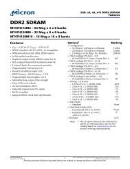
Figure 2-1 shows a block diagram of the DN3000k10.<br />
The DN3000k10 is a complete logic emulation system that enables ASIC or<br />
IP designers a vehicle to prototype logic and memory designs for a fraction<br />
of the cost of existing solutions. The DN3000k10 can be hosted in a 32/64-<br />
bit PCI/PCI-X slot, or can be used as a stand-alone device. A single<br />
DN3000k10 stuffed with five XC2V6000s can emulate up to 3 million gates<br />
of logic as measured by LSI. High I/O-count, 1152-pin, flip-chip BGA packages<br />
are employed. The FF1152 package has 824 I/Os, which allows for<br />
abundant connections to daughter connectors and external memories. A<br />
total of 437 test pins are provided on the top of the PWB via high-density<br />
connectors for logic analyzer-based debugging, or for pattern generator<br />
stimulus. Custom daughter cards such as the DN3k10SD can be mounted<br />
to these connectors as a means of interfacing the DN3000k10 to<br />
application-specific circuits. A reference 32-bit PCI target design and test<br />
bench is provided in Verilog at no additional cost.<br />
Smart Media<br />
Card<br />
16/32/64 Mbyte<br />
(FPGA configuration<br />
storage)<br />
RS232<br />
2<br />
32kx8 SRAM<br />
ATmega103L<br />
Flash-based µP<br />
FPGA<br />
Configuration<br />
Controller<br />
95288XL<br />
CPLD<br />
20<br />
FPGA<br />
Configuration<br />
+5V<br />
Switching<br />
Power<br />
Supply<br />
+3.3V (10A)<br />
+1.5V (10A)<br />
+5V<br />
-12V<br />
+12V<br />
+3.3V<br />
+1.5V<br />
FB<br />
SDRAM<br />
(168 pin DIMM Module)<br />
Up to 1GB x 64<br />
ECLK<br />
FPGA<br />
A<br />
XC2V6000<br />
(FF1152)<br />
145<br />
AF<br />
AB<br />
127<br />
FB<br />
110<br />
AE<br />
MB [226:0]<br />
115<br />
FPGA<br />
B<br />
XC2V6000<br />
(FF1152)<br />
BE<br />
89<br />
70<br />
A2D<br />
74<br />
FlowThrough/<br />
Pipelined<br />
SSRAM<br />
512k x 36<br />
ECLK<br />
ECLK<br />
FlowThrough/<br />
Pipelined<br />
SSRAM<br />
512k x 36<br />
70<br />
176<br />
BD<br />
A2D<br />
FlowThrough/<br />
Pipelined<br />
SSRAM<br />
512k x 36<br />
ECLK<br />
AB<br />
AE<br />
BD<br />
FB<br />
MB<br />
clocks<br />
AHDR<br />
BHDR<br />
DHDR<br />
EHDR<br />
57<br />
56<br />
41<br />
1<br />
75<br />
16<br />
75<br />
49<br />
58<br />
8<br />
Top of PWB<br />
Reset<br />
Control<br />
(test connectors)<br />
FPGA<br />
F<br />
XC2V6000<br />
(FF1152)<br />
EF<br />
102<br />
FPGA<br />
E<br />
XC2V6000<br />
(FF1152)<br />
ED<br />
152<br />
FPGA<br />
D<br />
XC2V6000<br />
(FF1152)<br />
ACLK<br />
BCLK<br />
CCLK<br />
DCLK<br />
ECLK<br />
config<br />
Roboclock<br />
PLL<br />
1<br />
Roboclock<br />
PLL<br />
2<br />
Clock<br />
Selection<br />
Jumpers<br />
or<br />
External<br />
Cable<br />
OSC<br />
X1<br />
OSC<br />
X2<br />
92<br />
32/64-Bit PCI/PCI-X<br />
FED<br />
84 70<br />
ECLK<br />
FlowThrough/<br />
Pipelined<br />
SSRAM<br />
512k x 36<br />
config<br />
rev 5/30/03<br />
Figure 2-1 DN3000k10 Block Diagram<br />
2-2 The DINI Group
DN3000k10 Features, Overview and General Description<br />
Easy<br />
Configuration<br />
via<br />
SmartMedia<br />
The configuration bit files for the FPGA are copied onto a 32-megabyte<br />
SmartMedia FLASH card (provided) and an on-board microprocessor<br />
controls the FPGA configuration process. Visibility into the configuration<br />
process is enhanced with an RS232 port. Sanity checks are performed automatically<br />
on the configuration bit files, helping to avoid the timeconsuming<br />
process of debugging the configuration process. FPGA configuration<br />
runs quickly at 48 MHz. Eight LEDs provide instant status and operational<br />
feedback. Two of these LEDs are connected to the CPLD and can be<br />
user-configured.<br />
FPGA — VirtexII (U11, U12, U20, U21, U22—A, B, D, E, F)<br />
The DN3000k10 contains two to five Virtex II FPGAs. They are called A, B,<br />
D, E, and F. The package is a flip chip fine-pitch BGA with 1152 pins<br />
(FF1152). The pitch on the pins is 1 mm. This isn’t important, but this pin<br />
density makes the PWB a bitch to layout. Keep that in mind if you try to<br />
make one of these at home. Most of the 824 I/O pins are utilized on the<br />
FF1152 package. The DN3000k10 can be stuffed with any combination of<br />
the 2V4000s, 2V6000s, and 2V8000s. The 2V3000 does come in an FF1152,<br />
but since it has fewer I/O pins, it should not be used. The standard speed<br />
grade we stuff is –4. We can use the –5 and –6 speed grades, but don’t fall<br />
out of your chair when you get the price. Note that Xilinx has cancelled<br />
plans for the 2V10000. Even though this part appears in some Xilinx literature,<br />
we have been told that the 2V8000 is the largest part that the<br />
process will handle. Don’t expect to see anything larger than the 2V8000<br />
until the 2003 time frame.<br />
What happened to C We struggled with the layout for many<br />
months, which gave the buffoons in marketing time to rethink what they<br />
asked for. As is normally the case with marketing, after a few drinks they<br />
decided to change the requirements. The FPGA that originally was in the C<br />
position was eliminated and replaced with the four SSRAMs and a SDRAM<br />
DIMM. So much work had been done to that point that those of us in engineering<br />
didn’t think it wise to re-label the FPGAs. That is why no FPGA_C<br />
exists.<br />
The following is a very brief overview of the VirtexII family. More information<br />
can be gleaned from the Virtex II Datasheet<br />
(VirtexII-Datasheet.pdf) and the VirtexII User’s Guide<br />
(VirtexII-UserGuide.pdf). Both files are on the CD-ROM supplied with<br />
the DN3000k10, but you are better off getting the latest versions from the<br />
Xilinx Web page (http://www.xilinx.com/). Make sure to get the latest<br />
errata sheet also.<br />
Flip-Flops and<br />
LUTs<br />
Figure 2-2 shows what Xilinx calls a slice. Each slice contains 2 flip-flops. A<br />
configurable logic block (CLB) contains 4 slices. The XC2V6000 is a 96 x 88<br />
grid of CLBs. Therefore, the XC2V6000 contains 67,584 flip-flops. This flipflop<br />
count does not include the six flip-flops contained in each I/O block.<br />
Each flip-flop has a 4 x 1 look up table (LUT). An LUT can do any Boolean<br />
function of the four inputs. The rest of the multiplexers allow for carry<br />
chains and other functions. An overview of the VirtexII Architecture is<br />
shown in Figure 2-3.<br />
DN3000k10 User’s <strong>Manual</strong> 2-3
DN3000k10 Features, Overview and General Description<br />
G<br />
inputs<br />
LUT<br />
D<br />
D Q<br />
FF/LAT<br />
CE<br />
CLK<br />
SR REV<br />
YQ<br />
BY<br />
MUXF5<br />
F5<br />
X<br />
LUT<br />
F<br />
inputs<br />
D<br />
DX<br />
D Q<br />
FF/LAT<br />
CE<br />
CLK<br />
SR REV<br />
XQ<br />
BX<br />
CE<br />
CLK<br />
SR<br />
Figure 2-2 General Slice Diagram<br />
Global Clock Mux<br />
DCM DCM IOB<br />
Configurable Logic<br />
Programmable I/Os<br />
CLB<br />
Block SelectRAM<br />
Multiplier<br />
Figure 2-3 VirtexII Architecture Overview<br />
2-4 The DINI Group
DN3000k10 Features, Overview and General Description<br />
Embedded<br />
Memory<br />
VirtexII has boatloads of embedded memory. The XC2V6000 contains 144,<br />
18-Kbit blocks. Each memory block can be configured as 16K x 1, 2K x 9,<br />
8K x 2, 1K x 18, 4K x 4 or 512 x 36. Remember that unused LUTs may also<br />
be used as memory. Xilinx refers to the embedded memory as Block<br />
SelectRAM, and to the LUT-based memory as Distributed Memory. The<br />
embedded memory is dual-ported and quite flexible. Virtually any type of<br />
memory can be constructed—FIFOs, dual-port RAMs, single-port RAMs, etc.<br />
The 18 Kb block SelectRAM dual-port memory consists of an 18 Kb storage<br />
area and two completely independent access ports, A and B. The structure<br />
is fully symmetrical, and both ports are interchangeable. See Figure 2-4<br />
for a diagram of the memory.<br />
18-Kbit Block SelectRAM<br />
DIA<br />
DIPA<br />
ADDRA<br />
WEA<br />
ENA<br />
SSRA<br />
CLKA<br />
DIB<br />
DIPB<br />
ADDRB<br />
WEB<br />
ENB<br />
SSRB<br />
CLKB<br />
Port A<br />
18 Kb<br />
Memory<br />
Array<br />
Port B<br />
DOA<br />
DOPA<br />
DOB<br />
DOPB<br />
Figure 2-4 Dual-Port Data Flows<br />
Data can be written to or read from either port in almost any combination.<br />
Each port is synchronous, with its own clock, clock enable, and write<br />
enable. Note that the read operation is also synchronous and requires a<br />
clock edge.<br />
We have found that a functional description of the memory is sufficient<br />
for the synthesis tools to recognize the memories and implement the<br />
embedded blocks. More on the synthesis issues in “Synthesis and Emulation<br />
Issues” on page 2-29.<br />
Multipliers<br />
VirtexII devices feature a large number of embedded 18-bit x 18-bit two’s<br />
complement embedded multipliers (see Figure 2-5). The XC2V6000<br />
contains 144 of these; the XC2V4000 contains 120. The embedded<br />
multipliers offer fast, efficient means to create 18-bit by 18-bit signed<br />
DN3000k10 User’s <strong>Manual</strong> 2-5
DN3000k10 Features, Overview and General Description<br />
multipliers. The multiplier blocks share routing resources with the Block<br />
SelectRAM memory, allowing for increased efficiency for many applications.<br />
Cascading of multipliers can be implemented with additional logic<br />
resources of VirtexII slices.<br />
Applications such as signed-signed, signed-unsigned, and unsignedunsigned<br />
multiplication, logical, arithmetic, and barrel shifters, two’s<br />
complement and magnitude return are easily implemented.<br />
We were surprised to find that the synthesis tools had no problem recognizing<br />
multipliers in Verilog and VHDL. So it appears that functional RTL is<br />
all that is necessary to use the embedded multipliers. More on the<br />
synthesis issues in “Synthesis and Emulation Issues” on page 2-29.<br />
18<br />
A<br />
18<br />
P = A • B<br />
36<br />
P<br />
B<br />
MULT18X18<br />
Figure 2-5 Embedded Multiplier<br />
I/O Issues<br />
Digitally Controlled Impedance (DCI) is supported on all pins. The resistors<br />
used for VRN and VRP are 51.1 ohms 1%. The PWB impedance is 60 ohms.<br />
So the Xilinx tools should be adjusted to reflect the fact that the reference<br />
resistors match the board impedance (and NOT half the resistance of the<br />
reference resistors). DCI is a very nice feature and we recommend you use<br />
it on all I/O signals. The correct IOATTRIBUTE standard for the UCF file is<br />
LVDCI_33.<br />
All VCCO pins are connected to +3.3 V. The VREF pins are used as I/Os, so the<br />
DN3000k10 does not support I/O standards that require VREF. No signals<br />
have a V TT (Board Termination Voltage). So the I/O standards supported<br />
are:<br />
LVTTL — Low-Voltage TTL<br />
The low-voltage TTL, or LVTTL, standard is a general-purpose EIA/JESDSA<br />
standard for 3.3 V applications that use the LVTTL input buffer and a Push-<br />
Pull output buffer. The standard requires a 3.3 V input and output source<br />
voltage (V CCO ) but does not require the use of a reference voltage (V REF )<br />
or a termination voltage (V TT ).<br />
LVCMOS33 — 3.3 Volt Low-Voltage CMOS<br />
This standard is an extension of the LVCMOS standard (JESD8. –5). It is used<br />
in general-purpose 3.3 V applications. The standard requires a 3.3 V<br />
input/output source voltage (V CCO ) but does not require the use of a reference<br />
voltage (V REF ) or a termination voltage (V TT ).<br />
PCI-X — Peripheral Component Interface<br />
The PCI standard specifies support for 33 MHz, 66 MHz and 133 MHz PCI<br />
2-6 The DINI Group
DN3000k10 Features, Overview and General Description<br />
bus applications. It uses a LVTTL input buffer and a Push-Pull output buffer.<br />
This standard does not require the use of a reference voltage (V REF ) or a<br />
board termination voltage (V TT ); however, it does require 3.3 V input<br />
output source voltage (V CCO ).<br />
LVDS is supported on some pins to the 200–pin connectors. See “The 200<br />
Pin Connectors: J28, J25, J26” on page 8–5.<br />
Bitstream<br />
Encryptions<br />
VirtexII devices have on-chip decryption circuitry that can be enabled to<br />
make the configuration bitstream (and thus the whole logic design)<br />
secure. Ultimately, you will be able to encrypt the bitstream in the Xilinx<br />
software, and the VirtexII chip will perform the reverse operation,<br />
decrypting the incoming bitstream and internally recreating the intended<br />
configuration. The DN3000k10 has a battery socket to support this<br />
function.<br />
Encrypting the bitstream is important if you want to use the DN3000k10<br />
as a platform to demonstrate intellectual property (IP) but don’t want<br />
anybody reverse engineering the bitstream in an attempt to steal the<br />
design.<br />
NOTE: It is possible to recreate a design from the configuration<br />
bitstream!<br />
This method provides a very high degree of design security. Without<br />
knowledge of the encryption/decryption key or keys, potential pirates<br />
cannot use the externally intercepted bitstream to analyze, or even to<br />
clone the design. System manufacturers can be sure that their VirtexII<br />
implemented designs cannot be copied and reverse engineered.<br />
The VirtexII devices store the internal decryption keys in a few hundred<br />
bits of dedicated RAM, backed up by a small externally-connected battery<br />
(BTI on the circuit board). At less than100 nA per load, the endurance of<br />
the battery is limited only by its shelf life.<br />
The method used to encrypt the data is Data Encryption Standard (DES).<br />
This is an official standard supported by the National Institute of Standards<br />
and Technology (NIST) and the U.S. Department of Commerce. DES is<br />
a symmetric encryption standard that utilizes a 56-bit key. Because of the<br />
increased sophistication and speed of today’s computing hardware, single<br />
DES is no longer considered to be secure. However, the Triple Data Encryption<br />
Algorithm (TDEA), otherwise known as triple DES, is authorized for<br />
use by U.S. federal organizations to protect sensitive data, and is used by<br />
many financial institutions to protect their transactions. Triple DES has yet<br />
to be cracked. Both DES and Triple DES are available in VirtexII devices.<br />
What DES Is<br />
DES and Triple DES are symmetric encryption algorithms. This means that<br />
the key to encrypt and the key to decrypt are the same. The security of the<br />
data is kept by keeping the key secret. This contrasts to a public key<br />
system, like RSA or PGP. One thing to note is that VirtexII devices use DES in<br />
Cipher Block Chaining mode. This means that each block is combined with<br />
DN3000k10 User’s <strong>Manual</strong> 2-7
DN3000k10 Features, Overview and General Description<br />
the previous encrypted block for added security. DES uses a single 56-bit<br />
key to encrypt 64-bit blocks one at a time.<br />
This section is being updated mid-March 2002. At this time, only the Xilinx<br />
tools version 4.2 (or a patched 4.1.03) support the encryption function of<br />
the Virtex II devices. There are various erratas, updates, and white papers<br />
available at the Xilinx web site (http://www.xilinx.com). Also, our most<br />
updated information regarding using Virtex II devices with encryption can<br />
be found at our web site at:<br />
http://www.dinigroup.com/products/3000k10ns.html.<br />
As of now, encryption is fully supported using the JTAG chain programming<br />
the parts. Encryption using SmartMedia programming will be<br />
supported soon. We have found several undocumented features of the<br />
Xilinx Virtex II parts with SelectMAP programming that we are now<br />
working to accommodate.<br />
Note that encryption and partial reconfiguration are mutually exclusive.<br />
You can do one or the other, but not both. There is also a previous errata<br />
on the sizes of bit files generated for Virtex II parts being larger than the<br />
originally-intended size by approximately 10%. This does NOT apply to<br />
encrypted bitstreams. The size of an encrypted bit file is the originallyintended<br />
size.<br />
For more detailed information regarding Virtex II parts and encryption,<br />
see our Encrypted Bitstream documentation at:<br />
http://www.dinigroup.com/products/3000k10ns.html.<br />
Programming Encrypted Bitstreams Using JTAG<br />
1. Creating the Encrypted Bitstreams<br />
A new option has been added to the Xilinx “bitgen” utility for all<br />
devices that support encryption. Add the “-g Encrypt:Yes” option<br />
to the “bitgen” command line (see Xilinx User’s Guide) to create an<br />
encrypted bitstream.<br />
Two files will be created. The first is the encrypted bit file. the second<br />
is a key file, “.nky” (which you can specify using the “-g Key-<br />
File:” option). The key file contains the<br />
encrypt/decrypt keys used to encrypt/decrypt the bit file.<br />
2. Programming the Key File<br />
Using the Xilinx iMPACT tool and a JTAG programmer, program the<br />
key file “.nky” into the FPGA that will decrypt the encrypted bitstreams.<br />
Make sure that a +3 V 2032-type lithium coin battery is<br />
installed in BT1 prior to programming. The battery is required for<br />
key-retention.<br />
3. Programming the Encrypted Bitstreams<br />
Using the Xilinx iMPACT tool and a JTAG programmer, program the<br />
encrypted bitstreams into the FPGA. The FPGA will then decrypt the<br />
bitstream using the previously-programmed decryption keys.<br />
2-8 The DINI Group
DN3000k10 Features, Overview and General Description<br />
Programming Encrypted Bitstreams Using SmartMedia<br />
The procedure for this is very similar to the procedure for JTAG. However,<br />
support for this is not complete and will be coming shortly. For more<br />
detailed information, contact us directly or visit our web site at:<br />
http://www.dinigroup.com/products/3000k10ns.html.<br />
The Battery The DN3000k10 has a socket for a battery, BT1. The socket uses a +3 V,<br />
2032 coin-style lithium battery. Don’t eat the battery. Most lithium<br />
batteries are rated at about 200 mAh, so at 100 nA, the battery should last<br />
for 5 years or so.<br />
µP and FPGA Configuration<br />
The DN3000k10 has an ATmega128L microprocessor (µP) that is used to<br />
control the configuration process (U3). The amount of internal SRAM<br />
(4 Kbytes) was not large enough to hold the FAT needed for SmartMedia,<br />
so an external 32 k x 8 SRAM was added. The address latching function is<br />
done via an LVX373 (U6).<br />
The microprocessor has the following responsibilities:<br />
• Reading the SmartMedia card<br />
• Configuring the VirtexII FPGA<br />
• Executing DN3000k10 self tests.<br />
Other than FPGA configuration, the µP has no responsibilities. Less than<br />
25% of the 128 Kbytes of FLASH is used for FPGA configuration and utilities,<br />
so you are welcome to use the rest of the resources of the µP for your<br />
own purposes. Instructions for customizing the µP are contained in the file<br />
Custom_Atmega128L.pdf. This file is on the CD-ROM, or it can be downloaded<br />
from the DINI Group web page.<br />
REMEMBER: You can use the microprocessor for your own purposes!<br />
We ship a programming cable for the ATmega128L with the DN3000k10.<br />
Updates to the code will be posted on our web site. If you wish to do your<br />
own development you will need the compiler, which we do not ship with<br />
the product. The compiler is available from IAR (http://www.iar.com/).<br />
The part number is EWA90PCUBLV150.<br />
Note that if you are willing to program the FPGA with the JTAG or serial<br />
cable, the CLPD and the µP have no function. In this case you can use all of<br />
the resources of the µP for your own purposes.<br />
The µP: Some<br />
Details<br />
The ATmega128L is gross overkill for the FPGA configuration function. The<br />
datasheet and user’s manual are on the CD-ROM that was shipped with the<br />
DN3000k10. The file names are ATmega128_UM.pdf and<br />
atmega128_DS.pdf. But if you intend to use the µP for your own<br />
purposes, you should check the Atmel web page to get a copy of the latest<br />
user’s manual, datasheet, and erratas. The Atmel web page is<br />
DN3000k10 User’s <strong>Manual</strong> 2-9
DN3000k10 Features, Overview and General Description<br />
http://www.eu.atmel.com/atmel/. The ATmega128L is under the section<br />
called “Flash Microcontroller, AVR 8-Bit RISC.” Most of the features are<br />
unused. A variety of test headers allow for possible use of these features.<br />
Each header and the various possible functions are described in the<br />
sections that follow. Figure 2-6 is a block diagram of the ATmega128L and<br />
its various interfaces on the DN3000k10.<br />
+3.3V Noise<br />
Conditioner<br />
AREF<br />
AVCC<br />
A/D Inputs or<br />
User I/O<br />
µP<br />
JTAG<br />
J20<br />
General<br />
Purpose I/O<br />
J15<br />
CSF*<br />
FWRTSM<br />
DOUTBSYF<br />
D [7:0]<br />
CSA*<br />
FPGA<br />
F<br />
(U22)<br />
J30<br />
RS232<br />
Connector<br />
J34<br />
J2<br />
Config.<br />
Jumpers<br />
top<br />
bottom<br />
Card<br />
Inserted<br />
JMPR [2:0]<br />
RS232<br />
Level<br />
Translator<br />
ICL3221<br />
Programming<br />
Header<br />
J18<br />
J16<br />
Programming<br />
Header<br />
T x<br />
R x<br />
Smart<br />
Media<br />
Reset<br />
Switch<br />
Atmel AVR<br />
ATmega128L<br />
µP<br />
128kbytes FLASH<br />
4kbytes SRAM<br />
4kbytes EEPROM<br />
U3<br />
32.768MHz<br />
Crystal<br />
TOD Y1<br />
S1<br />
A/D<br />
+5V<br />
+3.3V<br />
+1.5V<br />
WR*<br />
RD*<br />
ALE<br />
µPADDR[14:8]<br />
U2<br />
Reset & Power<br />
Threshold Detection<br />
X3<br />
SRAM<br />
32kx8<br />
U6<br />
48MHz<br />
Osc<br />
µPAD[7:0]<br />
µPADDR[7:0]<br />
8 MHz<br />
PWR RST-<br />
XC95288XL<br />
CPLD<br />
U13<br />
6<br />
DOUTBSYA<br />
CSB*<br />
DOUTBSYB<br />
CSD*<br />
DOUTBSYD<br />
CSE*<br />
DOUTBSYE<br />
LED[3:0]<br />
4<br />
LED4<br />
U17<br />
U19<br />
FPGA<br />
A<br />
(U11)<br />
FPGA<br />
B<br />
(U12)<br />
FPGA<br />
D<br />
(U21)<br />
FPGA<br />
E<br />
(U20)<br />
LED5<br />
LOCK1#<br />
LOCK2#<br />
Figure 2-6 Block Diagram of ATmega128L and DN3000k10 Interfaces<br />
2-10 The DINI Group
DN3000k10 Features, Overview and General Description<br />
A/D: Analog to<br />
Digital<br />
Converter<br />
J20 connects to the A/D inputs of the ATmega128L. Header pins for AVCC<br />
and AREF are also provided if you wish to use AVCC elsewhere, or want to<br />
provide a cleaner AREF to the µP. The odd pins of J20 are grounded,<br />
making for a clean connection with an IDC cable. The eight A/D pins<br />
(UPADC[7:0]) may also be used as TTL I/O. UPADC[7:4] also may be used<br />
to connect to the JTAG port of the ATmega128L (See “ATmega128L JTAG<br />
Interface” on page 2–12.).<br />
According to the Atmel documentation, the following features apply to<br />
the A/D:<br />
• 10-bit Resolution<br />
• 0.5 LSB Integral Non-linearity<br />
• ±2 LSB Absolute Accuracy<br />
• 8 Multiplexed Single Ended Input Channels<br />
• 7 Differential Input Channels<br />
• 2 Differential Input Channels with Optional Gain of 10x and 200x<br />
• Optional Left Adjustment for ADC Result Readout<br />
• 0–VCC ADC Input Voltage Range<br />
• Selectable Internal 2.56 V ADC Reference Voltage<br />
• Free Running or Single Conversion Mode<br />
• Interrupt on ADC Conversion Complete<br />
• Sleep Mode Noise Canceller<br />
The J20 Connections are shown in Figure 2-7. The AVCC port connections<br />
are shown in Figure 2-8.<br />
+3.3 V is filtered via a 100µH (L2) inductor. The output is AVCC (analog<br />
VCC). Inductor L2 is rated 120 ma. VREF is the result of a resistor division of<br />
R13 and R7. The DN3000k10 is shipped with 30 ohm, 1% resistors (size<br />
1210) in these locations, resulting in an AREF voltage of AVCC/2 or approximately<br />
1.65 V. If you wish to supply your own AVCC and VREF voltages,<br />
J20<br />
1<br />
3<br />
5<br />
7<br />
9<br />
11<br />
13<br />
15<br />
17<br />
19<br />
HDR10X2<br />
2<br />
4<br />
6<br />
8<br />
10<br />
12<br />
14<br />
16<br />
18<br />
20<br />
(TCK)<br />
(TMS)<br />
(TDO)<br />
(TDI)<br />
AVCC<br />
AREF<br />
UPADC0<br />
UPADC1<br />
UPADC2<br />
UPADC3<br />
UPADC4<br />
UPADC5<br />
UPADC6<br />
UPADC7<br />
+3.3V<br />
61<br />
60<br />
59<br />
58<br />
57<br />
56<br />
55<br />
54<br />
52<br />
21<br />
PF0/ADC0<br />
PF1/ADC1<br />
PF2/ADC2<br />
PF3/ADC3<br />
PF4/ADC4/TCK<br />
PF5/ADC5/TMS<br />
PF6/ADC6/TDO<br />
PF7/ADC7/TDI<br />
VCC<br />
VCC<br />
µP<br />
JTAG<br />
Interface<br />
U3<br />
ATmega103L-4AC<br />
Figure 2-7 J20 Analog to Digital Connections<br />
DN3000k10 User’s <strong>Manual</strong> 2-11
DN3000k10 Features, Overview and General Description<br />
AVCC<br />
L2<br />
100µH<br />
+3.3V<br />
U3<br />
ALE<br />
RD<br />
WR<br />
AREF<br />
AGND<br />
AVCC<br />
AD0/PA0<br />
AD1/PA1<br />
AD2/PA2<br />
43<br />
34<br />
33<br />
62<br />
63<br />
64<br />
51<br />
50<br />
49<br />
ALE<br />
RD-<br />
WR-<br />
AREF<br />
AVCC<br />
UPAD0<br />
UPAD1<br />
UPAD2<br />
R13<br />
30.0 1% 1210<br />
R7<br />
30.0 1% 1210<br />
C27<br />
0.1µF<br />
Figure 2-8 AVCC Connections<br />
remove L2, R13, and R7, and input your signals on J20 pins 18 and 20.<br />
Remember that the ATmega128 also has an internal reference voltage of<br />
2.56 V. If you use the internal 2.56 V reference, leave C27 stuffed. Atmel<br />
documents state that externally decoupling AREF will improve the noise<br />
performance of the A/D.<br />
J15: Unused µP<br />
Connections<br />
J15 contains connections to the ATmega128L that were not used elsewhere.<br />
These ten connections can be used for external TTL connections to<br />
the µP, externally generated interrupts, or any other function that the<br />
ATmega128L supports on these pins. Remember that the ATmega128L is<br />
not +5 V tolerant, so if you attach external TTL signals to these pins, the<br />
voltage level of these signals must not exceed +3.3 V.<br />
The J15 schematic is shown in Figure 2-9.<br />
ATmega128L JTAG Interface<br />
The ATMega128L processor has a JTAG interface that can be used for onchip<br />
debugging, real-time emulation, and programming of FLASH,<br />
EEPROM, fuses, and Lock Bits. In order to take advantage of the JTAG interface,<br />
you must have the Atmel AVR JTAG ICE kit (part number ATAVR-<br />
JTAGICE) and AVR studio software that Atmel provides free at<br />
www.atmel.com. The JTAG interface for the ATmega128L can be accessed<br />
through four pins (TCK, TMS, TDO and TDI) on header J20 of the<br />
DN3000k10 (see Figure 2-10).<br />
2-12 The DINI Group
DN3000k10 Features, Overview and General Description<br />
J15<br />
1 2<br />
3 4<br />
5 6<br />
7 8<br />
9 10<br />
11 12<br />
13 14<br />
15 16<br />
17 18<br />
19 20<br />
21 22<br />
23 24<br />
25 26<br />
HDR13X2<br />
UPINT5<br />
UPINT6<br />
UPINT7<br />
SS<br />
SO<br />
SI<br />
SCK<br />
SMCD-<br />
SMWP1-<br />
UP5<br />
UP6<br />
UP7<br />
UP8<br />
UP9<br />
UP10<br />
BRXD<br />
BTXD<br />
JMPR0<br />
JMPR1<br />
JMPR2<br />
UPINT5<br />
UPINT6<br />
UPINT7<br />
25<br />
26<br />
27<br />
28<br />
29<br />
30<br />
31<br />
32<br />
2<br />
3<br />
4<br />
5<br />
6<br />
7<br />
8<br />
9<br />
PD0/INT0<br />
PD1/INT1<br />
PD2/INT2<br />
PD3/INT3<br />
PD4/IC1<br />
PD5<br />
PD6/T1<br />
PD7/T2<br />
PE0/(PDI/RXD)<br />
PE1/(PDO/TXD)<br />
PE2/AC+<br />
PE3/AC-<br />
PE4/INT4<br />
PE5/INT5<br />
PE6/INT6<br />
PE7/INT7<br />
Figure 2-9 J15: Unused µP Connections<br />
J20<br />
1<br />
3<br />
5<br />
7<br />
9<br />
11<br />
13<br />
15<br />
17<br />
19<br />
HDR10X2<br />
2<br />
4<br />
6<br />
8<br />
10<br />
12<br />
14<br />
16<br />
18<br />
20<br />
TCK<br />
TMS<br />
TDO<br />
TDI<br />
AVCC<br />
AREF<br />
Figure 2-10 ATmega128L JTAG Interface<br />
DN3000k10 User’s <strong>Manual</strong> 2-13
DN3000k10 Features, Overview and General Description<br />
Programming<br />
the<br />
ATmega128L<br />
(U3)<br />
A cable used to reprogram the ATmega128L is shipped with the<br />
DN3000k10. You will need to reprogram the ATmega128L if we update<br />
the code or you intend to use the processor for your own application. J18<br />
is used for this purpose.<br />
Figure 2-11 illustrates J18.<br />
BRXD<br />
PWRRST-<br />
SCK<br />
BTXD<br />
J18<br />
1<br />
3<br />
5<br />
7<br />
9<br />
HDR5X2<br />
2<br />
4<br />
6<br />
8<br />
10<br />
+3.3V<br />
Detailed Instructions<br />
1. Download the latest update for the processor and CPLD at www.dinigroup.com<br />
(file uP_CPLD.zip).<br />
2. You will first need to reprogram the CPLD. Please see “CPLD—<br />
XC95288XL” on page 2-16 for instructions (use the file<br />
DNk10S_CPLD.jed that can be found in the downloaded zip file.<br />
3. Next, you will program the processor (ATmetga128L). Connect the<br />
AVR cable that was shipped with the DN3000k10 to header J18 with<br />
the red/purple wire on the cable connected to pin 1 and connect the<br />
other end to the serial port of your PC.<br />
4. In order to program the processor, you will need to install AVR Studio<br />
that is included on the Atmel CD that was shipped with the<br />
DN3000k10. This software can also be downloaded at<br />
www.atmel.com.<br />
5. From the Windows START menu, choose PROGRAMS–>Atmel AVR Studio<br />
x.xx (where x.xx is the version number).<br />
6. Once AVR Studio is open, select TOOLS–>STK500/AVRISP/JTAG ICE and<br />
a new window should appear with the title STK500. At the bottom of<br />
the STK500 window, if you see:<br />
Detecting…FAILED!<br />
Figure 2-11 J18 Schematic<br />
that means either there is no power on the DN3000k10, there is<br />
another program open that is using the serial port, or the serial cable<br />
connecting the AVR tool is not connected properly. If this happens,<br />
you should close down the window titled STK500, correct the situation,<br />
and then select TOOLS–>STK500/AVRISP/JTAG ICE again. You<br />
will not be able to continue unless you see something very similar to<br />
the following at the bottom of the STK500 window:<br />
2-14 The DINI Group
DN3000k10 Features, Overview and General Description<br />
Detecting…AVRISP found on COM1:<br />
Getting revisions…HW: 0x01, SW Major: 0x01, SW<br />
Minor: 0x07…OK<br />
7. On the PROGRAM tab, select the ATmega128 under the DEVICE drop<br />
down menu, and in the FLASH section where it says INPUT HEX FILE,<br />
browse and select the file DN3000k10_128.a90 that can be found in<br />
the downloaded zip file (uP_CPLD.zip) from the Dini Group website.<br />
To program the device all you need to do is hit the PROGRAM button<br />
in the FLASH section. When the programming is complete (it takes<br />
about 45 seconds) you should see a message at the bottom of the<br />
window that looks something like this:<br />
Detecting…AVRISP found on COM1:<br />
Getting revisions…HW: 0x01, SW Major 0x01, SW<br />
Minor: 0x07…OK<br />
Reading FLASH input file…OK<br />
Setting device parameters, serial programming<br />
mode…OK<br />
Entering programming mode…OK<br />
Erasing device…OK<br />
Programming FLASH using block mode…100% OK<br />
Leaving programming mode…OK<br />
8. After programming the processor, close all AVR Studio windows and<br />
setup the serial port according to the section titled “Setting up the<br />
Serial Port (J30/J34 — RS232 Port)” on page 2-21. Please note that in<br />
this situation, connecting the serial port is mandatory and the FPGA<br />
cannot be configured via the SmartMedia card until you have completed<br />
all the instructions in this section.<br />
9. Reset the DN3000k10 by pressing S1. After about 10 seconds, you<br />
should see the following in the HyperTerminal window:<br />
**********NEED FPGA STUFFING INFORMATION*********<br />
Enter number of FPGAs on Board (1–6):<br />
Using the keyboard, enter the number of FPGAs on the board (should<br />
be between 1 and 5 for the DN3000k10). After you have entered this,<br />
you should see the following menu:<br />
1) Virtex II 1000 (FG456)<br />
2) Virtex II 6000 (FF1152)<br />
3) Virtex II 4000 (FF1152)<br />
4) Virtex II 3000 (FG676)<br />
Please enter selection (1–4) for FPGA F:<br />
Enter the type of FPGA that is stuffed on your DN3000k10. If you enter<br />
the wrong type of FPGA or the incorrect number of FPGAs on the<br />
board, then you will need to reprogram the processor and follow<br />
these steps again.<br />
DN3000k10 User’s <strong>Manual</strong> 2-15
DN3000k10 Features, Overview and General Description<br />
10. The processor and the CPLD are now ready to configure the FPGA(s).<br />
Please see the section titled “Starting SelectMAP Configuration” on<br />
page 2-25 for further instructions.<br />
CPLD—<br />
XC95288XL<br />
Some non-volatile logic is needed to handle the counters and state<br />
machines associated with the high-speed interface to the SmartMedia<br />
card. We used an XC95288XL CPLD from Xilinx for this function. The<br />
datasheet is on the CD-ROM and is titled xc95288xl.pdf. Approximately<br />
90% of the resources of this device are utilized, so 10% are available for<br />
your own purposes. The Verilog source for the CPLD is provided on the CD–<br />
ROM. The file name is CPLD.V.<br />
The CPLD performs the following functions:<br />
• Level Translation and logic inversion for LED[5:0], LOCK_N[2:1]<br />
• µP SRAM Interface:<br />
– µP upper/lower address latch for 32K x 8 SRAM (U5):<br />
UPADDR[14:0]<br />
– SRAMCS–<br />
• Interface to ATmega128L µP<br />
– Data Bus: UPAD[7:0]<br />
– Control: ALE, RD–, WR–<br />
– Clock: CPUCLK<br />
• Interface to FPGA configuration signals<br />
– PROG–, DOUTBSYF, INITF–, DONEF<br />
– M[2:0]<br />
– SelectMap Interface<br />
+ Data Bus: {D[7:1], DIND0F}<br />
+ Chip Select: CSF–<br />
+ Read/Write: FWRTSM–<br />
– JTAG: FTMS, FTDO, FTDI, FTCK<br />
• Interface to SmartMedia Card<br />
– Data Bus: SMRTMED[7:0]<br />
– Control: SMCLE, SMALE, SMWE–, SMWP–, SMCE–, SMRE–,<br />
RDYBUSY–<br />
• Interface to Serial FPGA Configuration Cable:<br />
– C_DONE, C_DIN, C_PROG–, C_INIT–, C_CCLK<br />
We may periodically update the CPLD. The CPLD can be reprogrammed<br />
using the Xilinx JTAG cable supplied with the DN3000k10. The connections<br />
are on the 90° header on the top of the PWB labeled J16. The relevant<br />
signals and the connections to J16 are listed in Table 2-1. Figure 2-12<br />
shows the location of J16. With the exception of V CC and GND, you will find<br />
that the signals are placed on the connector in the same order as the JTAG<br />
cable. A schematic of J16 is shown in Figure 2-13.<br />
2-16 The DINI Group
DN3000k10 Features, Overview and General Description<br />
Table 2-1 Signals and Connections to J16<br />
JTAG Cable Color J16 Signal Name J16 Pin<br />
VCC Red +3.3 V 1, 2, 3, or 4<br />
GND Black GND 5, 6, 17, 19, 21 or 24<br />
TCK Yellow CPLD_TCK 8<br />
TDO Purple CPLD_TDO 10<br />
TDI White CPLD_TDI 12<br />
TMS Green CPLD_TMS 14<br />
J16<br />
Figure 2-12 Location of J16 on the DN3000k10<br />
DN3000k10 User’s <strong>Manual</strong> 2-17
DN3000k10 Features, Overview and General Description<br />
+3.3V<br />
C_CCLK<br />
C_DONE<br />
C_DIN<br />
C_PROG-<br />
C_INIT-<br />
J16<br />
1 2<br />
3 4<br />
5 6<br />
7 8<br />
9 10<br />
11 12<br />
13 14<br />
15 16<br />
17 18<br />
19 20<br />
21 22<br />
23 24<br />
HDR12x2 90 DEG M<br />
+3.3V<br />
CPLD_TCK<br />
CPLD_TDO<br />
CPLD_TDI<br />
CPLD_TMS<br />
FTCK<br />
FTDO<br />
FTDI<br />
FTMS<br />
Figure 2-13 J16 CPLD JTAG Configuration, FPGA Serial<br />
Configuration and FPGA JTAG Configuration<br />
Some Miscellaneous Notes on the CPLD<br />
X3 is a 48 MHz oscillator. This part is soldered down to the PWB and is not<br />
intended to be user-configurable. The 48 MHz is divided down to 8 MHz<br />
in the CPLD to provide the clock for the ATmega128L µP. The processor<br />
clock signal is labeled CPUCLK (and BCPUCLK) on the schematic, and may<br />
have a note that describes the frequency as 4 MHz. Initially, we used an<br />
ATmega103L instead of the ATmega128L. The ATmega103L maximum<br />
frequency was 4 MHz.<br />
The 48 MHz is used directly for the state machines in the CPLD for controlling<br />
the interface to the SmartMedia card. The frequency of 48 MHz is<br />
interesting because it is the closest frequency to 50 MHz that can be<br />
divided by an integer to get 8 MHz. The frequency 50 MHz is the fastest<br />
that the Xilinx VirtexII parts can be configured with SelectMap without<br />
wait states. So FPGA configuration using SelectMap occurs at very nearly<br />
the fastest theoretical speed.<br />
Serial and JTAG configuration of the VirtexII FPGA are back off positions<br />
only—that is why those signals are connected to the CPLD. Xilinx has a<br />
long history of botching the configuration method in new FPGA families,<br />
so we made sure we had all possible options available.<br />
If you want to use 100% of the CPLD and µP for your own purposes, you<br />
can configure the FPGA using the JTAG cable.<br />
The 48 MHz clock can be divided down in the CPLD and used to drive the<br />
PWB clock network. See Chapter 4 for a more detailed description of this<br />
option.<br />
2-18 The DINI Group
DN3000k10 Features, Overview and General Description<br />
LOCK_N[2:1] are the logical invert of LOCK[2:1]. The lock LEDs should<br />
go on when the respective RoboclockII PLLs are locked.<br />
Notes on Header J16<br />
SelectMap using the SmartMedia card is the best way to configure the<br />
FPGA. Two other options exists if, for some reason, the SmartMedia media<br />
method is not working.<br />
1. Serial Programming Using the Cable. Header J16 has the 5 serial connections<br />
that are used to configure the FPGA using the serial method.<br />
Table 2-4 has the pinouts. Note that this is a back-off position to<br />
SmartMedia and JTAG and should only be used in dire circumstances.<br />
Note also that header J17 will need to change to reflect “slave-serial”<br />
configuration.<br />
Table 2-2 FPGA Serial Configuration Header<br />
Name on<br />
Schematic:<br />
Name on<br />
Cable<br />
Cable Color<br />
Header Pin<br />
C_CCLK CCLK yellow J16.7<br />
C_DONE D/P blue J16.9<br />
C_DIN DIN green J16.11<br />
C_PROG– PROG orange J16.13<br />
C_INIT– (none) (none) J16.15<br />
GND GND black J16.5, J16.17,<br />
J16.19, J16.21,<br />
J16.6, J16.24<br />
VCC +3.3V red J16.1, J16.2,<br />
J16.3, J16.4<br />
2. JTAG Programming.<br />
The JTAG connection can be used to configure the FPGA and can also<br />
be used to connect the ChipScope ILA Logic Analyzer<br />
(www.xilinx.com/xlnx/xil_prodcat_product.jsptitle=chipscope_ila)<br />
or other solutions such as the Bridges2silicon system (see<br />
www.bridges2silicon.com). The JTAG method of configuration should<br />
be used if the SmartMedia method isn’t working. Remember that a<br />
DN3000k10 User’s <strong>Manual</strong> 2-19
DN3000k10 Features, Overview and General Description<br />
different bit file is necessary — the bit file must use the JTAG clock for<br />
configuration. Table 2-3 has the pinouts.<br />
Table 2-3 FPGA JTAG Configuration Header<br />
Name on<br />
Schematic<br />
Name on<br />
Cable<br />
Cable Color<br />
Header Pin<br />
FTCK TCK yellow J16.16<br />
FTDO TDO purple J16.18<br />
FTDI TDI white J16.20<br />
FTMS TMS green J16.22<br />
GND GND black J16.5, J16.17,<br />
J16.19, J16.21,<br />
J16.6, J16.24<br />
VCC +3.3V red J16.1, J16.2,<br />
J16.3, J16.4<br />
SelectMAP<br />
Configuration<br />
Instructions<br />
The FPGA on the DN3000k10 can be configured in SelectMAP mode using<br />
a Smart Media card. SelectMAP configuration is the easiest and quickest<br />
way to configure the FPGA. The DN3000k10 is shipped with two 32 MB<br />
Smart Media cards. One of these Smart Media cards contains a reference<br />
design bit file produced for SelectMAP configuration, and a file main.txt<br />
that sets options for the configuration process (for description of options,<br />
see “Creating Main Configuration File main.txt” on page 2-23). This Smart<br />
Media card has been marked as read-only by the silver, circular sticker on<br />
the card. The other Smart Media card is empty and is for use with your<br />
own designs. To configure the FPGA with the reference design, please skip<br />
to “Starting SelectMAP Configuration” on page 2-25.<br />
Creating Bit Files for SelectMAP<br />
Create bit files with Xilinx 3.3i with service pack 8 or Xilinx ISE 4.x<br />
• Use Xilinx 3.3i with service pack 8 and the patch for VirtexII (see<br />
http://support.xilinx.com/techdocs/11805.htm) or Xilinx ISE 4.<br />
For Xilinx 3.3i Design Manager:<br />
• After creating a project in Xilinx, go to the menu<br />
Design/Options and choose Edit Options for<br />
Configuration and uncheck the box. Enable the Power Down<br />
Status pin (Done pin) on the Configuration tab. Also<br />
make sure that on the Startup tab, the Startup Clock is CCLK.<br />
For Xilinx ISE 4.x Design Manager:<br />
• After creating a project in Xilinx, go to the menu<br />
Design/Options and choose Edit Options for Configuration<br />
and go to the Startup tab and make sure the Startup<br />
Clock is CCLK; on the Readback tab select SelectMap.<br />
2-20 The DINI Group
DN3000k10 Features, Overview and General Description<br />
For Xilinx ISE 4.x Project Navigator<br />
• NOTE: All the bitgen options are set correctly by default; however,<br />
you may want to double-check a few of the options. After<br />
creating a project and adding your source file, right-click on Generate<br />
Programming File in the Process View window.<br />
Select the Startup Options tab and make sure that the Startup<br />
Clock is set to CCLK. Select the Configuration Options<br />
tab and make sure Configuration Pin Powerdown has a value<br />
of Pull Up.<br />
Setting up the Serial Port (J30/J34 — RS232 Port)<br />
J30/J34 is for an RS232 connection to a terminal. An ICL3221 (U18)<br />
provides voltage translation to RS232 levels. A cable that converts the<br />
10-pin header to a DB9 is shipped with the DN3000k10. This cable comes<br />
packaged with a bracket attached. Remove the bracket to eliminate the<br />
possibility of it falling on the DN3000k10, which could short signals and<br />
damage the board. After you have removed the bracket, plug the cable<br />
into J30. J30 is not keyed—so make sure you get the orientation correct.<br />
Pin 2 is clearly labeled. Pin 1 is opposite of Pin 2, and Pin 1 is identified<br />
with a dot. Figure 2-14 is a cutout from the assembly drawing, and shows<br />
the location of J30 and Pin 1, and J34. J34 on the back of the DN3000k10<br />
can also be used for RS232 communication. This header is not normally<br />
stuffed. J34 is useful is a daughter card is installed that obstructs access to<br />
J30. J34 has the same pin out as J30.<br />
A female-to-female RS232 cable is provided with the DN3000k10. This<br />
cable will attach directly to the RS232 port of a PC. We get our cables from<br />
Jameco (http://www.jameco.com).The part number is 132345. Male-tofemale<br />
extension cables are part number 25700.<br />
The RS232 port is configured with the following parameters:<br />
Bits per second:9600<br />
Data bits:8<br />
Parity:None<br />
Stop Bits:1<br />
FLow control:None<br />
Terminal Emulation:VT100<br />
We use the Windows-based program HyperTerminal (Hypertrm.exe).<br />
The configuration file DN3000k10.ht is supplied on the CD-ROM or can be<br />
downloaded from our web page.<br />
Users have the option of connecting the serial port if they wish to see any<br />
messages during the configuration process.<br />
NOTE: It is NOT mandatory to have the serial port connection in order to<br />
configure the FPGA in SelectMAP mode. However, if an error occurs during<br />
the configuration, then without a serial port connection the user will not<br />
be able to see any error messages. In addition, without a serial port<br />
connection, a user cannot select any Main Menu options after the configuration<br />
process is complete.<br />
DN3000k10 User’s <strong>Manual</strong> 2-21
DN3000k10 Features, Overview and General Description<br />
T<br />
O<br />
P<br />
S<br />
IDE<br />
V<br />
IE<br />
W<br />
J30<br />
Pin 1<br />
J34<br />
Pin 1<br />
B<br />
O<br />
T<br />
T<br />
O<br />
M<br />
S<br />
I<br />
D<br />
E<br />
V<br />
I<br />
E<br />
W<br />
Figure 2-14 J30/J34 Serial Port Locations<br />
2-22 The DINI Group
DN3000k10 Features, Overview and General Description<br />
Creating Main Configuration File main.txt<br />
To control which bit file on the Smart Media card is used to configure the<br />
FPGA in SelectMAP mode a file named main.txt must be created and<br />
copied to the root directory of the Smart Media card. The configuration<br />
process cannot be performed without this file. Below is a description of<br />
the options that can be set in the file, a description of the format this file<br />
needs to follow, and an example of a main.txt file.<br />
Options:<br />
Verbose Level — During the configuration process, there are three<br />
different verbose levels that can be selected for the serial port messages:<br />
• Level 0:<br />
– Fatal error messages<br />
– Bit file errors (e.g., bit file was created for the wrong part, bit<br />
file was created with wrong version of Xilinx tools, or bitgen<br />
options are set incorrectly)<br />
– Initializing message will appear before configuration<br />
– A single message will appear once the FPGA is configured<br />
• Level 1:<br />
– All messages that Level 0 displays<br />
– Displays configuration type (should be SelectMAP)<br />
– Displays current FPGA being configured if the configuration<br />
type is set to SelectMAP<br />
– Displays a message at the completion of configuration for<br />
each FPGA configured.<br />
• Level 2:<br />
– All messages that Level 1 displays<br />
– Options that are found in main.txt<br />
– Bit file names for each FPGA as entered in main.txt<br />
– Maker ID, device ID, and size of Smart Media card<br />
– All files found on Smart Media card<br />
– If sanity check is chosen, the bit file attributes will be displayed<br />
(part, package, date, and time of the bit file)<br />
– During configuration, a “.” will be printed out after each<br />
block (16 KB) has successfully been transferred from the Smart<br />
Media to the current FPGA.<br />
Sanity Check — The Sanity Check if enabled, verifies that the bit file was<br />
created for the right part, the right version of Xilinx was used, and the<br />
bitgen options were set correctly. If any of the settings found in the bit file<br />
are not compatible with the FPGA, a message will appear from the serial<br />
port, and the user will be asked whether or not they want to continue<br />
with the bit file. Please see the section “Creating Bit Files for SelectMAP”<br />
on page 2-20 for details on which bitgen options need to be changed<br />
from the default settings. A PC version of the sanity check can be run on<br />
your bit files before copying them onto the Smart Media card; see section<br />
“PC Bit File Sanity Check” on page 2-27 for more details.<br />
Format:<br />
The format of the main.txt file is as follows:<br />
DN3000k10 User’s <strong>Manual</strong> 2-23
DN3000k10 Features, Overview and General Description<br />
• The first nonempty/uncommented line in main.txt should be:<br />
Verbose level: X<br />
where “X” can be 0, 1 or 2. If this line is missing or X is an invalid<br />
level, then the default verbose level will be 2.<br />
• The second nonempty/uncommented line in main.txt tells<br />
whether or not to perform a sanity check on the bit files before<br />
configuring an FPGA:<br />
Sanity check: y<br />
where “y” stands for yes, “n” for no. If the line is missing or the<br />
character after the “:” is not “y” or “n” then the sanity check will<br />
be enabled.<br />
• For each FPGA that the user wants to configure, there should be<br />
exactly one entry in the main.txt file with the following format:<br />
FPGA F: example.bit<br />
In the above format, the “F” following FPGA is to signal that this<br />
entry is for FPGA F, and FPGA F would then be configured with the<br />
bit file example.bit. The DN3000k10 has one to five FPGAs,<br />
which are FPGA A, B, D, E and F. The example has only one FPGA,<br />
which is FPGA F. There can be any number of spaces between the<br />
“:” and the configuration file name, but they need to be on the<br />
same line.<br />
• Comments are allowed with the following rules:<br />
1. All comments must start at the beginning of the line.<br />
2. All comments must begin with //<br />
3. If a comment spans multiple lines, then each line should start<br />
with //<br />
Commented lines will be ignored during configuration, and are<br />
only for the user’s purpose.<br />
• The file main.txt is NOT case sensitive.<br />
IMPORTANT: All configuration file names have a maximum length of eight<br />
(8) characters, with an additional three (3) for the extension. Do not name<br />
your configuration bit files with long file names. In addition, all file names<br />
should be located in the root directory of the Smart Media card—no<br />
subdirectories or folders are allowed. Since the main.txt file controls<br />
which bit file is used to configure the FPGA, the Smart Media card can<br />
contain other bit files.<br />
Example of main.txt:<br />
//start of file “main.txt”<br />
Verbose level: 2<br />
Sanity check: y<br />
2-24 The DINI Group
DN3000k10 Features, Overview and General Description<br />
FPGA F: fpgaF.bit<br />
//the line above configures FPGA F with the bit file<br />
“fpgaF.bit”<br />
//end of main.txt<br />
Given the above example file:<br />
• Verbose level is set to 2<br />
• A sanity check on the bit files will be performed<br />
• FPGA F will be configured with file fpgaF.bit.<br />
Starting SelectMAP Configuration<br />
If using the reference design SmartMedia card that came with the<br />
DN3000k10 then no files need to be copied to the card. Otherwise, copy<br />
your bit file and main.txt to the root directory of the SmartMedia card<br />
using the FlashPath floppy adapter. Make sure the jumpers on J17 are set<br />
for SelectMAP as shown in Table 2-4.<br />
Table 2-4 J17 Configuration Jumper Settings<br />
Pins 1 & 2 Pins 3 & 4 Pins 5 & 6 Configuration Mode<br />
No Jumper Jumper No Jumper JTAG<br />
Jumper No Jumper No Jumper SelectMAP<br />
Set up the serial port connection as described above in “Setting up the<br />
Serial Port (J30/J34 — RS232 Port)” on page 2-21. Next, place the Smart-<br />
Media card in the SmartMedia socket on the DN3000k10 and turn on the<br />
power (NOTE: the card can only go in one way). The SmartMedia card is<br />
hot-swappable and can be taken out or put into the socket even when the<br />
power is on. Once the power has been turned on, the configuration<br />
process will begin as long as there is a valid SmartMedia card inserted<br />
properly in the socket. If there is not a valid SmartMedia card in the<br />
socket, then LED1 will be lit (see Figure 8-2 on page 8-3 for LED descriptions)<br />
and the Main Menu will appear from the serial port. A SmartMedia<br />
card is determined to be invalid if either the format of the card does not<br />
follow the SSFDC specifications, or if it does not contain a file named<br />
main.txt in the root directory. If the configuration was successful, a<br />
message stating so will appear and the Main Menu will come up. Otherwise,<br />
an error message will appear.<br />
The LEDs on U19 and U17 give feedback during and after the configuration<br />
process; see “LEDs” on page 8-3 for further details.<br />
After the FPGA has been configured, the following Main Menu will appear<br />
on the serial port:<br />
1. Configure FPGA(s) using main.txt<br />
2. Interactive FPGA configuration menu<br />
3. Check Configuration status<br />
4. Select file to use in place of main.txt<br />
DN3000k10 User’s <strong>Manual</strong> 2-25
DN3000k10 Features, Overview and General Description<br />
5. List files on SmartMedia<br />
6. Memory test (BlockRAM, SSRAM, SDRAM)<br />
Description of Main Menu Options.<br />
1. Configure FPGAS Using “main.txt” as the Configuration File— By<br />
selecting this option, the FPGA will configure in SelectMAP mode. You<br />
can also press the reset button (S1) to reconfigure the FPGA in Select-<br />
MAP mode.<br />
2. Interactive FPGA configuration menu — This option takes you to a<br />
menu titled “Interactive Configuration Menu” and allows the FPGA to<br />
be configured through a set of menu options instead of using the<br />
main.txt file. The menu options are described below.<br />
Description of Interactive Configuration Menu options:<br />
1. Select a bit file to configure FPGA(s) — This menu option<br />
allows the user to select a bit file from a list of bit files found<br />
on the SmartMedia card to use to configure the FPGA.<br />
2. Set verbose level (current level = 2) — This menu option<br />
allows the user to change the verbose level from the current<br />
setting. Please note: if the user goes back to the main menu<br />
and configures the FPGA(s) using main.txt, the verbose level<br />
will be set to whatever setting is specified in main.txt.<br />
3. Disable/Enable sanity check for bit files — This menu option<br />
either allows the user to disable or enable the sanity check,<br />
depending on what the current setting is. Please note: if the<br />
user goes back to the main menu and configures the FPGA(s)<br />
using main.txt, the sanity check will be set to whatever<br />
setting is specified in main.txt.<br />
M) Main menu — This menu option takes the user back to the<br />
Main Menu described above.<br />
3. Check Configuration status — This option checks the status of the<br />
DONE pin and prints out whether or not the FPGA(s) have been configured<br />
along with the file name that was used for configuration.<br />
4. Select file to use in place of main.txt — By default, the processor<br />
uses the file main.txt to get the name of the bit file to be used for<br />
configuration as well as options for the configuration process. However,<br />
a user can put several files that follow the format for main.txt<br />
on the SmartMedia card that contain different options for the configuration<br />
process. By selecting the main menu option 4, the user can<br />
select a bit file from a list of files that should be used in place of<br />
main.txt. After selecting a new file to use in place of main.txt, the<br />
user should select Main Menu option 1 to configure the FPGA(s)<br />
according to this new file. If the power is turned off or the reset button<br />
(S1) is pressed, the configuration file is changed back to the<br />
default, main.txt.<br />
5. List files on SmartMedia — This option prints out a list of all the files<br />
found on the SmartMedia card.<br />
2-26 The DINI Group
DN3000k10 Features, Overview and General Description<br />
6. Memory test (BlockRAM, SSRAM, SDRAM) — This option will only<br />
appear if the FPGA is configured. In addition, the test will only be run<br />
if the FPGA is configured with the reference bit file that was shipped<br />
with the DN3000k10.<br />
PC Bit File Sanity Check<br />
A version of the sanity check has been compiled for use on a PC; the<br />
executable is sanityCheck.exe, which can be found on the CD shipped<br />
with the DN3000k10. This allows you to run the sanity check on bit files<br />
before copying them onto the Smart Media card. This PC bit file sanity<br />
check verifies that the right version of Xilinx tools was used and the bitgen<br />
options have been set correctly. To run the sanity check from the<br />
command line:<br />
%sanityCheck –f fpga.bit –d –s<br />
Command line options:<br />
• The -f option is required and must be followed by the name of<br />
the bit file to perform the sanity check on.<br />
• The -d option is optional. It prints out a description of the different<br />
bitgen options and their different values.<br />
• The -s option is optional. It prints out the current bitgen settings<br />
found in the file specified with the -f option.<br />
Expected output:<br />
• If the bit file passes the sanity check, you should see something<br />
similar to:<br />
$ sanityCheck -f fpga_sm.bit<br />
** Performing Sanity Check on File: fpga_sm.bit **<br />
DATE: 2001/10/01<br />
TIME: 10:47:01<br />
PART: 2V6000ff1152<br />
FILE SIZE = 2470068 bytes<br />
ALL BITGEN OPTIONS ARE SET CORRECTLY<br />
• If the bit file does not pass, then a message stating why it didn’t<br />
pass will print out. For example:<br />
$ sanityCheck -f fpga_sm.bit<br />
** Performing Sanity Check on File: fpga_sm.bit **<br />
DATE: 2001/10/01<br />
TIME: 10:47:01<br />
PART: 2v6000ff1152<br />
FILE SIZE = 2470068 bytes<br />
DN3000k10 User’s <strong>Manual</strong> 2-27
DN3000k10 Features, Overview and General Description<br />
ERROR: PowerDown status pin is enabled, you must<br />
disable this option to configure the FPGA in<br />
SelectMAP mode.<br />
SmartMedia<br />
The configuration bit file for the FPGA is copied to a SmartMedia card<br />
using the SmartDisk FlashPath Floppy Disk Adapter. Note that several BIT<br />
files can be put on a 32-megabyte card. We supply two 32-megabyte<br />
SmartMedia cards with the DN3000k10. SmartMedia is a standard, so you<br />
can get more SmartMedia cards if you want. The DN3000k10 requires a<br />
+3.3 V card. Card sizes of 16, 32, 64 and 128 megabytes have been tested<br />
on the DN3000k10. We have not seen 256 MB or larger cards for sale yet,<br />
but when we do there will probably be an update to the CPLD and<br />
processor on our website to support them.<br />
We get our SmartMedia cards from http://www.computers4sure.com/. A<br />
Delkin Devices 16-megabyte card (part number DDSMFLS2-16) sells for<br />
about $15. A 32-megabyte card (part number DDSMFLS2-32) will set you<br />
back about $20 (see Figure 2-15). New SmartMedia cards do not require<br />
formatting before use.<br />
NOTE: SmartMedia cards do not need to be formatted before they are<br />
used. The Windows format command does not work—it is necessary to<br />
use the FlashPath utility to format a SmartMedia card.<br />
Figure 2-15 Delkin 32 MB 3.3 V Smart Media Card<br />
Do not press down on the top of the SmartMedia Connector J31 if a<br />
SmartMedia card is not installed. The metal case shorts to the +3.3 V<br />
power supply and the case gets hot enough to burn your finger. We<br />
suggest that you leave a SmartMedia card in the connector to prevent this<br />
from occurring. A polyswitch fuse (F1) has been added so that the PWB<br />
and the SmartMedia connector are protected if you do accidently press on<br />
the top of the connector.<br />
2-28 The DINI Group
DN3000k10 Features, Overview and General Description<br />
NOTE: Do NOT press on the SmartMedia Connector J28<br />
if a card is not installed!<br />
WARNING:<br />
Do NOT format a SmartMedia card using the default Windows format<br />
program. All Smart Media cards come preformatted from the factory,<br />
and files can be deleted from the card when they are no longer needed.<br />
If for some reason you absolutely need to format a SmartMedia card, you<br />
must use the format program that is included in the FlashPath (Smart-<br />
Media floppy adapter) software.<br />
Synthesis and Emulation Issues<br />
We use the following tools for synthesis:<br />
Synplicity Synplify (http://www.synplicity.com/)<br />
Synopsys FPGA Express (http://www.synopsys.com/)<br />
Synopsys FPGA Compiler II<br />
Exemplar LeonardoSpectrum<br />
(http://www.exemplar.com/products/leonardospectrum.html)<br />
Of the four listed here, we find that Synplicity offers the best performance,<br />
followed by Exemplar. The Synopsys products are not the easiest<br />
products to use, and probably should be avoided until Synopsys decides<br />
that they want to be in this market. It is generally not worth your time to<br />
preserve your Synopsys ASIC compiler directives and scripts by using the<br />
FPGA synthesis products from Synopsys. The time you save using Synopsys<br />
products is offset by other hassles.<br />
Synthesis<br />
Notes<br />
1. The FPGAs used on your DN3000k10 are either 2v4000s, 2v8000s, or<br />
2v6000s in an FF1152 package. Unless you paid for a faster speed<br />
grade, the –4 is what you will be getting.<br />
2. Memories are best implemented by describing them behaviorally in<br />
your RTL. All four synthesis products are sophisticated enough to map<br />
your behavioral descriptions into the memory blocks. It is NOT necessary<br />
to instantiate Xilinx memories manually. Make sure, however, to<br />
check the report files to make sure that your memories were implemented<br />
in memory blocks (if this is possible). Sometimes subtle<br />
changes are needed to your RTL to get the synthesis programs to recognize<br />
that you intended to use an embedded memory block.<br />
3. Much to our surprise, the synthesis programs recognized RTL multiplier<br />
code and used the embedded multipliers without any trouble.<br />
So, like the memories, RTL description of your multipliers is all that is<br />
necessary. Make sure to check the report files—multipliers that are<br />
DN3000k10 User’s <strong>Manual</strong> 2-29
DN3000k10 Features, Overview and General Description<br />
implemented using logic blocks (as opposed to the embedded memory<br />
blocks) take huge amounts of FPGA resources.<br />
4. Clocks are the biggest problem when converting ASIC code to FPGA<br />
code. FPGAs only have a limited number of clock arrays. This is far too<br />
complicated to describe here, so get the Virtex II User’s <strong>Manual</strong> and<br />
read about the clocks.<br />
2-30 The DINI Group
PCI<br />
Chapter 3<br />
PCI<br />
Overview<br />
The DN3000k10 can be hosted in a 32-bit or 64-bit PCI slot. PCI-X is also<br />
supported. Stand-alone operation is described in “Stand-Alone Operation”<br />
on page 6-3. A 2v6000-4, with care, should be able to support a 64-<br />
bit, 66 MHz PCI or PCI-X controller. We have not tested the PWB at PCI-X<br />
speeds of 100 MHz and 133 MHz. We suspect, but won’t guarantee, that<br />
the DN3000k10 can support these high frequencies, provided the speed<br />
grade of the FPGA is adequate. Figure 3-1 shows the FPGA pin connections<br />
for the PCI signals. This data is provided on the CD-ROM in a UCF file titled<br />
fpga.ucf, for your convenience.<br />
The PCI/PCI-X edge connector is shown in Figure 3-2.<br />
VirtexII parts cannot tolerate +5 V TTL signaling, so the DN3000k10 must<br />
be plugged into a +3.3 V PCI slot. PCI-X, by definition, is +3.3 V signaling.<br />
The PWB is keyed so that it is not possible to mistakenly plug the board<br />
into a +5 V PCI slot. Do NOT grind out the key in the PCI host slot, and Do<br />
NOT modify the DN3000k10 to get it to fit into the slot. If you need a<br />
+3.3 V PCI slot, the DNPCIEXT-S3 Extender card can do this function. The<br />
link is http://www.dinigroup.com/products/pciextender.html. This<br />
extender also has the capability to slow the clock frequency of the PCI bus<br />
by a factor of two—a function that is very useful when prototyping ASICs.<br />
NOTE: +5 V Signaling on VirtexII parts causes them to smoke! This is quite<br />
BAD! Do NOT Modify the Dn3000k10 board to fit into your PCI slot.<br />
PCI Mechanical<br />
Specifications<br />
Some Notes<br />
on the<br />
DN3000k10<br />
and PCI/PCI-X<br />
The DN3000k10 is not a standard sized PCI card—it is too tall and slightly<br />
too long. This is sometimes an issue in servers that have a bracket installed<br />
over the top of the PCI cards. If you need to close the case on a DN3000k10,<br />
some tower configurations may work. Figure 3-3 shows the exact dimensions<br />
of the DN3000k10.<br />
+3.3 V power is not needed on the host PCI connector. +3.3 V power is<br />
derived from +5 V using an on-board 10 A switching regulator. Power<br />
distribution for the DN3000k10 is described in “Power Supplies and Power<br />
Distribution” on page 6-1.<br />
LOCK# has a pull-up. This is technically a violation of the PCI specification,<br />
but we have seen systems (from SUN!) that have the LOCK# pin floating.<br />
Remember that the function of this pin was deleted in the 2.2 version of<br />
DN3000k10 User’s <strong>Manual</strong> 3-1
PCI<br />
FPGA F (U22)<br />
AM16 AD[0] A58<br />
AL16 AD[1] B58<br />
AM15 AD[2] A57<br />
AL15 AD[3] B56<br />
AM14 AD[4] A55<br />
AL14 AD[5] B55<br />
AM13 AD[6] A54<br />
AL13 AD[7] B53<br />
AM12 AD[8] B52<br />
AM11 AD[9] A49<br />
AL11 AD[10] B48<br />
AL10 AD[11] A47<br />
AM9 AD[12] B47<br />
AL9 AD[13] A46<br />
AM8 AD[14] B45<br />
AL8 AD[15] A44<br />
AN14 AD[16] A32<br />
AP13 AD[17] B32<br />
AN13 AD[18] A31<br />
AP12 AD[19] B30<br />
AN12 AD[20] A29<br />
AP11 AD[21] B29<br />
AN11 AD[22] A28<br />
AN10 AD[23] B27<br />
AN8 AD[24] A25<br />
AP7 AD[25] B24<br />
AN7 AD[26] A23<br />
AP6 AD[27] B23<br />
AN6 AD[28] A22<br />
AP5 AD[29] B21<br />
AP4 AD[30] A20<br />
AN5 AD[31] B20<br />
PCI Pin (P2)<br />
AL12 C/BE[0]# A52<br />
AM7 C/BE[1]# B44<br />
AP14 C/BE[2]# B33<br />
AP9 C/BE[3]# B26<br />
AN16 FRAME# A34<br />
AJ18 IRDY# B35<br />
AK19 PCLK B16<br />
AL17 TRDY# A36<br />
AL18 DEVSEL# B37<br />
AP17 STOP# A38<br />
AN9 IDSEL A26<br />
AN4 REQ# B18<br />
AP18 REQ64# A60<br />
AN18 ACK64# B60<br />
AP21 PAR64 A67<br />
AM2 INTA# A6<br />
AN17 PERR# B40<br />
AM17 SERR# B42<br />
AL6 RST A15<br />
AP15 LOCK# B39<br />
AM6 PAR A43<br />
AN3 GNT# A17<br />
AN32 AD[32] A91<br />
AN31 AD[33] B90<br />
AP31 AD[34] A89<br />
AN30 AD[35] B89<br />
AP30 AD[36] A88<br />
AN29 AD[37] B87<br />
AP29 AD[38] A86<br />
AN28 AD[39] B86<br />
AP28 AD[40] A85<br />
AM29 AD[41] B84<br />
AN27 AD[42] A83<br />
AM28 AD[43] B83<br />
AN26 AD[44] A82<br />
AL27 AD[45] B81<br />
AP26 AD[46] A80<br />
AM27 AD[47] B80<br />
AN25 AD[48] A79<br />
AL26 AD[49] B78<br />
AN24 AD[50] A77<br />
AM26 AD[51] B77<br />
AP24 AD[52] A76<br />
AL25 AD[53] B75<br />
AN23 AD[54] A74<br />
AL24 AD[55] B74<br />
AP23 AD[56] A73<br />
AM24 AD[57] B72<br />
AN22 AD[58] A71<br />
AL23 AD[59] B71<br />
AP22 AD[60] A70<br />
AM23 AD[61] B69<br />
AN21 AD[62] A68<br />
AL22 AD[63] B68<br />
PCI Pin (P3)<br />
AM22 C/BE[4]# B66<br />
AP20 C/BE[5]# A65<br />
AM20 C/BE[6]# B65<br />
AN19 C/BE[7]# A64<br />
Figure 3-1 FPGA Pin Connections for PCI Signals<br />
3-2 The DINI Group
PCI<br />
DN3000k10 User’s <strong>Manual</strong> 3-3<br />
GND<br />
AD12<br />
+VIO<br />
GNT-<br />
AD30<br />
AD26<br />
STOP-<br />
+5V<br />
IRDY-<br />
AD21<br />
PCLK<br />
+5V<br />
GND<br />
AD18<br />
GND<br />
+5V<br />
AD13<br />
+5V<br />
C/BE0-<br />
AD23<br />
+VIO<br />
DCAP5<br />
+12V<br />
AD10<br />
GND<br />
C/BE3-<br />
IDSEL<br />
AD6<br />
DCAP1<br />
DCAP1<br />
AD27<br />
DCAP5<br />
GND<br />
AD8<br />
AD14<br />
DCAP5<br />
INTA-<br />
GND<br />
FRAME-<br />
AD15<br />
PERR-<br />
AD31<br />
DCAP3<br />
AD0<br />
AD2<br />
+5V<br />
SERR-<br />
AD29<br />
RST-<br />
GND<br />
PAR<br />
AD7<br />
DCAP2<br />
AD28<br />
AD20<br />
GND<br />
+5V<br />
GND<br />
TDX<br />
+5V<br />
+VIO<br />
DCAP4<br />
DCAP2<br />
AD1<br />
AD5<br />
C/BE1-<br />
DEVSEL-<br />
DCAP3<br />
C/BE2-<br />
DCAP4<br />
AD24<br />
GND<br />
REQ64-<br />
+VIO<br />
+VIO<br />
AD3<br />
LOCK-<br />
REQ-<br />
GND<br />
GND<br />
ACK64-<br />
DCAP2<br />
AD19<br />
+5V<br />
AD4<br />
AD25<br />
-12V<br />
PME-<br />
GND<br />
AD22<br />
AD16<br />
TRDY-<br />
GND<br />
GND<br />
AD17<br />
GND<br />
TDX<br />
AD11<br />
AD9<br />
PCIXCAP<br />
GND<br />
GND<br />
GND<br />
GND<br />
PRSNT1-<br />
PRSNT2-<br />
M66EN<br />
PME-<br />
M66EN<br />
+3.3V<br />
J32<br />
HDR3X2<br />
1<br />
2<br />
3<br />
4<br />
5<br />
6<br />
J33<br />
HDR4X2<br />
1 2<br />
3 4<br />
5 6<br />
7 8<br />
C340<br />
0.01uF<br />
C331<br />
0.01uF<br />
R185<br />
1M<br />
KEYWAY<br />
COMPONENT<br />
SIDE<br />
SOLDER<br />
SIDE<br />
P2<br />
A52<br />
A53<br />
A54<br />
A55<br />
A56<br />
A57<br />
A58<br />
A59<br />
A60<br />
A61<br />
A62<br />
A49<br />
A48<br />
A47<br />
A46<br />
A45<br />
A44<br />
A43<br />
A42<br />
A41<br />
A40<br />
A39<br />
A38<br />
A37<br />
A36<br />
A35<br />
A34<br />
A33<br />
A32<br />
A31<br />
A30<br />
A29<br />
A28<br />
A27<br />
A26<br />
A25<br />
A24<br />
A23<br />
A22<br />
A21<br />
A20<br />
A19<br />
A18<br />
A17<br />
A16<br />
A15<br />
A14<br />
A11<br />
A10<br />
A9<br />
A8<br />
A7<br />
A6<br />
A5<br />
A4<br />
A3<br />
A2<br />
A1<br />
B1<br />
B2<br />
B3<br />
B4<br />
B5<br />
B6<br />
B7<br />
B8<br />
B9<br />
B10<br />
B11<br />
B14<br />
B15<br />
B16<br />
B17<br />
B18<br />
B19<br />
B20<br />
B21<br />
B22<br />
B23<br />
B24<br />
B25<br />
B26<br />
B27<br />
B28<br />
B29<br />
B30<br />
B31<br />
B32<br />
B33<br />
B34<br />
B35<br />
B36<br />
B37<br />
B38<br />
B39<br />
B40<br />
B41<br />
B42<br />
B43<br />
B44<br />
B45<br />
B46<br />
B47<br />
B48<br />
B49<br />
B52<br />
B53<br />
B54<br />
B55<br />
B56<br />
B57<br />
B58<br />
B59<br />
B60<br />
B61<br />
B62<br />
B50<br />
B51<br />
A50<br />
A51<br />
C/BE0-<br />
+3V<br />
AD06<br />
AD04<br />
GND<br />
AD02<br />
AD00<br />
+VIO<br />
REQ64-<br />
+5V<br />
+5V<br />
AD09<br />
GND<br />
AD11<br />
AD13<br />
+3V<br />
AD15<br />
PAR<br />
GND<br />
SBO-<br />
SDONE<br />
+3V<br />
STOP-<br />
GND<br />
TRDY-<br />
GND<br />
FRAME-<br />
+3V<br />
AD16<br />
AD18<br />
GND<br />
AD20<br />
AD22<br />
+3V<br />
IDSEL<br />
AD24<br />
GND<br />
AD26<br />
AD28<br />
+3V<br />
AD30<br />
RSVD<br />
GND<br />
GNT-<br />
+VIO<br />
RST-<br />
RSVD<br />
RSVD<br />
+VIO<br />
RSVD<br />
+5V<br />
INTC-<br />
INTA-<br />
+5V<br />
TDI<br />
TMS<br />
+12V<br />
TRST- -12V<br />
TCK<br />
GND<br />
TDO<br />
+5V<br />
+5V<br />
INTB-<br />
INTD-<br />
PRSNT1-<br />
RSVD<br />
PRSNT2-<br />
RSVD<br />
GND<br />
CLK<br />
GND<br />
REQ-<br />
+VIO<br />
AD31<br />
AD29<br />
GND<br />
AD27<br />
AD25<br />
+3V<br />
C/BE3-<br />
AD23<br />
GND<br />
AD21<br />
AD19<br />
+3V<br />
AD17<br />
C/BE2-<br />
GND<br />
IRDY-<br />
+3V<br />
DEVSEL-<br />
GND<br />
LOCK-<br />
PERR-<br />
+3V<br />
SERR-<br />
+3V<br />
C/BE1-<br />
AD14<br />
GND<br />
AD12<br />
AD10<br />
M66EN<br />
AD08<br />
AD07<br />
+3V<br />
AD05<br />
AD03<br />
GND<br />
AD01<br />
+VIO<br />
ACK64-<br />
+5V<br />
+5V<br />
GND<br />
GND<br />
GND<br />
GND<br />
R160 10k<br />
GND<br />
GND<br />
GND<br />
GND<br />
GND<br />
GND<br />
GND<br />
GND<br />
GND<br />
GND<br />
GND<br />
GND<br />
GND<br />
GND<br />
GND<br />
+VIO<br />
+VIO<br />
+VIO<br />
+VIO<br />
+VIO<br />
+VIO<br />
AD32<br />
AD34<br />
AD36<br />
AD38<br />
AD40<br />
AD42<br />
AD44<br />
AD46<br />
AD48<br />
AD50<br />
AD52<br />
AD54<br />
AD56<br />
AD58<br />
AD60<br />
AD62<br />
AD63<br />
AD61<br />
AD59<br />
AD57<br />
AD55<br />
AD53<br />
AD51<br />
AD49<br />
AD47<br />
AD45<br />
AD43<br />
AD41<br />
AD39<br />
AD37<br />
AD35<br />
AD33<br />
C/BE6-<br />
C/BE4-<br />
C/BE5-<br />
C/BE7-<br />
PAR64<br />
GND<br />
KEYWAY<br />
P3<br />
B94<br />
B93<br />
B92<br />
B91<br />
B90<br />
B89<br />
B88<br />
B87<br />
B86<br />
B85<br />
B84<br />
B83<br />
B82<br />
B81<br />
B80<br />
B79<br />
B78<br />
B77<br />
B76<br />
B75<br />
B74<br />
B73<br />
B72<br />
B71<br />
B70<br />
B69<br />
B68<br />
B67<br />
B66<br />
B65<br />
B64<br />
B63<br />
A94<br />
A93<br />
A92<br />
A91<br />
A90<br />
A89<br />
A88<br />
A87<br />
A86<br />
A85<br />
A84<br />
A83<br />
A82<br />
A81<br />
A80<br />
A79<br />
A78<br />
A77<br />
A76<br />
A75<br />
A74<br />
A73<br />
A72<br />
A71<br />
A70<br />
A69<br />
A68<br />
A67<br />
A66<br />
A65<br />
A64<br />
A63<br />
GND<br />
RSVD<br />
RSVD<br />
GND<br />
AD33<br />
AD35<br />
+VIO<br />
AD37<br />
AD39<br />
GND<br />
AD41<br />
AD43<br />
GND<br />
AD45<br />
AD47<br />
+VIO<br />
AD49<br />
AD51<br />
GND<br />
AD53<br />
AD55<br />
GND<br />
AD57<br />
AD59<br />
+VIO<br />
AD61<br />
AD63<br />
GND<br />
C/BE4-<br />
C/BE6-<br />
GND<br />
RSVD<br />
RSVD<br />
GND<br />
RSVD<br />
AD32<br />
GND<br />
AD34<br />
AD36<br />
GND<br />
AD38<br />
AD40<br />
+VIO<br />
AD42<br />
AD44<br />
GND<br />
AD46<br />
AD48<br />
GND<br />
AD50<br />
AD52<br />
+VIO<br />
AD54<br />
AD56<br />
GND<br />
AD58<br />
AD60<br />
GND<br />
AD62<br />
PAR64<br />
+VIO<br />
C/BE5-<br />
C/BE7-<br />
GND<br />
Figure 3-2 PCI/PCI-X Edge Connector
PCI<br />
13.25 in. (336.2 mm) (AT Length)<br />
7.75 in. (196.7 mm)<br />
Figure 3-3 DN3000k10 Dimensions<br />
the PCI Specification. The pull-up is 1M, which should not adversely impact<br />
PCI functionality in any way.<br />
The PCI JTAG signals TDI, TDO, TCK, TRST#, are not used. TDI and TDO are<br />
connected together per the PCI Specification to maintain JTAG chain integrity<br />
on the motherboard. The signals TMS, TCK, and TRST# are left unconnected.<br />
The VirtexII FPGAs are not +5 V tolerant, so you must plug the DN3000k10<br />
into a +3.3 V PCI slot. Do NOT modify the connector to get the board to fit.<br />
If you need +5 V to +3.3 V PCI voltage translation, get one of our<br />
extenders. The link is:<br />
http://www.dinigroup.com/products/pciextender.html.<br />
The FPGA is volatile, meaning it loses its brains when power is off. The<br />
SmartMedia method takes about 1 second to configure a 2V6000 after<br />
power is stable. It takes about 5 seconds to configure five 2V6000s. It is<br />
likely that FPGA F will finish the configuration process before RST# is deasserted.<br />
If your system has an unusually fast RST#, it is possible that the<br />
FPGA will not be configured when RST# deasserts. A RST# that deasserts<br />
before the FPGA has finished cannot properly configure the PCI/PCI-X mode<br />
latch.<br />
The signal 3.3Vaux is not connected.<br />
The signals INTB#, INTC#, and INTD# are not connected.<br />
3-4 The DINI Group
PCI<br />
J33: Present Signals for PCI/PCI-X (Pins 1–2 and 5–6)<br />
The present signals indicate to the system board whether an add-in card is<br />
physically present in the slot and, if one is present, the total power<br />
requirements of the add-in card.<br />
The J33 PCI-X Present Header is shown in Figure 3-4.<br />
J33<br />
PRSNT2- 1 2<br />
PME- 3 4<br />
PRSNT1- 5 6<br />
M66EN 7 8<br />
HDR4X2<br />
Figure 3-4 J33 PCI-X Present Header<br />
Table 3-1 shows the Present Signal Definitions for PCI/PCI-X.<br />
Table 3-1 Present Signal Definitions<br />
PRSNT1# PRSNT2# Expansion Configuration<br />
Open Open No expansion board present<br />
Ground Open Expansion board present, 25W maximum<br />
Open Ground Expansion board present, 15W maximum<br />
Ground Ground Expansion board present, 7.5W maximum.<br />
We have never seen the present signals ever used, but we have heard of<br />
systems that will not PNP (Plug-and-Play) configure a PCI board if both the<br />
present pins are left open. We recommend installing a jumper in location<br />
1-2 (for PRSNT2-), or 5-6 (for PRSNT1-), or both.<br />
J33: M66EN—66MHz Enable (Pins 7–8)<br />
The 66MHZ_ENABLE pin (M66EN) indicates to the host whether the device<br />
can operate at 66 MHz or 33 MHz. Section 7.5.1 in the PCI Specification 2.2<br />
provides the gory details. For 33 MHz only FPGA designs, install a jumper<br />
between pins 7 and 8. For 66 MHz capable designs, leave this jumper uninstalled.<br />
Table 3-2 shows the jumper descriptions for M66EN.<br />
Table 3-2 M66EN Jumper Descriptions<br />
Jumper<br />
Description<br />
M66EN Installed 33 MHz<br />
Uninstalled<br />
66 MHz<br />
J33: PME–, Power Management Enable (Pin 3)<br />
This board does not have built-in support for PME– (power management<br />
enable). Connecting PME– to an FPGA that is not powered is a bad idea—<br />
DN3000k10 User’s <strong>Manual</strong> 3-5
PCI<br />
B38<br />
PCIXCAP<br />
5<br />
6<br />
3<br />
4<br />
1<br />
2<br />
J33<br />
HDR3X2<br />
P2<br />
C331<br />
0.01uF<br />
the system powers up as the board is installed. PME– is connected to pin 3<br />
of J33. This header pin allows the user to connect external circuitry to<br />
PME– if this functionality is desired.<br />
J33: PCI/PCI-X Capability<br />
Figure 3-5 shows the PCI-X Capabilities Header. Add in PCI-X boards tell the<br />
system what speed they are capable of running by the correct setting of<br />
this header.<br />
Add-in cards indicate at which frequency they support PCI-X, using a pin<br />
called PCIXCAP. If the card’s maximum frequency is 133 MHz, this pin is left<br />
unconnected (except for a decoupling capacitor C331). If the card’s<br />
maximum frequency is 66 MHz, it connects PCIXCAP to ground through a<br />
resistor R160 (and decoupling capacitor C331). Conventional PCI cards<br />
connect this pin to ground.<br />
J33—PCIXCAP<br />
R160<br />
10k<br />
Figure 3-5 PCI-X Capability Header<br />
For PCI only (not PCI-X capable), jumper between pins 1 and 2.<br />
For PCI-X 133 MHz capable, jumper between pins 3 and 4.<br />
For PCI-X 66 MHz capable, jumper between pins 3 and 4 and pins 5 and 6.<br />
3-6 The DINI Group
PCI<br />
The PCIXCAP jumpers are detailed in Table 3-3.<br />
Table 3-3 PCIXCAP Jumpers<br />
PCIXCAP<br />
Jumper(s) Installed<br />
PCI Only 1–2<br />
PCI-X 133 MHz 3–4<br />
PCI-X 66 MHz 3–4, 5–6<br />
The M66EN and PCIXCAP Encodings are shown in Table 3-4.<br />
Table 3-4 M66EN and PCIXCAP Encoding<br />
M66EN<br />
PCIXCAP<br />
Conventional<br />
Device<br />
Frequency<br />
Capability<br />
PCI-X Device<br />
Frequency<br />
Capability<br />
Ground Ground 33 MHz Not Capable<br />
Not<br />
Connected<br />
Ground 66 MHz Not Capable<br />
Ground Pull-down 33 MHz PCI-X 66 MHz<br />
Not<br />
Connected<br />
Pull-down 66 MHz PCI-X 66 MHz<br />
Ground<br />
Not<br />
Connected<br />
Not<br />
Connected<br />
Not<br />
Connected<br />
33 MHz PCI-X 133 MHz<br />
66 MHz PCI-X 133 MHz<br />
DN3000k10 User’s <strong>Manual</strong> 3-7
PCI<br />
3-8 The DINI Group
Clocks and Clock Distribution<br />
Chapter 4<br />
Clocks and Clock Distribution<br />
Functional Overview<br />
The DN3000k10 ASIC emulation board has a flexible and configurable<br />
clock scheme. Figure 4-1 is a block diagram showing the clocking<br />
resources and connections.<br />
The clocking structures for the DN3000k10 include the following features:<br />
• 2 user-selectable socketed oscillators (X1, X2)<br />
• 1 48 MHz oscillator (X3)<br />
• 2 CY7B993 (or CY7B994) RoboclockII Multi-Phase PLL Clock<br />
Buffers<br />
• 2 FCT3807 Low-Skew Clock Buffers<br />
The Clock Grid, J22–J24: a 5X3 0.1 in. header distributes clock signals to<br />
two FCT3807 clock buffers and two RoboclockII PLL clock buffers<br />
(CY7B993 or CY7B994). The clock outputs from the buffers are dispersed<br />
throughout the board.<br />
Two 3.3 V half-can oscillator sockets (X1 and X2) and the signal CLKOUT<br />
from the CPLD provide on-board input clock solutions. The DN3000k10 is<br />
shipped with both a 14.318 MHz (X1) and a 100 MHz (X2) oscillator.<br />
Neither X1 nor X2 are used by the configuration circuitry, so the user is<br />
free to stuff any standard 3.3 V half-can oscillator in the X1 and X2 positions<br />
(more detail later in “Customizing the Oscillators” on page 4-14).<br />
The Clock Grid can also accept a 5X2 ribbon cable. This cable can provide<br />
input clocks to both of the RoboclockII’s and one of the 3807 buffers.<br />
The FCT3807 clock buffer provides a high speed 1-to-10 buffer with low<br />
skew (0.35 ns) allowing clocks A (ACLK[9:0]) and B (BCLK[9:0]) to be<br />
distributed point-to-point. The two RoboclockII’s offer functional control<br />
of clock frequency and skew, among other things. The two RoboclockII<br />
PLL clock buffers (U24 and U25) are configured via header arrays (J2, J7,<br />
J11), (J3, J8, J12), (J4, J9, J13) and (J5, J10, J14). The DN3000k10 comes from<br />
the factory stuffed with CY7B994V, which can operate at frequencies from<br />
24 MHz to 200 MHz. The “3V” and “4V” versions of the chip are available.<br />
These chips operate from 12 MHz to 100 MHz and 24 MHz to 200 MHz<br />
respectively. Each chip has 16 output clocks along with 2 feedback output<br />
clocks. Two sets of eight output clocks are jumper selectable for each chip.<br />
The feedback clocks are controlled separately.<br />
The PLL clock buffers can accept either 3.3 V LVTTL or LV Differential<br />
(LVPECL) reference inputs. The devices can operate at up to 12x the input<br />
frequency while the output clocks can be divided up to 12x the operating<br />
DN3000k10 User’s <strong>Manual</strong> 4-1
Clocks and Clock Distribution<br />
ACLK<br />
48<br />
MHz<br />
(x3)<br />
X1<br />
X2<br />
CPLD<br />
(U13)<br />
CLOCKA<br />
CLOCKB<br />
CLKOUT<br />
Clock<br />
Selection<br />
Grid<br />
J22–J24<br />
Roboclock1<br />
(U24)<br />
Roboclock2<br />
(U25)<br />
FCT3807<br />
CCLK[7:0]<br />
ECLK[15:0]<br />
ACLK[9:0]<br />
*no ACLK[5]<br />
BCLK<br />
CCLK<br />
DCLK<br />
ECLK<br />
ACLK<br />
BCLK<br />
ECLK<br />
ECLK<br />
ACLK<br />
BCLK<br />
CCLK<br />
DCLK<br />
CON1<br />
J25<br />
CON2<br />
J26<br />
CON3<br />
J28<br />
FPGA<br />
F<br />
ACLK[9]<br />
BCLK[9]<br />
FCT3807<br />
BCLK[9:0]<br />
*no BCLK[5]<br />
ECLK<br />
4<br />
ECLK<br />
SDRAM<br />
SSRAM1<br />
ACLK<br />
X2 stuffed at factory with 100 MHz<br />
X1 stuffed at factory with 14.318 MHz<br />
ACLK<br />
ECLK<br />
ECLK<br />
ECLK<br />
SSRAM2<br />
SSRAM3<br />
SSRAM4<br />
BCLK<br />
CCLK<br />
DCLK<br />
ECLK<br />
ACLK<br />
BCLK<br />
CCLK<br />
DCLK<br />
ECLK<br />
FPGA<br />
U12<br />
B<br />
FPGA<br />
U21<br />
D<br />
BCLK<br />
CCLK<br />
DCLK<br />
ECLK<br />
ACLK<br />
BCLK<br />
CCLK<br />
DCLK<br />
ECLK<br />
FPGA<br />
U11<br />
A<br />
FPGA<br />
U20<br />
E<br />
PCI_CLK<br />
ACLK<br />
BCLK<br />
CCLK<br />
DCLK<br />
ECLK<br />
FPGA<br />
U22<br />
F<br />
PCI<br />
Connector<br />
Figure 4-1 Clock Distribution Block Diagram<br />
4-2 The DINI Group
Clocks and Clock Distribution<br />
frequency. Phase adjustments can be made in 625 ps or 1300 ps steps up to<br />
±10.4 ns. All adjustments are jumper selectable.<br />
Clock Grid<br />
Orientation<br />
and<br />
Description<br />
The clock grid, J22–J24, gives the user the ability to customize the clock<br />
scheme on the DN3000k10. A brief description of each pin is given in<br />
Table 4-1. The physical orientation of the pins is diagrammed in<br />
Figure 4-2.<br />
.<br />
Table 4-1 Clock Grid Signal Descriptions<br />
CLKOUT<br />
Signal<br />
Description<br />
Clock signal from CPLD. Typically 12 MHz.<br />
PLL1A Input to RoboclockII #1<br />
CLOCKA<br />
Clock signal of oscillator #1 (X1)<br />
BUFINB Clock input to 3807 #2<br />
CLOCKB<br />
Clock signal of oscillator #2 (X2)<br />
PLL2B_PRE Secondary clock input to RoboclockII II #2.<br />
Differential pair with PLL2BN_PRE.<br />
PLL2BN_PRE Secondary clock input to RoboclockII II #2.<br />
Differential pair with PLL2B_PRE.<br />
BUFINA Clock input to 3807 #1<br />
PLL1BN_PRE Secondary clock input to RoboclockII #1.<br />
Differential pair with PLL1B_PRE.<br />
PLL1B_PRE Secondary clock input to RoboclockII #1.<br />
Differential pair with PLL1BN_PRE.<br />
GND<br />
Ground signals to provide signal integrity for<br />
ribbon cables.<br />
DN3000k10 User’s <strong>Manual</strong> 4-3
Clocks and Clock Distribution<br />
J24<br />
J23<br />
J22<br />
CLOCKA<br />
1<br />
BUFINA<br />
1<br />
GND<br />
1<br />
PLL1A<br />
2<br />
PLL2B_PRE<br />
2<br />
GND<br />
2<br />
CLOCKOUT<br />
3<br />
PLL2BN_PRE<br />
3<br />
GND<br />
3<br />
BUFINB<br />
4<br />
PLL1B_PRE<br />
4<br />
GND<br />
4<br />
CLOCKB<br />
5<br />
PLL1BN_PRE<br />
5<br />
GND<br />
5<br />
Figure 4-2 Clock Grid<br />
Jumper<br />
Control for the<br />
Most Common<br />
Applications<br />
Three main configurations are the most common.<br />
First, the grid may be jumpered as follows:<br />
Configuration #1: CLKOUT PLL1A, CLOCKA BUFINA and<br />
CLOCKB BUFINB<br />
Both 3807s receive their inputs from the oscillators. RoboclockII #1<br />
receives a clock input from the CPLD. Also, RoboclockII #2 can use DCLK7<br />
from RoboclockII #1 as an input. This is explained in “RoboclockII PLL Clock<br />
Buffers” on page 4-7. The common clock configurations are diagrammed<br />
in Figure 4-3.<br />
Second, the input clock distribution can be configured as:<br />
Configuration #2: CLKOUT PLL2BN_PRE, CLOCKA PLL1A<br />
and CLOCKB BUFINB<br />
In this configuration, a 3807 #2 receives an oscillator input. RoboclockII #1<br />
receives an oscillator input while RoboclockII #2 receives the CPLD output<br />
clock signal. 3807 #1 is unused.<br />
Finally, the grid may be configured as:<br />
Configuration #3: CLKOUT BUFINB, CLOCKA BUFINA, and<br />
CLOCKB PLL1BN_PRE<br />
The 3807 #1 receives an oscillator input, and the 3807 #2 receives a CPLD<br />
input. Meanwhile, RoboclockII #1 receives the other oscillator input. The<br />
user can wire-wrap a clock to the unused driver(s) as needed. This enables<br />
full use of the timing devices on the DN3000k10.<br />
Also, the destination of the output clocks might dictate some other<br />
configuration. This manual and other documentation should provide<br />
more than enough information to satisfy the user’s needs (See Figure 4-4).<br />
4-4 The DINI Group
Clocks and Clock Distribution<br />
FCLKOUT<br />
PCI<br />
PCLK<br />
ECLK[15:0]<br />
PCLK<br />
ACLK[0]<br />
BCLK[0]<br />
CCLK[0]<br />
DCLK[0]<br />
ECLK[0]<br />
FHDR_CLK[1]<br />
FHDR_CLK[2]<br />
FPGA<br />
F<br />
(U22)<br />
I/O<br />
MBCK[7:0]<br />
ACLK[9]<br />
BCLK[9]<br />
OSC<br />
X3<br />
CPLD<br />
CLKOUT<br />
PLL2B<br />
PLL2BN<br />
RoboClock<br />
2<br />
(U25)<br />
ACLK[1]<br />
BCLK[1]<br />
CCLK[1]<br />
DCLK[1]<br />
ECLK[1]<br />
AHDR_CLK[1]<br />
AHDR_CLK[2]<br />
FPGA<br />
A<br />
(U11)<br />
MBCK8_NP<br />
OSC<br />
X1<br />
OSC<br />
X2<br />
CLOCKA<br />
CLOCKB<br />
J24<br />
J23 J22<br />
BUFINA<br />
BUFINB<br />
PLL1B<br />
PLL1BN<br />
PLL1A<br />
BCLKOUT<br />
RoboClock<br />
1<br />
(U24)<br />
BUFFER<br />
1<br />
(U15)<br />
BUFFER<br />
2<br />
(U16)<br />
CCLK[6:0]<br />
DCLK[6:0]<br />
DCLK[7]<br />
ACLK[8:6], [5:0]<br />
BCLK[8:6], [5:0]<br />
ACLK[2]<br />
BCLK[2]<br />
CCLK[2]<br />
DCLK[2]<br />
ECLK[2]<br />
ACLK[3]<br />
BCLK[3]<br />
CCLK[3]<br />
DCLK[3]<br />
ECLK[3]<br />
BHDR_CLK[1]<br />
ACLK[4]<br />
BCLK[4]<br />
CCLK[4]<br />
DCLK[4]<br />
ECLK[4]<br />
DHDR_CLK[1]<br />
FPGA<br />
E<br />
(U20)<br />
FPGA<br />
B<br />
(U12)<br />
FPGA<br />
D<br />
(U21)<br />
I/O<br />
ECLK[15:10]<br />
DRAM<br />
(U7)<br />
ECLK[9]<br />
SSRAM 4<br />
(FED)<br />
ECLK[8]<br />
SSRAM 3<br />
(BD)<br />
ECLK[7]<br />
SSRAM 2<br />
(A2D)<br />
ECLK[6]<br />
SSRAM 1<br />
(AB)<br />
ACLK[6]<br />
BCLK[6]<br />
CCLK[6]<br />
DCLK[6]<br />
ECLK[15]<br />
AHDR_CLK[2]<br />
AHDR_CLK[1]<br />
CON2<br />
(J25)<br />
MBCK[1]<br />
ACLK[7]<br />
BCLK[7]<br />
CCLK[7]<br />
ECLK[5]<br />
ECLK[14]<br />
DHDR_CLK[1]<br />
BHDR_CLK[1]<br />
CON3<br />
(J26)<br />
MBCK[2]<br />
ACLK[8]<br />
BCLK[8]<br />
CCLK[5]<br />
DCLK[5]<br />
FHDR_CLK[0]<br />
FHDR_CLK[1]<br />
CON1<br />
(J28)<br />
MBCK[0]<br />
Figure 4-3 Common Clock Configurations<br />
DN3000k10 User’s <strong>Manual</strong> 4-5
Clocks and Clock Distribution<br />
+3.3V<br />
PLL2B_PRE<br />
PLL2BN_PRE<br />
PLL1B_PRE<br />
PLL1BN_PRE<br />
C176<br />
0.1µF<br />
C174<br />
0.1µF<br />
C28<br />
0.1µF<br />
C175<br />
R47<br />
NS<br />
R46<br />
NS<br />
R43<br />
NS<br />
R42<br />
NS<br />
R14<br />
NS<br />
R15<br />
NS<br />
R44 68 1%<br />
NS<br />
PLL2B<br />
PLL2BN<br />
PLL1B<br />
PLL1BN<br />
R45<br />
191 1%<br />
NS<br />
0.1µF<br />
Figure 4-4 PECL Clock Input and Termination<br />
NOTE: C175, C28, C174 and C176 are stuffed with 0-ohm resistors!<br />
Note that the schematic shows capacitors in positions C175, C28, C174 and<br />
C176. The DN3000k10 has 0-ohm resistors in these capacitor positions. The<br />
termination resistors R14–R15 and R42–R47 are not stuffed.<br />
Ribbon Cable:<br />
Providing an<br />
Off-Board<br />
Clock to the<br />
DN3000k10<br />
The DN3000k10 gives the user a simple means to bring off-board clocks<br />
onto the board. The user can attach 10-pin ribbon cable to J22 and J23 of<br />
the Clock Grid. J23 consists of an input to 3807 #1 and differential pair<br />
inputs to both RoboclockII’s. J22 consists of ground pins for signal integrity.<br />
These signals are described in Table 4-1 on page 4-3. BUFINA is a standard<br />
3.3 V TTL input.<br />
Both differential pairs provide some flexibility. The user can provide a<br />
single 3.3 V TTL input. It can be attached to either input. However, the<br />
other input must be left open. The user can provide a differential clock<br />
input to the pair. The differential clock inputs must obey the electrical<br />
specifications listed in Table 4-8 on page 4-13.<br />
4-6 The DINI Group
Clocks and Clock Distribution<br />
While attaching a ribbon cable, the user can jumper oscillator signal<br />
CLOCKB to BUFINB (3807 #2) on J24. This results in full use of all of the<br />
timing devices on the DN3000k10 (See Figure 4-5).<br />
J24 J23 J22<br />
CLOCKA<br />
1<br />
BUFINA<br />
1<br />
GND<br />
1<br />
PLL1A<br />
2<br />
PLL2B<br />
2<br />
GND<br />
2<br />
CLKOUT<br />
3<br />
PLL2BN<br />
3<br />
GND<br />
3<br />
BUFINB<br />
4<br />
CLOCKB<br />
5<br />
PLL1B<br />
4<br />
PLL1BN<br />
5<br />
GND<br />
4<br />
GND<br />
5<br />
BUFINA Buffer A ACLK<br />
BUFFINB Buffer B BCLK<br />
PLL1A Roboclock1 CCLK, DCLK (PLLSEL1 low)<br />
PLL1B Roboclock1 CCLK, DCLK (PLLSEL1 high)<br />
PLL2B Roboclock2 ECLK (PLLSEL2 high)<br />
Roboclock1 Roboclock2 with PLLSEL2 low, J27 installed, and FCKLOUT unused.<br />
WITH 10-PIN RIBBON CABLE<br />
Option (Connected to J21 and J22)<br />
3 external<br />
clocks<br />
PLL1B, PLL2B and BUFINA are driven from cable. BUFINB can be<br />
jumpered to CLKOUT or CLOCKB, or left undriven.<br />
2 external<br />
clocks<br />
PLL2B and BUFINA are driven from cable, with PLL1A jumpered to<br />
CLKOUT or CLOCKA. Same options as above for BUFINB.<br />
PECL<br />
clocks<br />
The board can be set up for PECL inputs in PLL1B and PLL1BN, and in<br />
PLL2B and PLL2BN. PECL-ready boards cannot function without the<br />
cable except as in options 3 and 4 above.<br />
Figure 4-5 External Ribbon Cable Connections<br />
RoboclockII PLL Clock Buffers<br />
Figure 4-6 is a functional diagram of RoboclockII 1 and RoboclockII 2.<br />
Jumper Descriptions<br />
Headers J2–J5 and J7–J14 are used to control the PLLs. The headers are<br />
grouped in sets of three. Of the groups of three, one header consists of<br />
GND pins. One consists of various PLL inputs. The final header consists of<br />
+3.3 V pins. The layout of the headers is shown in Figure 4-7.<br />
DN3000k10 User’s <strong>Manual</strong> 4-7
Clocks and Clock Distribution<br />
Clock A<br />
CPLD<br />
FBKA<br />
x<br />
LOCK +5V<br />
ROBOCLOCK1<br />
X1<br />
X2<br />
Clock<br />
Selection<br />
Matrix<br />
REFA+<br />
REFA-<br />
REFB+<br />
REFB-<br />
PLLSEL1<br />
MODE1<br />
x<br />
x<br />
x<br />
x<br />
Phase<br />
Frequency<br />
Detector<br />
OUTPUT_MODE<br />
FS<br />
Filter<br />
3<br />
3<br />
VCO<br />
Control Logic<br />
Divide and Phase<br />
Generator<br />
33<br />
FEED-<br />
BACK<br />
BANK<br />
FBF0<br />
FBDS0<br />
FBDS1<br />
FBDIS<br />
3<br />
3<br />
3<br />
Divide and<br />
Phase select<br />
Matrix<br />
QFA0<br />
x QFA1<br />
J2 J7 J11<br />
1<br />
2<br />
3<br />
4<br />
5<br />
6<br />
7<br />
8<br />
+3.3V<br />
INV2<br />
INV1<br />
FBDIS1<br />
FBDIS2<br />
J3 J8 J12<br />
1<br />
2<br />
3<br />
4<br />
5<br />
6<br />
7<br />
8<br />
+3.3V<br />
RBCF0<br />
RBCF1<br />
CDS0<br />
CDS1<br />
RBDF0<br />
RBDF1<br />
DDS0<br />
DDS1<br />
B<br />
A<br />
N<br />
K<br />
4<br />
B<br />
A<br />
N<br />
K<br />
3<br />
B<br />
A<br />
N<br />
K<br />
2<br />
B<br />
A<br />
N<br />
K<br />
1<br />
4F0<br />
4F1<br />
4DS0<br />
4DS1<br />
3F0<br />
3F1<br />
3DS0<br />
3DS1<br />
INV3<br />
2F0<br />
2F1<br />
2DS0<br />
2DS1<br />
1F0<br />
1F1<br />
1DS0<br />
1DS1<br />
3<br />
3<br />
3<br />
3<br />
3<br />
3<br />
3<br />
3<br />
3<br />
3<br />
3<br />
3<br />
3<br />
3<br />
3<br />
3<br />
Divide and<br />
Phase select<br />
Matrix<br />
Divide and<br />
Phase select<br />
Matrix<br />
Divide and<br />
Phase select<br />
Matrix<br />
Divide and<br />
Phase select<br />
Matrix<br />
4QA0<br />
4QA1<br />
4QB0<br />
4QB1<br />
3QA0<br />
3QA1<br />
3QB0<br />
3QB1<br />
2QA0<br />
2QA1<br />
2QB0<br />
2QB1<br />
1QA0<br />
1QA1<br />
1QB0<br />
1QB1<br />
CCLK[7:0]<br />
DCLK[7:0]<br />
PLLSEL2<br />
MODE1<br />
Clock B<br />
Duplicate of Clock A<br />
See details above<br />
FEED-<br />
BACK<br />
BANK<br />
FBF0<br />
FBDS0<br />
FBDS1<br />
FBDIS<br />
3<br />
3<br />
3<br />
Divide and<br />
Phase select<br />
Matrix<br />
ROBOCLOCK2<br />
QFA0<br />
QFA1 x<br />
J5 J10 J14<br />
FS1<br />
1<br />
FBF01<br />
2<br />
FBDS01<br />
3<br />
FBDS11<br />
4<br />
FS2<br />
5<br />
6<br />
7<br />
8<br />
9<br />
10<br />
+3.3V<br />
1<br />
2<br />
3<br />
4<br />
5<br />
6<br />
7<br />
8<br />
J4 J9 J13<br />
+3.3V<br />
RBEF0<br />
RBEF1<br />
EDS0<br />
EDS1<br />
RBFF0<br />
RBFF1<br />
FDS0<br />
FDS1<br />
B<br />
A<br />
N<br />
K<br />
4<br />
B<br />
A<br />
N<br />
K<br />
3<br />
B<br />
A<br />
N<br />
K<br />
2<br />
B<br />
A<br />
N<br />
K<br />
1<br />
4F0<br />
4F1<br />
4DS0<br />
4DS1<br />
3F0<br />
3F1<br />
3DS0<br />
3DS1<br />
INV3<br />
2F0<br />
2F1<br />
2DS0<br />
2DS1<br />
1F0<br />
1F1<br />
1DS0<br />
1DS1<br />
3<br />
3<br />
3<br />
3<br />
3<br />
3<br />
3<br />
3<br />
3<br />
3<br />
3<br />
3<br />
3<br />
3<br />
3<br />
3<br />
Divide and<br />
Phase select<br />
Matrix<br />
Divide and<br />
Phase select<br />
Matrix<br />
Divide and<br />
Phase select<br />
Matrix<br />
Divide and<br />
Phase select<br />
Matrix<br />
4QA0<br />
4QA1<br />
4QB0<br />
4QB1<br />
3QA0<br />
3QA1<br />
3QB0<br />
3QB1<br />
2QA0<br />
2QA1<br />
2QB0<br />
2QB1<br />
1QA0<br />
1QA1<br />
1QB0<br />
1QB1<br />
ECLK[15:0]<br />
Figure 4-6 Functional Diagram of RoboclockII 1 and RoboclockII 2<br />
4-8 The DINI Group
Clocks and Clock Distribution<br />
1 GND<br />
8<br />
1 GND<br />
8<br />
PLLSEL1 PLLSEL2 MODE1 MODE2 INV1 INV2 FBDIS1 FBDIS2<br />
J2<br />
J7<br />
J11<br />
RBCF0 RBCF`1 CDS0 CDS1 RBDF0 RBDF1 DDS0 DDS1<br />
J3<br />
J8<br />
J12<br />
1 +3.3V<br />
8<br />
1 +3.3V<br />
8<br />
1 GND<br />
8<br />
1 GND<br />
8<br />
RBEF0 RBEF1 EDS0 EDS1 RBEF0 RBEF1 FDS0 FDS1<br />
J4<br />
J9<br />
J13<br />
FS1 FBF01 FBDS01 FBDS11 FS2 FBF01 FBDS02 FBDS12<br />
J5<br />
J10<br />
J14<br />
1 +3.3V<br />
8<br />
1 +3.3V<br />
8<br />
Figure 4-7 Header Layout<br />
Note that the final two pins for headers J5, J10, and J14 have been<br />
omitted from the layout diagram. The Header Classifications are shown in<br />
Table 4-2.<br />
Table 4-2 Header Classification<br />
Controls GND Input Pins +3.3 V<br />
Group I:<br />
General Control<br />
Group 2:<br />
PPL1 Divider Control<br />
Group 3:<br />
PLL2 Divider Control<br />
Group 4:<br />
Feedback and f NOM Control<br />
J2 J7 J11<br />
J3 J8 J12<br />
J4 J9 J13<br />
J5 J10 J14<br />
The input pins are either LVTTL or 3-level input pins. The LVTTL pins need<br />
to be jumpered HIGH or LOW, which is achieved by connecting the input<br />
pin to the neighboring +3.3 V or GND pin, using a jumper. The 3-level input<br />
pins can be in a HIGH, MID, or LOW state. The HIGH and LOW states are<br />
achieved in the same way as the LVTTL pins. The MID state is reached by<br />
leaving the input pin unjumpered. The RoboclockII’s have internal<br />
circuitry to bring the pin to 1.5 V when left open. The Jumper Definitions<br />
are shown in Table 4-3.<br />
DN3000k10 User’s <strong>Manual</strong> 4-9
Clocks and Clock Distribution<br />
Table 4-3 Jumper Definitions<br />
Name Type Default Description<br />
PLLSEL2[1] LVTTL LOW Input Clock Select: If LOW, U25:DCLK7<br />
(U24:PLL1A) is selected as the input clock. If<br />
HIGH, the U25:PLL2B_N (U24:PLL1B_N) pair is<br />
selected as the input clock.<br />
MODE[2:1] 3-Level HIGH Output Mode: If HIGH, clock outputs disable to<br />
high-Z state. If LOW, clock outputs disable to<br />
“HOLD-OFF’ mode. If MID, clock outputs disable<br />
to factory test mode.<br />
INV2[1] 3-Level MID Invert Mode: When HIGH, clocks CCLK[3:0]<br />
(ECLK[3:0]) are inverted. When MID, these<br />
clock outputs are non-inverting. When LOW, the<br />
pairs CCLK[1:0] and CCLK[3:2] (ECLK[1:0]<br />
and ECLK[3:2]) will be complementary.<br />
FBDIS[2:1] LVTTL LOW Feedback Disable: When HIGH, feedback is<br />
disabled. When LOW, feedback is enabled.<br />
RB[C-F]F[1:0] 3-Level MID Output Phase Function: Each pair controls the<br />
phase function of the respective group of<br />
outputs. See “Clock Skew” on page 4-12 for<br />
more information.<br />
[C-F]DS[1:0] 3-Level LOW Output Divider Function: Each pair controls the<br />
divider function of the respective group of<br />
outputs. See “Clock Division” on page 4-11 for<br />
more information.<br />
FS[2:1] 3-Level LOW Frequency Select: The input specifies the<br />
operating range of the nominal frequency<br />
(f NOM ). See “General Control” on page 4-11 for<br />
more information.<br />
FBF0[2:1] 3-Level LOW Feedback Output Phase Function: The input<br />
controls the phase function of the feedback<br />
outputs. See “Feedback and Clock<br />
Multiplication” on page 4-11 for more<br />
information.<br />
FBDS[1:0][2:1] 3-Level MID Feedback Output Divider Function: Each pair<br />
controls the divider function of the feedback<br />
outputs. See “Feedback and Clock<br />
Multiplication” on page 4-11 for more<br />
information.<br />
4-10 The DINI Group
Clocks and Clock Distribution<br />
General<br />
Control<br />
FS[2:1] is a 3-Level input which determines the allowable range for the<br />
operating frequency f NOM of the device. Depending on the chip grade, the<br />
PLL can operate between 12–100 MHz or 24–200 MHz. The actual f NOM<br />
frequency can be determined by setting all jumpers to their defaults.<br />
Thus, f NOM will be seen on all of the “divide-by-one” clock outputs. The<br />
user can set FS accordingly. The Frequency Range Settings are shown in<br />
Table 4-4.<br />
Table 4-4 Frequency Range Settings<br />
FS[2:1]<br />
CY7B993V<br />
f NOM (MHz)<br />
CY7B994V<br />
f NOM (MHz)<br />
MIN MAX MIN MAX<br />
LOW 12 26 24 52<br />
MID 24 52 48 100<br />
HIGH 48 100 96 200<br />
Feedback and<br />
Clock<br />
Multiplication<br />
Clock Division<br />
First of all, FBDIS[2:1] must be set LOW, enabling feedback. The feedback<br />
output is looped back to the feedback input. When a divided output<br />
is applied to the feedback input, the VCO (voltage controlled oscillator) of<br />
the PLL aligns the feedback input with the original input clock. Thus, with<br />
a 10 MHz input clock and the feedback outputs set to divide by 2, f NOM<br />
must be 20 MHz. Consequently, 10 MHz is seen on the feedback output<br />
clocks and can be aligned with the input clocks. The feedback clock divider<br />
function actually serves as a clock multiplication mechanism for the operating<br />
frequency f NOM . The divider function and the clock skew function<br />
are set in the same manner for the feedback and the normal clock<br />
outputs. See “Clock Division” on page 4-11 and “Clock Skew” on<br />
page 4-12, respectively.<br />
The three pairs of DS inputs per chip are used to control the two groups of<br />
clock outputs and the feedback outputs of each PLL. The user can simply<br />
follow the Divider Function Table to acquire the desired output frequency.<br />
There are two things to remember. First, FS[2:1] must be set properly<br />
according to fNOM. Second, the FBDS feedback inputs act as operating<br />
clock frequency multipliers. The Output Divider Settings are shown in<br />
Table 4-5.<br />
DN3000k10 User’s <strong>Manual</strong> 4-11
Clocks and Clock Distribution<br />
Table 4-5 Output Divider Settings<br />
Input Signals<br />
Output Divider Function<br />
[C-fF]DS1 and<br />
FBDS1[2:1]<br />
[C-F]DS0 and<br />
FBDS0[2:1]<br />
Output Signals<br />
Feedback<br />
Output Signals<br />
LOW LOW /1 /1<br />
LOW MID /2 /2<br />
LOW HIGH /3 /3<br />
MID LOW /4 /4<br />
MID MID /5 /5<br />
MID HIGH /6 /6<br />
HIGH LOW /8 /8<br />
HIGH MID /10 /10<br />
HIGH HIGH /12 /12<br />
Clock Skew<br />
Clock skew is controlled by the “F” inputs. The clock skew may be any<br />
integer value from 0 to ±8 times the RoboclockII time unit t U . The time<br />
unit value is derived from the operating frequency f NOM and the FS[2:1]<br />
setting. The following equation yields the time unit t U .<br />
t U =<br />
1<br />
f NOM • N<br />
The possible values for N are given in Table 4-6. The available skew for<br />
each RoboclockII derived clock is given in Table 4-7. Based on the<br />
following information, the user will be able to adjust the skew for any of<br />
the RoboclockII outputs.<br />
Table 4-6 Time Unit N-factor<br />
CY7B993V<br />
CY7B994V<br />
FS<br />
f NOM (MHz)<br />
f NOM (MHz)<br />
N at which N at which<br />
t U = 1 ns<br />
t U = 1 ns<br />
LOW 64 15.625 32 31.25<br />
MID 32 31.25 16 62.5<br />
HIGH 16 62.5 8 125<br />
4-12 The DINI Group
Clocks and Clock Distribution<br />
Table 4-7 Clock Skew Settings<br />
Input Signals<br />
Output Skew Function<br />
RB[C-F]F1<br />
RB[C-F]F0<br />
and FBF0[2:1]<br />
DCLK[3:0] or<br />
ECLK[11:8]<br />
DCLK[7:4] or<br />
ECLK[15:12]<br />
CCLK[3:0] or<br />
ECLK[3:0]<br />
CCLK[7:4] or<br />
ECLK[7:4]<br />
Feedback<br />
Output<br />
Signals<br />
LOW LOW -4t U -4t U -8t U -8t U -4t U<br />
LOW MID -3t U -3t U -7t U -7t U N/A<br />
LOW HIGH -2t U -2t U -6t U -6t U N/A<br />
MID LOW -1t U -1t U COL1* COL1* N/A<br />
MID MID 0t U 0t U 0t U 0t U 0t U<br />
MID HIGH +1t U +1t U COL2** COL2** N/A<br />
HIGH LOW +2t U +2t U +6t U +6t U N/A<br />
HIGH MID +3t U +3t U +7t U +7t U N/A<br />
HIGH HIGH +4t U +4t U +8t U +8t U +4t U<br />
*The clock skew is equivalent to the skew on DCLK[3:0] or ECLK[11:8]<br />
**The clock skew is equivalent to the skew on DCLK[7:4] or ECLK[15:12]<br />
Differential<br />
Clocks<br />
In addition to LVTTL clock signals, the RoboclockII clock buffers can handle<br />
LV Differential (LVPECL) clocks. The user can cable in an acceptable differential<br />
signal to PLL1B and PLL1BN, or PLL2B and PLL2BN through the<br />
clock grid J22–J24. The signals must obey the specifications given in<br />
Table 4-8. Onboard circuitry is available to center the signals about the<br />
proper voltage, if needed.<br />
Table 4-8 LVPECL Input Specifications<br />
Description Min Max<br />
Differential Voltage 0.4 3.3<br />
Highest HIGH Voltage 1.0 3.3<br />
Lowest LOW Voltage GND 2.9<br />
Common Mode range<br />
(crossing voltage)<br />
0.8 3.3<br />
The clock input of the RoboclockII can accept a superset of PECL. PECL<br />
involves a 1 V swing about V CC /2. The RoboclockII clock input can accept a<br />
swing of up to 3.3 V about V CC /2, which gives the user another dimension<br />
of flexibility.<br />
DN3000k10 User’s <strong>Manual</strong> 4-13
Clocks and Clock Distribution<br />
The CY7B993V/4V can output LVTTL complementary (differential) signals,<br />
too. Setting INV1 (INV2) LOW will result in clocks CCLK[1:0] and<br />
CCLK[3:2] (ECLK[1:0] and ECLK[3:2]) becoming complementary<br />
pairs. A network of series and parallel resistors could be used to reduce<br />
the nominal swing of the clock signals.<br />
Useful Notes<br />
and Hints<br />
The CYB993V consistently outputs ~32.5 MHz signals in cases of improper<br />
settings or unacceptable clock inputs. This was observed when:<br />
• The CY7B993V part was operating at a nominal frequency f NOM of<br />
36.4 MHz with FS set LOW.<br />
• Identical clocks were sent to PLL2B and PLL2BN.<br />
For the CY7B994V part, the operating frequency can reach up to 200 MHz.<br />
However, the maximum output frequency is 185 MHz. This means when<br />
185 MHz ≤ f NOM ≤ 200 MHz, the output divider must be set to at least 2.<br />
Otherwise, the RoboclockII’s will output garbage.<br />
Customizing the Oscillators<br />
The user can customize the frequency of the clock networks by stuffing<br />
oscillators in X1 and X2. The DN3000k10 is shipped with a 14.318 MHz<br />
oscillator in location X1 and a 100 MHz oscillator in X2. The RoboclockII’s<br />
are not +5 V tolerant, so +3.3 V oscillators are necessary.<br />
NOTE: If you stuff your own oscillators, +3.3 V CMOS outputs are necessary<br />
since the RoboclockII’s are not +5 V signalling tolerant!<br />
We get our oscillators from Digi-Key (http://www.digikey.com/). Of note<br />
is an Epson line of oscillators called the SG-8002 Programmable Oscillators.<br />
Any frequency between 1.00 MHz–106.25 MHz can be procured in<br />
the normal Digi-Key shipping time of 24 hours. A half-can, +3.3 V CMOS<br />
version is needed with a tolerance of 50 ppm. The part number for an<br />
acceptable oscillator from this family would be:<br />
SG-8002DC-PCB-ND<br />
– package SG-531<br />
– output enable<br />
– 3.3 V CMOS<br />
– 50 ppm<br />
If the order is placed via the web page, the requested frequency to two<br />
decimal places is placed in the Web Order Notes. The datasheet is on the<br />
CD-ROM for this oscillator. The file name is SG8002DC.pdf.<br />
4-14 The DINI Group
Clocks and Clock Distribution<br />
Any polarity of output enable for each oscillator (on pin 1) is acceptable.<br />
Make sure that you have the proper jumper settings at positions 9 and10<br />
of J14, J15 and J16. See Figure 4-8 and Figure 4-9 for a description.<br />
2 2 2<br />
GND<br />
GND<br />
GND<br />
GND<br />
GND<br />
GND<br />
GND<br />
GND<br />
GND<br />
GND<br />
J5<br />
1<br />
2<br />
3<br />
4<br />
5<br />
6<br />
7<br />
8<br />
9<br />
10<br />
HDR10x1<br />
FS1<br />
FBF01<br />
FBDS01<br />
FBDS11<br />
FS2<br />
FBF02<br />
FBDS02<br />
FBDS12<br />
X1OE<br />
X2OE<br />
J10<br />
1<br />
2<br />
3<br />
4<br />
5<br />
6<br />
7<br />
8<br />
9<br />
10<br />
HDR10x1<br />
+3.3V<br />
+3.3V<br />
+3.3V<br />
+3.3V<br />
+3.3V<br />
+3.3V<br />
+3.3V<br />
+3.3V<br />
+3.3V<br />
+3.3V<br />
J14<br />
1<br />
2<br />
3<br />
4<br />
5<br />
6<br />
7<br />
8<br />
9<br />
10<br />
HDR10X1<br />
Figure 4-8 Clock OE Pin Jumper Settings<br />
Table 4-9 Clock OE Pin Jumper Settings<br />
Clock OE<br />
Jumper Settings<br />
Active High OE for X1 Jumper J10.9 to J14.9<br />
Active Low OE for X1 Jumper J5.9 to J10.9<br />
Active High OE for X2 Jumper J10.10 to J14.10<br />
Active Low OE for X2 Jumper J5.10 to J10.10<br />
DN3000k10 User’s <strong>Manual</strong> 4-15
Clocks and Clock Distribution<br />
DN3000k10 PCI_CLK Operation<br />
The DN3000k10 ASIC emulation board has the ability to run all FPGAs, all<br />
SRAMs, and all the SDRAM off of PCI_CLK. PCI_CLK is a single destination<br />
clock which is routed to FPGA F (U22) from the PCI connector. The user can<br />
input PCI_CLK to one of the VirtexII Digital Clock Managers (DCM) in<br />
FPGA F. The resulting DCM output can be sent to the Roboclocks via the<br />
signal FCLKOUT. All of the aforementioned devices receive one of the<br />
ECLK clock outputs from RoboclockII #2. Consequentially, the DN3000k10<br />
can be clocked exclusively by PCI_CLK<br />
PCI_CLK<br />
Details<br />
PCI_CLK (or PCLK) is connected to one of FPGA F’s global clock inputs from<br />
the PCI connector. Then, a DCM must be instantiated. The DCM will require<br />
a minimum of three connections. For further information on VirtexII<br />
DCM operation, see the Xilinx website at http://www.xilinx.com. The<br />
VirtexII Datasheet (VirtexII-Datasheet.pdf) and User’s Guide<br />
(VirtexII_UserGuide.pdf), which can be found on the DN3000k10 CD-<br />
ROM, also provide useful information on DCMs. PCI_CLK must be<br />
connected to the “CLKIN” input of the DCM. The DCM output, “CLK[0]”<br />
will be connected to the output signal FCLKOUT. One more connection<br />
must be made to the DCM. This will come up later in this section.<br />
The FCLKOUT signal is connected to one of the four input pins on<br />
RoboclockII #2. FCLKOUT’s complementary input is DCLK[7](R). FCLKOUT<br />
and DCLK[7](R) are both single ended TTL inputs. When either of them<br />
is being used, the other one must be left open. For complete PCI_CLK<br />
operation, jumper J27 must be unstuffed leaving DCLK[7](R) open.<br />
If set to the default configuration, RoboclockII #2 will drive a one-to-one<br />
PCI_CLK derived clock on its outputs. See “RoboclockII PLL Clock Buffers”<br />
on page 4-7 for more information. RoboclockII #2 has 16 clock outputs<br />
(ECLK[15:0]). Each FPGA (ECLK[4:0]), each SSRAM (ECLK[9:6]), and<br />
the SDRAM (ECLK[13:10]) receive ECLK signals.<br />
To complete this setup, a feedback signal must be connected to the DCM in<br />
FPGA F. RoboclockII #2 sends ECLK[0] to FPGA F. ECLK[0] needs to be<br />
connected to the “CLKFB” input signal of the DCM. Using ECLK[0] as<br />
feedback allows the DCM to properly synchronize the DN3000k10<br />
PCI_CLK network which completes the setup (see Figure 4-9 for a<br />
diagram of the PCI_CLK DCM circuit).<br />
The DN3000k10 can be run off any single-ended TTL clock signal which is<br />
sent to the RoboclockIIs. The ECLK distribution provides the DN3000k10<br />
this flexibility. PCI_CLK has special implications for DN300k10 PCI operation.<br />
4-16 The DINI Group
Clocks and Clock Distribution<br />
FPGA F<br />
(U22)<br />
DCM<br />
PCI<br />
PCI_CLK<br />
CLKIN<br />
CLK[0]<br />
FCLKOUT<br />
Roboclock<br />
#2<br />
CLKFB<br />
ECLK[0]<br />
Figure 4-9 PCI_CLK DCM Circuit<br />
BCLKOUT and<br />
FCLKOUT<br />
Header Clocks<br />
BCLKOUT and FCLKOUT are both FPGA I/O signals which are connected to<br />
the DN3000k10’s RoboclockII chips. BCLKOUT, which comes from FPGA B, is<br />
connected to RoboclockII #1, while FCLKOUT is connected to RoboclockII<br />
#2 from FPGA F. Clock signals can be sent out on these lines through the<br />
use of a VirtexII DCM. Then, the RoboclockIIs can drive these signals onto<br />
the CCLK[7:0] and DCLK[7:0] and/or ECLK[15:0] clock outputs.<br />
BCLKOUT and FCLKOUT give the user further flexibility in the board’s clock<br />
schemes. See the section “DN3000k10 PCI_CLK Operation” on page 4-16<br />
for an example.<br />
Six signals from the 200-pin headers are connected to a GCLK buffer on<br />
particular FPGAs. Two “Header Clocks” go to FPGA A and F each while<br />
FPGAs B and D receive one each. As inputs, clock signals can be used for<br />
clocking in their respective FPGAs. They can also be distributed to other<br />
chips via the MBCK bus. Using the I/Os BCLKOUT and FCLKOUT, the FPGA B<br />
and F signals can be sent to the RoboclockIIs and distributed to the rest of<br />
the board too. As outputs, clock signals can be driven to a daughter card<br />
from the FPGAs through these connections. The Header Clocks provide<br />
another avenue to input or output clocks to/from the DN3000k10.<br />
See “BCLKOUT and FCLKOUT” section for more information.<br />
DCLK[7](R)<br />
The signal DCLK[7](R) is routed from one of the RoboclockII #1 outputs<br />
to one of the RoboclockII #2 inputs. Jumper J27 lies along this connection<br />
route. J27 must be installed in order to utilize DCLK[7}(R). DCLK[7](R)s<br />
complementary input on RoboclockII #2 is FCLKOUT. DCLK[7](R) and<br />
FCLKOUT are both single-ended TTL inputs. When either of them is being<br />
used, the other one must be left open. Thus, FCLKOUT must be unutilized<br />
on FPGA F for DCLK[7](R) to operate.<br />
DCLK[7](R) provides two useful results. First, any clock signal or some<br />
derivation sent to RoboclockII #1 can be driven onto RoboclockII #2 for full<br />
distribution.<br />
DN3000k10 User’s <strong>Manual</strong> 4-17
Clocks and Clock Distribution<br />
Second, running a clock through RoboclockII #1 to #2 gives the user more<br />
divide and multiply options for the clock frequencies. Here is an example.<br />
If you have a 40MHz input clock, the user cannot output a 30MHz clock<br />
with a single RoboclockII’s multiply and divide options. However, the user<br />
can input a 40MHz to RoboclockII #1 and divide it by 4. By installing the<br />
J27 jumper, a 10MHz clock will be driven onto RoboclockII #2. Setting<br />
RoboclockII #2’s feedback outputs to divide by 3, the operating frequency<br />
will become 30MHz. Thus, a 30MHz could be driven onto the<br />
RoboclockII #2 output signals.<br />
NOTE: The signal FCLKOUT must be left open in order to utilize<br />
DCLK[7](R)<br />
4-18 The DINI Group
Memories<br />
Chapter 5<br />
Memories<br />
The DN3000k10 has five external memories: four, 36-bit SSRAMs, and one<br />
72-bit SDRAM DIMM. The four SSRAMS are referred to as SSRAM AB (U8),<br />
SSRAM BD (U14), SSRAM A2D (U9), and SSRAM FED (U23).<br />
SSRAMs<br />
SSRAM Notes<br />
The SSRAMs can be stuffed with ZBT, non-ZBT, pipeline, or flowthrough<br />
parts. We believe we have anticipated the additional address lines for the<br />
1 M x 36 and 2 M x 36 parts when they are available. The DN3000k10 is<br />
stuffed at the factory with 512 K x 36-bit Synchronous Pipeline Burst<br />
SRAM. Samsung K7A163600M-QC1400 are probably the parts you will<br />
have stuffed into your DN3000k10. The datasheet is on the CD-ROM in the<br />
file DS_K7A1636(18)00M.pdf. The SSRAMs are tested at 100 MHz.<br />
SSRAMs AB and A2D share some I/Os with the 200 pin connectors. See<br />
Figure 5-1 to figure out which ones.<br />
SSRAM AB is clocked by ECLK.<br />
SSRAM BD is clocked by ECLK.<br />
SSRAM A2D is clocked by ECLK.<br />
SSRAM FED is clocked by ECLK.<br />
The signal connections for SSRAM AB are shown in Figure 5-2.<br />
The signal connections for SSRAM BD are shown in Figure 5-3.<br />
The signal connections for SSRAM A2D are shown in Figure 5-4.<br />
The signal connections for SSRAM FED are shown in Figure 5-5 and<br />
Figure 5-6.<br />
Flowthrough SSRAMs are functionally the closest to ASIC-style memories.<br />
Pipeline SSRAMs can be clocked at faster frequencies. ZBT SSRAMs are typically<br />
one generation behind in density. The subtle differences between<br />
the styles of memories are described in the next section.<br />
DN3000k10 User’s <strong>Manual</strong> 5-1
Memories<br />
SSRAM<br />
(U8)<br />
SSRAM<br />
(U9)<br />
A2D[69:0]<br />
70<br />
FPGA<br />
A<br />
(U11)<br />
70<br />
SDRAM<br />
(U7)<br />
110<br />
AB[125:56]<br />
FB[109:0]<br />
FPGA<br />
B<br />
(U12)<br />
BD[175:106]<br />
70<br />
SSRAM<br />
(U14)<br />
FPGA<br />
F<br />
(U22)<br />
FPGA<br />
E<br />
(U20)<br />
FPGA<br />
D<br />
(U21)<br />
70<br />
FED[69:0]<br />
SSRAM<br />
(U23)<br />
ACLK<br />
BCLK<br />
CCLK<br />
DCLK<br />
HEADER<br />
(J28)<br />
ACLK<br />
BCLK<br />
CCLK<br />
DCLK<br />
ECLK<br />
35<br />
AHDR<br />
[68:34]<br />
6<br />
56<br />
A2D[48]<br />
A2D<br />
AB<br />
AE[114:59]<br />
1<br />
HEADER<br />
(J25)<br />
40 51 50 MB<br />
AHDR<br />
[33:0],<br />
[74:69]<br />
MB<br />
FPGA<br />
A<br />
(U11)<br />
AE<br />
AB<br />
1<br />
FB[31]<br />
MB<br />
154–161, 163–164,<br />
172–174, 177,<br />
181–184, 186–188,<br />
190–205, 207–214,<br />
219–220, 223–224,<br />
226<br />
AB<br />
63–66, 68,<br />
73–81, 83–99,<br />
102, 104,<br />
106–118,<br />
121–4, 126<br />
AB<br />
69, 70, 103,<br />
105, 120,<br />
125<br />
MB<br />
8<br />
EHDR[7:0]<br />
HEADER<br />
(J26)<br />
49 MB 28<br />
152–153, 161–162,<br />
164–171, 175–176, MB<br />
178–180, 185, 198,<br />
206, 215–218,<br />
221–222, 225–226<br />
BHDR[48:0]<br />
FPGA<br />
B<br />
(U12)<br />
MB<br />
58<br />
ACLK<br />
BCLK<br />
CCLK<br />
ECLK<br />
DHDR[57:0]<br />
38 A2D<br />
A2D<br />
5–8, 10, 15–17, 20–23,<br />
26–27, 33, 36–37,<br />
39–40, 42–43. 47,<br />
49–50, 52, 56–57, 59,<br />
61–62, 65–66, 68–73<br />
FPGA<br />
F<br />
(U22)<br />
FPGA<br />
E<br />
(U20)<br />
FPGA<br />
D<br />
(U21)<br />
Figure 5-1 FPGA Interconnect Block Diagram<br />
5-2 The DINI Group
Memories<br />
FPGA A (U11)<br />
SSRAM AB (U8)<br />
G9 AB[125] CE# AB[125] G11<br />
K13 AB[123] CE2# AB[123] H9<br />
A6 AB[56] ADV# AB[56] A29<br />
B6 AB[57] ADSP# AB[57] B29<br />
A5 AB[58] ADSC# AB[58] A30<br />
B5 AB[59] OE# AB[59] B30<br />
A4 AB[60] BWE# AB[60] A31<br />
B4 AB[61] GW# AB[61] B31<br />
G15 AB[82] BWA# AB[82] G9<br />
F13 AB[83] BWB# AB[83] J10<br />
H12 AB[84] BWC# AB[84] H10<br />
F10 AB[85] BWD# AB[85] G10<br />
K22 AB[122] MODE AB[122] K24<br />
H15 AB[124] ZZ AB[124] F22<br />
G11 AB[63] SA0 AB[63] H26<br />
H19 AB[64] SA1 AB[64] G26<br />
G23 AB[65] SA2 AB[65] H25<br />
J22 AB[66] SA3 AB[66] J23<br />
H22 AB[67] SA4 AB[67] K23<br />
H14 AB[68] SA5 AB[68] H24<br />
J8 AB[69] SA6 AB[69] K12<br />
H9 AB[70] SA7 AB[70] F11<br />
B7 AB[71] SA8 AB[71] B28<br />
A7 AB[72] SA9 AB[72] A28<br />
K14 AB[73] SA10 AB[73] K22<br />
G22 AB[74] SA11 AB[74] H12<br />
F11 AB[75] SA12 AB[75] G12<br />
F21 AB[76] SA13 AB[76] G13<br />
G26 AB[77] SA14 AB[77] H14<br />
G19 AB[78] SA15 AB[78] H15<br />
F25 AB[79] SA16 AB[79] G15<br />
K24 AB[80] SA17 AB[80] H23<br />
F22 AB[81] SA18 AB[81] J22<br />
C33 AB[62] SA19 AB[62] C2<br />
G13 AB[86] D0 AB[86] J17<br />
K23 AB[87] D1 AB[87] H18<br />
J13 AB[88] D2 AB[88] H19<br />
K21 AB[89] D3 AB[89] F20<br />
G25 AB[90] D4 AB[90] G20<br />
J20 AB[91] D5 AB[91] H20<br />
F24 AB[92] D6 AB[92] F21<br />
K19 AB[93] D7 AB[93] H21<br />
F14 AB[94] D8 AB[94] G24<br />
K16 AB[95] D9 AB[95] F24<br />
J14 AB[96] D10 AB[96] F25<br />
J17 AB[97] D11 AB[97] G23<br />
G10 AB[98] D12 AB[98] G25<br />
H20 AB[99] D13 AB[99] G22<br />
B8 AB[100] D14 AB[100] B27<br />
A9 AB[101] D15 AB[101] A26<br />
K15 AB[102] D16 AB[102] J12<br />
H10 AB[103] D17 AB[103] J15<br />
G16 AB[104] D18 AB[104] F13<br />
H11 AB[105] D19 AB[105] F15<br />
H18 AB[106] D20 AB[106] J13<br />
H13 AB[107] D21 AB[107] K14<br />
J15 AB[108] D22 AB[108] H13<br />
F20 AB[109] D23 AB[109] J14<br />
H25 AB[110] D24 AB[110] K16<br />
H24 AB[111] D25 AB[111] K15<br />
F15 AB[112] D26 AB[112] K13<br />
K12 AB[113] D27 AB[113] G19<br />
K20 AB[114] D28 AB[114] K19<br />
G12 AB[115] D29 AB[115] J20<br />
J21 AB[116] D30 AB[116] K20<br />
H21 AB[117] D31 AB[117] J21<br />
H23 AB[118] PAR0 AB[118] K17<br />
B9 AB[119] PAR1 AB[119] B26<br />
J10 AB[120] PAR2 AB[120] G16<br />
K17 AB[121] PAR3 AB[121] K21<br />
Control Pins Address Pins<br />
Data Pins<br />
Figure 5-2 SSRAM AB (U8) Bus Signals<br />
FPGA B (U12)<br />
DN3000k10 User’s <strong>Manual</strong> 5-3
Memories<br />
FPGA B (U12)<br />
SSRAM BD (U14)<br />
L33 BD[125] CE# BD[125] AD33<br />
G34 BD[126] CE2# BD[126] AH34<br />
D34 BD[127] ADV# BD[127] AL34<br />
E33 BD[128] ADSP# BD[128] AK33<br />
E34 BD[129] ADSC# BD[129] AK34<br />
F33 BD[130] OE# BD[130] AJ33<br />
F34 BD[131] BWE# BD[131] AJ34<br />
G33 BD[132] GW# BD[132] AH33<br />
H33 BD[133] BWA# BD[133] AG33<br />
J33 BD[134] BWB# BD[134] AF33<br />
J34 BD[135] BWC# BD[135] AF34<br />
K33 BD[136] BWD# BD[136] AE33<br />
AG26 BD[137] MODE BD[137] J27<br />
P25 BD[138] ZZ BD[138] AB26<br />
AD27 BD[106] SA0 BD[106] M26<br />
AD26 BD[107] SA1 BD[107] M25<br />
AE27 BD[108] SA2 BD[108] L27<br />
AE26 BD[109] SA3 BD[109] L26<br />
AF26 BD[110] SA4 BD[110] K27<br />
AF25 BD[111] SA5 BD[111] K26<br />
M33 BD[112] SA6 BD[112] AC33<br />
L34 BD[113] SA7 BD[113] AD34<br />
D33 BD[114] SA8 BD[114] AL33<br />
C33 BD[115] SA9 BD[115] AM33<br />
AB26 BD[116] SA10 BD[116] P25<br />
AB27 BD[117] SA11 BD[117] P26<br />
AA25 BD[118] SA12 BD[118] R25<br />
AA26 BD[119] SA13 BD[119] R26<br />
Y26 BD[120] SA14 BD[120] T25<br />
Y27 BD[121] SA15 BD[121] T27<br />
Y25 BD[122] SA16 BD[122] U25<br />
AC26 BD[123] SA17 BD[123] N27<br />
AC25 BD[124] SA18 BD[124] N26<br />
AH20 BD[175] SA19 BD[175] G20<br />
V25 BD[139] D0 BD[139] V25<br />
V26 BD[140] D1 BD[140] W25<br />
U25 BD[141] D2 BD[141] Y25<br />
T27 BD[142] D3 BD[142] Y27<br />
T25 BD[143] D4 BD[143] Y26<br />
R26 BD[144] D5 BD[144] AA26<br />
R25 BD[145] D6 BD[145] AA25<br />
P26 BD[146] D7 BD[146] AB27<br />
N27 BD[147] D8 BD[147] AC26<br />
N26 BD[148] D9 BD[148] AC25<br />
M26 BD[149] D10 BD[149] AD27<br />
M25 BD[150] D11 BD[150] AD26<br />
L27 BD[151] D12 BD[151] AE27<br />
L26 BD[152] D13 BD[152] AE26<br />
K27 BD[153] D14 BD[153] AF26<br />
K26 BD[154] D15 BD[154] AF25<br />
N33 BD[155] D16 BD[155] AB33<br />
N34 BD[156] D17 BD[156] AB34<br />
AD19 BD[157] D18 BD[157] J17<br />
AE19 BD[158] D19 BD[158] K19<br />
AG21 BD[159] D20 BD[159] K20<br />
AJ21 BD[160] D21 BD[160] J20<br />
AJ27 BD[161] D22 BD[161] G26<br />
AH26 BD[162] D23 BD[162] G25<br />
AJ26 BD[163] D24 BD[163] F25<br />
AH25 BD[164] D25 BD[164] G24<br />
AJ25 BD[165] D26 BD[165] F24<br />
AH24 BD[166] D27 BD[166] H23<br />
AJ24 BD[167] D28 BD[167] G23<br />
AG23 BD[168] D29 BD[168] G22<br />
AH23 BD[169] D30 BD[169] F22<br />
AH22 BD[170] D31 BD[170] H21<br />
W25 BD[171] PAR0 BD[171] V26<br />
J27 BD[172] PAR1 BD[172] AG26<br />
M34 BD[173] PAR2 BD[173] AC34<br />
AJ22 BD[174] PAR3 BD[174] F21<br />
Figure 5-3 SSRAM BD (U14) Bus Signals<br />
Control Pins Address Pins<br />
Data Pins<br />
FPGA D (U21)<br />
5-4 The DINI Group
Memories<br />
FPGA A (U11)<br />
SSRAM A2D (U9)<br />
AC3 A2D[67] CE# A2D[67] V31<br />
R3 A2D[68] CE2# A2D[68] T24<br />
J3 A2D[21] ADV# A2D[21] T30<br />
H5 A2D[22] ADSP# A2D[22] T31<br />
F4 A2D[23] ADSC# A2D[23] T32<br />
W3 A2D[24] OE# A2D[24] U29<br />
V11 A2D[25] BWE# A2D[25] U30<br />
U5 A2D[26] GW# A2D[26] U31<br />
N3 A2D[27] BWA# A2D[27] U24<br />
AH5 A2D[28] BWB# A2D[28] V24<br />
AF5 A2D[29] BWC# A2D[29] W24<br />
AD5 A2D[30] BWD# A2D[30] V29<br />
AG3 A2D[0] MODE A2D[0] AG30<br />
AD4 A2D[1] ZZ A2D[1] L32<br />
AA5 A2D[2] SA0 A2D[2] AG28<br />
AC4 A2D[3] SA1 A2D[3] AH29<br />
AE4 A2D[4] SA2 A2D[4] AH32<br />
U4 A2D[5] SA3 A2D[5] AF30<br />
T5 A2D[6] SA4 A2D[6] AG32<br />
P5 A2D[7] SA5 A2D[7] AG31<br />
M3 A2D[8] SA6 A2D[8] W29<br />
AA4 A2D[9] SA7 A2D[9] V30<br />
L3 A2D[10] SA8 A2D[10] R32<br />
Y3 A2D[11] SA9 A2D[11] R31<br />
W4 A2D[12] SA10 A2D[12] AF32<br />
V4 A2D[13] SA11 A2D[13] F31<br />
T11 A2D[14] SA12 A2D[14] F32<br />
T3 A2D[15] SA13 A2D[15] G29<br />
P3 A2D[16] SA14 A2D[16] G30<br />
N5 A2D[17] SA15 A2D[17] G32<br />
AG5 A2D[18] SA16 A2D[18] H30<br />
W11 A2D[19] SA17 A2D[19] AF31<br />
F3 A2D[20] SA18 A2D[20] AE30<br />
AG6 A2D[69] SA19 A2D[69] AG29<br />
AD3 A2D[31] D0 A2D[31] H32<br />
AB4 A2D[32] D1 A2D[32] J30<br />
P4 A2D[33] D2 A2D[33] J31<br />
J9 A2D[34] D3 A2D[34] J32<br />
W5 A2D[35] D4 A2D[35] K30<br />
H3 A2D[36] D5 A2D[36] K31<br />
K4 A2D[37] D6 A2D[37] L30<br />
AA3 A2D[38] D7 A2D[38] L31<br />
N4 A2D[39] D8 A2D[39] N32<br />
R4 A2D[40] D9 A2D[40] N31<br />
U10 A2D[41] D10 A2D[41] P30<br />
F5 A2D[42] D11 A2D[42] N30<br />
J4 A2D[43] D12 A2D[43] P31<br />
AB3 A2D[44] D13 A2D[44] M32<br />
AC6 A2D[45] D14 A2D[45] P32<br />
AE5 A2D[46] D15 A2D[46] M31<br />
L5 A2D[47] D16 A2D[47] W32<br />
G5 A2D[48] D17 A2D[48] AA30<br />
L4 A2D[49] D18 A2D[49] W31<br />
G3 A2D[50] D19 A2D[50] AA31<br />
V5 A2D[51] D20 A2D[51] W30<br />
U6 A2D[52] D21 A2D[52] AA32<br />
AH3 A2D[53] D22 A2D[53] Y32<br />
AF4 A2D[54] D23 A2D[54] Y31<br />
AB5 A2D[55] D24 A2D[55] AB31<br />
M4 A2D[56] D25 A2D[56] AB30<br />
G6 A2D[57] D26 A2D[57] AC32<br />
AF9 A2D[58] D27 A2D[58] AC31<br />
T4 A2D[59] D28 A2D[59] AC29<br />
Y4 A2D[60] D29 A2D[60] AD32<br />
M6 A2D[61] D30 A2D[61] AD31<br />
K5 A2D[62] D31 A2D[62] AD30<br />
AF3 A2D[63] PAR0 A2D[63] H31<br />
AG4 A2D[64] PAR1 A2D[64] M29<br />
J5 A2D[65] PAR2 A2D[65] AB32<br />
H4 A2D[66] PAR3 A2D[66] AE31<br />
Figure 5-4 SSRAM A2D (U9) Bus Signals<br />
Control Pins Address Pins<br />
Data Pins<br />
FPGA D (U21)<br />
DN3000k10 User’s <strong>Manual</strong> 5-5
Memories<br />
FPGA E (U20) FPGA F (U22) SSRAM FED<br />
(U23)<br />
AM20 FED[19] AL15<br />
AH26<br />
CE#<br />
AK13 FED[20] AL22<br />
AK25<br />
CE2#<br />
AH18 FED[21] AL17<br />
AK22<br />
ADV#<br />
AD17 FED[22] AD17<br />
AJ22<br />
ADSP#<br />
AH17 FED[23] AJ18<br />
AJ23<br />
ADSC#<br />
AL16 FED[24] AM19<br />
AH23<br />
OE#<br />
AL15 FED[25] AM20<br />
AK24<br />
BWE#<br />
AK14 FED[26] AL21<br />
AJ24<br />
GW#<br />
AJ23 FED[27] AL23<br />
AJ25<br />
BWA#<br />
AL24 FED[28] AK11<br />
AK26<br />
BWB#<br />
AL23 FED[29] AJ12<br />
AJ26<br />
BWC#<br />
AL22 FED[30] AK13<br />
AK27<br />
BWD#<br />
AK11 FED[31] AL24<br />
AH9<br />
MODE<br />
AD16 FED[32] AE19<br />
AH22<br />
ZZ<br />
Control Pins<br />
FPGA D (U21)<br />
AE16 FED[0] AF20<br />
AH12<br />
SA0<br />
AJ15 FED[1] AH20<br />
AK11<br />
SA1<br />
AJ14 FED[2] AJ22<br />
AJ11<br />
SA2<br />
AH13 FED[3] AG23<br />
AK10<br />
SA3<br />
AJ11 FED[4] AJ25<br />
AJ10<br />
SA4<br />
AH10 FED[5] AH26<br />
AJ9<br />
SA5<br />
AJ18 FED[6] AH17<br />
AE25<br />
SA6<br />
AM19 FED[7] AL16<br />
AE24<br />
SA7<br />
AH19 FED[8] AM16<br />
AK21<br />
SA8<br />
AJ19 FED[9] AM15<br />
AL21<br />
SA9<br />
AJ20 FED[10] AH15<br />
AG9<br />
SA10<br />
AG21 FED[11] AF15<br />
AE10<br />
SA11<br />
AH23 FED[12] AJ13<br />
AH10<br />
SA12<br />
AH24 FED[13] AG12<br />
AF11<br />
SA13<br />
AJ26 FED[14] AJ10<br />
AG11<br />
SA14<br />
AL10 FED[15] AK24<br />
AE12<br />
SA15<br />
AJ10 FED[16] AJ26<br />
AG12<br />
SA16<br />
AG19 FED[17] AE17<br />
AF10<br />
SA17<br />
AD19 FED[18] AE18<br />
AJ12<br />
SA18<br />
AJ23 FED[69] AM11<br />
AJ16<br />
SA19<br />
Address Pins<br />
Figure 5-5 SSRAM FED (U23) Bus Signals (Page 1 of 2)<br />
5-6 The DINI Group
Memories<br />
FPGA E (U20) FPGA F (U22) SSRAM FED<br />
(U23)<br />
AF15 FED[33] AG21<br />
AF14<br />
D0<br />
AH15 FED[34] AJ20<br />
AG14<br />
D1<br />
AF20 FED[35] AE16<br />
AE16<br />
D2<br />
AG23 FED[36] AH13<br />
AE15<br />
D3<br />
AJ25 FED[37] AJ11<br />
AD19<br />
D4<br />
AG11 FED[38] AH25<br />
AE20<br />
D5<br />
AH12 FED[39] AJ24<br />
AH20<br />
D6<br />
AG16 FED[40] AG20<br />
AG21<br />
D7<br />
AE19 FED[41] AD16<br />
AG22<br />
D8<br />
AH22 FED[42] AG14<br />
AH24<br />
D9<br />
AJ24 FED[43] AH12<br />
AF24<br />
D10<br />
AJ17 FED[44] AD18<br />
AD18<br />
D11<br />
AH16 FED[45] AL18<br />
AE18<br />
D12<br />
AM13 FED[46] AK21<br />
AG19<br />
D13<br />
AM12 FED[47] AK22<br />
AM19<br />
D14<br />
AM23 FED[48] AL12<br />
AL20<br />
D15<br />
AM24 FED[49] AL11<br />
AJ19<br />
D16<br />
AM11 FED[50] AJ23<br />
AL19<br />
D17<br />
AM14 FED[51] AL20<br />
AH18<br />
D18<br />
AJ16 FED[52] AL19<br />
AF20<br />
D19<br />
AJ27 FED[53] AG9<br />
AF25<br />
D20<br />
AH25 FED[54] AG11<br />
AH25<br />
D21<br />
AJ21 FED[55] AG15<br />
AF23<br />
D22<br />
AG20 FED[56] AG16<br />
AG23<br />
D23<br />
AG15 FED[57] AJ21<br />
AJ21<br />
D24<br />
AG14 FED[58] AH22<br />
AG20<br />
D25<br />
AG9 FED[59] AJ27<br />
AH19<br />
D26<br />
AH26 FED[60] AH10<br />
AE19<br />
D27<br />
AJ22 FED[61] AJ14<br />
AE17<br />
D28<br />
AH20 FED[62] AJ15<br />
AG16<br />
D29<br />
AE18 FED[63] AD19<br />
AF15<br />
D30<br />
AE17 FED[64] AG19<br />
AE14<br />
D31<br />
AG12 FED[65] AH24<br />
AF13<br />
PAR0<br />
AM22 FED[66] AL13<br />
AJ20<br />
PAR1<br />
AM21 FED[67] AL14<br />
AM21<br />
PAR2<br />
AJ13 FED[68] AH23<br />
AH13<br />
PAR3<br />
FPGA D (U21)<br />
Figure 5-6 SSRAM FED (U23) Bus Signals (Page 2 of 2)<br />
Data Pins<br />
DN3000k10 User’s <strong>Manual</strong> 5-7
Memories<br />
Pin 14 of each SSRAM may be pulled high, pulled low, or left unconnected.<br />
Table 5-1 has the details of each SSRAM.<br />
Table 5-1 Requirements for Non-Standard SSRAMs<br />
Pin 14 Pin 16 Pin 66<br />
ZBT Pipeline<br />
AB<br />
A2D<br />
BD<br />
+3.3 V<br />
Install Resistor<br />
R55<br />
R48<br />
R49<br />
R90<br />
R182<br />
+3.3 V<br />
Short to Pin 15<br />
+3.3 V<br />
Short to Pin 65<br />
ZBT<br />
Flowthrough<br />
AB<br />
A2D<br />
BD<br />
FED<br />
GND<br />
Install Resistor<br />
R56<br />
R50<br />
R51<br />
R98<br />
R181<br />
+3.3 V<br />
Short to Pin 15<br />
GND<br />
Short to Pin 67<br />
Syncburst<br />
Flowthrough<br />
or Pipeline<br />
NC<br />
No Resistors<br />
NC<br />
No Short<br />
NC<br />
No Short<br />
5-8 The DINI Group
Memories<br />
Pipeline,<br />
Flowthrough,<br />
ZBT<br />
Syncburst FT (Flowthrough) (Figure 5-7) is the most straightforward type<br />
of SSRAM available for the DN3000k10. Write data may be accepted on the<br />
same clock cycle as the activation signal and address, and read data is<br />
returned one clock cycle after it is requested. Syncburst is designed to<br />
allow two controllers to access the same SSRAM, using two activation<br />
signals, ADSC# and ADSP#; an activation with ADSP# requires data and<br />
byte enables one clock cycle after the address and activation. Syncburst PL<br />
(Pipelined) (Figure 5-8) is identical except for registered outputs, which<br />
delay read data an additional clock cycle but may be necessary for highspeed<br />
designs.<br />
Zero-Bus-Turnaround (ZBT) SSRAMs are designed to eliminate wait states<br />
between reads and writes by synchronizing data. Thus, ZBT FT SSRAMs<br />
Write<br />
Control<br />
Logic<br />
Address<br />
Register<br />
[18:2]<br />
Burst<br />
Control<br />
[1:0]<br />
Memory<br />
Block<br />
Input<br />
Reg<br />
DQ<br />
Output<br />
Buffers<br />
Read<br />
Control<br />
Logic<br />
Figure 5-7 Syncburst FT<br />
Write<br />
Control<br />
Logic<br />
Address<br />
Register<br />
[18:2]<br />
Burst<br />
Control<br />
[1:0]<br />
Memory<br />
Block<br />
Input<br />
Reg<br />
DQ<br />
Output<br />
Reg<br />
Output<br />
Buffers<br />
Figure 5-8 Syncburst PL<br />
Read<br />
Control<br />
Logic<br />
DN3000k10 User’s <strong>Manual</strong> 5-9
Memories<br />
(Figure 5-9) accept and return data one clock cycle after the address<br />
phase, and ZBT PL SSRAMs (Figure 5-10) accept and return data two clock<br />
cycles after the address phase. This allows the user to begin a write burst<br />
immediately after the last word of a read burst, because read data will be<br />
returned before the first write data is required. The timing is illustrated in<br />
Figure 5-11 and Table 5-2.<br />
Write Control &<br />
Data Coherency<br />
Address<br />
Register<br />
[18:2]<br />
Burst<br />
Control<br />
[1:0]<br />
Write<br />
Address<br />
Register<br />
Memory<br />
Block<br />
Data Steering<br />
Input<br />
Reg<br />
Output<br />
Buffers<br />
DQ<br />
Figure 5-9 Syncburst ZBT FT<br />
Read<br />
Control<br />
Logic<br />
Write Control &<br />
Data Coherency<br />
Input<br />
Reg 1<br />
Address<br />
Register<br />
[18:2]<br />
Burst<br />
Control<br />
[1:0]<br />
Write<br />
Addr<br />
Reg 1<br />
Write<br />
Addr<br />
Reg 2<br />
Memory<br />
Block<br />
Output<br />
Reg<br />
Data Steering<br />
Input<br />
Reg 0<br />
Output<br />
Buffers<br />
DQ<br />
Figure 5-10 Syncburst ZBT PL<br />
Read<br />
Control<br />
Logic<br />
Clock<br />
Address<br />
Phase<br />
Setup<br />
Hold<br />
Write<br />
Phase<br />
Syncburst<br />
(ADSC#)<br />
Syncburst<br />
(ADSP#)<br />
ZBT FT<br />
ZBT PL<br />
Read<br />
Phase<br />
Flowthrough<br />
Pipelined<br />
Figure 5-11 Syncburst and ZBT SSRAM Timing<br />
5-10 The DINI Group
Memories<br />
Table 5-2 Syncburst and ZBT SSRAM Timing<br />
Address Phase<br />
Syncburst<br />
CE#, CE2#, CE<br />
ADSC#, or ADSP#<br />
address<br />
or<br />
ADV# 1<br />
ZBT<br />
CE#, CE2#, CE<br />
R/W#, LD# 2 , BWx#<br />
address<br />
or<br />
ADV 2 , BWx# 3<br />
Write Phase BWE#, BWx#, or GW# 4<br />
data<br />
data<br />
Read Phase Valid Data Valid Data<br />
1 To continue a burst.<br />
2 ADV/LD# is low to load a new address, high to continue bust.<br />
3 For write access only.<br />
4 Writes to all four bytes.<br />
SDRAM<br />
The DN3000k10 has a socket for a +3.3 V 168-pin SDRAM DIMM. Either<br />
registered or unbuffered modules fit in the socket (U7). The same<br />
PC100/PC133 SDRAM modules that you put into your PC are used here. Your<br />
DN3000k10 will be stuffed and tested with a 1 Gbyte PC133 SDRAM DIMM,<br />
unless otherwise requested.<br />
All DIMM pins are connected to the FPGA and the pins are shown in<br />
Figure 5-12 and Figure 5-13. We aren’t quite sure what the largest size<br />
SDRAM DIMM is that will work in the DN3000k10, but here is the math as<br />
best we understand it:<br />
14 Address lines A[13:0]<br />
(multiplexed between RAS* and CAS*, address 10 not used<br />
for CAS*) 27<br />
2 bank address BA[1:0] 2<br />
4 chip selects (S[3:0]*) used in pairs 1<br />
So, we think that there are 29 address bits (27 + 2) and 2 possible chips<br />
selects, which add one more address bit. This totals 30 address bits — 1 G<br />
of 72-bit long words, which is 8 Gbytes. Please tell us if this math is wrong.<br />
SDRAM modules require 4 clocks — CK[3:0]. These clocks are driven by<br />
the RoboclockII 2 and the signal names are ECLK.<br />
The CD-ROM has a datasheet of an acceptable 1 Gbyte SDRAM module<br />
from Micron. The file name is SDF36C64_127x72G_B.pdf.<br />
DN3000k10 User’s <strong>Manual</strong> 5-11
Memories<br />
FPGA F (U22)<br />
SDRAM (U7)<br />
N8 FB[99] CKE0 FB[99] N29<br />
Y3 FB[100] CKE1 FB[100] L31<br />
M4 FB[101] SO* FB[101] V29<br />
AB9 FB[102] S1* FB[102] AC27<br />
J4 FB[103] S2* FB[103] T32<br />
N6 FB[104] S3* FB[104] P27<br />
R6 FB[105] BA0 FB[105] M27<br />
J3 FB[106] BA1 FB[106] U29<br />
N4 FB[107] WE* FB[107] W29<br />
V8 FB[108] CAS* FB[108] AB29<br />
L9 FB[109] RAS* FB[109] AD29<br />
M6 FB[64] A0 FB[64] W24<br />
R8 FB[65] A1 FB[65] AD28<br />
L3 FB[66] A2 FB[66] V24<br />
U7 FB[67] A3 FB[67] AE29<br />
L4 FB[68] A4 FB[68] U24<br />
P8 FB[69] A5 FB[69] K29<br />
L5 FB[70] A6 FB[70] T24<br />
T6 FB[71] A7 FB[71] L28<br />
K4 FB[72] A8 FB[72] U31<br />
T7 FB[73] A9 FB[73] L29<br />
K5 FB[74] A10 FB[74] U30<br />
R7 FB[75] A11 FB[75] M28<br />
P6 FB[76] A12 FB[76] N28<br />
M8 FB[77] A13 FB[77] U26<br />
AF3 FB[78] SDA FB[78] K28<br />
AF4 FB[79] SCL FB[79] J29<br />
AF5 FB[80] SA0 FB[80] J28<br />
AG3 FB[81] SA1 FB[81] H29<br />
AG4 FB[82] SA2 FB[82] H28<br />
P5 FB[83] CB0 FB[83] W31<br />
N3 FB[84] CB1 FB[84] W32<br />
H4 FB[85] CB2 FB[85] R32<br />
H5 FB[86] CB3 FB[86] R31<br />
V7 FB[87] CB4 FB[87] AA29<br />
V6 FB[88] CB5 FB[88] AA27<br />
L6 FB[89] CB6 FB[89] AE28<br />
L7 FB[90] CB7 FB[90] AF29<br />
N5 FB[91] DQMB0 FB[91] V30<br />
M3 FB[92] DQMB1 FB[92] V31<br />
J5 FB[93] DQMB2 FB[93] T31<br />
H3 FB[94] DQMB3 FB[94] T30<br />
Y8 FB[95] DQMB4 FB[95] AB28<br />
AD9 FB[96] DQMB5 FB[96] AC28<br />
N7 FB[97] DQMB6 FB[97] P29<br />
M7 FB[98] DQMB7 FB[98] R28<br />
AF9 FB[0] DQ0 FB[0] AE31<br />
W11 FB[1] DQ1 FB[1] AD30<br />
V11 FB[2] DQ2 FB[2] AD31<br />
U10 FB[3] DQ3 FB[3] AD32<br />
T11 FB[4] DQ4 FB[4] AC29<br />
J9 FB[5] DQ5 FB[5] AC31<br />
U4 FB[6] DQ6 FB[6] AC32<br />
U5 FB[7] DQ7 FB[7] AB30<br />
U6 FB[8] DQ8 FB[8] AB31<br />
T3 FB[9] DQ9 FB[9] AB32<br />
T4 FB[10] DQ10 FB[10] AA30<br />
T5 FB[11] DQ11 FB[11] AA31<br />
R3 FB[12] DQ12 FB[12] AA32<br />
R4 FB[13] DQ13 FB[13] Y31<br />
P3 FB[14] DQ14 FB[14] Y32<br />
P4 FB[15] DQ15 FB[15] W30<br />
AB3 FB[16] DQ16 FB[16] P32<br />
AA5 FB[17] DQ17 FB[17] P31<br />
AA4 FB[18] DQ18 FB[18] N31<br />
AA3 FB[19] DQ19 FB[19] M32<br />
Y4 FB[20] DQ20 FB[20] L32<br />
Figure 5-12 SDRAM (U3) Bus Signals (Page 1 of 2)<br />
Control Pins Address Pins EEPROM Parity Bits Byte Enables<br />
Data Pins<br />
FPGA B (U12)<br />
5-12 The DINI Group
Memories<br />
FPGA F (U22)<br />
SDRAM (U7)<br />
(CONTINUED) (CONTINUED) (CONTINUED)<br />
W5 FB[21] DQ21 FB[21] L30<br />
W4 FB[22] DQ22 FB[22] K30<br />
W3 FB[23] DQ23 FB[23] J30<br />
V5 FB[24] DQ24 FB[24] H32<br />
V4 FB[25] DQ25 FB[25] H30<br />
G3 FB[26] DQ26 FB[26] AG32<br />
G5 FB[27] DQ27 FB[27] G30<br />
G6 FB[28] DQ28 FB[28] G29<br />
F3 FB[29] DQ29 FB[29] F32<br />
F4 FB[30] DQ30 FB[30] F31<br />
F5 FB[31] DQ31 FB[31] D32 J25.52<br />
AF7 FB[32] DQ32 FB[32] R29<br />
AF6 FB[33] DQ33 FB[33] T28<br />
AE7 FB[34] DQ34 FB[34] T29<br />
AE6 FB[35] DQ35 FB[35] R27<br />
AD7 FB[36] DQ36 FB[36] U28<br />
AD6 FB[37] DQ37 FB[37] U27<br />
AC8 FB[38] DQ38 FB[38] L25<br />
AC7 FB[39] DQ39 FB[39] N25<br />
AB7 FB[40] DQ40 FB[40] AD25<br />
AB6 FB[41] DQ41 FB[41] AB25<br />
AA8 FB[42] DQ42 FB[42] V28<br />
AA6 FB[43] DQ43 FB[43] V27<br />
Y7 FB[44] DQ44 FB[44] W28<br />
Y6 FB[45] DQ45 FB[45] W27<br />
W7 FB[46] DQ46 FB[46] Y29<br />
W6 FB[47] DQ47 FB[47] Y28<br />
AC4 FB[48] DQ48 FB[48] P30<br />
AC3 FB[49] DQ49 FB[49] N32<br />
AB5 FB[50] DQ50 FB[50] N30<br />
AB4 FB[51] DQ51 FB[51] M31<br />
AC6 FB[52] DQ52 FB[52] M29<br />
AD3 FB[53] DQ53 FB[53] K31<br />
AD4 FB[54] DQ54 FB[54] J32<br />
AD5 FB[55] DQ55 FB[55] J31<br />
AE4 FB[56] DQ56 FB[56] H31<br />
AE5 FB[57] DQ57 FB[57] G32<br />
K6 FB[58] DQ58 FB[58] AF28<br />
K7 FB[59] DQ59 FB[59] AG29<br />
J6 FB[60] DQ60 FB[60] AF27<br />
J7 FB[61] DQ61 FB[61] AF32<br />
H6 FB[62] DQ62 FB[62] AF31<br />
J8 FB[63] DQ63 FB[63] H22<br />
Figure 5-13 SDRAM (U3) Bus Signals (Page 2 of 2)<br />
Data Pins (Continued)<br />
FPGA B (U12)<br />
Header<br />
Descriptions<br />
J19 and J18<br />
Header J1 is connected to the WP (Write Protect) input of the SDRAM<br />
EEPROM, and to ground. A pull-up resistor keeps the WP signal high when<br />
the header is unconnected; adding a jumper between the two pins drives<br />
the signal low. The default configuration is no jumper.<br />
The EEPROM holds data describing the size, configuration, and timing<br />
characteristics of the SDRAM. The data is write-protected when the WP<br />
signal is high. There should be little or no reason to want to overwrite the<br />
EEPROM data. Some SDRAM manufacturers simply connect the WP pin of<br />
the EEPROM chip to the power supply of the SDRAM, in which case J1 has<br />
no effect whatsoever.<br />
Header J6 is connected to the REGE (Register Enable) input of the SDRAM<br />
and to ground. A pull-up resistor keeps the REGE signal high when the<br />
header is unconnected; adding a jumper between the two pins drives the<br />
signal low. The default configuration is no jumper.<br />
DN3000k10 User’s <strong>Manual</strong> 5-13
Memories<br />
On some SDRAMs, the REGE input may be used to select Registered or Non-<br />
Registered behavior. If REGE is high, the control signals will go through<br />
registers before being sent to the individual DRAMs, delaying access by<br />
one clock cycle but improving fanout; if it is low, the signals will be passed<br />
directly to the DRAMs.<br />
The 1 GB SDRAM module shipped as part of the package is affected by<br />
both J1 and J6, i.e., its EEPROM is connected to the WP input and it can be<br />
configured for Registered or Non-Registered behavior.<br />
User Notes —<br />
DCMs for<br />
Clock<br />
Management<br />
on Memories<br />
All external memory chips on the DN3000k10 run on ECLK. Each FPGA uses<br />
an internal digital clock manager (DCM) in the reference design to reduce<br />
skew. All SSRAMs have been tested successfully with deskewing DCMs at<br />
speeds up to 100 MHz and faster for certain ones (BD, for example, is much<br />
closer to both connecting FPGAs than the other SSRAMs). The SDRAM has<br />
been successful up to 90 MHz.<br />
DCMs can also be used for synchronizing clocks. For example, the PCI clock<br />
signal can be driven by FCLKOUT and used to drive ECLK to all FPGAs and<br />
memory chips. This introduces a delay, but using the output of a DCM to<br />
drive FCLKOUT gives the user control over phase and skew issues. If the PCI<br />
clock is used as the DCM input, and ECLK is connected to the feedback<br />
input, the DCM should synchronize ECLK with the PCI clock, allowing a<br />
design with no clock domain changes required.<br />
Some examples of phase shift control are given in the DN3000k10S documentation,<br />
available on our website. For more information about DCMs,<br />
please consult the VirtexII datasheet available at www.xilinx.com.<br />
5-14 The DINI Group
Power Supplies and Power Distribution<br />
Chapter 6<br />
Power Supplies and Power Distribution<br />
The DN3000k10 can be hosted in a +3.3 V PCI slot, or it can be used standalone.<br />
Figure 6-1 shows the various supplies used on the DN3000k10 and<br />
the connections of these supplies on the circuit board. The supply, +5 V,<br />
from the PCI connector (or P1) supplies the basic power to the DN3000k10.<br />
The +3.3 V power from the PCI connector is not used, nor is it connected to<br />
any circuitry on the DN3000k10.<br />
Molex<br />
P1<br />
+5 V<br />
+12 V<br />
U10<br />
10A<br />
Switcher<br />
U1<br />
10A<br />
Switcher<br />
+5 V<br />
+3.3 V<br />
+1.5 V<br />
+12 V<br />
–12 V<br />
J28<br />
20 pin<br />
IDC<br />
Header<br />
J21<br />
+5 V<br />
+3.3 V 3.3 V<br />
+1.5 V 1.5 V<br />
+12 V<br />
–12 V<br />
+5 V<br />
+3.3 V<br />
+1.5 V<br />
+12 V<br />
–12 V<br />
J25<br />
200 pin<br />
Micropax<br />
Connectors<br />
VCCO<br />
PCI-X<br />
Connector<br />
P2, 3<br />
+5 V<br />
+12 V<br />
–12 V<br />
VCCAUX<br />
FPGA<br />
A, B, D, E, F<br />
1.5 V<br />
VCCINT<br />
+5 V<br />
+3.3 V<br />
+1.5 V<br />
SDRAM<br />
+12 V<br />
SSRAM AB<br />
–12 V<br />
SSRAM BD<br />
SSRAM AE<br />
SSRAM FED<br />
Figure 6-1 Power Distribution DN3000k10<br />
J26<br />
The DN3000k10, when plugged into a PCI slot, has the following different<br />
power rails:<br />
• +5 V<br />
• +3.3 V<br />
DN3000k10 User’s <strong>Manual</strong> 6-1
Power Supplies and Power Distribution<br />
• +1.5 V<br />
• –12 V<br />
• +12 V<br />
The power rails +3.3 V and +1.5 V are created using a switching regulator<br />
with +5 V as the input. +3.3 V from the PCI fingers is not used. U10 is for<br />
+3.3 V and U1 is for +1.5 V. Heat is not an issue with this style of switching<br />
regulator. Each regulator should be able to supply the minimum 10 A of<br />
current without strain. The most demanding application of the<br />
DN3000k10 should fit within the 10 A budget on these two power rails.<br />
+3.3 V Power<br />
The specification for the +3.3 V power is shown in Table 6-1. The +3.3 V<br />
supply is used by the following components on the DN3000k10:<br />
• VirtexII FPGA I/O (U11, U12, U20, U21, U22)<br />
• RoboclockII’s U24, U25<br />
• 2 Clock buffers U5, U6<br />
• CPLD (U13)<br />
• Microprocessor (U3)<br />
• Microprocessor SRAM (U5)<br />
• 4SSRAMs (U8, U9, U14, U23)<br />
• SDRAM DIMM (U7)<br />
• 3 Oscillators X1, X2, X3<br />
We do run +3.3 V a little hot. At worst case for all components, the +3.3 V<br />
power supply should never fall below +3.30 V.<br />
Table 6-1 Specification for +3.3 V Power<br />
Minimum Typical Maximum<br />
Voltage +3.35 V +3.39 V +3.44 V<br />
Current N/A N/A 12 A<br />
+1.5 V Power<br />
The specification for the +1.5 V power is shown in Table 6-2. The +1.5 V<br />
supply is used by the following component on the DN3000k10:<br />
• VirtexII FPGA V cc INT (U11, U12, U20, U21, U22)<br />
We also run +1.5 V a little hot. At worst case for all components, the<br />
+1.5 V power supply should never fall below +1.50 V.<br />
Table 6-2 Specification for +1.5 V Power<br />
Minimum Typical Maximum<br />
Voltage +1.55 V +1.56 V +1.58 V<br />
Current N/A N/A 12 A<br />
6-2 The DINI Group
Power Supplies and Power Distribution<br />
If you use the DN3000k10 in a lab environment, the VirtexII FPGA will<br />
never see worst case power and temperature—so you can use typical,<br />
commercial timing.<br />
NOTE: In a lab environment, the FPGA never sees the worst-case temperature<br />
and power. You can use typical, commercial timing!<br />
Header J21: Off-Board Power<br />
J21 is a power header. A standard IDC cable can be attached to this header<br />
and is useful for providing power to other circuits that may be attached to<br />
the DN3000k10. This header is not keyed and the signals are not fused, so<br />
make sure you get pin 1 in the correct location—putting a cable on this<br />
header incorrectly will cause lots and lots of damage.<br />
All the power rails are on this connector: +12 V, –12 V, +1.5 V, +5 V and<br />
+3.3 V. The 0.25 pins on this header are rated at more than the 3 A per pin<br />
so the cable probably limits the amount of power that you can get from<br />
this header. We did not intend for this connector to provide the power to<br />
the DN3000k10, so don’t use it for that purpose. The J21 Power Header is<br />
shown in Figure 6-2.<br />
J21<br />
1<br />
3<br />
5<br />
7<br />
9<br />
11<br />
13<br />
15<br />
17<br />
19<br />
HDR10X2<br />
2<br />
4<br />
6<br />
8<br />
10<br />
12<br />
14<br />
16<br />
18<br />
20<br />
+5V<br />
+3.3V<br />
+1.5V<br />
+12V<br />
-12V<br />
+5V<br />
+3.3V<br />
+1.5V<br />
+12V<br />
-12V<br />
Stand-Alone Operation<br />
Figure 6-2 Header J21—Power<br />
The DN3000k10 can be used stand-alone, meaning it doesn’t have to be<br />
plugged into a PCI slot. Connector P1 is used to provide power to the<br />
DN3000k10 in this configuration. P1 is a Molex drive power connector and<br />
will connect to any standard ATX power supply (see Figure 6-3). The power<br />
supply that we used is shown in Figure 6-4, but any ATX or AT style power<br />
supply will work. We use a 250-watt ATX supply. Since the DN3000k10 does<br />
not draw enough current to meet the minimums required by the supply,<br />
we plug an old disk drive into another one of the Molex connectors. The<br />
current drawn by the disk drive sinks enough current to make the<br />
switchers in the power supply happy.<br />
DN3000k10 User’s <strong>Manual</strong> 6-3
Power Supplies and Power Distribution<br />
Figure 6-4 Example ATX Power Supply<br />
The P1 connector is rated to 13 A, far more current than the DN3000k10<br />
can use.<br />
The DN3000k10, when used stand-alone, has the following different<br />
power rails:<br />
• +5 V<br />
• +3.3 V<br />
• +1.5 V<br />
• +12 V<br />
P1<br />
1<br />
2<br />
3<br />
4<br />
+12V<br />
+5V<br />
Figure 6-3 Molex Connector P1—Auxiliary Power<br />
6-4 The DINI Group
Power Supplies and Power Distribution<br />
The power rail –12 V, if needed by a daughter card, can be supplied to the<br />
DN3000k10 using the Power Header J21.<br />
NOTE: If you use the DN3000k10 stand-alone with an ATX power supply,<br />
the DN3000k10 may not draw enough current to meet the minimum<br />
current required by the switchers in the supply. Connecting a disk drive<br />
to another connector will solve this problem!<br />
By specification, a PCI board may consume a maximum of 25 watts from<br />
the fingers of the PCI connector. This power limit is below that the<br />
DN3000k10 is capable of consuming, even if daughter cards and/or large<br />
SDRAM banks are installed. The P1 connector can be used to augment the<br />
power obtained from the PCI fingers. P1 can be used provided that the<br />
+5 V and +12 V power rails on the connector are supplied by the same<br />
power source as the PCI fingers.<br />
DN3000k10 User’s <strong>Manual</strong> 6-5
Power Supplies and Power Distribution<br />
6-6 The DINI Group
Daughter Connections to DN3000k10SD—Observation Daughter Card for 200-pin Connectors<br />
Chapter 7<br />
Daughter Connections to DN3000k10SD—<br />
Observation Daughter Card for 200-pin<br />
Connectors<br />
The traditional approach to experiment with new devices involving wiring<br />
together some ICs on a breadboard is fast becoming impractical and ineffective.<br />
Instead, designers using new high-density devices need custom PC<br />
boards representing a substantial investment of time and money.<br />
Prototype boards from manufacturers can meet this demand for experimentation<br />
while eliminating the expense and time involved with custom<br />
PC boards. Additionally, such prototype boards facilitate the understanding<br />
and advantages of new device features.<br />
Purpose<br />
Features<br />
The DN3000k10SD daughter card allows external connection to the<br />
signals present on the DN3000k10 series ASIC prototyping boards. The<br />
DN3000k10 allows logic emulation with Virtex devices prior to committing<br />
to using them for specific applications. It allows designers to try<br />
Virtex features such as BlockRAM, DLLs, and SelectI/O resource, with an<br />
off-the-shelf resource.<br />
The DN3000k10 Daughter Card has the following features:<br />
• Buffered I/O, Passive and Active Bus Drivers<br />
• Unbuffered I/O<br />
• Differential LVDS pairs (Note: Not available on DN3000k10 ASIC<br />
prototyping board)<br />
• Headers for Test Points<br />
The daughter card contains headers that may be useful with certain types<br />
of oscilloscope probes, or when wiring pins to prototype areas.<br />
Figure 7-1 is a block diagram of the DN3000k10SD Daughter Card.<br />
The DN3000k10SD Daughter Card is pictured in Figure 7-2.<br />
Figure 7-3 shows the assembly drawing of the DN3000k10SD Daughter<br />
Card.<br />
The DN3000k10SD Daughter Card provides 16 differential pairs, 48 buffered<br />
(passive/active) I/O, and 66 unbuffered I/O signals. The<br />
DN3000k10 User’s <strong>Manual</strong> 7-1
Daughter Connections to DN3000k10SD—Observation Daughter Card for 200-pin Connectors<br />
J3, J4, J5, J6, J7- 50 PIN IDC HEADER<br />
J5<br />
ACLK1<br />
BCLK1<br />
CCLK1<br />
ECLK1<br />
MBCK6<br />
UNBUFFERED I/O 0..17<br />
DIFF CLOCK<br />
DIFFERENTIAL<br />
CONNECTOR<br />
J2<br />
J6 UNBUFFERED I/O 0..23<br />
DIFF PAIR A0..A15<br />
LINEAR REGULATOR<br />
12VDC TO 3.3V/<br />
3.9VDC<br />
J7 UNBUFFERED I/O 0..23<br />
50 PIN MINI D<br />
RIBBON CABLE<br />
CONNECTOR<br />
J1<br />
POWER<br />
INDICATORS<br />
BUFFERED I/O 0..15<br />
U1<br />
UNBUFFERED I/O 0..15<br />
+3.3V +5.0V<br />
+12.0V<br />
J3<br />
BUFFERED I/O 0..7<br />
U2 UNBUFFERED I/O 0..15<br />
text<br />
POWER<br />
HEADER<br />
J4<br />
BUFFERED I/O 0..7<br />
BUFFERED I/O 0..15<br />
U3 UNBUFFERED I/O 0..15<br />
+1.5V<br />
+3.3V<br />
+5.0V<br />
+12.0V<br />
-12.0V<br />
J6<br />
GND<br />
74LVC16245APA/<br />
74FST163245PA<br />
U1, U2, U3 - BUFFERS OR LEVEL TRANSLATORS<br />
200 PIN MICROPAX<br />
(BOTTOM OF PWB)<br />
20 PIN IDC<br />
HEADER<br />
Figure 7-1 DN3000k10SD Daughter Card Block Diagram<br />
7-2 The DINI Group
Daughter Connections to DN3000k10SD—Observation Daughter Card for 200-pin Connectors<br />
Figure 7-2 DN3000k10 Daughter Card<br />
DN3000k10 User’s <strong>Manual</strong> 7-3
Daughter Connections to DN3000k10SD—Observation Daughter Card for 200-pin Connectors<br />
Figure 7-3 DN3000k10SD Daughter Card Assembly Drawing<br />
IDT74FST163245 chips are used as bus switches in the passive mode, and<br />
the IDT74LVC16245A chips are used as bus transceivers in the active mode.<br />
The DN3k10SD has separate enable/direction signals for each driver.<br />
NOTE: Availability of these I/O signals depends on the location of the<br />
daughter card with respect to the development board.<br />
Daughter Card<br />
LEDs<br />
Power Supply<br />
The LEDs act as visual indicators, representing the active power sources.<br />
• D1 — LED indicating +3.3 V present<br />
• D2 — LED indicating +5.0 V present<br />
• D3 — LED indicating +12 V present<br />
Under normal operating conditions, all LEDs should be on.<br />
A linear power supply (U4) is present to provide level shift/translation<br />
functions when the board is populated with bus switches.<br />
7-4 The DINI Group
Daughter Connections to DN3000k10SD—Observation Daughter Card for 200-pin Connectors<br />
Options<br />
Resistors R10 and R11 can be used to select different voltage sources, +5 V<br />
or +3.3 V, respectively. When used, U4 must be removed in order to<br />
prevent contention.<br />
NOTE: Never populate R10/R11 simultaneously: this will result in a<br />
shorted power supply.<br />
Power Rating • +5 V power supply is rated for 1 A.<br />
• +3.3 V power supply is rated for 1 A.<br />
• +1.5 V power supply is rated for 1 A.<br />
• +12 V power supply is rated for 0.5 A.<br />
• –12 V power supply is rated for 0.5 A.<br />
Connector J8 Table 7-1 shows the connections of J8.<br />
Table 7-1 Connector J8 Pins External Power<br />
Pin Function Pin Function<br />
1 GND 11 GND<br />
2 +5 V 12 +1.5 V<br />
3 GND 13 GND<br />
4 +5 V 14 +12 V<br />
5 GND 15 GND<br />
6 +3.3 V 16 +12 V<br />
7 GND 17 GND<br />
8 +3.3 V 18 –12 V<br />
9 GND 19 GND<br />
10 +1.5 V 20 –12 V<br />
DN3000k10 User’s <strong>Manual</strong> 7-5
Daughter Connections to DN3000k10SD—Observation Daughter Card for 200-pin Connectors<br />
LVDS<br />
Low-voltage differential signaling (LVDS) is a signaling method used for<br />
high-speed transmission of binary data over copper. It is well recognized<br />
that the benefits of balanced data transmission begin to outweigh the<br />
costs over single-ended techniques when the signal transmission times<br />
approach 10 ns. This represents signaling rates of about 30 Mbps or clock<br />
rates of 60 MHz (in single-edge clocking systems) and above. LVDS is<br />
defined in the TIA/EIA-644 standards.<br />
NOTE: Not available on the DN3000k10 ASIC prototyping board.<br />
Connector J2 This is a Mini D Ribbon (MDR) connector (50 pin) manufactured by 3M,<br />
used specifically for high speed LVDS signaling. The connector mates with<br />
a standard off-the-shelf 3M-cable assembly:<br />
P/N 14150-EZBB-XXX-0LC<br />
where XXX is:<br />
050 = 0.5 m<br />
150 = 1.5 m<br />
300 = 3.0 m<br />
500 = 5.0 m<br />
Unbuffered I/O<br />
Please contact 3M for further details: http://www1.3m.com/.<br />
The DN3000k10SD Daughter Card provides 66 unbuffered I/O signals,<br />
including 5 single ended clock signals. The function of these signals is<br />
position dependent.<br />
NOTE: SIgnals P4NX7 and P4NX6 are also used for direction select and<br />
output enable on U2 and U3 respectively.<br />
Connectors J3,<br />
J4<br />
Connector J5,<br />
J6, J7<br />
J3, J4— Buffered Interface header<br />
IDC headers (50 pin) providing 48 buffered I/O signals.<br />
See Table 7-2 on page 7-8.<br />
J5, J6, J7 — Unbuffered Interface Header<br />
IDC headers (50 pin) providing 66 buffered I/O signals.<br />
See Table 7-2 on page 7-8.<br />
7-6 The DINI Group
Daughter Connections to DN3000k10SD—Observation Daughter Card for 200-pin Connectors<br />
Buffered I/O<br />
The DN3000k10SD Daughter Card provides 48 buffered I/O signals. The<br />
function of these signals is position dependent. U1, U2, and U3 allow for<br />
different populating options, and devices can be active or passive.<br />
Active<br />
The LCV162245A is used for asynchronous communication between data<br />
buses. It allows data transmission from the A to the B or from the B to the<br />
A bus, depending on the logic level at the direction-control (DIR) input.<br />
The output-enable (OE#) input can be used to disable the device so that<br />
the busses are effectively isolated.<br />
Passive<br />
The FST163245 bus switches are used to connect or isolate two ports<br />
without providing any current sink or source capabilities. Thus, they<br />
generate little or no noise of their own while providing a low resistance<br />
path for an external driver. The output-enable (OE#) input can be used to<br />
disable the device so that the busses are effectively isolated.<br />
Test Interface<br />
Connector J1<br />
The DN3000k10SD Daughter Card provides a 200-pin connector to interface<br />
to one of three test connectors on the DN3000k10 ASIC prototyping<br />
board: J25, J26 and J28.<br />
J1—Test Interface Connector<br />
Micropax connector (200 pin) used as a standard interface to all the DINI<br />
Group development boards. This connector has a specified current rating<br />
of 0.5 amps per contact. See Table 7-2 on page 7-8.<br />
DN3000k10 User’s <strong>Manual</strong> 7-7
Daughter Connections to DN3000k10SD—Observation Daughter Card for 200-pin Connectors<br />
Daughter Card I/O Connections<br />
Daughter Card<br />
Connections<br />
Table 7-2 shows the DN3000k10SD Daughter Card I/O Interconnects to<br />
connectors J25, J26 and J28.<br />
Table 7-2 DN3000k10SD Daughter Card I/O Interconnects<br />
J25,<br />
J26, or<br />
J28 Pin<br />
No.<br />
J1 Signal Conn Signal<br />
DN3000k10 I/O Connec tor<br />
J25 J26 J28<br />
FPGA<br />
Pin<br />
Signal<br />
FPGA<br />
Pin<br />
Signal<br />
1 +12 V 1 +12 V +12 V +12 V<br />
2 GND 2 GND GND GND<br />
3 ACLK[1] J5.1 3 ACLK[6] ACLK[7] ACLK[8]<br />
4 +5 V 4 +5 V +5 V +5 V<br />
5 BCLK[1] J5.3 5 BCLK[6] BCLK[7] BCLK[8]<br />
6 +5 V 6 +5 V +5 V +5 V<br />
7 CCLK[1] J5.5 7 CCLK[6] CCLK[7] CCLK[5]<br />
8 GND 8 GND GND GND<br />
9 +3.3 V 9 +3.3 V +3.3 V +3.3 V<br />
10 P2N[3] J3.1 10 ECLK[15] ECLK[5]<br />
11 GND 11 GND GND GND<br />
12 P2N[2] J3.3 12 MB[161]<br />
13 P2N[1] J2.8 13 MB[167]<br />
14 P2N[0] J2.9 14 MB[162]<br />
15 P2NX[7] J3.5 15 MB[168]<br />
16 P2NX[6] J3.7 16 MB[164]<br />
17 P2NXP5[ J3.9 17 MB[152]<br />
18 P2NX[4] J3.11 18 MB[175]<br />
19 P2NX[1] J2.10 19 MB[226]<br />
20 P2NX[0] J2.11 20 MB[153]<br />
21 P3NX[9] J2.40 21 MB[177] MB[176]<br />
22 GND 22 GND GND GND<br />
23 P3NX[8] J2.41 23 MB[188] MB[185]<br />
24 P3NX[5] J3.13 24 MB[207] MB[189]<br />
25 P3NX[4] J3.15 25 MB[199] MB[206]<br />
26 P3N[89] J3.17 26 MB[190] MB[225]<br />
FPGA<br />
Pin<br />
7-8 The DINI Group
Daughter Connections to DN3000k10SD—Observation Daughter Card for 200-pin Connectors<br />
Daughter Card<br />
Connections<br />
Table 7-2 DN3000k10SD Daughter Card I/O Interconnects<br />
J25,<br />
J26, or<br />
J28 Pin<br />
No.<br />
J1 Signal Conn Signal<br />
DN3000k10 I/O Connec tor<br />
27 P3N[88] J3.19 27 MB[186] MB[222]<br />
28 P3N[87] J3.21 28 MB[193] MB[218] AHDR[68] U11-H6<br />
29 P3N[86] J3.23 29 MB[200] MB[216]<br />
30 P3N[83] J3.25 30 MB[191] MB[221] AHDR[67] U11-J6<br />
31 P3N[82] J3.27 31 MB[187] MB[217]<br />
32 P3N[77] J3.29 32 MB[194] MB[215] AHDR[66] U11-K7<br />
33 GND 33 GND GND GND<br />
34 P3N[76] J3.31 34 MB[201] MB[180] AHDR[65] U11-K6<br />
35 P3N[75] J3.33 35 MB[192] MB[171] AHDR[64] U11-L9<br />
36 P3N[74] J3.35 36 MB[223] MB[166]<br />
37 P3N[69] J2.42 37 MB[172] MB[170] AHDR[63] U11-M7<br />
38 P3N[68] J2.43 38 MB[179]<br />
39 P3N[67] J3.37 39 AHDR[62] U11-N6<br />
40 P3N[66] J3.39 40 MB[165]<br />
41 P3N[63] J3.41 41 AHDR[61] U11-R6<br />
42 P3N[62] J3.43 42 MB[178]<br />
J25 J26 J28<br />
FPGA<br />
Pin<br />
Signal<br />
FPGA<br />
Pin<br />
43 P3N[57] J3.45 43 MB[169] AHDR[60] U11-V6<br />
44 GND 44 GND GND GND<br />
45 P3N[56] J3.47 45 AHDR[74] U11-H28 DHDR[44] U21-H28 AHDR[59] U11-W6<br />
46 P3N[55] 46 AHDR[73] U11-H26 DHDR[45] U21-H29<br />
47 P3N[54] 47 AHDR[72] U11-G24 DHDR[46] U21-K28 AHDR[58] U11-AA6<br />
48 P3N[49] J4.1 48 AHDR[71] U11-J23 DHDR[47] U21-M28<br />
49 P3N[48] J4.3 49 AHDR[70] U11-J12 DHDR[49] U21-P29 A2D[15] U11-T3<br />
50 P3N[47] J2.19 50 AHDR[69] U11-J11 DHDR[48] U21-N28 A2D[52] U11-U6<br />
51 P3N[46] J2.20 51 A2D[48] U11-G5 DHDR[54] U21-W28<br />
52 P3N[43] J4.5 52 FB[31] DHDR[50] U21-R29 AHDR[57] U11-AJ4<br />
53 P3N[42] J4.7 53 DHDR[55] U21-W27<br />
Signal<br />
54 P3N39 J4.9 54 AB[90] U11-G25 DHDR[51] U21-T29 AHDR[56] U11-AK4<br />
55 GND 55 GND GND GND<br />
FPGA<br />
Pin<br />
56 P3N[38] J4.11 56 AB[79] U11-F25 DHDR[52] U21-U26 AHDR[43] U11-AD9<br />
DN3000k10 User’s <strong>Manual</strong> 7-9
Daughter Connections to DN3000k10SD—Observation Daughter Card for 200-pin Connectors<br />
Daughter Card<br />
Connections<br />
Table 7-2 DN3000k10SD Daughter Card I/O Interconnects<br />
J25,<br />
J26, or<br />
J28 Pin<br />
No.<br />
J1 Signal Conn Signal<br />
DN3000k10 I/O Connec tor<br />
J25 J26 J28<br />
FPGA<br />
Pin<br />
Signal<br />
FPGA<br />
Pin<br />
57 P3N[35] J4.13 57 AB[92] U11-F24 DHDR[56] U21-AA29 AHDR[52] U11-AC8<br />
58 P3N[34] J4.15 58 AB[118] U11-H23 DHDR[53] U21-V28 AHDR[54] U11-AD7<br />
59 P3N[29] J4.17 59 DHDR[57] U21-AB29 A2D[70] U11-AE6<br />
60 P3N[28] J4.19 60 AB[77] U11-G26 DHDR[0] U21-H26 A2D[71] U11-AE7<br />
61 P3N[27] J4.21 61 AB[110] U11-H25 DHDR[1] U21-J29 AHDR[55] U11-AF6<br />
62 P3N[26] J4.23 62 AB[74] U11-G22 DHDR[2] U21-J28<br />
Signal<br />
63 P3N[23] J2.21 63 AB[65] U11-G23 DHDR[3] U21-K29 A2D[72] U11-AF7<br />
64 P3N[22] J2.22 64 AB[111] U11-H24 DHDR[4] U21-L29 A2D[73] U11-AF8<br />
65 P3N[19] J4.25 65 AB[81] U11-F22 DHDR[5] U21-L28 AHDR[34] U11-L7<br />
66 GND 66 GND GND GND<br />
67 P3N[18] J4.27 67 AB[87] U11-K23 DHDR[6] U21-M27 AHDR[35] U11-M8<br />
68 P3N[15] J4.29 68 AB[117] U11-H21 DHDR[7] U21-N29 AE[114] U11-AL6<br />
69 P3N[14] J4.31 69 AB[122] U11-K22 DHDR[8] U21-P27 AE[113] U11-AM6<br />
70 P3N[9] J2.23 70 AB[76] U11-F21 DHDR[9] U21-N25 AE[112] U11-AM7<br />
71 P3N[8] J2.24 71 AB[109] U11-F20 DHDR[10] U21-R28 AE[108] U11-AJ9<br />
72 P3N[7] J4.33 72 AB[99] U11-H20 DHDR[11] U21-R27 AE[107] U11-AL9<br />
73 P3N[6] J4.35 73 AB[89] U11-K21 DHDR[12] U21-T28 AE[59] U11-AM9<br />
74 P3N[3] J4.37 74 AB[116] U11-J21 DHDR[13] U21-U28 AE[63] U11-AL11<br />
75 P3N[2] J4.39 75 AB[78] U11-G19 DHDR[14] U21-U27 AE[64] U11-AM11<br />
76 P4N27 J4.41 76 AB[114] U11-K20 DHDR[15] U21-V27 AE[65] U11-AJ12<br />
77 GND 77 GND GND GND<br />
FPGA<br />
Pin<br />
78 P4N[26] J4.43 78 AB[66] U11-J22 DHDR[16] U21-Y29 AE[69] U11-AL13<br />
79 P4N[21] J4.45 79 AB[91] U11-J20 DHDR[17] U21-Y28 AE[70] U11-AM13<br />
80 P4N[20] J4.47 80 AB[80] U11-K24 DHDR[18] U21-AA27 AE[71] U11-AK14<br />
81 P4N[19] 81 AB[93] U11-K19 DHDR[19] U21-AB28 AE[76] U11-AJ16<br />
82 P4N[18] 82 AB[64] U11-H19 DHDR[20] U21-AB25 AE[77] U11-AL16<br />
83 P4N[13] 83 AB[124] U11-H15 DHDR[21] U21-AC28 AE[78] U11-AM16<br />
84 P4N[12] 84 AB[123] U11-K13 DHDR[22] U21-AC27 AE38 U11-AD17<br />
85 P4N[11] 85 AB[106] U11-H18 DHDR[23] U21-AD29 AE[84] U11-AD18<br />
86 P4N[10] 86 AB[112] U11-F15 DHDR[24] U21-AD28 AE[85] U11-AH18<br />
7-10 The DINI Group
Daughter Connections to DN3000k10SD—Observation Daughter Card for 200-pin Connectors<br />
Daughter Card<br />
Connections<br />
Table 7-2 DN3000k10SD Daughter Card I/O Interconnects<br />
J25,<br />
J26, or<br />
J28 Pin<br />
No.<br />
J1 Signal Conn Signal<br />
DN3000k10 I/O Connec tor<br />
J25 J26 J28<br />
FPGA<br />
Pin<br />
Signal<br />
FPGA<br />
Pin<br />
Signal<br />
87 P4N[7] 87 AB[97] U11-J17 DHDR[25] U21-AD25 AE[86] U11-AJ18<br />
88 GND 88 GND GND GND<br />
89 P4N[6] 89 AB[121] U11-K17 DHDR[26] U21-AF24 AE[90] U11-AL19‘<br />
90 P4N[3] 90 AB[94] U11-F14 DHDR[27] U21-AF23 AE[91] U11-AJ19<br />
91 P4N[2] 91 AB[104] U11-G16 DHDR[28] U21-AJ32 AE[92] U11-AM20<br />
92 P4NX[11] 92 AB[68] U11-H14 DHDR[29] U21-AJ31 AE[93] U11-AL20<br />
93 +1.5 V 93 +1.5 V +1.5 V +1.5 V U22-N14<br />
94 P4NX[10] 94 AB[108] U11-J15 DHDR[30] U21-AK32 AE[97] U11-AM22<br />
95 P4NX[7] J7.45 95 AB[115] U11-G12 DHDR[31] U21-AK31 AE[98] U11-AL22<br />
96 P4NX[6] J7.47 96 AB[73] U11-K14 DHDR[32] U21-AL32 AE[99] U11-AK22<br />
97 P4NX[5] 97 AB[63] U11-G11 DHDR[33] U21-AF13 AE[100] U11-AM23<br />
98 P4NX[4] 98 AB[113] U11-K12 DHDR[34] U21-AG13 AE[101] U11-AL23<br />
99 GND 99 GND GND GND<br />
100 –12 V 100 –12 V –12 V -12 V<br />
101 GND 101 GND GND GND<br />
102 MBCK[1] J2.27 102 ADIFF[1] U11-H17 BDIFF[1] U21-AF18 FDIFF[1] U22-AF18<br />
103 +1.5 V 103‘ +1.5 V +1.5 V +1.5 V<br />
104 MBCK[0] J2.28 104 ADIFF[0] U11-H16 BDIFF[0] U12-J18 FDIFF[0] U22-AF17<br />
105 +3.3 V 105 +3.3 V +3.3 V +3.3 V<br />
106 MBCK[6] J5.9 106 DCLK[6] ECLK[14] DCLK[5]<br />
107 GND 107 GND GND GND<br />
108 ECLK[1] J5.7 108 MBCK[1] MBCK[2] MBCK[0]<br />
109 GND 109 GND GND GND<br />
110 GND 110 GND GND GND<br />
FPGA<br />
Pin<br />
111 P2N[5] J5.15 111 MB[181] BHDR[25] U12-A22 AB[105] U11-H11<br />
112 P2N[4] J5.17 112 MB[195] BHDR[26] U12-B22 AB[125] U11-G9<br />
113 P2NX[11] J2.2 113 MB[202] BHDR[27] U12-A23 AB[103] U11-H10<br />
114 P2NX[10] J2.1 114 MB[210] BHDR[28] U12-B23 AB[70] U11-H9<br />
115 P2NX[9] J5.19 115 MB[224[ BHDR[29] U12-A24 AB[230] U11-J10<br />
116 P2NX[8] J5.21 116 MB[211] BHDR[30] U12-B24 AB[69] U11-J8<br />
DN3000k10 User’s <strong>Manual</strong> 7-11
Daughter Connections to DN3000k10SD—Observation Daughter Card for 200-pin Connectors<br />
Daughter Card<br />
Connections<br />
Table 7-2 DN3000k10SD Daughter Card I/O Interconnects<br />
J25,<br />
J26, or<br />
J28 Pin<br />
No.<br />
J1 Signal Conn Signal<br />
DN3000k10 I/O Connec tor<br />
J25 J26 J28<br />
FPGA<br />
Pin<br />
Signal<br />
FPGA<br />
Pin<br />
Signal<br />
117 P2NX[3] J5.23 117 MB[173] BHDR[31] U12-B25 A2D[42] U11-F5<br />
118 GND 118 GND GND GND<br />
119 P2NX[2] J5.25 119 MB[182] BHDR[24] U12-B21 A2D[23] U11-F4<br />
120 P3NX[11] J2.29 120 MB[196] BHDR[23] U12-A21 A2D[50] U11-G3<br />
121 P3NX[10] J2.30 121 MB[203] BHDR[22] U12-A20 A2D[20] U11-F3<br />
122 P3NX[7] J2.31 122 MB[219] BHDR[21] U12-B19 A2D[22] U11-H5<br />
123 P3NX[6] J2.32 123 B[220] BHDR[20] U12-B18 A2D[66] U11-H4<br />
124 P3NX[3] J5.27 124 MB[174] BHDR[19] U12-A18 A2D[21] U11-J3<br />
125 P3NX[2] J5.29 125 MB[183] BHDR[18] U12-C18 A2D[62] U11-K5<br />
126 P3NX[1] J5.31 126 MB[197] BHDR[17] U12-A17 A2D[43] U11-J4<br />
127 P3NX[0] J5.33 127 MB[204] BHDR[16] U12-B17 A2D[57] U11-G6<br />
128 P3N[85] J5.35 128 MB[212] BHDR[15] U12-B16 A2D[49] U11-L4<br />
129 GND 129 GND GND GND<br />
130 P3N[84] J5.37 130 MB[208] BHDR[14] U12-A15 A2D[36] U11-H3<br />
131 P3N[81] J5.39 131 MB[213] BHDR[13] U12-A14 A2D[10] U11-L3<br />
132 P3N[80] J5.41 132 MB[184] BHDR[12] U12-B14 A2D[37] U11-K4<br />
133 P3N[79] J2.3 133 MB[198] BHDR[11] U12-A13 A2D[61] U11-M6<br />
134 P3N[78] J2.4 134 MB[205] BHDR[10] U12-B13 A2D[17] U11-N5<br />
135 P3N[73] J2.6 135 MB[214] BHDR[9] U12-A12 A2D[39] U11-N4<br />
136 P3N[72] J2.7 136 MB[209] BHDR[8] U12-B12 A2D[27] U11-N3<br />
137 P3N[71] J2.33 137 MB[154] BHDR[7] U12-A11 A2D[56] U11-M4<br />
138 P3N[70] J2.34 138 MB[155] BHDR[6] U12-B11 A2D[65] U11-J5<br />
139 P3N[65] J5.43 139 MB[156] BHDR[5] U12-B10 A2D[47] U11-L5<br />
140 GND 140 GND GND GND<br />
FPGA<br />
Pin<br />
141 P3N[64] J5.45 141 MB[157] BHDR[4] U12-A9 A2D[7] U11-P5<br />
142 P3N[61] J5.47 142 MB[158] BHDR[3] U12-B9 A2D[16] U11-P3<br />
143 P3N[60] J5.49 143 MB[159] BHDR[2] U12-B8 A2D[40] U11-R4<br />
144 P3N[59] J6.1 144 MB[160] BHDR[1] U12-A7 A2D[68] U11-R3<br />
145 P3N[58] J6.3 145 MB[161] BHDR[0] U12-B7 A2D[8] U11-M3<br />
146 P3N[53] J6.5 146 DHDR[35] U21-AE12 A2D[6] U11-T5<br />
7-12 The DINI Group
Daughter Connections to DN3000k10SD—Observation Daughter Card for 200-pin Connectors<br />
Daughter Card<br />
Connections<br />
Table 7-2 DN3000k10SD Daughter Card I/O Interconnects<br />
J25,<br />
J26, or<br />
J28 Pin<br />
No.<br />
J1 Signal Conn Signal<br />
DN3000k10 I/O Connec tor<br />
J25 J26 J28<br />
FPGA<br />
Pin<br />
Signal<br />
FPGA<br />
Pin<br />
Signal<br />
147 P3N[52] J6.7 147 MB[163] DHDR[36] U21-AF12 A2D[33] U11-P4<br />
148 P3N[51] J2.17 148 MB[164] DHDR[37] U21-AF11 AWD[26] U11-U5<br />
149 P3N[50] J2.18 149 MB[226] DHDR[38] U21-AA10 A2D[5] U11-U4<br />
150 P3N[45] J6.9 150 AB[126] U11-A29 DHDR[39] U21-Y10 A2D[59] U11-T4<br />
151 GND 151 GND GND GND<br />
152 P3N[44] J6.11 152 AHDR[33] U11-B28 DHDR[40] U21-W10 AHDR[36] U11-N8<br />
153 P3N[41] J6.13 153 AHDR[32] U11-A28 DHDR[41] U21-AA9 AHDR[39] U11-P8<br />
154 P3N[40] J6.15 154 AHDR[31] U11-B27 DHDR[42] U21-Y9 AHDR[37] U11-R7<br />
155 P3N[37] J6.17 155 AHDR[30] U11-B26 DHDR[43] U21-W8 AHDR[38] U11-T7<br />
156 P3N[36] J6.19 156 AHDR[29] U11-A26 BHDR[32] U12-AE30 AHDR[40] U11-U7<br />
157 P3N[33] J6.21 157 AHDR[28] U11-B25 BHDR[33] U12-AF30 AHDR[41] U11-R8<br />
158 P3N[32] J6.23 158 AHDR[27] U11-B24 BHDR[34] U12-AG28 AHDR[42] U11-AB9<br />
159 P3N[31[ J2.44 159 AHDR[26] U11-A24 BHDR[35] U12-AG30 AHDR[44] U11-Y8<br />
160 P3N[30] J2.45 160 AHDR[25] U11-B23 BHDR[36] U12-AG31 AHDR[45] U11-V8<br />
161 P3N[25] J6.25 161 AHDR[24] U11-A23 AHDR[46] U11-V7<br />
162 GND 162 GND GND GND<br />
163 P3N[24] J6.27 163 AHDR[23] U11-B22 BHDR[38] U12-AH29 AHDR[47] U11-Y6<br />
164 P3N[21] J6.29 164 AHDR[22] U11-A22 BHDR[39] U12-AH32 HDR[48] U11-Y7<br />
165 P3N[20] J6.31 165 AHDR[21] U11-B21 BHDR[40] U12-AJ31 AHDR[49] U11-AA8<br />
166 P3N[17] J6.33 166 AHDR[20] U11-A21 BHDR[41] U12-AJ32 AHDR[50] U11-AB7<br />
167 P3N[16] J6.35 167 AHDR[19] U11-A20 BHDR[42] U12-AK31 AHDR[53] U11-AD6<br />
168 P3N[13] J6.37 168 AHDR[18] U11-B19 BHDR[43] U11-AK32 AHDR[51] U11-AC7<br />
169 P3N[12] J639 169 AHDR[17] U11-B18 BHDR[44] U12-J24 A2D[69] U11-AG6<br />
170 P3N[11] J2.47 170 AHDR[16] U11-A18 BHDR[45] U12-F14 AE[111] U11-AH9<br />
171 P3N[10] J2.48 171 AHDR[15] U11-C18 BHDR[46] U12-H11 AE[110] U11-AL8<br />
172 P3N[5] J6.41 172 AHDR[14] U11-A17 BHDR[47] U12-J11 AE[109] U11-AM8<br />
173 GND 173 GND GND GND<br />
FPGA<br />
Pin<br />
174 P3N[4] J6.43 174 AHDR[13] U11-B17 BHDR[48] U12-F10 AE[60] U11-AK10<br />
175 P3N[1] J6.45 175 AHDR[12] U11-B16 BHDR[37] U12-H7 AE[61] U11-AL10<br />
176 P3N[0] J6.47 176 AHDR[11] U11-A15 EHDR[0] U20-Y29 AE[62] U11-AK11<br />
DN3000k10 User’s <strong>Manual</strong> 7-13
Daughter Connections to DN3000k10SD—Observation Daughter Card for 200-pin Connectors<br />
Daughter Card<br />
Connections<br />
Table 7-2 DN3000k10SD Daughter Card I/O Interconnects<br />
J25,<br />
J26, or<br />
J28 Pin<br />
No.<br />
J1 Signal Conn Signal<br />
DN3000k10 I/O Connec tor<br />
J25 J26 J28<br />
FPGA<br />
Pin<br />
Signal<br />
FPGA<br />
Pin<br />
Signal<br />
177 P4N[25] J7.1 177 AHDR[10] U11-A14 EHDR[1] U20-W28 AE[66] U11-AL12<br />
178 P4N[24] J7.3 178 AHDR[9] U11-B14 EHDR[2] U20-W27 AE[67] U11-AM12<br />
179 P4N23 J7.5 179 AHDR[8] U11-A13 EHDR[3] U20-Y28 AE[68] U11-AK13<br />
180 P4N[22] J7.7 180 AHDR[7] U11-B13 EHDR[4] U20-Y27 AE[72] U11-AL14<br />
181 P4N[17] J7.9 181 AHDR[6] U11-A12 EHDR[5] U20-AA29 AE[73] U11-AM14<br />
182 P4N[16] J7.11 182 AHDR[5] U11-B12 EHDR[6] U20-AA27 AE[75] U11-AM15<br />
183 P4N[15] J7.13 183 AHDR[4] U11-A11 EHDR[7] U20-H7 AE[74] U11-AL15<br />
184 GND 184 GND GND GND<br />
185 P4N[14] J7.15 185 AHDR[3] U11-B11 AE[79] U11-AH16<br />
186 P4N[9] J7.17 186 AHDR[2] U11-B10 AE[80] U11-AH17<br />
187 P4N[8] J7.19 187 AHDR[1] U11-B3 AE[81] U11-AL17<br />
188 P4N[5] J7.21 188 AHDR[0] U11-C2 AE[82] U11-AJ17<br />
189 P4N[4] J7.23 189 AB[95] U11-K16 AE[87] U11-AL18<br />
190 P4N[1] J7.25 190 AB[83] U11-F13 AE[88] U11-AH19<br />
191 P4N[0] J7.27 191 AB[86] U11-G13 AE[89] U11-AM19<br />
192 P4NX[13] J7.29 192 AB[102] U11-K15 AE[94] U11-AM21<br />
193 P4NX[12] J7.31 193 AB[96] U11-J14 AE[95] U11-AL21<br />
194 P4NX[9] J7.33 194 AB[84] U11-H12 AE[96] U11-AK21<br />
195 GND 195 GND GND GND<br />
FPGA<br />
Pin<br />
196 P4NX[8] J7.35 196 AB[75] U11-F11 AE[102] U11-AJ23<br />
197 P4NX[3] J7.37 197 AB[88] U11-J13 AE[103] U11-AM24<br />
198 P4NX[2] J7.39 198 AB[107] U11-H13 AE[105] U11-AL24<br />
199 P4NX[1] J7.41 199 AB[98] U11-G10 AE[105] U11-AK24<br />
200 P4NX[0] J7.43 200 AB[85] U11-F10 AE[106] U11-AL[25]<br />
7-14 The DINI Group
Reset Schemes, LEDs, Bus Bars and 200 Pin Connectors<br />
Chapter 8<br />
Reset Schemes, LEDs, Bus Bars and 200 Pin<br />
Connectors<br />
Reset Schemes<br />
A LTC1326 chip from Linear Technology controls reset functionality for the<br />
DN3000k10. Figure 8-1 shows the distribution of the reset signal PWRRST-.<br />
In addition to controlling the reset, the power supplies rails +5 V, +3.3 V,<br />
and +1.5 V are threshold detected by the LTC1326. Undervoltage conditions<br />
will case the assertion of the reset signal.<br />
The LTC1326 has a push-button. Momentarily depressing this button<br />
causes a 200 ms reset pulse on the signal PWRRST-. If the push-button is<br />
depressed for 2 seconds and held, PWRRST- is asserted continuously. LED5,<br />
when lit, means that reset is asserted, so if you press and hold S1, you<br />
should see LED5 illuminate after a few seconds. If LED5 illuminates for any<br />
reason during normal operation, this indicates that PWRRST- is active and<br />
that something is wrong. Note that if you press S1 and release it quickly,<br />
you probably won’t see LED5 since the 200 ms reset pulse is not strong<br />
long enough for the eye to observe.<br />
Depressing the push-button S1 causes the following sequence of events:<br />
1. Reset of the CPLD and µP<br />
2. FPGA configuration is cleared<br />
3. If the jumpers on J17 are set for SelectMAP and there is a<br />
valid SmartMedia card inserted into the socket, then the FPGA<br />
will be configured. A SmartMedia card is valid if it complies<br />
with the SSFDC specification and contains a file named<br />
main.txt in the root directory. If the card is invalid or there is<br />
no card present, then the FPGA will not be configured.<br />
4. The Main Menu will appear.<br />
The identical sequence of events occurs at power-up.<br />
DN3000k10 User’s <strong>Manual</strong> 8-1
Reset Schemes, LEDs, Bus Bars and 200 Pin Connectors<br />
+3.3 V<br />
Reset<br />
Button<br />
U2<br />
S1<br />
Reset<br />
Control<br />
PST<br />
LT1326<br />
+5 V<br />
+3.3 V<br />
+1.5 V<br />
Power<br />
Supply<br />
Monitor<br />
SRRST<br />
PWRRST<br />
CPLD<br />
U13<br />
LED<br />
J18<br />
µP<br />
Programming<br />
Header<br />
µP<br />
ATmega128<br />
U3<br />
Figure 8-1 Reset Functionality<br />
8-2 The DINI Group
Reset Schemes, LEDs, Bus Bars and 200 Pin Connectors<br />
LEDs<br />
The DN3000k10 has eight LEDs that are used to visually communicate the<br />
status of circuitry (Figure 8-2).<br />
Figure 8-2 DN3000k10 LEDs<br />
From left to right, the LEDs are labeled: LED0, LED1, LED2, LED3, LED4, LED5,<br />
LOCK1, LOCK2 (see Figure 8-3).<br />
U19<br />
U17<br />
LOCK for Roboclock II 2<br />
LED0 LED1 LED2 LED3 LED4 LED5 LOCK for Roboclock II 1<br />
Figure 8-3 DN3000k10 LED Diagram<br />
The LEDs have the following functions:<br />
LED0<br />
LED[3:1]<br />
Lights when the configuration process from the SmartMedia<br />
was successful.<br />
These three LEDs have multiple meanings:<br />
• When all 3 LEDs are blinking, then the µP has been reprogrammed<br />
and is waiting for the user to enter FPGA stuffing<br />
information via serial port or there is not a valid SmartMedia<br />
card present and the FPGA has been configued.<br />
DN3000k10 User’s <strong>Manual</strong> 8-3
Reset Schemes, LEDs, Bus Bars and 200 Pin Connectors<br />
LED4<br />
LED5<br />
LOCK1<br />
LOCK2<br />
• During configuration, the combination of LEDs lit tells the<br />
user which FPGA is currently being configured (LED3, LED2,<br />
LED1):<br />
— off, off, on = FPGA F<br />
— off, on, off = FPGA A<br />
— off, on, on = FPGA E<br />
— on, off, off = FPGA B<br />
— ON, OFF, ON = FPGA D<br />
lights when any of the FPGAs are NOT configured<br />
lights when reset is asserted (PWRRST-)<br />
lights when the PLL in RoboclockII 1 is LOCKED<br />
lights when the PLL in RoboclockII 2 is LOCKED<br />
You are free to reprogram the CPLD to use any or all of the LEDs for your<br />
own purposes.<br />
J29 — LED<br />
Signals Header<br />
The header J29 (Figure 8-4) contains the LED signals for oscilloscope observations<br />
and debugging. You can also route FPGA signals through the CPLD<br />
to this header for debug purposes.<br />
+5V<br />
1<br />
2<br />
3<br />
4<br />
U19<br />
FRONT<br />
ANODE1<br />
ANODE2<br />
ANODE3<br />
ANODE4<br />
CATHODE1<br />
CATHODE2<br />
CATHODE3<br />
CATHODE4<br />
555-4003<br />
Status LEDs<br />
8<br />
7<br />
6<br />
5<br />
LED0<br />
LED1<br />
LED2<br />
LED3<br />
J29<br />
1 2<br />
3 4<br />
5 6<br />
7 8<br />
HDR4X2<br />
1<br />
2<br />
3<br />
4<br />
U17<br />
FRONT<br />
ANODE1<br />
ANODE2<br />
ANODE3<br />
ANODE4<br />
CATHODE1<br />
CATHODE2<br />
CATHODE3<br />
CATHODE4<br />
8<br />
7<br />
6<br />
5<br />
LED4<br />
LED5<br />
LOCK_N1<br />
LOCK_N2<br />
555-4003<br />
Figure 8-4 J29 LED Signals Header<br />
The Pin Outs for J29 are shown in Table 8-1.<br />
Table 8-1 J29 Pin Outs<br />
Pin<br />
Signal<br />
1 LED0<br />
2 LOCK_N2<br />
3 LED1<br />
4 LOCK_N1<br />
8-4 The DINI Group
Reset Schemes, LEDs, Bus Bars and 200 Pin Connectors<br />
Table 8-1 J29 Pin Outs<br />
Pin<br />
Signal<br />
5 LED2<br />
6 LED5<br />
7 LED3<br />
8 LED4<br />
Bus Bars<br />
The two bus bars, B1 and B2, are installed to prevent flexing of the PWB<br />
and serve no other purpose. They are connected quite solidly into the<br />
ground plane of the DN3000k10 at every hole, and you can use the metal<br />
bars to ground-test equipment such as oscilloscopes and pattern generators.<br />
Be careful not to short any power rails or signals to these metal<br />
bars—they can carry a lot of current. The PCI bracket, BRK1, is also<br />
connected to the ground plane at each of the screw mounts.<br />
The 200 Pin Connectors: J28, J25, J26<br />
The DN3000k10 contains three 200-pin connectors, J28, J25 and J26.<br />
Daughter cards of any sort may be plugged into these connectors. The<br />
relative pin location of the powers, grounds, and signals is identical for<br />
each of the three connectors, which means that the same daughter card<br />
can be plugged into any of the three slots. A hole that can be used to<br />
attach a standoff is located at the same relative position from each<br />
connector Figure 8-5. This hole is grounded on the DN3000k10, so connect<br />
this mounting hole to digital ground on your daughter card.<br />
The mechanical position of the 200-pin connectors on the DN3000k10 is<br />
shown in Figure 8-5. The 200-pin connector used on the DN3000k10 is a<br />
Berg Electronics 91294-003 in the Micropax family. This link will take you<br />
to the Berg website: http://www.berg.com/. This Berg connector was<br />
chosen because of its high pin density, performance, and availability. The<br />
part number for the mating connector is 91403-003. We stock the mating<br />
connector at our offices in La Jolla, CA, so if you are designing a daughter<br />
card and are having trouble getting this part, call us. We would be happy<br />
to send you a few at our cost. Appendix A contains a mechanical<br />
datasheet for both the Berg 91403-003 and 91294-003 connectors.<br />
This style of connector has four mounting holes—two screw holes at each<br />
end and two alignment holes between pins 50–51 and after pin 100 (see<br />
Figure 8-5). These mounting holes are part of the metal shell of the<br />
connector and make an important connection to the mating connector.<br />
All four of these mounting holes are connected to digital ground on the<br />
DN3000k10—therefore, the shell of the connector is grounded.<br />
We used the pin numbering shown in Figure 8-5 for the 200-pin,<br />
91294-003 connectors.<br />
The Signals<br />
Each of the three 200-pin connectors has the following:<br />
DN3000k10 User’s <strong>Manual</strong> 8-5
Reset Schemes, LEDs, Bus Bars and 200 Pin Connectors<br />
• 162 signals connected to the FPGA<br />
– All 162 are connected to the FPGA<br />
– A subset of the 162 are also connected to the memories<br />
• 7 clocks<br />
• The following power rails:<br />
– +12V (1 pin)<br />
– -12V (1 pin)<br />
– +5V (2 pins)<br />
– +3.3V (2 pins)<br />
– +1.5V (2 pins)<br />
– GND (23 pins + case)<br />
Regarding the amount of current that the power pins can carry, the<br />
following text is lifted directly from the specification for the Micropax<br />
family of connectors:<br />
1<br />
101<br />
Mounting Holes<br />
50 150<br />
51<br />
151<br />
100<br />
200<br />
Figure 8-5 91294-003 Pin Numbering<br />
8-6 The DINI Group
Reset Schemes, LEDs, Bus Bars and 200 Pin Connectors<br />
6.1 Current Rating. Current rating shall be evaluated in still air at<br />
25°C ambient temperature. Under the following conditions, the<br />
temperature rise shall be no greater than 30°C:<br />
All contacts powered at 0.5 amp<br />
One contact powered at 3.0 amps<br />
Most of the signals are TTL (or some low current variation such as LVDS), so<br />
you can reasonably expect to get up to 3 amps per power pin through this<br />
connector. Remember that the +3.3V and +1.5V power supplies are<br />
limited to 5 amps total—the memories, the FPGA and the clock circuitry on<br />
the DN3000k10 consume +3.3V. The FPGA only consumes +1.5V.<br />
If you need more power, consider using a cable connecting J21 to your<br />
daughter card in addition to the pins on the 200-pin connectors. See<br />
“Header J21: Off-Board Power” on page 6–3. for more detail.<br />
If you use the DN3000k10 stand-alone (meaning that it is not plugged into<br />
a PCI slot), the auxiliary power connector has +5V and +12V, but does not<br />
have –12V. So unless you provide –12V to the DN3000k10 via another<br />
connection, –12V will not be available for use by a daughter card.<br />
NOTE: –12V is not required by the DN3000k10. The DN3000k10 will<br />
operate normally without a –12V power supply.<br />
Some of the interconnect with the 200-pin connectors is shared with the<br />
memories. See Figure 5-1 on page 5-2 to see which signals are shared. J25<br />
(CON1) has no signals that are shared (Figure 8-6).<br />
Notes:<br />
• Be careful with the control signals for the SSRAMs that are shared<br />
with J25 and J28. If the OE is active, the SSRAM drives its data bus.<br />
If the CEs are active, a write may occur.<br />
• The signals designated “MBCK” where “” is 0, 1, 2, 3, 4, 5, 6, 7 or<br />
8 are connected only between the 200-pin connectors and the<br />
FPGA. These signals are connected to a clock input pin on the<br />
FPGA, and therefore can be used as a method to externally clock<br />
the FPGA. Also, some of MBCK’s may be combined to provide differential<br />
I/Os.<br />
DN3000k10 User’s <strong>Manual</strong> 8-7
Reset Schemes, LEDs, Bus Bars and 200 Pin Connectors<br />
8-8 The DINI Group<br />
con1 con2 con3<br />
GND<br />
GND<br />
GND<br />
GND<br />
GND<br />
GND<br />
GND<br />
GND<br />
GND<br />
+5V<br />
+3.3V<br />
-12V<br />
+12V<br />
ACLK8<br />
BCLK8<br />
DCLK5<br />
GND<br />
GND<br />
+3.3V<br />
+1.5V<br />
+1.5V<br />
CCLK5<br />
GND<br />
-12V<br />
+5V<br />
BCLK6<br />
DCLK6<br />
ACLK6<br />
+1.5V<br />
CCLK6<br />
+3.3V<br />
GND<br />
GND<br />
+12V<br />
GND<br />
GND<br />
GND<br />
GND<br />
GND<br />
GND<br />
+1.5V<br />
GND<br />
GND<br />
GND<br />
GND<br />
GND<br />
GND<br />
GND<br />
GND<br />
GND<br />
GND<br />
GND<br />
GND<br />
+3.3V<br />
GND<br />
GND<br />
GND<br />
GND<br />
GND<br />
GND<br />
+5V<br />
-12V<br />
GND<br />
GND<br />
GND<br />
GND<br />
GND<br />
GND<br />
GND<br />
GND<br />
GND<br />
GND<br />
+1.5V<br />
GND<br />
GND<br />
+5V<br />
GND<br />
BCLK7<br />
GND<br />
ACLK7<br />
GND<br />
+12V<br />
+3.3V<br />
GND<br />
+1.5V<br />
GND<br />
GND<br />
GND<br />
+3.3V<br />
GND<br />
CCLK7<br />
+5V<br />
GND<br />
GND<br />
GND<br />
+5V<br />
GND<br />
GND<br />
GND<br />
GND<br />
GND<br />
GND<br />
ECLK14<br />
MBCK0 MBCK1 MBCK2<br />
FDIFF1<br />
FDIFF0<br />
ADIFF1<br />
ADIFF0<br />
BDIFF1<br />
BDIFF0<br />
ECLK5<br />
BHDR25<br />
BHDR26<br />
BHDR28<br />
BHDR27<br />
BHDR30<br />
BHDR29<br />
BHDR31<br />
BHDR1<br />
BHDR0<br />
BHDR6<br />
BHDR7<br />
BHDR5<br />
BHDR9<br />
BHDR10<br />
BHDR8<br />
BHDR12<br />
BHDR13<br />
BHDR11<br />
BHDR16<br />
BHDR17<br />
BHDR15<br />
BHDR19<br />
BHDR20<br />
BHDR22<br />
BHDR23<br />
BHDR21<br />
BHDR24<br />
BHDR14<br />
BHDR4<br />
BHDR2<br />
BHDR3<br />
BHDR18<br />
ECLK15<br />
AHDR33<br />
AHDR32<br />
AHDR31<br />
AHDR30<br />
AHDR27<br />
AHDR29<br />
AHDR28<br />
AHDR26<br />
AHDR21<br />
AHDR23<br />
AHDR22<br />
AHDR20<br />
AHDR17<br />
AHDR19<br />
AHDR18<br />
AHDR16<br />
AHDR11<br />
AHDR13<br />
AHDR12<br />
AHDR10<br />
AHDR7<br />
AHDR9<br />
AHDR8<br />
AHDR6<br />
AHDR1<br />
AHDR3<br />
AHDR2<br />
AHDR0<br />
AHDR5<br />
AHDR4<br />
AHDR15<br />
AHDR14<br />
AHDR25<br />
AHDR24<br />
AE114<br />
AE113<br />
AE112<br />
AE108<br />
AE107<br />
AE63<br />
AE64<br />
AE59<br />
AE69<br />
AE71<br />
AE76<br />
AE70<br />
AE77<br />
AE83<br />
AE84<br />
AE78<br />
AE90<br />
AE92<br />
AE93<br />
AE91<br />
AE97<br />
AE99<br />
AE100<br />
AE98<br />
AE101<br />
AE85<br />
AE86<br />
AE65<br />
AE81<br />
AE82<br />
AE79<br />
AE80<br />
AE89<br />
AE94<br />
AE87<br />
AE88<br />
AE104<br />
AE105<br />
AE102<br />
AE103<br />
AE62<br />
AE66<br />
AE60<br />
AE61<br />
AE72<br />
AE73<br />
AE67<br />
AE68<br />
AE111<br />
AE110<br />
AE109<br />
AE75<br />
AE74<br />
AE95<br />
AE96<br />
AE106<br />
MB161<br />
MB167<br />
MB162<br />
MB168<br />
MB226<br />
MB175<br />
MB152<br />
MB164<br />
MB225<br />
MB206<br />
MB189<br />
MB185<br />
MB221<br />
MB216<br />
MB218<br />
MB222<br />
MB153<br />
MB176<br />
MB217<br />
MB215<br />
MB166<br />
MB180<br />
MB179<br />
MB171<br />
MB170<br />
MB169<br />
MB165<br />
MB178<br />
DHDR46<br />
DHDR44<br />
DHDR49<br />
DHDR45<br />
DHDR47<br />
DHDR50<br />
DHDR48<br />
DHDR51<br />
DHDR54<br />
DHDR55<br />
DHDR53<br />
DHDR52<br />
DHDR56<br />
DHDR57<br />
AHDR43<br />
AHDR52<br />
AHDR54<br />
A2D70<br />
AHDR55<br />
A2D71<br />
A2D72<br />
A2D73<br />
AHDR34<br />
AHDR35<br />
AB105<br />
AB125<br />
AB103<br />
AB70<br />
AB69<br />
AB120<br />
A2D42<br />
A2D20<br />
A2D50<br />
A2D22<br />
A2D23<br />
A2D62<br />
A2D21<br />
A2D43<br />
A2D66<br />
AHDR51<br />
AHDR53<br />
A2D69<br />
AHDR50<br />
AHDR45<br />
AHDR44<br />
AHDR46<br />
AHDR42<br />
AHDR40<br />
AHDR38<br />
AHDR41<br />
AHDR37<br />
A2D5<br />
A2D26<br />
A2D59<br />
A2D33<br />
A2D8<br />
A2D68<br />
A2D6<br />
A2D40<br />
A2D37<br />
A2D10<br />
A2D61<br />
A2D36<br />
A2D27<br />
A2D39<br />
A2D56<br />
A2D17<br />
A2D49<br />
A2D57<br />
A2D47<br />
A2D65<br />
A2D16<br />
A2D7<br />
AHDR39<br />
AHDR36<br />
AHDR48<br />
AHDR47<br />
AHDR49<br />
MB177<br />
MB188<br />
MB207<br />
MB199<br />
MB190<br />
MB193<br />
MB200<br />
MB191<br />
MB186<br />
MB192<br />
MB223<br />
MB172<br />
MB201<br />
A2D48<br />
FB31<br />
AB92<br />
AB118<br />
AB79<br />
AB110<br />
AB74<br />
AB65<br />
AB77<br />
AB117<br />
AB122<br />
AB76<br />
AB87<br />
AB99<br />
AB89<br />
AB116<br />
AB109<br />
AB91<br />
AB80<br />
AB93<br />
AB66<br />
AB124<br />
AB123<br />
AB106<br />
AB64<br />
AB94<br />
AB104<br />
AB68<br />
AB121<br />
AB115<br />
AB73<br />
AB63<br />
AB108<br />
AB113<br />
AB112<br />
AB97<br />
AB78<br />
AB114<br />
AB111<br />
AB81<br />
AB90<br />
MB187<br />
MB194<br />
MB181<br />
MB195<br />
MB202<br />
MB210<br />
MB224<br />
MB211<br />
MB173<br />
MB196<br />
MB220<br />
MB219<br />
MB174<br />
MB182<br />
MB183<br />
MB203<br />
MB213<br />
MB205<br />
MB198<br />
MB214<br />
MB208<br />
MB209<br />
MB184<br />
MB158<br />
MB161<br />
MB160<br />
MB157<br />
MB163<br />
MB159<br />
MB212<br />
MB204<br />
MB197<br />
MB156<br />
MB155<br />
MB154<br />
AB126<br />
MB226<br />
MB164<br />
A2D15<br />
A2D52<br />
AB98<br />
AB96<br />
AB95<br />
AB75<br />
AB85<br />
AB88<br />
AB86<br />
AB107<br />
AB102<br />
AB84<br />
AB83<br />
GND<br />
AHDR56<br />
GND<br />
AHDR68<br />
AHDR67<br />
AHDR66<br />
AHDR65<br />
AHDR63<br />
AHDR64<br />
AHDR61<br />
AHDR62<br />
AHDR59<br />
AHDR58<br />
AHDR60<br />
AHDR57<br />
AHDR69<br />
AHDR70<br />
AHDR71<br />
AHDR72<br />
AHDR73<br />
AHDR74<br />
BHDR32<br />
BHDR33<br />
BHDR34<br />
BHDR36<br />
BHDR35<br />
BHDR39<br />
BHDR40<br />
BHDR38<br />
BHDR42<br />
BHDR43<br />
BHDR41<br />
BHDR45<br />
BHDR46<br />
BHDR44<br />
BHDR47<br />
BHDR48<br />
BHDR37<br />
DHDR0<br />
DHDR1<br />
DHDR10<br />
DHDR11<br />
DHDR12<br />
DHDR13<br />
DHDR14<br />
DHDR15<br />
DHDR16<br />
DHDR17<br />
DHDR18<br />
DHDR19<br />
DHDR2<br />
DHDR3<br />
DHDR20<br />
DHDR21<br />
DHDR22<br />
DHDR23<br />
DHDR24<br />
DHDR25<br />
DHDR26<br />
DHDR27<br />
DHDR28<br />
DHDR29<br />
DHDR30<br />
DHDR31<br />
DHDR32<br />
DHDR33<br />
DHDR34<br />
DHDR35<br />
DHDR36<br />
DHDR37<br />
DHDR38<br />
DHDR39<br />
DHDR4<br />
DHDR5<br />
DHDR6<br />
DHDR7<br />
DHDR8<br />
DHDR9<br />
DHDR40<br />
DHDR41<br />
DHDR43<br />
DHDR42<br />
EHDR1<br />
EHDR0<br />
EHDR7<br />
EHDR6<br />
EHDR5<br />
EHDR4<br />
EHDR3<br />
EHDR2<br />
Mount<br />
pins<br />
J28<br />
con200<br />
1<br />
2<br />
3<br />
4<br />
5<br />
6<br />
7<br />
8<br />
9<br />
10<br />
11<br />
12<br />
13<br />
14<br />
15<br />
16<br />
17<br />
18<br />
19<br />
20<br />
21<br />
22<br />
23<br />
24<br />
25<br />
26<br />
27<br />
28<br />
29<br />
30<br />
31<br />
32<br />
33<br />
34<br />
35<br />
36<br />
37<br />
38<br />
39<br />
40<br />
41<br />
42<br />
43<br />
44<br />
45<br />
46<br />
47<br />
48<br />
49<br />
50<br />
51<br />
52<br />
53<br />
54<br />
55<br />
56<br />
57<br />
58<br />
59<br />
60<br />
61<br />
62<br />
63<br />
64<br />
65<br />
66<br />
67<br />
68<br />
69<br />
70<br />
71<br />
72<br />
73<br />
74<br />
75<br />
76<br />
77<br />
78<br />
79<br />
80<br />
81<br />
82<br />
83<br />
84<br />
85<br />
86<br />
87<br />
88<br />
89<br />
90<br />
91<br />
92<br />
93<br />
94<br />
95<br />
96<br />
97<br />
98<br />
99<br />
100<br />
101<br />
102<br />
103<br />
104<br />
105<br />
106<br />
107<br />
108<br />
109<br />
110<br />
111<br />
112<br />
113<br />
114<br />
115<br />
116<br />
117<br />
118<br />
119<br />
120<br />
121<br />
122<br />
123<br />
124<br />
125<br />
126<br />
127<br />
128<br />
129<br />
130<br />
131<br />
132<br />
133<br />
134<br />
135<br />
136<br />
137<br />
138<br />
139<br />
140<br />
141<br />
142<br />
143<br />
144<br />
145<br />
146<br />
147<br />
148<br />
149<br />
150<br />
151<br />
152<br />
153<br />
154<br />
155<br />
156<br />
157<br />
158<br />
159<br />
160<br />
161<br />
162<br />
163<br />
164<br />
165<br />
166<br />
167<br />
168<br />
169<br />
170<br />
171<br />
172<br />
173<br />
174<br />
175<br />
176<br />
177<br />
178<br />
179<br />
180<br />
181<br />
182<br />
183<br />
184<br />
186<br />
187<br />
188<br />
189<br />
190<br />
191<br />
192<br />
193<br />
194<br />
195<br />
196<br />
197<br />
198<br />
199<br />
200<br />
201<br />
185<br />
202<br />
203<br />
204<br />
205<br />
-<br />
-<br />
-<br />
-<br />
-<br />
-<br />
-<br />
-<br />
-<br />
-<br />
-<br />
-<br />
-<br />
-<br />
-<br />
-<br />
-<br />
-<br />
-<br />
-<br />
-<br />
-<br />
-<br />
-<br />
-<br />
-<br />
-<br />
-<br />
-<br />
-<br />
-<br />
-<br />
-<br />
-<br />
-<br />
-<br />
-<br />
-<br />
-<br />
-<br />
-<br />
-<br />
-<br />
-<br />
-<br />
-<br />
-<br />
-<br />
-<br />
-<br />
-<br />
-<br />
-<br />
-<br />
-<br />
-<br />
-<br />
-<br />
-<br />
-<br />
-<br />
-<br />
-<br />
-<br />
-<br />
-<br />
-<br />
-<br />
-<br />
-<br />
-<br />
-<br />
-<br />
-<br />
-<br />
-<br />
-<br />
-<br />
-<br />
-<br />
-<br />
-<br />
-<br />
-<br />
-<br />
-<br />
-<br />
-<br />
-<br />
-<br />
-<br />
-<br />
-<br />
-<br />
-<br />
-<br />
-<br />
-<br />
-<br />
-<br />
-<br />
-<br />
-<br />
-<br />
-<br />
-<br />
-<br />
-<br />
-<br />
-<br />
-<br />
-<br />
-<br />
-<br />
-<br />
-<br />
-<br />
-<br />
-<br />
-<br />
-<br />
-<br />
-<br />
-<br />
-<br />
-<br />
-<br />
-<br />
-<br />
-<br />
-<br />
-<br />
-<br />
-<br />
-<br />
-<br />
-<br />
-<br />
-<br />
-<br />
-<br />
-<br />
-<br />
-<br />
-<br />
-<br />
-<br />
-<br />
-<br />
-<br />
-<br />
-<br />
-<br />
-<br />
-<br />
-<br />
-<br />
-<br />
-<br />
-<br />
-<br />
-<br />
-<br />
-<br />
-<br />
-<br />
-<br />
-<br />
-<br />
-<br />
-<br />
-<br />
-<br />
-<br />
-<br />
-<br />
-<br />
-<br />
-<br />
-<br />
-<br />
-<br />
-<br />
-<br />
-<br />
-<br />
-<br />
-<br />
-<br />
-<br />
-<br />
-<br />
-<br />
-<br />
-<br />
-<br />
-<br />
-<br />
-<br />
-<br />
-<br />
-<br />
-<br />
-<br />
-<br />
Mount<br />
pins<br />
J25<br />
con200<br />
1<br />
2<br />
3<br />
4<br />
5<br />
6<br />
7<br />
8<br />
9<br />
10<br />
11<br />
12<br />
13<br />
14<br />
15<br />
16<br />
17<br />
18<br />
19<br />
20<br />
21<br />
22<br />
23<br />
24<br />
25<br />
26<br />
27<br />
28<br />
29<br />
30<br />
31<br />
32<br />
33<br />
34<br />
35<br />
36<br />
37<br />
38<br />
39<br />
40<br />
41<br />
42<br />
43<br />
44<br />
45<br />
46<br />
47<br />
48<br />
49<br />
50<br />
51<br />
52<br />
53<br />
54<br />
55<br />
56<br />
57<br />
58<br />
59<br />
60<br />
61<br />
62<br />
63<br />
64<br />
65<br />
66<br />
67<br />
68<br />
69<br />
70<br />
71<br />
72<br />
73<br />
74<br />
75<br />
76<br />
77<br />
78<br />
79<br />
80<br />
81<br />
82<br />
83<br />
84<br />
85<br />
86<br />
87<br />
88<br />
89<br />
90<br />
91<br />
92<br />
93<br />
94<br />
95<br />
96<br />
97<br />
98<br />
99<br />
100<br />
101<br />
102<br />
103<br />
104<br />
105<br />
106<br />
107<br />
108<br />
109<br />
110<br />
111<br />
112<br />
113<br />
114<br />
115<br />
116<br />
117<br />
118<br />
119<br />
120<br />
121<br />
122<br />
123<br />
124<br />
125<br />
126<br />
127<br />
128<br />
129<br />
130<br />
131<br />
132<br />
133<br />
134<br />
135<br />
136<br />
137<br />
138<br />
139<br />
140<br />
141<br />
142<br />
143<br />
144<br />
145<br />
146<br />
147<br />
148<br />
149<br />
150<br />
151<br />
152<br />
153<br />
154<br />
155<br />
156<br />
157<br />
158<br />
159<br />
160<br />
161<br />
162<br />
163<br />
164<br />
165<br />
166<br />
167<br />
168<br />
169<br />
170<br />
171<br />
172<br />
173<br />
174<br />
175<br />
176<br />
177<br />
178<br />
179<br />
180<br />
181<br />
182<br />
183<br />
184<br />
186<br />
187<br />
188<br />
189<br />
190<br />
191<br />
192<br />
193<br />
194<br />
195<br />
196<br />
197<br />
198<br />
199<br />
200<br />
201<br />
185<br />
202<br />
203<br />
204<br />
205<br />
-<br />
-<br />
-<br />
-<br />
-<br />
-<br />
-<br />
-<br />
-<br />
-<br />
-<br />
-<br />
-<br />
-<br />
-<br />
-<br />
-<br />
-<br />
-<br />
-<br />
-<br />
-<br />
-<br />
-<br />
-<br />
-<br />
-<br />
-<br />
-<br />
-<br />
-<br />
-<br />
-<br />
-<br />
-<br />
-<br />
-<br />
-<br />
-<br />
-<br />
-<br />
-<br />
-<br />
-<br />
-<br />
-<br />
-<br />
-<br />
-<br />
-<br />
-<br />
-<br />
-<br />
-<br />
-<br />
-<br />
-<br />
-<br />
-<br />
-<br />
-<br />
-<br />
-<br />
-<br />
-<br />
-<br />
-<br />
-<br />
-<br />
-<br />
-<br />
-<br />
-<br />
-<br />
-<br />
-<br />
-<br />
-<br />
-<br />
-<br />
-<br />
-<br />
-<br />
-<br />
-<br />
-<br />
-<br />
-<br />
-<br />
-<br />
-<br />
-<br />
-<br />
-<br />
-<br />
-<br />
-<br />
-<br />
-<br />
-<br />
-<br />
-<br />
-<br />
-<br />
-<br />
-<br />
-<br />
-<br />
-<br />
-<br />
-<br />
-<br />
-<br />
-<br />
-<br />
-<br />
-<br />
-<br />
-<br />
-<br />
-<br />
-<br />
-<br />
-<br />
-<br />
-<br />
-<br />
-<br />
-<br />
-<br />
-<br />
-<br />
-<br />
-<br />
-<br />
-<br />
-<br />
-<br />
-<br />
-<br />
-<br />
-<br />
-<br />
-<br />
-<br />
-<br />
-<br />
-<br />
-<br />
-<br />
-<br />
-<br />
-<br />
-<br />
-<br />
-<br />
-<br />
-<br />
-<br />
-<br />
-<br />
-<br />
-<br />
-<br />
-<br />
-<br />
-<br />
-<br />
-<br />
-<br />
-<br />
-<br />
-<br />
-<br />
-<br />
-<br />
-<br />
-<br />
-<br />
-<br />
-<br />
-<br />
-<br />
-<br />
-<br />
-<br />
-<br />
-<br />
-<br />
-<br />
-<br />
-<br />
-<br />
-<br />
-<br />
-<br />
-<br />
-<br />
-<br />
-<br />
-<br />
-<br />
-<br />
-<br />
-<br />
Mount<br />
pins<br />
J26<br />
con200<br />
1<br />
2<br />
3<br />
4<br />
5<br />
6<br />
7<br />
8<br />
9<br />
10<br />
11<br />
12<br />
13<br />
14<br />
15<br />
16<br />
17<br />
18<br />
19<br />
20<br />
21<br />
22<br />
23<br />
24<br />
25<br />
26<br />
27<br />
28<br />
29<br />
30<br />
31<br />
32<br />
33<br />
34<br />
35<br />
36<br />
37<br />
38<br />
39<br />
40<br />
41<br />
42<br />
43<br />
44<br />
45<br />
46<br />
47<br />
48<br />
49<br />
50<br />
51<br />
52<br />
53<br />
54<br />
55<br />
56<br />
57<br />
58<br />
59<br />
60<br />
61<br />
62<br />
63<br />
64<br />
65<br />
66<br />
67<br />
68<br />
69<br />
70<br />
71<br />
72<br />
73<br />
74<br />
75<br />
76<br />
77<br />
78<br />
79<br />
80<br />
81<br />
82<br />
83<br />
84<br />
85<br />
86<br />
87<br />
88<br />
89<br />
90<br />
91<br />
92<br />
93<br />
94<br />
95<br />
96<br />
97<br />
98<br />
99<br />
100<br />
101<br />
102<br />
103<br />
104<br />
105<br />
106<br />
107<br />
108<br />
109<br />
110<br />
111<br />
112<br />
113<br />
114<br />
115<br />
116<br />
117<br />
118<br />
119<br />
120<br />
121<br />
122<br />
123<br />
124<br />
125<br />
126<br />
127<br />
128<br />
129<br />
130<br />
131<br />
132<br />
133<br />
134<br />
135<br />
136<br />
137<br />
138<br />
139<br />
140<br />
141<br />
142<br />
143<br />
144<br />
145<br />
146<br />
147<br />
148<br />
149<br />
150<br />
151<br />
152<br />
153<br />
154<br />
155<br />
156<br />
157<br />
158<br />
159<br />
160<br />
161<br />
162<br />
163<br />
164<br />
165<br />
166<br />
167<br />
168<br />
169<br />
170<br />
171<br />
172<br />
173<br />
174<br />
175<br />
176<br />
177<br />
178<br />
179<br />
180<br />
181<br />
182<br />
183<br />
184<br />
186<br />
187<br />
188<br />
189<br />
190<br />
191<br />
192<br />
193<br />
194<br />
195<br />
196<br />
197<br />
198<br />
199<br />
200<br />
201<br />
185<br />
202<br />
203<br />
204<br />
205<br />
-<br />
-<br />
-<br />
-<br />
-<br />
-<br />
-<br />
-<br />
-<br />
-<br />
-<br />
-<br />
-<br />
-<br />
-<br />
-<br />
-<br />
-<br />
-<br />
-<br />
-<br />
-<br />
-<br />
-<br />
-<br />
-<br />
-<br />
-<br />
-<br />
-<br />
-<br />
-<br />
-<br />
-<br />
-<br />
-<br />
-<br />
-<br />
-<br />
-<br />
-<br />
-<br />
-<br />
-<br />
-<br />
-<br />
-<br />
-<br />
-<br />
-<br />
-<br />
-<br />
-<br />
-<br />
-<br />
-<br />
-<br />
-<br />
-<br />
-<br />
-<br />
-<br />
-<br />
-<br />
-<br />
-<br />
-<br />
-<br />
-<br />
-<br />
-<br />
-<br />
-<br />
-<br />
-<br />
-<br />
-<br />
-<br />
-<br />
-<br />
-<br />
-<br />
-<br />
-<br />
-<br />
-<br />
-<br />
-<br />
-<br />
-<br />
-<br />
-<br />
-<br />
-<br />
-<br />
-<br />
-<br />
-<br />
-<br />
-<br />
-<br />
-<br />
-<br />
-<br />
-<br />
-<br />
-<br />
-<br />
-<br />
-<br />
-<br />
-<br />
-<br />
-<br />
-<br />
-<br />
-<br />
-<br />
-<br />
-<br />
-<br />
-<br />
-<br />
-<br />
-<br />
-<br />
-<br />
-<br />
-<br />
-<br />
-<br />
-<br />
-<br />
-<br />
-<br />
-<br />
-<br />
-<br />
-<br />
-<br />
-<br />
-<br />
-<br />
-<br />
-<br />
-<br />
-<br />
-<br />
-<br />
-<br />
-<br />
-<br />
-<br />
-<br />
-<br />
-<br />
-<br />
-<br />
-<br />
-<br />
-<br />
-<br />
-<br />
-<br />
-<br />
-<br />
-<br />
-<br />
-<br />
-<br />
-<br />
-<br />
-<br />
-<br />
-<br />
-<br />
-<br />
-<br />
-<br />
-<br />
-<br />
-<br />
-<br />
-<br />
-<br />
-<br />
-<br />
-<br />
-<br />
-<br />
-<br />
-<br />
-<br />
-<br />
-<br />
-<br />
-<br />
-<br />
-<br />
-<br />
-<br />
-<br />
-<br />
-<br />
-<br />
Figure 8-6 200 Pin Connectors — Signal Connections
Chapter 9<br />
Utilities<br />
PCI Debug—General Pontificating<br />
PC-Based—AETEST.EXE<br />
Debugging of PCI-based hardware can be troublesome, so it is best to do<br />
so with a tiered approach. The following sequence of events needs to<br />
occur for a PCI-based peripheral to start working:<br />
1. The hardware must boot itself at power-up — in the case of the<br />
DN3000k10:<br />
a. The µP must boot.<br />
b. Recognize the SmartMedia card.<br />
c. Configure the FPGA. (Hopefully, all this occurs before RST# on the<br />
PCI bus is deasserted.)<br />
2. The PCI BIOS executes the PNP routines and configures the BARs on all<br />
PCI peripherals.<br />
3. The operating system driver initializes the card.<br />
4. The application initiates communication with the driver and the<br />
application executes.<br />
The steps are dependant. Each of the steps must start and execute flawlessly<br />
before the next step occurs. When you get a PCI card for the first<br />
time, it is necessary to debug each step before attempting to go to the<br />
next. We provide utilities to help with each step.<br />
Steps 1 and 2 are best done without an operating system in place.<br />
Windows NT-based systems take minutes to reboot after a crash (the-BLUEscreen-of-death)<br />
and an NT driver won’t work unless the hardware is<br />
debugged. Since crashing is a regular occurrence in a PCI hardware debug<br />
environment, we find it easiest to do our debug and manufacturing test in<br />
the old DOS environment. Virtually all PCI peripherals get configured with<br />
addresses beyond the IM boundary. On a PC, C programs cannot access<br />
memory locations beyond IM unless special programs called DOS extenders<br />
are used. Several freeware DOS extenders are available. We use a free DOSextender<br />
called DJGPP. More information can be found at<br />
http://www.delorie.com/DJGPP.<br />
A utility program called AETEST is provided with the DN3000k10. AETEST<br />
can be run under DOS, Windows 98/ME, Windows NT/2000, or LINUX. When<br />
used under DOS, you must boot your PC with a DOS disk. We ship one with<br />
the DN3000k10 in case you don’t know how to make one on your own. All<br />
features work in the native mode of AETEST, which is DOS.<br />
DN3000k10 User’s <strong>Manual</strong> 9-1
Utilities<br />
All source code for AETEST is provided, so you are welcome to customize<br />
the program to your own applications.<br />
AETEST is not a stable program. We add and subtract features when we<br />
need to for debug and verification purposes, so don’t be concerned if the<br />
screens that you see aren’t exactly replicated here.<br />
In a nutshell, AETEST lets you do the following:<br />
• Determine if PCI recognizes the DN3000k10<br />
• Read/write/loop any memory location<br />
• Read/write/loop configuration space<br />
• Display all configured PCI devices<br />
• Display memory setting from any locations<br />
• Fill memory with various patterns<br />
• Run various tests on the DN3000k10<br />
– SSRAM Test<br />
– Multiplier Test<br />
– SDRAM Test<br />
– Interconnect Test<br />
– Daughter Card Test<br />
AETEST Utility<br />
Installation<br />
Instructions<br />
Installation Instructions for DOS<br />
1. The files aetestdj.exe and cwsdpmi.exe (the DOS extender) need<br />
to be in the same directory.<br />
2. Run aetestdj.exe.<br />
Installation Instructions for Windows NT<br />
1. Install the device driver: install.exe and qldriver.sys must be<br />
in the same directory.<br />
2. Type “install”<br />
3. After the driver is installed, start the driver by selecting<br />
Control Panel–>Devices–>find “QLDriver” –>click “Start”<br />
4. Run aetestnt.exe.<br />
Installation Instructions for Windows 2000<br />
1. Install the device driver: qldriver2000.inf and the driver file<br />
(qldriver.sys) should be in the same directory.<br />
2. Open Control Panel, click on “Add/Remove Hardware” and then go<br />
to “Next–>.”<br />
3. Choose Add/Troubleshoot a device (the default option) and click on<br />
“Next–>.”<br />
4. Wait until it finishes new hardware device searching; choose “Add a<br />
new device,” and click on “Next–>.”<br />
5. Choose “No, I want to select the hardware from a list,” and press<br />
“Next–>.”<br />
6. Choose “Other Devices” from Hardware Types list and press “Next–>”<br />
7. Click on “Have Disk…”<br />
9-2 The DINI Group
Utilities<br />
8. In “Copy Manufacturer’s Files From:” window, find the directory<br />
where qldriver.sys is located, then press “OK.”<br />
9. You should see “dn2000k10 driver” under Models; click on<br />
“Next–>.”<br />
10. Press “Next–>” and then “Finish.”<br />
11. Run aetestnt.exe.<br />
Installation Instructions for LINUX<br />
This has been tested on Red Hat Linux 7.2 (kernel version 2.4.x).<br />
Note that all the text files, including the scripts, are DOS text format (with<br />
an extra carriage return character after every new line), so you need to<br />
convert them.<br />
1. You must be root to start the driver and the program. “dndev_load”<br />
and “dndev_unload” are scripts that load and unload the driver;<br />
“dndev.o” is the driver file.<br />
2. Load the driver; type “sh dndev_load”<br />
3. Unload the driver; type “sh dndev_unload”<br />
4. After driver is loaded, run the utility aetest_linux.<br />
5. Note: You might need to run chmod on aetest_linux to make it<br />
executable: type “chmod u+x aetest_linux.”<br />
Installation Instructions for Solaris<br />
The utility and driver are tested on Solaris 7.0/Sparc, with the 32-bit<br />
kernel.<br />
Note that all the text files, including the scripts, are DOS text format (with<br />
an extra carriage return character after every new line), so you need to<br />
convert them.<br />
1. To install the driver, go to the driver directory, make sure the driver<br />
file “dndev” is in the sparc sub-directory, and run<br />
“sh dndev_uninstall.sh”<br />
2. To uninstall the driver, run “sh dndev_uninstall.sh”<br />
3. To run the test utility, run “aetest_solaris” as root after the driver<br />
is loaded.<br />
The driver is compiled with the gcc compiler.<br />
aetest_solaris is compiled with “gmake.” You can download it from<br />
the GNU website. The “make” from the Solaris installation does not work<br />
with our makefile format.<br />
You may need to make aetest_solaris executable; run “chmod u+x<br />
aetest_solaris.”<br />
DN3000k10 User’s <strong>Manual</strong> 9-3
Utilities<br />
Installation Instructions for Windows 98/ME<br />
There are two ways to run AETEST: You can run the DOS version<br />
“aetestdj.exe” directly, or you can run AETEST with a device driver.<br />
To run AETEST with a device driver follow the steps below.<br />
1. Choose a default PCI driver for the device. When Windows first starts<br />
with the device plugged in, it should ask for a device driver. Select<br />
“Specify the location of the driver.”<br />
2. Select “Display a list of the drivers in a specific location…”<br />
3. Select “Other devices.”<br />
4. Under “Manufacturers” tab, select “unknown device.”<br />
5. Under “Models” select “unsupported device.”<br />
6. The driver file (pcifg.vxd) and aetest98.exe must be in the same<br />
directory. Run aetest98.exe.<br />
NOTE: To re-compile the driver file pcicfg.vxd, you need the VtoolsD<br />
compiler from www.numega.com.<br />
AETEST<br />
Options:<br />
Description<br />
and<br />
Definitions<br />
Startup<br />
When AETEST is first started, it tries to find a device that it recognizes. We<br />
have arbitrarily defined the DN3000k10 with a DEVICE_ID of 0x1250 or<br />
0x1251 and a VENDOR_ID of 0x17DF. We have arbitrarily defined the<br />
DN3000k10S with a DEVICE_ID of 0x1240 and a VENDOR_ID of 0xABCD<br />
or 0x17DF. The DN2000k10 series has a DEVICE_ID of 0x1234, 0x1235,<br />
0x1236 or 0x1237 and VENDOR_ID of 0xABCD. You should see the<br />
following screen if AETEST recognizes a DN3000k10 (Figure 9-1):<br />
Figure 9-1 AETEST Startup Screen, DN3000k10 Recognized<br />
9-4 The DINI Group
Utilities<br />
Most of this initial display is debug information. The program is looking<br />
for a Vendor and Device ID that it recognizes, and finds vendor=abcd<br />
and device=1240, which is a DN3000k10 stuffed with a 2V60000. The<br />
lines after Configuration space: show what is in the configuration<br />
space and how the BARs are configured.<br />
If AETEST does not see a PCI peripheral it recognizes, you will see the<br />
following (Figure 9-2):<br />
Figure 9-2 AETEST Startup Screen, No PCI Peripheral Recognized<br />
AETEST will still run, but many DINI product-specific options will not be<br />
available.<br />
DN3000k10 User’s <strong>Manual</strong> 9-5
Utilities<br />
AETEST Main<br />
Screen<br />
The AETEST Main Screen is shown in Figure 9-3.<br />
Figure 9-3 AETEST Main Screen<br />
Options<br />
Read FPGA Revision. Display the revision ID of the FPGA. We will<br />
update the revision ID of the FPGA every time we change the reference<br />
design.<br />
PCI Menu. Display the PCI utilities menu.<br />
Memory Menu. Display the Memory Menu.<br />
Flash Menu. Display the Flash Utilities Menu (DN2000k10 series only!).<br />
Clock Menu. Display the Clock Utilities Menu.<br />
Dedicated Multiplier Test. Execute the multiplier test.<br />
Q. Quit and return to the DOS prompt<br />
The selections are sometimes case sensitive, so be aware of the status of<br />
the CAPS LOCK on your keyboard. The base addresses for each of the<br />
configured BARs is displayed on all screens. You will need these addresses<br />
if you want to manually read and write to address locations within the PCI<br />
reference design. In this example (Figure 9-3, above), BAR0 is configured<br />
to 0xFD800000 and BAR1 is configured to 0xE0000000. BAR[5:2] are not<br />
configured so they show up as 0x0.<br />
9-6 The DINI Group
Utilities<br />
PCI Menu The AETEST PCI menu is shown in Figure 9-4.<br />
Figure 9-4 AETEST PCI Menu<br />
Set PCI Device Number. Sets a PCI device number of your choice as<br />
the “active” device (hex input). This option lists the available Device<br />
Numbers to help you match up your Device ID and Vendor ID with the<br />
device number.<br />
Set PCI Function Number. Sets a PCI function number of your choice<br />
as the “active” function of a multi-function device (hex input). This option<br />
lists the Device ID and Vendor ID of each function within the “active”<br />
device number to help you to choose the desired function.<br />
Display all Configured PCI Devices. Displays the PCI Device<br />
Numbers and corresponding Device ID and Vendor ID of all devices seen<br />
on the bus. This does not display device numbers with a Device ID and<br />
Vendor ID of all ones (OxFFFF).<br />
Display Vendor and Device ID for PCI device-function.<br />
Displays the Vendor ID and Device ID of the active device and function<br />
number. In the example above, this would display the Vendor ID and<br />
Device ID of the PCI device at device number 0x7F, function number 0x00.<br />
Loop on PCI device-fun: 7f-0 and Display Vendor and Device<br />
ID. Reads and displays the Vendor ID and Device ID of the “active” device<br />
number and function number. Repeats this action until the user hits a key<br />
to stop it.<br />
DN3000k10 User’s <strong>Manual</strong> 9-7
Utilities<br />
Loop on PCI device-fun: 7f-0 and Don’t Display Vendor and<br />
Device ID. Same as previous menu option, except doesn’t display<br />
results. This menu option is useful when using an oscilloscope to debug<br />
configuration reads.<br />
Loop on all PCI device numbers and Display Device/Vendor<br />
ID’s. Loops on each device number, reading the Vendor ID and Device ID<br />
for each. It moves onto the next device number when you press any key.<br />
That is, it continually reads the Vendor ID and Device ID from device<br />
number 0 until you hit a key, at which point it continually reads the<br />
Vendor ID and Device ID from device number 1. It moves all the way<br />
through device number 0 to device number 0x7F (in case there are any<br />
bridges on your PCI bus).<br />
Display all PCI information for PCI device-function: 7f-0.<br />
Reads and displays all of the configuration space for the “active” device<br />
and function number. Use options “S” and “F” to change between the<br />
“active” device number and function number, and then use this option to<br />
view the entire configuration space.<br />
Write config(uration) DWORD. Allows write to configuration space.<br />
The following text will appear to remind you what is in configuration<br />
space for a PCI device:<br />
PCI_CS_VENDOR_ID<br />
PCI_CS_DEVICE_ID<br />
PCI_CS_COMMAND<br />
PCI_CS_STATUS<br />
PCI_CS_REVISION_ID<br />
PCI_CS_CLASS_CODE<br />
PCI_CS_CACHE_LINE_SIZE<br />
PCI_CS_MASTER_LATENCY<br />
PCI_CS_HEADER_TYPE<br />
PCI_CS_BIST<br />
PCI_CS_BASE_ADDRESS_0<br />
PCI_CS_BASE_ADDRESS_1<br />
PCI_CS_BASE_ADDRESS_2<br />
PCI_CS_BASE_ADDRESS_3<br />
PCI_CS_BASE_ADDRESS_4<br />
PCI_CS_BASE_ADDRESS_5<br />
PCI_CS_EXPANSION_ROM<br />
PCI_CS_INTERRUPT_LINE<br />
PCI_CS_INTERRUPT_PIN<br />
PCI_CS_MIN_GNT<br />
PCI_CS_MAX_LAT<br />
Input config offset (hex 0x00-0xff):<br />
word to write (in hex):<br />
Loop indefinitely (y or n)<br />
0x00<br />
0x02<br />
0x04<br />
0x06<br />
0x08<br />
0x09<br />
0x0c<br />
0x0d<br />
0x0e<br />
0x0f<br />
0x10<br />
0x14<br />
0x18<br />
0x1c<br />
0x20<br />
0x24<br />
0x30<br />
0x3c<br />
0x3d<br />
0x3e<br />
0x3f<br />
If looping was selected, any keypress will stop the loop.<br />
9-8 The DINI Group
Utilities<br />
Read config(uration) DWORD. Allows read from configuration<br />
space. Has options for single read, loop read with display, and loop read<br />
without display.<br />
Configure BARs from File. Reloads the PCI configuration of the<br />
“active” device from a file. It writes 0x001F to the command register, and<br />
writes the 6 bars with the values from the file. This is useful for hot-swapping<br />
devices (power switch still required on extender), or reinitializing a<br />
device when its configuration has been altered.<br />
WARNING: Because the PCI BIOS is not assigning the BARs for this device,<br />
you may induce a memory conflict by using this option. This option is for<br />
advanced users only!<br />
Save Bar Configuration to File. Writes PCI Device ID, Vendor ID and<br />
the BARs into a file (from the “active” device). This option is for advanced<br />
users only!<br />
Memory Menu<br />
The memory menu (Figure 9-5) allows you to perform a variety of tests of<br />
PCI memory along with some DN3000k10 specific tasks.<br />
Figure 9-5 AETEST Memory Menu<br />
DN3000k10 User’s <strong>Manual</strong> 9-9
Utilities<br />
Write to Memory Test. Write a selected number of long words to a<br />
specific PCI memory location (Figure 9-6).<br />
Figure 9-6 AETEST Write to Memory Test<br />
You will be prompted for the memory location (in hex). The physical<br />
address is needed. All 4 gigabytes of PCI memory can be accessed. A<br />
minimum of 1 to a maximum of 1024 long words can be written, in<br />
sequential order, to the same address. A looping option is available if you<br />
want to use an oscilloscope. If you are in a scope loop, any keypress will<br />
terminate the loop and return you to the main menu.<br />
Read Memory Test. Read a single long word from a specific PCI<br />
memory location (Figure 9-7).<br />
Figure 9-7 AETEST Read Memory Test<br />
You will be prompted for the memory location (in hex). The physical<br />
address is needed. All 4 gigabytes of PCI memory can be read. Three<br />
options are available:<br />
1. Read once and display.<br />
2. Read indefinitely and display.<br />
3. Read indefinitely and don’t display.<br />
9-10 The DINI Group
Utilities<br />
Write/Read Test. Write a long word to a specific PCI memory location<br />
and immediately read what was written. Repeat for a selected number of<br />
long words (Figure 9-8).<br />
Figure 9-8 AETEST Write/Read Test<br />
You will be prompted for the memory location (in hex). The physical<br />
address is needed. All 4 gigabytes of PCI memory can be read. The<br />
program will prompt for the number of long words you with to write<br />
(1 to 1024). Three options are available:<br />
1. Read once and display.<br />
2. Read indefinitely and display.<br />
3. Read indefinitely and don’t display.<br />
Option 3 is a very useful scope loop.<br />
Memory Fill. Fill memory with a selected pattern (Figure 9-9).<br />
Figure 9-9 AETEST Memory Fill<br />
You will be prompted for the memory location (in hex). The physical<br />
address is needed. All 4 gigabytes of PCI memory can be written. The<br />
program will prompt for the number of bytes (in hex) you wish to fill<br />
(4 to 0xfffffffc). The following fill options are available:<br />
1. fill with 0 — fill all the locations with 0x00000000 (clear the<br />
memory)<br />
2. address=data — fill each long word with its address<br />
3. alternating 0x55555555, 0xAAAAAAAA<br />
4. 0xffffffff — set all of memory<br />
5. data=~address — fill each long word with the address (each<br />
bit inverted).<br />
DN3000k10 User’s <strong>Manual</strong> 9-11
Utilities<br />
Memory Display. Display 160 long words of memory. You are<br />
prompted for the starting address (in hex):<br />
Input starting address (hex and 32 bit aligned):<br />
The following screen is displayed (Figure 9-10):<br />
Figure 9-10 AETEST Memory Display<br />
(f) forward — pages the screen forward in memory.<br />
(b) back — pages the screen backwards in memory.<br />
(j) jump — jump to a specific location (in hex).<br />
(0) goto — jump back to the original address location specified at<br />
the beginning.<br />
(d) delay and display loop — display, wait for a second, and display<br />
again. Loop until a key is struck.<br />
Write Memory Byte. Write a specific number of bytes to a single<br />
memory address (Figure 9-11).<br />
Figure 9-11 AETEST Write Memory Byte<br />
You will be prompted for the memory location (in hex). The physical<br />
address is needed. All 4 gigabytes of PCI memory can be accessed. A<br />
minimum of 1 to a maximum of 1024 bytes will be written, in sequential<br />
order, to the same address. A looping option is available if you want to use<br />
9-12 The DINI Group
Utilities<br />
an oscilloscope. If you are in a scope loop, any keypress will terminate the<br />
loop and return you to the main menu.<br />
Read Memory Byte. Read a single byte from a specific PCI memory<br />
location (Figure 9-12).<br />
Figure 9-12 AETEST Read Memory Byte<br />
You will be prompted for the memory location (in hex). The physical<br />
address is needed. All 4 gigabytes of PCI memory can be read. Three<br />
options are available:<br />
1. Read once and display.<br />
2. Read indefinitely and display.<br />
3. Read indefinitely and don’t display.<br />
Write/Read Memory Byte. Write and read a single DWORD from a<br />
specific PCI memory location. After entering a memory address (hex, 32<br />
bits), you specify how many DWORDS you want written and read back, and<br />
the data. Then, you choose from the 3 options as above. The menu option<br />
does not perform any data checking. (Figure 9-13)<br />
Figure 9-13 AETEST Write/Read Memory Byte<br />
Memory test on SSRAM1. Tests one of the SSRAM chips on the<br />
DN3000k10.<br />
Memory test on SSRAM2. Tests one of the SSRAM chips on the<br />
DN3000k10.<br />
Memory test on SSRAM3. Tests one of the SSRAM chips on the<br />
DN3000k10.<br />
Memory test on SDRAM. Tests the SDRAM chip on the DN3000k10.<br />
Full Memory Test (Including BlockRAM). Tests all of the memories.<br />
This includes the SSRAM chips, the SDRAM, and the BlockRAM internal<br />
to the FPGA.<br />
DN3000k10 User’s <strong>Manual</strong> 9-13
Utilities<br />
Memory test on FPGA block memory. Tests the BlockRAM inside<br />
the FPGA. On the DN2000k10, the BlockRAM is only in FPGA F.<br />
BAR memory range test. Generic memory test that prompts the user<br />
for BAR number, starting address offset, DWORD count, and number of<br />
iterations. The user is also prompted if the program should stop if error<br />
occurs, or if the program should display any errors that occur. This allows<br />
for maximum flexibility when debugging a design with an oscilloscope, or<br />
debugging any memories or memory locations on your PCI bus. The<br />
memory test is very complete, performing a write then a read to every<br />
location, a read from every location, and then a read/write/read test to<br />
every location. All other memory test options listed in the memory menu<br />
are based on this generic memory test function.<br />
9-14 The DINI Group
Appendix A<br />
Berg Connector Datasheets<br />
Figure A-1 and Figure A-2 contain the schematics for the Berg 91403-003<br />
Connector.<br />
Figure A-3 through Figure A-5 contain the schematics for the Berg<br />
91294-003 connector.<br />
DN3000k10 User’s <strong>Manual</strong> A-1
Berg Connector Datasheets<br />
Figure A-1 Berg 91403-003 Datasheet Page 1 of 2<br />
A-2 The DINI Group
Berg Connector Datasheets<br />
Figure A-2 Berg 91403-003 Datasheet Page 2 of 2<br />
DN3000k10 User’s <strong>Manual</strong> A-3
Berg Connector Datasheets<br />
Figure A-3 Berg 91294-003 Datasheet Page 1 of 3<br />
A-4 The DINI Group
Berg Connector Datasheets<br />
Figure A-4 Berg 91294-003 Datasheet Page 2 of 3<br />
DN3000k10 User’s <strong>Manual</strong> A-5
Berg Connector Datasheets<br />
Figure A-5 Berg 91294-003 Datasheet Page 3 of 3<br />
A-6 The DINI Group
Glossary and Acronyms<br />
Glossary and Acronyms<br />
µP microprocessor<br />
A/D analog to digital<br />
AREF Analog Voltage Reference<br />
ASIC application specific integrated<br />
circuits<br />
AVCC Analog Vcc<br />
BAR Base Address Register<br />
BGA ball grid array<br />
BIOS Basic Input/Output Services<br />
CLB configurable logic block<br />
CMOS complementary metal-oxide<br />
semiconductor<br />
CPLD Complex Programmable Logic<br />
Device<br />
DCI digitally controlled impedance<br />
DCM Digital Clock Manager<br />
DES data encryption standard<br />
DIMM dual in line memory module<br />
EEPROM Electrically Erasable PROM<br />
EIA Electronic Industries<br />
Association<br />
FAQ frequently asked questions<br />
FAT file allocation table<br />
FIFO first in first out<br />
FPGA field programmable gate array<br />
FT flowthrough<br />
GND ground<br />
HDL Hardware Description<br />
Language<br />
I/O input/output<br />
IDC integrated desktop connector<br />
IP intellectual property<br />
LED light emitting diode<br />
LSI large scale integration<br />
LUT<br />
LVCMOS<br />
LVDS<br />
LVTTL<br />
MDR<br />
NIST<br />
PCI<br />
PCI-X<br />
PGP<br />
PL<br />
PLL<br />
PNP<br />
PWB<br />
RAM<br />
RISC<br />
RSA<br />
RTL<br />
SDRAM<br />
SRAM<br />
SSRAM<br />
TDEA<br />
TDM<br />
TTL<br />
lookup table<br />
low voltage complementary<br />
metal-oxide semiconductor<br />
Low-Voltage Differential<br />
Signaling<br />
low voltage<br />
transistor-transistor logic<br />
Mini D Ribbon<br />
National Institute of Standards<br />
and Technology<br />
peripheral component<br />
interconnect<br />
peripheral component<br />
interconnect (extended)<br />
Pretty Good Privacy<br />
pipelined<br />
phase lock loop<br />
plug-and-play<br />
printed wire board<br />
random access memory<br />
reduced instruction set<br />
computer<br />
A public-key cryptosystem<br />
developed by MIT professors<br />
Ronald L. Rivest, Adi Shamir,<br />
and Leonard M. Adleman<br />
resistor transistor logic<br />
synchronous dynamic random<br />
access memory<br />
shadow random access<br />
memory<br />
synchronous static random<br />
access memory<br />
riple data encryption algorithm<br />
time division multiplexing<br />
transistor-transistor logic<br />
DN3000k10 User’s <strong>Manual</strong> G–1
UCF<br />
VHDL<br />
VREF<br />
ZBT<br />
user configuration file<br />
VHSIC Hardware Description Language<br />
reference voltage<br />
zero-bus-turnaround<br />
2 Xilinx Intellectual Property Solutions
Index<br />
Index<br />
Symbols<br />
[C-F]DS 4-10, 4-12<br />
µP 2-9, 2-11 to 2-13, 2-16, 2-18, 2-28, 8-1, 9-1<br />
See also microprocessor<br />
A<br />
ACLK 4-1<br />
ADSC# 5-9, 5-11<br />
ADSP# 5-9, 5-11<br />
ADV# 5-11<br />
AETEST 9-1 to 9-7, 9-9 to 9-10, 9-13<br />
ALE 2-16<br />
ASIC 2-1 to 2-2, 2-29 to 2-30, 4-1, 4-16, 5-1, 7-1, 7-6 to<br />
7-7<br />
ATMega128L 2-12<br />
ATmega128L 2-1, 2-9 to 2-14, 2-16, 2-18<br />
Atmega128L 2-9<br />
B<br />
Battery 2-9<br />
battery 2-1, 2-7 to 2-9<br />
BCLK 4-1<br />
BCLKOUT 4-17<br />
BCPUCLK 2-18<br />
Berg 8-5<br />
Berg connector 8-5, A-1<br />
BIOS 9-1, 9-9<br />
bitgen options 2-21, 2-23, 2-27<br />
bitstream encryption 2-1, 2-7<br />
BlockRAM 2-26 to 2-27, 7-1, 9-13 to 9-14<br />
Blockram 7-1<br />
board termination voltage 2-6 to 2-7<br />
Bridges2silicon 2-19<br />
BUFINA 4-3 to 4-4, 4-6<br />
BUFINB 4-3 to 4-4, 4-7<br />
bus bars 8-5<br />
BWE# 5-11<br />
BWx# 5-11<br />
C<br />
C_CCLK 2-16, 2-19<br />
C_DIN 2-16, 2-19<br />
C_DONE 2-16, 2-19<br />
C_INIT– 2-16, 2-19<br />
C_PROG– 2-16, 2-19<br />
carry 2-3<br />
carry chains 2-3<br />
CCLK 2-19 to 2-21, 4-10, 4-13 to 4-14, 4-17<br />
CE# 5-11<br />
CE2# 5-11<br />
Certify TDM 2-1<br />
ChipScope ILA Logic Analyzer 2-19<br />
cipher block chaining 2-7<br />
CLB 2-3<br />
CLKIN 4-16<br />
CLKOUT 4-1, 4-3 to 4-4<br />
clock 2-1, 2-5, 2-16, 2-18, 2-20, 2-30 to 3-1, 4-1, 4-3 to<br />
4-6, 4-10 to 4-12, 4-14 to 4-16, 4-18, 5-9 to<br />
5-10, 5-14, 7-6, 8-7, 9-6<br />
clock buffer 4-1<br />
clock buffers 4-1, 4-7, 4-13, 6-2<br />
clock distribution 4-4<br />
clock divider function 4-11<br />
clock division 4-11<br />
clock edge 2-5<br />
clock enable 2-5<br />
clock frequency 4-1<br />
clock frequency multipliers 4-11<br />
clock grid 4-1, 4-3, 4-6, 4-13<br />
clock input 4-6, 4-11, 4-13<br />
clock inputs 4-14, 4-16, 4-18, 8-7<br />
clock menu 9-6<br />
clock multiplication 4-11<br />
clock multiplication mechanism 4-11<br />
clock outputs 4-1, 4-10 to 4-11, 4-16 to 4-17<br />
clock signal 2-18, 4-4<br />
clock signals 4-13 to 4-14, 4-16 to 4-17, 7-6<br />
clock skew 4-1, 4-11 to 4-13<br />
CLOCKA 4-3 to 4-4<br />
CLOCKB 4-3 to 4-4, 4-7<br />
configuration 2-1, 2-3, 2-7, 2-9, 2-16, 2-18 to 2-21,<br />
2-23 to 2-26, 2-28, 3-4 to 3-5, 4-1, 4-4, 4-16,<br />
5-13, 6-3, 8-1, 9-2, 9-5, 9-8 to 9-9<br />
µP 2-9<br />
µP and FPGA 2-9<br />
bitstream 2-7<br />
clock grid 4-4<br />
FPGA 2-1, 2-9, 2-16, 2-18, 3-4, 8-1<br />
JTAG 2-18 to 2-20<br />
serial 2-18 to 2-19<br />
SmartMedia 2-23 to 2-24, 2-28<br />
stand-alone 6-3<br />
via SelectMap 2-18, 2-20 to 2-21, 2-25 to 2-26<br />
DN3000k10 User’s <strong>Manual</strong> I–1
Index<br />
Index (Continued)<br />
via SmartMedia 2-3<br />
configuration bit files 2-3<br />
configuration space 9-2, 9-5, 9-8 to 9-9<br />
CPLD 2-1, 2-3, 2-14, 2-16, 2-18, 2-28, 4-1, 4-3 to 4-4,<br />
6-2, 8-1, 8-4<br />
CPLD_TCK 2-17<br />
CPLD_TDI 2-17<br />
CPLD_TDO 2-17<br />
CPLD_TMS 2-17<br />
CPUCLK 2-16, 2-18<br />
CSF– 2-16<br />
custom daughter cards 2-2<br />
CY7B993V 4-11 to 4-12, 4-14<br />
D<br />
D 2-16<br />
Data Encryption Standard<br />
See DES<br />
daughter card 2-2, 2-21, 4-17, 6-5, 7-1 to 7-4, 7-7 to<br />
7-8, 8-5, 8-7, 9-2<br />
daughter connections 2-2<br />
DCI 2-6<br />
DCLK 4-13, 4-16 to 4-18<br />
DCM 4-16 to 4-17, 5-14<br />
debug 2-2 to 2-3, 2-12, 8-4, 9-1, 9-8, 9-14<br />
analyzer-based 2-2, 9-1 to 9-2, 9-5, 9-8, 9-14<br />
decryption 2-7 to 2-8<br />
DES 2-1, 2-7 to 2-8<br />
design 1-2 to 1-3, 2-2, 2-7, 2-20, 2-25, 9-6, 9-14<br />
logic 2-7<br />
Design Manager 2-20<br />
Device ID 2-23, 9-5, 9-7 to 9-9<br />
differential LVDS pairs 7-1<br />
Digital Clock Managers<br />
See DCM<br />
Digitally Controlled Impedance<br />
See DCI<br />
DIMM 2-3, 5-1, 5-11, 6-2<br />
DIND0F 2-16<br />
divider function 4-10 to 4-12<br />
DLL 7-1<br />
DN3000k10 1-1, 2-1 to 2-3, 2-6 to 2-7, 2-9 to 2-12,<br />
2-14 to 2-16, 2-20 to 2-21, 2-24 to 2-25, 2-27<br />
to 2-28, 2-30 to 3-1, 3-4, 4-1, 4-3 to 4-4, 4-6 to<br />
4-7, 4-14, 5-1, 5-9, 5-11, 6-1 to 6-5, 7-1, 7-6 to<br />
7-7, 8-1, 8-3, 8-5, 8-7, 9-1 to 9-2, 9-4 to 9-5,<br />
9-9, 9-13<br />
block diagram 2-2<br />
description 2-2<br />
features 2-1 to 2-2<br />
Fequently Asked Questions 1-1<br />
Technical Support 1-1<br />
Dn3000k10 3-1<br />
DN3000k10SD 7-1, 7-6 to 7-8<br />
DN3k10SD 2-2, 7-4<br />
DNPCIEXT-S3 3-1<br />
DONEF 2-16<br />
DOS 9-1 to 9-2, 9-4, 9-6<br />
DOS extenders 9-1 to 9-2<br />
DOUTBSYF 2-16<br />
drive 6-3<br />
drive power connector 6-3<br />
dual 2-5<br />
dual-port 2-5<br />
diagram 2-5<br />
E<br />
ECLK 4-10, 4-13 to 4-14, 4-16 to 4-17, 5-1, 5-11<br />
EEPROM 2-12, 5-13 to 5-14<br />
embedded memory 2-1, 2-5, 2-30<br />
encryption 2-1, 2-7 to 2-8<br />
ESD 1-1<br />
extender card 3-1<br />
external memories 2-2, 5-1<br />
F<br />
FBDIS 4-10 to 4-11<br />
FBDS 4-10 to 4-11<br />
FBF0 4-10, 4-13<br />
FCLKOUT 4-16 to 4-18<br />
feedback disable 4-10<br />
feedback output divider function 4-10<br />
feedback output phase function 4-10<br />
FIFO 2-5<br />
FLASH 2-1, 2-3, 2-9, 2-12, 2-15, 9-6<br />
FlashPath 2-25, 2-28 to 2-29<br />
FPGA 1-2, 2-1, 2-3, 2-8 to 2-9, 2-15 to 2-16, 2-18 to<br />
2-21, 2-23 to 3-1, 3-4 to 3-5, 4-16 to 4-17,<br />
5-11, 6-2 to 6-3, 7-8, 8-1, 8-4, 8-6 to 8-7, 9-1,<br />
9-6, 9-13 to 9-14<br />
configuratin 9-1<br />
configuration 2-1, 2-3, 2-9, 2-15 to 2-16, 2-18 to<br />
I–2 The DINI Group
Index<br />
Index (Continued)<br />
2-21, 2-23 to 2-29, 8-4<br />
fpga 2-20, 2-23<br />
FPGA A 2-3, 2-24, 4-17<br />
FPGA B 2-3, 2-24, 4-17<br />
FPGA C 2-3<br />
FPGA D 2-3, 2-24<br />
FPGA E 2-3, 2-24<br />
FPGA F 2-3, 2-15, 2-24 to 2-25, 3-4, 4-16 to 4-17<br />
FPGA_C 2-3<br />
frequency select 4-10<br />
FS 4-10 to 4-12, 4-14<br />
FTCK 2-16, 2-20<br />
FTDI 2-16, 2-20<br />
FTDO 2-16, 2-20<br />
FTMS 2-16, 2-20<br />
FWRTSM– 2-16<br />
G<br />
GCLK 4-17<br />
GW# 5-11<br />
H<br />
HyperTerminal 2-15, 2-21<br />
I<br />
impedance 2-6<br />
INITF– 2-16<br />
input clock select 4-10<br />
interconnect 2-1, 5-2, 7-8, 8-7, 9-2<br />
INV1 4-14<br />
INV2 4-10, 4-14<br />
IOATTRIBUTE 2-6<br />
J<br />
JTAG 2-2, 2-8 to 2-9, 2-11 to 2-14, 2-16 to 2-20, 2-25,<br />
3-4<br />
clock 2-20<br />
configuration 2-18<br />
interface 2-13<br />
JTAG clock 2-20<br />
jumper definitions 4-9 to 4-10<br />
jumper settings 2-25, 4-15<br />
L<br />
LD# 5-11<br />
LED 2-2 to 2-3, 2-16, 2-19, 2-25, 7-4, 8-3 to 8-4<br />
LOCK_N 2-16, 2-19, 8-4<br />
logic analyzer 2-2, 2-19<br />
LTC1326 8-1<br />
LUT 2-3, 2-5<br />
LVCMOS33 2-6<br />
LVDS 2-7, 7-1, 7-6, 8-7<br />
LVPECL 4-1, 4-13<br />
M<br />
M 2-16<br />
M66EN 3-5, 3-7<br />
main configuration file 2-23<br />
main.txt 2-20, 2-23 to 2-26, 8-1<br />
MBCK 4-17, 8-7<br />
MDR 7-6<br />
memories 2-2, 2-5, 2-30, 5-1, 5-14, 8-6 to 8-7, 9-13 to<br />
9-14<br />
microprocessor 2-1, 2-3, 2-9, 6-2<br />
See also µP<br />
MODE 4-10<br />
mounting holes 8-5<br />
multiplexers 2-3<br />
multiplexing 2-1, 2-11, 5-11<br />
multiplication 2-6, 4-11<br />
multiplier 2-6<br />
multiplier blocks 2-6<br />
O<br />
oscillator 2-1, 2-18, 4-1, 4-3 to 4-4, 4-7, 4-11, 4-14 to<br />
4-15, 6-2<br />
oscillators 2-1, 4-1<br />
oscilloscope 7-1, 8-4 to 8-5, 9-8, 9-10, 9-13 to 9-14<br />
output divider function 4-10, 4-12<br />
output mode 4-10<br />
output phase function 4-10<br />
output-enable 7-7<br />
DN3000k10 User’s <strong>Manual</strong> I–3
Index<br />
Index (Continued)<br />
P<br />
pattern 2-2, 8-5<br />
pattern generator 2-2, 8-5<br />
PCI 1-1 to 1-2, 2-1 to 2-2, 2-6, 3-1 to 3-2, 3-4 to 3-7,<br />
4-16, 6-1 to 6-3, 6-5, 8-5, 8-7, 9-1 to 9-2, 9-4 to<br />
9-14<br />
BIOS 9-1, 9-9<br />
bracket 8-5<br />
bus 3-1, 9-1, 9-8, 9-14<br />
capabilities header 3-6<br />
clock 2-1<br />
configuration 9-9<br />
connector 3-1, 4-16, 6-1, 6-5<br />
debug 9-1<br />
driver 9-4<br />
JTAG Signals 3-4<br />
memory 9-10 to 9-13<br />
reference design 9-6<br />
Signals 3-2<br />
signals 3-1<br />
slot 3-1, 3-4, 6-1, 6-3, 8-7<br />
specification 3-1, 3-4 to 3-5<br />
specifications 3-1<br />
target design 2-2<br />
PCI Clock 2-1<br />
PCI Menu 9-7<br />
PCI_CLK 4-16<br />
PCI-X 1-2 to 1-3, 2-1 to 2-2, 2-6, 3-1, 3-3 to 3-7<br />
capabilities header 3-6<br />
edge connector 3-3<br />
present header 3-5<br />
PCIXCAP 3-6 to 3-7<br />
PCLK<br />
See PCI_CLK<br />
PECL 4-6, 4-13<br />
PLL 2-1, 2-19, 4-1, 4-7, 4-11, 8-4<br />
pll 8-4<br />
PLL1A 4-3 to 4-4, 4-10<br />
PLL1B_N 4-10<br />
PLL1B_PRE 4-3<br />
PLL1BN_PRE 4-3 to 4-4<br />
PLL2B 4-13 to 4-14<br />
PLL2B_N 4-10<br />
PLL2B_PRE 4-3<br />
PLL2BN 4-13 to 4-14<br />
PLL2BN_PRE 4-3 to 4-4<br />
PLLSEL2 4-10<br />
polarity 4-15<br />
power 2-14, 2-25 to 2-26, 3-1, 3-4, 3-6, 6-1 to 6-3, 6-5,<br />
7-4, 8-5 to 8-7, 9-9<br />
power connector 2-1, 6-3, 8-7<br />
power distribution 3-1, 6-1<br />
Power Down Status Pin 2-20, 2-28<br />
power header 6-3, 6-5<br />
power management 1-2, 3-5<br />
Power Management Enable<br />
See PME–<br />
power rails 6-1 to 6-5, 8-5 to 8-6<br />
power supply 2-28, 5-13, 6-2 to 6-5, 7-4 to 7-5, 8-1,<br />
8-7<br />
power switch 9-9<br />
power-up 8-1, 9-1<br />
PROG– 2-16<br />
prototyping boards 7-1, 7-6 to 7-7<br />
PWB 1-1, 2-1 to 2-3, 2-6, 2-16, 2-18, 2-28, 3-1, 8-5<br />
R<br />
R/W# 5-11<br />
RB[C-F]F 4-10, 4-13<br />
RD– 2-16<br />
RDYBUSY– 2-16<br />
reference design 2-20, 2-25, 9-6<br />
regulator 2-1, 3-1, 6-2<br />
reset 2-26<br />
reset button 2-26<br />
Roboclock 2-1, 2-19, 4-1, 4-3 to 4-4, 4-6 to 4-9, 4-12<br />
to 4-14, 4-16 to 4-18, 5-11, 6-2, 8-4<br />
RoboclockII 4-1, 6-2, 8-4<br />
RST# 3-4, 9-1<br />
S<br />
SDRAM 2-3, 2-26 to 2-27, 4-16, 5-1, 5-11 to 5-14, 6-2,<br />
6-5, 9-2, 9-13<br />
security 2-7 to 2-8<br />
SelectI/O 7-1<br />
SelectRAM 2-5 to 2-6<br />
serial 2-14<br />
serial port 2-14 to 2-15, 2-21 to 2-23, 2-25<br />
Signals<br />
[C-F]DS 4-10, 4-12<br />
ACLK 4-1<br />
ADSC# 5-9, 5-11<br />
ADSP# 5-9, 5-11<br />
I–4 The DINI Group
Index<br />
Index (Continued)<br />
ADV# 5-11<br />
ALE 2-16<br />
ATmega128L<br />
ALE 2-16<br />
BCPUCLK 2-18<br />
CPUCLK 2-16, 2-18<br />
RD– 2-16<br />
SRAMCS– 1-4, 2-16<br />
UPAD 2-16<br />
UPADC 2-11<br />
UPADDR 2-16<br />
WR– 2-16<br />
BCLK 4-1<br />
BCLKOUT 4-17<br />
BCPUCLK 2-18<br />
BUFINA 4-3 to 4-4, 4-6<br />
BUFINB 4-3 to 4-4, 4-7<br />
BWE# 5-11<br />
BWx# 5-11<br />
C_CCLK 2-16, 2-19<br />
C_DIN 2-16, 2-19<br />
C_DONE 2-16, 2-19<br />
C_INIT– 2-16, 2-19<br />
C_PROG– 2-16, 2-19<br />
CCLK 2-19 to 2-21, 4-10, 4-13 to 4-14, 4-17<br />
CE# 5-11<br />
CE2# 5-11<br />
CLKIN 4-16<br />
CLKOUT 4-1, 4-3 to 4-4<br />
Clock<br />
[C-F]DS 4-10, 4-12<br />
ACLK 4-1<br />
BCLK 4-1<br />
BCLKOUT 4-17<br />
BUFINA 4-3 to 4-4, 4-6<br />
BUFINB 4-3 to 4-4, 4-7<br />
CCLK 2-19 to 2-21, 4-10, 4-13 to 4-14, 4-17<br />
CLKIN 4-16<br />
CLKOUT 4-1, 4-3 to 4-4<br />
CLOCKA 4-3 to 4-4<br />
CLOCKB 4-3 to 4-4, 4-7<br />
DCLK 4-13, 4-16 to 4-18<br />
ECLK 4-10, 4-13 to 4-14, 4-16 to 4-17, 5-1,<br />
5-11<br />
FBDIS 4-10 to 4-11<br />
FBDS 4-10 to 4-11<br />
FBF0 4-10, 4-13<br />
FCLKOUT 4-16 to 4-18<br />
FS 4-10 to 4-12, 4-14<br />
GCLK 4-17<br />
INV1 4-14<br />
INV2 4-10, 4-14<br />
MODE 4-10<br />
PCI_CLK 4-16<br />
PLL1A 4-3 to 4-4, 4-10<br />
PLL1B_N 4-10<br />
PLL1B_PRE 4-3<br />
PLL1BN_PRE 4-3 to 4-4<br />
PLL2B 4-13 to 4-14<br />
PLL2B_N 4-10<br />
PLL2B_PRE 4-3<br />
PLL2BN 4-13 to 4-14<br />
PLL2BN_PRE 4-3 to 4-4<br />
PLLSEL2 4-10<br />
RB[C-F]F 4-10, 4-13<br />
CLOCKA 4-3 to 4-4<br />
CLOCKB 4-3 to 4-4, 4-7<br />
CPLD<br />
LED 2-16<br />
CPLD_TCK 2-17<br />
CPLD_TDI 2-17<br />
CPLD_TDO 2-17<br />
CPLD_TMS 2-17<br />
CPUCLK 2-16, 2-18<br />
CSF– 2-16<br />
D 2-16<br />
DCLK 4-13, 4-16 to 4-18<br />
DIND0F 2-16<br />
DONEF 2-16<br />
DOUTBSYF 2-16<br />
ECLK 4-10, 4-13 to 4-14, 4-16 to 4-17, 5-1, 5-11<br />
FBDIS 4-10 to 4-11<br />
FBDS 4-10 to 4-11<br />
FBF0 4-10, 4-13<br />
FCLKOUT 4-16 to 4-18<br />
FGPA JTAG<br />
FTDO 2-16<br />
FPGA<br />
C_CCLK 2-16, 2-19<br />
C_DIN 2-16, 2-19<br />
C_DONE 2-16, 2-19<br />
C_INIT– 2-16, 2-19<br />
C_PROG– 2-16, 2-19<br />
CSF– 2-16<br />
D 2-16<br />
DIND0F 2-16<br />
DONEF 2-16<br />
DOUTBSYF 2-16<br />
FWRTSM– 2-16<br />
INITF– 2-16<br />
M 2-16<br />
PROG– 2-16<br />
DN3000k10 User’s <strong>Manual</strong> I–5
Index<br />
Index (Continued)<br />
FPGA JTAG<br />
FTCK 2-16, 2-20<br />
FTDI 2-16, 2-20<br />
FTDO 2-20<br />
FTMS 2-16, 2-20<br />
FS 4-10 to 4-12, 4-14<br />
FTCK 2-16, 2-20<br />
FTDI 2-16, 2-20<br />
FTDO 2-16, 2-20<br />
FTMS 2-16, 2-20<br />
FWRTSM– 2-16<br />
GCLK 4-17<br />
GW# 5-11<br />
INITF– 2-16<br />
INV1 4-14<br />
INV2 4-10, 4-14<br />
LD# 5-11<br />
LED 2-16<br />
LOCK_N 2-16, 2-19, 8-4<br />
M 2-16<br />
MODE 4-10<br />
PCI<br />
ADSC# 5-9, 5-11<br />
ADSP# 5-9, 5-11<br />
ADV# 5-11<br />
BWE# 5-11<br />
BWx# 5-11<br />
CE# 5-11<br />
CE2# 5-11<br />
GW# 5-11<br />
LD# 5-11<br />
LOCK_N 2-16, 2-19, 8-4<br />
R/W# 5-11<br />
RST# 3-4, 9-1<br />
PCI JTAG<br />
CPLD_TCK 2-17<br />
CPLD_TDI 2-17<br />
CPLD_TDO 2-17<br />
CPLD_TMS 2-17<br />
TCK 2-12, 2-17, 2-20, 3-4<br />
TDI 2-12, 2-17, 2-20, 3-4<br />
TDO 2-12, 2-17, 2-20, 3-4<br />
TMS 2-12, 2-17, 2-20, 3-4<br />
TRST# 3-4<br />
PCI_CLK 4-16<br />
PLL1A 4-3 to 4-4, 4-10<br />
PLL1B_N 4-10<br />
PLL1B_PRE 4-3<br />
PLL1BN_PRE 4-3 to 4-4<br />
PLL2B 4-13 to 4-14<br />
PLL2B_N 4-10<br />
PLL2B_PRE 4-3<br />
PLL2BN 4-13 to 4-14<br />
PLL2BN_PRE 4-3 to 4-4<br />
PLLSEL2 4-10<br />
PROG– 2-16<br />
R/W# 5-11<br />
RB[C-F]F 4-10, 4-13<br />
RD– 2-16<br />
RDYBUSY– 2-16<br />
RST# 3-4, 9-1<br />
SMALE 2-16<br />
SmartMedia card<br />
RDYBUSY– 2-16<br />
SMALE 2-16<br />
SMCE– 2-16<br />
SMCLE 2-16<br />
SMRE– 2-16<br />
SMRTMED 2-16<br />
SMWE– 2-16<br />
SMWP– 2-16<br />
SMCE– 2-16<br />
SMCLE 2-16<br />
SMRE– 2-16<br />
SMRTMED 2-16<br />
SMWE– 2-16<br />
SMWP– 2-16<br />
SRAMCS– 1-4, 2-16<br />
TCK 2-12, 2-17, 2-20, 3-4<br />
TDI 2-12, 2-17, 2-20, 3-4<br />
TDO 2-12, 2-17, 2-20, 3-4<br />
TMS 2-12, 2-17, 2-20, 3-4<br />
TRST# 3-4<br />
UPAD 2-16<br />
UPADC 2-11<br />
UPADDR 2-16<br />
WR– 2-16<br />
slice 2-3 to 2-4, 2-6<br />
SMALE 2-16<br />
SmartMedia 2-9, 8-1, 8-3, 9-1<br />
SmartMedia card 2-9, 2-15 to 2-16, 2-18 to 2-19,<br />
2-25 to 2-26, 2-28 to 2-29, 8-1, 9-1<br />
SMCE– 2-16<br />
SMCLE 2-16<br />
SMRE– 2-16<br />
SMRTMED 2-16<br />
SMWE– 2-16<br />
SMWP– 2-16<br />
speed 2-3, 3-1<br />
speed grade 2-3, 2-30 to 3-1<br />
I–6 The DINI Group
Index<br />
Index (Continued)<br />
SRAM 2-9, 2-16, 5-1, 6-2<br />
SRAMCS– 1-4, 2-16<br />
SSRAM 2-26 to 2-27, 4-16, 5-1, 5-3 to 5-11, 8-7, 9-2,<br />
9-13<br />
Startup 2-20<br />
Startup Clock 2-20 to 2-21<br />
static 1-1<br />
static electricity 1-1<br />
Synopsys 2-29<br />
Synplicity 2-1, 2-29<br />
synthesis 1-2, 2-5, 2-29 to 2-30<br />
synthesis tools 2-5 to 2-6, 2-29 to 2-30<br />
T<br />
target design 2-2<br />
TCK 2-12, 2-17, 2-20, 3-4<br />
TDI 2-12, 2-17, 2-20, 3-4<br />
TDO 2-12, 2-17, 2-20, 3-4<br />
technical support 1-1<br />
The DINI Group 1-1<br />
TMS 2-12, 2-17, 2-20, 3-4<br />
TRST# 3-4<br />
U<br />
UCF 2-6, 3-1<br />
UPAD 2-16<br />
UPADC 2-11<br />
UPADDR 2-16<br />
V<br />
Vendor 9-7<br />
Vendor ID 9-7 to 9-9<br />
verbose level 2-23 to 2-26<br />
Verilog 1-2, 2-2, 2-6, 2-16<br />
VHDL 1-2, 2-6<br />
VirtexII 1-2, 2-1, 2-3, 2-5 to 2-7, 2-9, 2-18, 2-20, 2-28,<br />
3-1, 3-4, 4-16 to 4-17, 6-2 to 6-3<br />
architecture 2-3 to 2-5<br />
DCM 4-16 to 4-17<br />
DES 2-7<br />
overview 2-3<br />
voltage 2-6 to 2-7, 2-11 to 2-12, 2-21, 3-4, 4-11, 4-13,<br />
6-2, 7-5 to 7-6<br />
W<br />
WR– 2-16<br />
X<br />
XC2V3000 2-28<br />
XC2V4000 2-1, 2-5, 2-28<br />
XC2V6000 2-1 to 2-3, 2-5, 2-28<br />
XC2V8000 2-1, 2-28<br />
XC95288XL 2-16<br />
DN3000k10 User’s <strong>Manual</strong> I–7
Index<br />
Index (Continued)<br />
I–8 The DINI Group
![SODIMM Schematic [PDF]](https://img.yumpu.com/43758171/1/190x146/sodimm-schematic-pdf.jpg?quality=85)