SL-D7 SL-D8Z
SL-D7 SL-D8Z
SL-D7 SL-D8Z

Create successful ePaper yourself
Turn your PDF publications into a flip-book with our unique Google optimized e-Paper software.
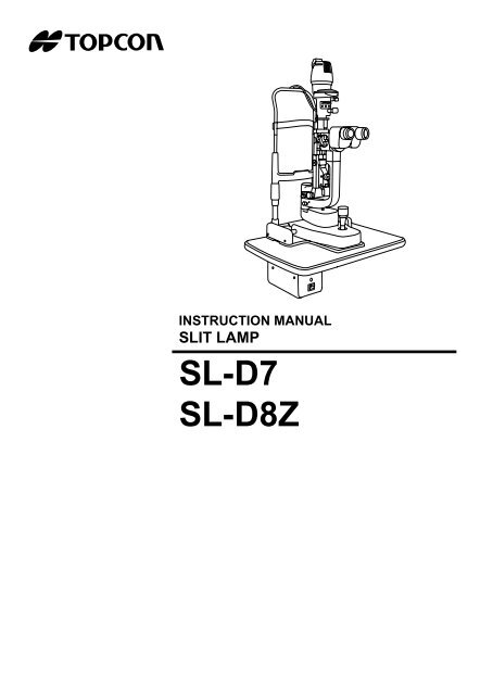
INSTRUCTION MANUAL<br />
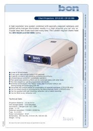
<strong>SL</strong>IT LAMP<br />
<strong>SL</strong>-<strong>D7</strong><br />
<strong>SL</strong>-<strong>D8Z</strong>
INTRODUCTION<br />
Thank you for purchasing the Slit Lamp <strong>SL</strong>-<strong>D7</strong>, <strong>SL</strong>-<strong>D8Z</strong>.<br />
This slit lamp is used for the enlargement observation of eyeballs and the parts.<br />
This instrument has the following features:<br />
• Various accessories to extend the system<br />
• Ergonomic cable layout<br />
• Clear fluorescent cornea observation and photography of cornea<br />
• Clear eyeground observation and photography by color conversion filter<br />
This Instruction Manual covers an overview of the basic operation, troubleshooting, checking,<br />
maintenance and cleaning of the Slit Lamp <strong>SL</strong>-<strong>D7</strong>, <strong>SL</strong>-<strong>D8Z</strong>.<br />
To get the best usage from the instrument, please read “Displays for Safe Use” and “Safety Cautions”.<br />
Keep this Instruction Manual with the instrument for future reference.<br />
PRECAUTIONS<br />
WORKING ENVIRONMENT<br />
Temperature:<br />
10°C-40°C<br />
Humidity:<br />
30-75% (no dewing)<br />
Atmospheric Pressure: 700hPa-1,060hPa<br />
STORAGE METHOD<br />
1. Environmental Conditions<br />
Temperature: 10°C-40°C<br />
Humidity:<br />
30-75% (no dewing)<br />
Atmospheric Pressure:700hPa-1,060hPa<br />
2. Place of Storage<br />
(1) Protected from water splashes<br />
(2) Protected from adverse effects caused by atmospheric pressure, temperature, moisture,<br />
ventilation, sunlight, dust, salt content, sulfur, etc.<br />
(3) Stable, without slopes, and protected from vibrations, shocks (including transportation),<br />
etc.<br />
(4) Free of chemicals and gases<br />
PREMISSIBLE ENVIRONMENTAL CONDITIONS FOR TRANSPORT AND STORAGE<br />
Temperature: -20°C - 50°C<br />
Humidity : 10 - 95%<br />
1
MAINTENANCE AND CHECKS<br />
1. Regularly maintain and check equipment and parts.<br />
2. When using equipment for the first time in a while, check in advance that everything is<br />
operating as it should.<br />
3. Keep the objective lens free of fingerprints and dust.<br />
4. When not is use, protect the instrument with the dust cover.<br />
5. If the objective lens is stained, clean it in accordance with the information under “Cleaning<br />
Lenses and Mirrors” in the Instruction Manual.<br />
2
DISPLAYS FOR SAFE USE<br />
In order to ensure the safe use of the product and to prevent danger to the operator and others, or<br />
damage to property, important warnings are placed on the product and inserted in the instruction<br />
manual.<br />
It is recommended for all users to take note of the meaning of the following displays and icons<br />
before reading the "Safety Cautions" and text.<br />
DISPLAYS<br />
DISPLAY<br />
WARNING<br />
MEANING<br />
Ignoring or disregarding this notice could lead<br />
to death or serious injury.<br />
CAUTION<br />
Ignoring or disregarding this display may lead<br />
to personal injury or physical damage.<br />
• Injury refers to cuts, bruises, sprains, fractures, burns, electric shocks, etc.<br />
• Physical damage refers to damage to buildings, equipment or furniture.<br />
ICONS<br />
ICONS<br />
MEANING<br />
This indicates Prohibition.<br />
Specific content is expressed with words or an icon<br />
either inserted in the icon itself or located next to the<br />
icon.<br />
This indicates Mandatory Action.<br />
Specific content is expressed with words or an icon<br />
either inserted in the icon itself or located next to the<br />
icon.<br />
This icon indicates Hazard Alerting (Warning).<br />
Specific content is expressed with words or an icon<br />
either inserted in the icon itself or located next to the<br />
icon.<br />
3
SAFETY CAUTIONS<br />
CAUTION<br />
Icons Prevention item Page<br />
To prevent falling during use and movement, secure each unit. 15<br />
To avoid injury to the eye and nose whilst moving the base unit,<br />
make sure that you have a clear view of the slit lamp and the<br />
patient's face.<br />
29<br />
For the safety of the operator and the patient, do not place fingers<br />
between moving parts.<br />
29<br />
To avoid injury to the patient’s head, incline the illumination unit<br />
holding the base unit.<br />
30<br />
To avoid causing discomfort to the patient or any damage to the<br />
patient's eye, keep the illumination at its minimum during adjustment.<br />
30<br />
To avoid electric shocks, do not attempt overhauling, rebuilding or<br />
repairs. Ask your dealer for repair.<br />
36<br />
When replacing the lamp, switch off the power supply and remove<br />
the power cable to avoid electric shocks.<br />
44<br />
Beware of high temperatures when replacing the lamp immediately<br />
after switching it off: these could cause burns.<br />
44<br />
When replacing fuses, first switch off the power supply and remove<br />
the power cable to avoid electric shocks.<br />
46<br />
Before carrying out daily care, remove the power cable (to avoid<br />
electric shocks) and wait until the lamp house has cooled (to avoid<br />
burns).<br />
Do not touch parts inside the lamp house cover during operation<br />
and immediately after switching off the power supply: this could<br />
cause burns.<br />
The base contains strong springs. Do not attempt to disassemble<br />
or burn the base, as the springs could cause injury by shooting out<br />
of it.<br />
47<br />
47<br />
48<br />
To prevent falling during use and movement, secure optional accessories.<br />
49<br />
4
CAUTION<br />
Icons Prevention item Page<br />
This instrument has been tested (with 120V/230V) and found to<br />
comply with IEC60601-1-2: 2001.<br />
This instrument radiates radio frequency energy within standard<br />
and may affect other devices in vicinity.<br />
If you have discovered that turning on/off the instrument affects<br />
other devices, we recommend you change its position, keep a<br />
proper distance from other devices, or to change the outlet.<br />
Please consult the dealer from whom you purchased the equipment<br />
for any questions.<br />
––<br />
5
MAINTENANCE<br />
USER MAINTENANCE<br />
To maintain the safety and performance of the instrument, unless done by an authorized service<br />
engineer, never attempt to do maintenance of items other than those specified here in.<br />
For details about maintenance, read the description of this manual.<br />
REPLACING THE ILLUMINATION LAMP<br />
The illumination lamp can be replaced if necessary. For specific instructions, see page 44.<br />
REPLACING THE FIXATION TARGET BULB (FOR BULB TYPE FIXATION TARGET ONLY)<br />
The fixation target bulb can be replaced if necessary, see page 45.<br />
REPLACING THE FUSE<br />
Fuses on the primary side can be replaced, if necessary. For specific instructions, see<br />
page 46.<br />
ESCAPE CLAUSE<br />
• TOPCON shall take no responsibility for damage due to fire, earthquakes, actions by a third<br />
party or other accidents, or the negligence and misuse of the user and use under unusual<br />
conditions.<br />
• TOPCON shall take no responsibility for damage derived from the inability to use this<br />
equipment, such as a loss of business profit and suspension of business.<br />
• TOPCON shall take no responsibility for damage caused by operations other than those<br />
described in this Instruction Manual.<br />
• Diagnoses made are the responsibility of qualified doctors and TOPCON shall take no<br />
responsibility for the results of such diagnoses.<br />
6
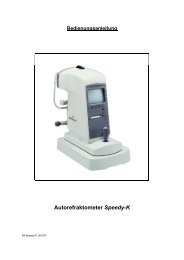
WARNING INDICATIONS AND POSITIONS<br />
To ensure safety, warning labels are provided on the instrument body.<br />
Use the instrument following these warning instructions. If any of the following labels are missing,<br />
contact your dealer or TOPCON (see the back cover).<br />
CAUTION<br />
• To prevent electric shocks, switch off the power supply and remove<br />
the power cable before replacing the lamp.<br />
Afin d’éviter tout choc électrique, coupez le contact et débranchez<br />
le câble d’alimentation avant de remplacer l’ampoule.<br />
• Do not replace the lamp immediately after switching it off: the high<br />
temperatures could cause burns.<br />
Afin d’éviter toute brûlure, prenez garde à la température élevée<br />
de l’ampoule lorsque le remplacement de celle-ci se fait immédiatement<br />
après avoir coupé l’alimentation électrique.<br />
CAUTION<br />
To avoid injury to the patient’s head,<br />
incline the illumination unit slowly<br />
while holding the base unit.<br />
Afin d’éviter toute blessure à la tête<br />
du patient, inclinez l’unité d’illumination<br />
lentement tout en maintenant la<br />
base de l’instrument.<br />
CAUTION<br />
When operating the base unit,<br />
please note the following:<br />
Pendant la manipulation de la base<br />
de l’instrument, veuillez prendre<br />
les précautions suivantes;<br />
• Beware of catching fingers in<br />
the moving parts.<br />
Prenez garde aux pièces<br />
mobiles afin d’éviter de coincer<br />
les doigts.<br />
• Avoid hitting the patient’s eyes<br />
or nose.<br />
Gardez une distance de travail<br />
appropriée afin d’éviter le contact<br />
avec les yeux et le nez du<br />
patient.<br />
CAUTION<br />
• To prevent electric shocks, turn off the power switch and remove<br />
the power cable before replacing fuses.<br />
Afin d’éviter tout choc électrique, coupez le contact et débranchez<br />
le câble d’alimentation avant de remplacer les fusibles.<br />
• Use the specified fuse.<br />
Utilisez des fusibles de même type et de même valeur.<br />
* The illustration depicts the <strong>SL</strong>-<strong>D7</strong> type.<br />
7
CONTENTS<br />
INTRODUCTION .................................................................................................1<br />
DISPLAYS FOR SAFE USE................................................................................3<br />
SAFETY CAUTIONS ...........................................................................................4<br />
MAINTENANCE...................................................................................................6<br />
USER MAINTENANCE........................................................................................6<br />
ESCAPE CLAUSE...............................................................................................6<br />
WARNING INDICATIONS AND POSITIONS ......................................................7<br />
CONFIGURATION<br />
NAMES OF MAIN BODY COMPONENTS ........................................................10<br />
STANDARD ACCESSORIES ............................................................................11<br />
COMPONENTS<br />
COMPONENTS .................................................................................................13<br />
ASSEMBLY PROCEDURE<br />
SECURING THE INSTRUMENT TYPE TABLE TOP........................................15<br />
SECURING THE UNIT TYPE TABLE TOP .......................................................16<br />
SECURING THE PATIENT GRIP PG-1(OPTIONAL ACCESSORY) ................16<br />
SECURING THE CHINREST BASE PLATE .....................................................17<br />
SECURING THE BASE UNIT AND RAIL COVER ............................................17<br />
SECURING THE BINOCULAR TUBES.............................................................18<br />
SECURING THE ILLUMINATION UNIT ............................................................18<br />
REMOVING THE ILLUMINATION UNIT PAD ...................................................19<br />
CONNECTING AND SECURING OF CABLES.................................................20<br />
FITTING THE CHINREST TISSUE ...................................................................21<br />
FITTING THE CAP ............................................................................................21<br />
SECURING THE TONOMETER MOUNT SO-TM1 (OPTIONAL ACCESSORY)21<br />
COUNTER BALANCING THE VERTICAL MOVEMENT...................................23<br />
PREPARATIONS<br />
POWERING ON ................................................................................................25<br />
ADJUSTING THE DIOPTER AND PUPILLARY DISTANCE (PD) ....................25<br />
OPERATION PROCEDURE<br />
FIXING THE PATIENT’S FACE AND FIXATION ..............................................27<br />
OPERATING THE MICROSCOPE UNIT ..........................................................28<br />
OPERATING THE BASE AND FOCUSING ......................................................29<br />
OPERATING THE ILLUMINATION UNIT..........................................................30<br />
ENDING PROCEDURE.....................................................................................35<br />
TROUBLESHOOTING<br />
TROUBLESHOOTING GUIDE ..........................................................................36<br />
8<br />
SPECIFICATIONS AND PERFORMANCE<br />
SPECIFICATIONS AND PERFORMANCE .......................................................37<br />
ELECTROMAGNETIC COMPATIBILITY ..........................................................38<br />
ELECTRIC RATING ..........................................................................................38
SYSTEM CLASSIFICATION .............................................................................39<br />
PURPOSES OF USE ........................................................................................39<br />
OPERATION PRINCIPLES ...............................................................................39<br />
SYSTEM CONFIGURATION.............................................................................40<br />
SHAPE OF PLUG..............................................................................................41<br />
SYMBOL............................................................................................................41<br />
MAINTENANCE AND CHECKUPS<br />
MAINTAINING THE PRECISION ......................................................................42<br />
PERIODIC MAINTENANCE ..............................................................................43<br />
DAILY CARE .....................................................................................................43<br />
PLACING AN ORDER FOR CONSUMABLES..................................................44<br />
REPLACING ILLUMINATION LAMPS...............................................................44<br />
REPLACEING THE FIXATION TARGET BULB................................................45<br />
REPLACING FUSES .........................................................................................46<br />
RESTOCKING CHINREST TISSUE..................................................................46<br />
DAILY CARE .....................................................................................................47<br />
CLEANING APPLIED PARTS ...........................................................................47<br />
CLEANING LENSES AND MIRRORS...............................................................47<br />
CLEANING THE <strong>SL</strong>IDING PLATE, RAIL AND WHEEL SHAFT .......................48<br />
DISPOSAL OF THE PRODUCT........................................................................48<br />
OPTIONAL ACCESSORIES<br />
DIGITAL CAMERA UNIT DC-1..........................................................................49<br />
ELECTRONIC FLASH DEVICE FD-21..............................................................50<br />
BEAM SPLITTER ..............................................................................................51<br />
TV RELAY LENS ...............................................................................................51<br />
TV RELAY LENS TL-54/55 (BUILT-IN BEAM SPLITTER TYPE) .....................52<br />
TV ATTACHMENT TL-56 ..................................................................................52<br />
TV ATTACHMENT TL-57 ..................................................................................53<br />
BACKGROUND ILLUMINATION BG-4 .............................................................53<br />
BACKGROUND ILLUMINATION BG-2GN ........................................................53<br />
PHOTO KERATOSCOPE ATTACHMENT ........................................................53<br />
OBSERVATION TUBE ......................................................................................54<br />
YELLOW FILTER UNIT .....................................................................................54<br />
12.5X MEASURING EYEPIECE........................................................................54<br />
20X EYEPIECE .................................................................................................54<br />
APPLANATION TONOMETER..........................................................................54<br />
HRUBY LENS....................................................................................................55<br />
PARALLEL BINOCULAR TUBE PB-2 ...............................................................55<br />
AUXILIARY SPRING SO-AS 1,2,3 ....................................................................55<br />
PATIENT HANDLE PG-1...................................................................................55<br />
ADAPT COVER SO-AC1, 2, 3, 4, 5...................................................................55<br />
9
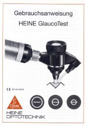
CONFIGURATION<br />
NAMES OF MAIN BODY COMPONENTS<br />
Forehead rest<br />
Chinrest<br />
Objective lens<br />
Magnification selector<br />
handle<br />
<strong>SL</strong>-<strong>D7</strong> Microscope Unit<br />
*2 Barrier filter selector lever<br />
Diopter adjusting ring<br />
12.5× eyepiece<br />
Binocular tubes<br />
Magnification index mark<br />
Chinrest adjuster<br />
Microscope arm<br />
Cap<br />
Illumination arm<br />
Illumination arm locking<br />
knob<br />
Microscope arm<br />
locking knob<br />
Power Supply<br />
Power switch<br />
Base relay cable<br />
*3 Table<br />
Illumination Unit<br />
Table<br />
Plug<br />
Lamp house cover<br />
Aperture/slit length<br />
display window<br />
*1 Exciter filter<br />
Color conversion filter<br />
selector lever<br />
Filter selector lever<br />
Aperture/slitlength<br />
control<br />
Chinrest Unit<br />
Canthus marker<br />
Mirror<br />
Centering knob<br />
Inclination lever<br />
Slit-width control knob<br />
Photo switch<br />
Control lever<br />
Base Unit<br />
Base locking knob<br />
Brightness adjustment<br />
knob<br />
Base<br />
*1,2) A model without exciter filter for slit<br />
lamp/barrier filter for slit lamp is also<br />
available.<br />
*3) A model without table unit is also<br />
available.<br />
<strong>SL</strong>-<strong>D8Z</strong> Microscope Unit<br />
Objective lens<br />
Tonometer mount<br />
Magnification index mark<br />
Magnification selector handle<br />
10<br />
CONFIGURATION
STANDARD ACCESSORIES<br />
Make sure that all the following standard accessories are included.<br />
Figures in parentheses are the quantities.<br />
Chinrest tissue (1) Dust-cover (1)<br />
Test rod (1)<br />
(This is not always included with the standard<br />
specifications.)<br />
Crosshead screwdriver (1)<br />
Spare illumination lamp (1) Screwdriver (1)<br />
Spare socket (1) Spare fuse (2)<br />
(Depending on specification, quantity may differ,<br />
or this item may not be included in stan-dard<br />
accessories.)<br />
Spare fixation target bulb (1)<br />
(for bulb type fixation target only)<br />
Spanner (1)<br />
(for instrument type table top only)<br />
11<br />
CONFIGURATION
Spare chinrest tissue pin (2) Instruction Manual (1)<br />
Cleaning brush (1) Hexagon wrench (2)Attached document (1)<br />
Square mirror (1) Accessory case (1)<br />
(This is not always included with the standard<br />
specifications.)<br />
Cap (1)<br />
For optional accessories, see “Optional Accessories” on page 49.<br />
12<br />
CONFIGURATION
COMPONENTS<br />
COMPONENTS<br />
(1) Illumination unit (2) Binocular tubes (3) Base unit<br />
* The photo shows the <strong>SL</strong>-<strong>D7</strong> type.<br />
(4) Instrument type table top<br />
(w/power supply)<br />
(4)’ Unit type table top (5) Rail cover<br />
(6) Chinrest unit (7) Power cable (8) Auxiliary spring<br />
(9) Setscrew (10) Cable cover (11) Cable cover fixing screw<br />
(12) Rail cover fixing screw (13) Cable clip (14) Tonometer maunt SO-TM1<br />
13<br />
COMPONENTS
Article name Qty Article name Qty<br />
(1) Illumination unit 1 (8) Auxiliary spring 2<br />
(2) Eyepiece unit 1 (9) Setscrew 2<br />
(3) Base unit 1 (10) Cable cover 1<br />
(4) Instrument type table top<br />
(w/power supply)*<br />
1 (11) Cable cover fixing screw 2<br />
or (4)’ Unit type table top* 1 (12) Rail cover fixing screw 4<br />
(5) Rail cover 2 (13) Cable clip 1<br />
(6) Chinrest unit* 1 (14) Tonometer maunt SO-TM1* 1<br />
(7) Power cable 1<br />
* (4) or (4)’ table top is not included, depending on the specifications.<br />
* (6) Depending on chinrest and (14) Tonometer mount might not be included.<br />
14<br />
COMPONENTS
ASSEMBLY PROCEDURE<br />
SECURING THE INSTRUMENT TYPE TABLE TOP<br />
CAUTION<br />
To prevent falling during use and movement, secure each unit.<br />
FITTING TO AUTOMATIC INSTRUMENT TABLE AIT-20/AIT-15<br />
1 Remove the cover of the instrument table. Remove the 3 screws of the cover (AIT-20<br />
only: For details, refer to the instruction manual of AIT-20.)<br />
2 Place the tabletop on the instrument table, and secure it with the 4 bolts attached to the<br />
instrument table. To reverse the direction of the instrument table, remove the power supply<br />
from the bottom of the table top and secure it on the opposite side.<br />
Connect the power cable to the table outlet and power supply of the instrument<br />
table. Place the excess cable inside the cover, and attach the cover.<br />
15<br />
ASSEMBLY PROCEDURE
SECURING THE UNIT TYPE TABLE TOP<br />
1 Remove the plastic washer from the unit type table top, which is taped to the shaft assembly.<br />
2 Insert the plastic washer, together with the shaft, into the cavity for the ophthalmic unit<br />
arm.<br />
Washer<br />
In the unit type table top, the power supply is fitted to attach the ophthalmic unit on<br />
the right hand side. When attaching the ophthalmic unit on the left-hand side,<br />
remove the power supply and reattach it to the right hand side (with 4 screws).<br />
SECURING THE PATIENT GRIP PG-1(OPTIONAL ACCESSORY)<br />
1 Align the patient grip with a groove on the rear of the chinrest base.<br />
2 Fix the patient grip with screws.<br />
Chinrest base<br />
Patient grip<br />
16<br />
ASSEMBLY PROCEDURE
SECURING THE CHINREST BASE PLATE<br />
1 Secure the chinrest base plate to the unit type table top with 2 screws (9).<br />
Chinrest base plate<br />
SECURING THE BASE UNIT AND RAIL COVER<br />
1 Align the wheel of the base unit with the rail of the chinrest base plate.<br />
2 Secure the rail covers with 4 screws (12): (2 screws each on the right and left sides).<br />
Rail cover<br />
17<br />
ASSEMBLY PROCEDURE
SECURING THE BINOCULAR TUBES<br />
1 Align the pin of the microscope unit with the groove on the binocular tubes, and fit the<br />
screw with a hexagon wrench.<br />
In the model without excitor/barrier filter, fit binocular tube with the fixing screw.<br />
Make sure you do not touch the lens surfaces.<br />
Screw<br />
Microscope unit<br />
* The illustration<br />
depicts the <strong>SL</strong>-<strong>D7</strong><br />
SECURING THE ILLUMINATION UNIT<br />
1 Loosen the microscope arm locking-knob of the base unit, manually turn the shaft and tilt<br />
the guide rod-shaft index 30-60°, then refasten the microscope-arm locking-knob.<br />
30° - 60°<br />
Indices<br />
18<br />
ASSEMBLY PROCEDURE
2 Loosen the fixing screw on the outside of the fitting cavity of the illumination unit with a<br />
screwdriver. Align indices and slowly lower the illumination unit onto the shaft of the base<br />
unit.<br />
Indices<br />
While assembling the illumination unit, take care not to get your fingers caught.<br />
3 Firmly tighten the fixing screw with a screwdriver.<br />
REMOVING THE ILLUMINATION UNIT PAD<br />
1 Remove the rubber band and slowly withdraw the protection pad from the slit operation<br />
mechanism of the illumination unit.<br />
Protection pad (for transportation)<br />
19<br />
ASSEMBLY PROCEDURE
CONNECTING AND SECURING OF CABLES<br />
1 Remove the tape from the lamp house cover of the illumination unit. Plug the cable from<br />
the upper part of the chinrest into the illumination unit.<br />
Plug<br />
2 Connect the cable from the lower part of the chinrest unit and the power cable to the<br />
power supply.<br />
Illumination cable<br />
Fixation cable<br />
Power cable<br />
3 Pass the 5 pin connector from the metal plug connected to the power supply through the<br />
hole of the chinrest and connect to the base unit.<br />
4 Fit the cable cover with 2 screws (11).<br />
5 Pull the base unit toward the side of the operator, then lock.<br />
Attach the cables to the back of the table with the cable clip (13).<br />
6 Move the base unit and illumination unit, and make sure there is enough cable to allow<br />
free movement of the base unit in all directions.<br />
20<br />
ASSEMBLY PROCEDURE
FITTING THE CHINREST TISSUE<br />
1 Remove the chinrest tissue pins.<br />
2 Take approximately one-fifth of the pad of chinrest tissues and secure this at each end<br />
with the pins.<br />
FITTING THE CAP<br />
1 Fit the cap to the shaft aligning the guide rod with the groove in the cap.<br />
SECURING THE TONOMETER MOUNT SO-TM1 (OPTIONAL ACCESSORY)<br />
Depending on specification, SO-TM1 may be included in standard accessories.<br />
1 Align the locating pin of SO-TM1 into the holes of the microscope, and fasten the screw.<br />
Screw<br />
Locating Pin<br />
The holes<br />
21<br />
ASSEMBLY PROCEDURE
2 Remove the fixing knob of the microscope, and secure the eyepieceunit, etc with the<br />
packaged screw.<br />
Fixing knob<br />
Screw<br />
3 Applanation tonometer R900 type, Photokeratoscope attachment, etc could be mounted<br />
on SO-TM1.<br />
22<br />
ASSEMBLY PROCEDURE
COUNTER BALANCING THE VERTICAL MOVEMENT<br />
When accessories, including the photography unit, are fitted to the main body, the vertical<br />
counter-balance movement may need to be adjusted. To correct this, auxiliary springs must<br />
be fitted.<br />
Major Combinations of Accessories and Necessary Auxiliary Springs<br />
Accessories<br />
TV relay lens TL-55 + SONY DXC-33 (DXC-390)<br />
TV attachment TL-56 +<br />
Nikon Microsystem (Coolpix + Adapter lens)<br />
Digital camera unit DC-1<br />
TV relay lens TL-54 + JVC KY-F70<br />
Electronic flash device FD-21 + Digital camera unit DC-1<br />
Electronic flash device FD-21 (w/TV relay lens TL-55) +<br />
SONY DXC-390<br />
Beam splitter + Observation tube<br />
Still camera attachment SR-53 + Nikon mount + Fuji S2 Pro<br />
Beam splitter + TV relay lens (1/2C) + JVC KY-F70<br />
Electronic flash device FD-21 + beam splitter + TV relay lens<br />
TL-53 + SONY DXC-390<br />
Electronic flash device FD-21 (w/TV relay lens TL-54) +<br />
JVC KY-F70<br />
Electronic flash device FD-21<br />
(w/still camera attachment SR-53) + Fuji Finepix S2 Pro<br />
Electronic flash device FD-21 + beam splitter +<br />
TV relay lens (1/2C) + JVC KY-F70<br />
Electronic flash device FD-21<br />
(w/still camera attachment SR-52) + Nikon D1 (X)<br />
Each auxiliary spring consists of 2 identical springs.<br />
Do not use different springs in a set.<br />
Auxiliary Spring type<br />
Tonometer<br />
is not fitted<br />
–––<br />
Standard<br />
auxiliary<br />
spring<br />
Auxiliary<br />
spring<br />
SO-AS1<br />
Auxiliary<br />
spring<br />
SO-AS2<br />
Tonometer<br />
is fitted<br />
Standard<br />
auxiliary<br />
spring<br />
Standard<br />
auxiliary<br />
spring<br />
Auxiliary<br />
spring<br />
SO-AS1<br />
Auxiliary<br />
spring<br />
SO-AS2<br />
Auxiliary<br />
spring<br />
SO-AS3<br />
Auxiliary<br />
spring<br />
SO-AS3<br />
23<br />
ASSEMBLY PROCEDURE
COUNTER-BALANCE PROCEDURE<br />
1 Turn the control lever clockwise and raise the base to the top position, remove the center<br />
screw and take off the cover.<br />
Cover<br />
2 Insert the auxiliary spring unit vertically into the auxiliary spring port, with the flange face<br />
turned upwards. (Make sure that the spring is inserted into the groove in the bottom of the<br />
port.)<br />
Auxiliary spring port<br />
3 Open the auxiliary spring unit with the auxiliary spring port, and lightly push the spring till it<br />
stops. (A large screwdriver, a flat sheet metal tool, a coin, etc. can be used to this end.)<br />
4 With the auxiliary spring unit lightly touching the stopper, turn about 90° (in either direction),<br />
then release. The auxiliary spring locks into the positioning groove and assembly is<br />
complete. (To remove the auxiliary spring, lightly press it down to the stopper, rotate it 90°<br />
and remove from the port.)<br />
24<br />
ASSEMBLY PROCEDURE
PREPARATIONS<br />
POWERING ON<br />
1 Connect the power cable.<br />
2 Turn ON the POWER switch.<br />
ADJUSTING THE DIOPTER AND PUPILLARY DISTANCE (PD)<br />
NOTICE<br />
To ensure sharp observation of slit images, always carry out the<br />
diopter and PD adjustments.<br />
In case that no test rod is provided, set the diopter scale to your diopter by turning the diopter<br />
adjustment ring.<br />
1 Insert the test rod into the rotation shaft cavity, and set the black face square with the<br />
microscope.<br />
Test rod<br />
* The illustration<br />
depicts the <strong>SL</strong>-<strong>D7</strong><br />
2 Set the eyepiece with scale to the non-dominant eye side.<br />
3 Turn ON the POWER switch, and place the brightness adjustment knob in an intermediate<br />
position.<br />
4 Adjust the illumination φto 10mm by adjusting the slit adjustment knob and aperture/slitlength<br />
selector knob.<br />
5 Turn the diopter adjusting ring of the eyepiece with scale ( ) fully counter-clockwise.<br />
6 Turn the diopter adjusting ring clockwise and stop when both the scale ( ) and test rod<br />
can be clearly seen.<br />
7 Read the value on the diopter scale of the stop position. The value shows the diopter (D).<br />
8 Set the diopter scale of the other eyepiece to the read value.<br />
9 Set the eyepiece with scale ( ) to the dominant eye side, and adjust the diopter scale of<br />
the dominant eye as in steps 5 and 6.<br />
10 After adjusting the diopter, turn the slit adjustment knob until the slit width is about 1mm,<br />
then check if the slit image projected on the test rod can be clearly seen with both right<br />
and left eyes.<br />
25<br />
PREPARATIONS
11 Holding the prism box, look through the eyepiece with both eyes, and adjust the pupillary<br />
distance so that the image projected on the test rod can be seen without diplopia (double<br />
vision), and appears to be three dimensional.<br />
Diopter adjusting ring<br />
Prism box<br />
Diopter scale<br />
* The illustration depicts<br />
the <strong>SL</strong>-<strong>D7</strong> type.<br />
26<br />
PREPARATIONS
OPERATION PROCEDURE<br />
FIXING THE PATIENT’S FACE AND FIXATION<br />
The model without a fixation target is also available.<br />
1 Place the patient's chin on the chinrest with his forehead against the forehead rest.<br />
2 By rotating the chinrest adjuster, align the patient's eye with the canthus marker on the<br />
chinrest frame.<br />
Forehead rest<br />
Canthus marker<br />
Chinrest<br />
Chinrest adjuster<br />
3 Ask the patient to look at the fixation target with the eye that is not being examined.<br />
To change the patient's fixation point, hold the fixation target at the end opposite to the<br />
target and adjust accordingly.<br />
tar-<br />
Fixation<br />
get lever<br />
(A) Fixation target with<br />
diopter adjustment<br />
Fixation target unit<br />
Diopter adjusting<br />
ring<br />
(B) Luminous fixation target<br />
When using the fixation target with diopter adjustment (A), slide the diopter adjustment<br />
knob so that the patient can see the following target ( ). The ring target can<br />
be adjusted within a range of -15D to +10D.<br />
The luminous fixation target is used for myopia of -15D or more.<br />
When replacing targets, remove the target by pulling<br />
gently whilst supporting the opposite end.<br />
27<br />
OPERATION PROCEDURE
OPERATING THE MICROSCOPE UNIT<br />
<strong>SL</strong>-<strong>D7</strong><br />
Turn the magnification selector to set a magnification value against the magnification index<br />
mark.<br />
Magnification selector<br />
handle<br />
Magnification index mark<br />
<strong>SL</strong>-<strong>D8Z</strong><br />
Magnification index mark<br />
Magnification selector handle<br />
For the overall magnification in conjunction with magnification marks of the magnification<br />
selector handle, see page 37.<br />
28<br />
OPERATION PROCEDURE
OPERATING THE BASE AND FOCUSING<br />
CAUTION<br />
To avoid injury to the eye and nose whilst moving the base<br />
unit, make sure that you have a clear view of the slit lamp and<br />
the patient's face.<br />
CAUTION<br />
For the safety of the operator and the patient, do not<br />
place fingers between moving parts.<br />
NOTICE<br />
To prevent dropping the base locking knob from the base, do<br />
not loosen the knob too much.<br />
1 For major horizontal movements, hold the control lever in the upright position and move<br />
the entire base.<br />
2 For fine adjustments, move the control lever in the required direction.<br />
3 The base can be raised by turning the control lever clockwise, and lowered by turning the<br />
control lever counter-clockwise.<br />
4 To fix the base, fasten the base locking knob.<br />
Control lever<br />
Base locking knob<br />
Base<br />
• Rough focusing is carried out with major movements, following step 1-3.<br />
• Fine focusing is done with the microscope, following steps 2 and 3.<br />
29<br />
OPERATION PROCEDURE
OPERATING THE ILLUMINATION UNIT<br />
CAUTION<br />
To avoid injury to the patient’s head, incline the illumination<br />
unit holding the base unit.<br />
CAUTION<br />
NOTICE<br />
To avoid causing discomfort to the patient or damage to the<br />
patient's eye, keep the illumination at its minimum during<br />
adjustment.<br />
• Adjust the slit width according to the results of the investigation.<br />
• The slit-width scale should be used as a guideline.<br />
• When using the square mirror, incline the illumination unit at<br />
least 10º.<br />
• To protect the patient, use the heat absorption filter, as<br />
required.<br />
ADJUSTING THE BRIGHTNESS<br />
Turn the brightness adjustment knob.<br />
The brightness of the illumination light can be adjusted to the preferred illumination setting.<br />
Brightness adjustment<br />
knob<br />
ADJUSTING THE <strong>SL</strong>IT WIDTH<br />
Turn the slit-width control knob.<br />
The slit width can be changed gradually between 0 and 14mm (14mm=circle).<br />
Slit-width control knob<br />
30<br />
OPERATION PROCEDURE
CHANGING THE APERTURE/<strong>SL</strong>IT LENGTH<br />
Turn the aperture/slit-length control knob.<br />
When the slit is fully opened, 6 types of spot illumination (φ14, φ10, φ5, φ2, φ1, φ0.2) are available.<br />
The slit width can be changed gradually from 1mm to 14mm.<br />
The spot illumination size and slit length are displayed on the aperture/slit-length<br />
display window.<br />
This function is used for scanning observation and observation with indirect illumination.<br />
Aperture/slitlength<br />
display win-<br />
Aperture/slitlength<br />
control<br />
TURNING THE <strong>SL</strong>IT<br />
Horizontally rotate the aperture/slit-length control knob.<br />
This directly changes the slit image from vertical to horizontal. In this mode, the slit angle can<br />
be read off the angle scale.<br />
Aperture/slitlength<br />
control<br />
Slit-angle scale<br />
SWINGING THE <strong>SL</strong>IT SIDEWAYS<br />
Loosen the centering knob and swing the illumination unit right and left.<br />
This provides indirect illumination displacing the slit light from the microscope center.<br />
By fastening the centering knob, the slit light returns to the center of the vision field.<br />
31<br />
OPERATION PROCEDURE
Centering knob<br />
INCLINED ILLUMINATION<br />
Press to unlock the inclination lever and pull.<br />
The illumination unit is inclined for inclined illumination up to 20° in 5° steps.<br />
This function is used for observing a horizontal cross section, and for corner angle<br />
and fundus observation.<br />
Inclination lever<br />
REFLECTION MIRROR<br />
For this instrument, a battledore mirror and a square mirror are available. For normal observation,<br />
the battledore mirror is used.<br />
However, if the arm angle scale, which represents the angle formed by the illumination arm<br />
and micro-scope arm, reads approx. 3° to 10° and the observation light flux is disturbed by the<br />
battledore mirror, then the square mirror should be used.<br />
The square mirror is to be used when the arm angle is opened to more than 10°.<br />
Battledore mirror<br />
Square mirror<br />
The square mirror is standard accessory.<br />
32<br />
OPERATION PROCEDURE
REPLACING REFLECTION MIRRORS<br />
Replace mirrors as follows, taking care not to touch the mirror and lens surfaces:<br />
• Open the microscope arm and illumination arm 30° or more.<br />
• Incline the illumination unit 10° or more.<br />
• Pull out the battledore mirror, holding the slender part on both sides. To reinsert the battledore<br />
mirror, hold the slender part on both sides and insert.<br />
• Insert the square mirror from the side recessed on the back.<br />
• To pull out the square mirror, which has no handle, push it up with a pencil, or something<br />
similar, as illustrated below.<br />
Battledore mirror<br />
Square mirror<br />
If you touch the mirror or lens surface, please clean this according to the process<br />
on page 47 "Cleaning Lenses and Mirrors".<br />
CHANGING FILTERS<br />
Move the filter selector lever right and left to select the required filter from the 5 types.<br />
Green-colored<br />
Heat-absorption Red-free filter<br />
filter<br />
No filter ND filter Blue filter or no filter ( )<br />
Aperture/slit length<br />
display window<br />
Filter selector lever<br />
Aperture/slit length<br />
control knob<br />
33<br />
OPERATION PROCEDURE
AMBER FILTER<br />
The amber filter is used to facilitate fundus observation.<br />
The filter is inserted or removed by the amber filter selector lever.<br />
ON<br />
OFF<br />
Amber filter selector<br />
lever<br />
FLUORESCENCE OBSERVATION<br />
(EXCITER FILTER FOR <strong>SL</strong>IT LAMP/BARRIER FILTER FOR <strong>SL</strong>IT LAMP)<br />
Fluorescence observation can be carried out using the exciter filter for slit lamp and barrier filter<br />
for slit lamp.<br />
1 Turn the aperture/slit-length display window anti-clockwise until the blue circle appears,<br />
then insert the exciter filter for slit lamp into the illumination path.<br />
Aperture/slit-length<br />
display window<br />
Aperture/slit-length<br />
control knob<br />
2 Turn the barrier filter selector lever to the right and insert the barrier filter for slit lamp.<br />
Barrier filter selector lever<br />
* The illustration depicts<br />
the <strong>SL</strong>-<strong>D7</strong> type.<br />
34<br />
OPERATION PROCEDURE
DIFFUSION LENS<br />
When in use, the diffusion lens is set vertically in front of the reflection mirror.<br />
When not in use, remove the lens from the light path.<br />
The diffusion lens is used for observing the entire object with a low magnifica-tion.<br />
NOTICE<br />
When using the diffusion lens, open the microscope arm and<br />
illumination arm 30° to avoid friction of the diffusion lens and<br />
illumination support. Also, fully open the slit; otherwise this<br />
prevents sufficient light from entering.<br />
Diffusion lens<br />
* The illustration depicts<br />
the <strong>SL</strong>-<strong>D7</strong> type.<br />
ENDING PROCEDURE<br />
Turn OFF the Power switch.<br />
35<br />
OPERATION PROCEDURE
TROUBLESHOOTING<br />
TROUBLESHOOTING GUIDE<br />
CAUTION<br />
To avoid electric shocks, do not attempt overhauling, rebuilding<br />
or repairs. Ask your dealer for repair.<br />
If you suspect a problem, check the possible cause by means of the check list below.<br />
If the check list below does not solve the problem, or if the problem is not included in the list,<br />
contact your dealer or TOPCON (see the back cover).<br />
Check List<br />
Problem Possible cause Check Page<br />
Illumination lamp<br />
does not work<br />
Illumination field is<br />
not uniform/is<br />
shady/is dark<br />
Fixation target lamp<br />
does not work<br />
Fuse blows<br />
Slit width narrows by<br />
itself<br />
Cable connection is<br />
disconnected<br />
Check cable connection. 20<br />
Base relay cable is switched<br />
off.<br />
Connect the cable. 20<br />
Plug of lamp house cover is<br />
switched off<br />
Insert plug. 20<br />
POWER switch is OFF Turn ON POWER switch. 25<br />
Brightness adjustment knob is<br />
the minimum<br />
Turn up brightness adjustment<br />
knob.<br />
Illumination lamp is broken<br />
Replace it with a new<br />
illumination lamp.<br />
44<br />
Socket has deteriorated Replace it with a new socket. 45<br />
Filter selector lever is out of<br />
position<br />
30<br />
Click filter selector lever. 33<br />
Fixation cable is off Insert cable. 20<br />
Rated capacity of fuse is<br />
incorrect<br />
Slit-adjustment knob torque<br />
has been decreased<br />
Use fuse with correct rating &<br />
authorized fuse.<br />
Readjust slit-width control knob<br />
torque.<br />
44, 46<br />
42<br />
36<br />
TROUBLESHOOTING
SPECIFICATIONS AND PERFORMANCE<br />
SPECIFICATIONS AND PERFORMANCE<br />
<strong>SL</strong>-<strong>D7</strong><br />
<strong>SL</strong>-<strong>D8Z</strong><br />
Microscope unit<br />
Type<br />
Galileo type<br />
Magnification Drum, 5-step magnification Manual zooming<br />
Magnification steps 6/10/16/25/40 10, 16 and 25 w/clicks<br />
Overall magnification<br />
(actual vision field)<br />
Eyepiece lens<br />
Binocular tubes<br />
Illumination unit<br />
Illumination field<br />
Slit direction<br />
Filter<br />
Illumination lamp<br />
Chinrest/forehead rest unit<br />
Forward-backward movement<br />
Right-left movement<br />
Vertical movement<br />
Amount of movement in<br />
all directions<br />
Amount of vertical movement<br />
of chinrest<br />
Fixation target* 3<br />
Fixation lamp<br />
6.37 (φ35.1mm)/<br />
9.94 (φ22.5mm)/<br />
15.87 (φ14.1mm)/<br />
25.37 (φ8.8mm)/<br />
39.62 (φ5.6mm)/<br />
Magnification: 12.5x<br />
Diopter adjustment range: -5D - +5D<br />
PD adjustment: 55 - 78mm<br />
6.35 - 31.75 (φ35.2 - φ7mm)<br />
Slit width: 0-14mm, can be altered gradually(14mm=circle)<br />
Slit length: 14-1mm, can be altered gradually(14mm=circle)<br />
Aperture diameter: φ14, 10, 5, 2, 1, 0.2<br />
Vertical to horizontal, can be altered gradually<br />
Inclination: 5/10/15/20<br />
Side swing<br />
Blue filter, red-free filter, amber filter,<br />
UV cut filter (normal use), IR cut filter (normal use),<br />
ND filter (13% transmission), heat insulation filter, exciter filter for<br />
slit lamp* 1 , barrier filter for slit lamp* 2<br />
12V, 30W halogen lamp<br />
90mm<br />
100mm<br />
30mm<br />
15mm<br />
80mm<br />
Fixation target with diopter adjustment<br />
Luminous fixation target<br />
LED (Red) or bulb (white)<br />
37<br />
SPECIFICATIONS AND PERFORMANCE
<strong>SL</strong>-<strong>D7</strong><br />
Dimensions, Weight<br />
Dimensions:<br />
w/Table<br />
550mm(W)x399mm(D)x760-790mm(H)<br />
w/ Unit Table 440mm(W)x399mm(D)x760-790mm(H)<br />
w/o Table<br />
329mm(W)x349mm(D)x652-682mm(H)<br />
w/o Table and Chinrest 329mm(W)x306mm(D)x652-682mm(H)<br />
Weight: w/Table 19kg 19.5kg<br />
w/ Unit Table 18kg 18.5kg<br />
w/o Table 13kg 13.5kg<br />
w/o Table and Chinrest 11.5kg 12kg<br />
Table size<br />
550mm x 370mm<br />
Unit Table size<br />
440mm x 350mm<br />
Height from the top to<br />
patient’s eye<br />
375mm<br />
*1), *2) A model without exciter filter for slit lamp/barrier filter for slit lamp is also available.<br />
*3) A model without fixation target is also available.<br />
• The specification and design of the product can be altered for improvements without prior<br />
notice.<br />
ELECTROMAGNETIC COMPATIBILITY<br />
• This product conforms to the EMC standard (IEC60601-1-2:2001).<br />
ELECTRIC RATING<br />
• Source voltage:100-120V, 220-240V AC, 50/60Hz<br />
• Power input: 160VA<br />
<strong>SL</strong>-<strong>D8Z</strong><br />
38<br />
SPECIFICATIONS AND PERFORMANCE
SYSTEM CLASSIFICATION<br />
• Type of protection against electric shocks: Class Ι equipment<br />
Class Ι equipment does not depend on basic insulation only for protection against electric<br />
shocks. It can also be earthed; therefore, the metal parts with which one comes into contact<br />
do not become conductive if the basic insulation fails.<br />
• Degree of protection against electric shocks: Type B applied part<br />
Type B applied part is the applied part complying with the specified requirements of the<br />
Standard IEC 60601-1 to provide protection against electric shock, particularly regarding<br />
allowable LEAKAGE CURRENT.<br />
• Degree of protection against harmful ingress of water: IPx0<br />
<strong>SL</strong>-<strong>D7</strong>/<strong>D8Z</strong> has no protection against ingress of water. (The degree of protection against<br />
harmful ingress of water defined in IEC 60529 is IPx0)<br />
• Classification according to the methods of sterilization or disinfection recommended by the<br />
manufacture: not applicable.<br />
<strong>SL</strong>-<strong>D7</strong>/<strong>D8Z</strong> has no part to be sterilized or be disinfected.<br />
• Methods of sterilization or disinfection recommended by the manufacturer: <strong>SL</strong>-<strong>D7</strong>and <strong>SL</strong>-<br />
<strong>D8Z</strong> do not have any part to be sterilized or disinfected.<br />
• Not AP or APG equipment<br />
• Classification according to the degree of safety of application in the presence of a flammable<br />
anaesthetic mixture with air or with oxygen or nitrous oxide: Equipment not suitable for use<br />
in the presence of a flammable anaesthetic mixture with air or with oxygen or nitrous oxide.<br />
<strong>SL</strong>-<strong>D7</strong>/<strong>D8Z</strong> should be used in environments where no flammable anesthetics and/or flammable<br />
gases are presents.<br />
• Classification according to the mode of operation: Continuous operation.<br />
Continuos operation is the operation under normal load for an unlimited period, without<br />
the specified limits of temperature being exceeded.<br />
PURPOSES OF USE<br />
• This instrument is used for the enlargement observation of eyeballs and the parts.<br />
OPERATION PRINCIPLES<br />
• Illuminates the observed part by the illumination light emitted from the illumination optical<br />
system and allows enlargement observation by binocular stereoscopic microscope.<br />
39<br />
SPECIFICATIONS AND PERFORMANCE
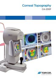
SYSTEM CONFIGURATION<br />
<strong>SL</strong>-<strong>D7</strong>/<strong>D8Z</strong> System Chart<br />
Applanation<br />
Tonometer<br />
Model R900<br />
Photo Keratoscope<br />
Attachment<br />
TOPCON product<br />
Products of other<br />
Applanation<br />
Tonometer<br />
Model T900<br />
Observation<br />
Tube<br />
Monitor TV<br />
Still Video<br />
Recorder<br />
Printer<br />
Tonometer Mount SO-TM1 (<strong>SL</strong>-<strong>D7</strong>)<br />
TV<br />
Relay Lens<br />
Video<br />
Camera<br />
Tonometer Guide Plate<br />
for T900<br />
Beam<br />
Splitter<br />
Yellow Filter<br />
TV Relay Lens<br />
TL-54 (1/2C)<br />
JVC<br />
KY-F70<br />
BGI for Halogen<br />
BG-4<br />
TV Relay Lens<br />
TL-55 (1/3C)<br />
SONY<br />
DXC-390/-C33<br />
Panasonic<br />
GP-KS162<br />
Hruby<br />
Lens<br />
BGI<br />
BG-2GN<br />
20X<br />
Eyepiece<br />
12.5X<br />
Measuring<br />
Eyepiece<br />
TV ATT<br />
TL-57<br />
TV ATT<br />
TL-56<br />
Still Camera ATT<br />
SR-52<br />
(Adapter Lens)<br />
1/2C Video<br />
Camera<br />
Nikon<br />
Coolpix<br />
Digital Imaging<br />
Processing System<br />
IMAGEnet 2000<br />
Mount Adapter<br />
Nikon<br />
D1X<br />
Xe<br />
Relay<br />
Lens<br />
(FD-21)<br />
Parallel<br />
binoculer Tubes<br />
PB-2<br />
Still Camera ATT<br />
SR-53<br />
BGI For Xe BG-3<br />
(FD-21)<br />
Adapt Cover<br />
SO-AC 1,2,3,4,5<br />
Digital Camera<br />
Unit DC-1<br />
Mount Adapter<br />
Fuji Finepix<br />
S2 Pro<br />
Flash Power Supply<br />
(FD-21)<br />
AUXILIARY SPRING<br />
SO-AS1, 2, 3<br />
PATIENT HANDLE PG-1<br />
40<br />
SPECIFICATIONS AND PERFORMANCE
SHAPE OF PLUG<br />
SYMBOL<br />
Country Voltage/frequency Shape of plug<br />
Mexico 110V/50Hz Type C&E<br />
Argentina 220V/60Hz Type A<br />
Peru 220V/60Hz Type A<br />
Venezuela 110V/50Hz Type C&E<br />
Bolivia & Paraguay<br />
220V/60Hz<br />
Type A (Most common)<br />
Type H (Infrequently)<br />
Chile 220V/60Hz Type A<br />
Colombia 110V/50Hz Type C<br />
Brazil<br />
220V/60Hz<br />
127V/60Hz<br />
Type A<br />
Type C<br />
Ecuador 110V/50Hz Type C&E<br />
Symbol IEC Publication Description Description (French)<br />
60417-5032 Alternation Current Courant alternatif<br />
60348<br />
60417-5008<br />
60417-5007<br />
Attention, consult accompanying<br />
documents<br />
Off (power: disconnection<br />
from the mains)<br />
On (power: connection of<br />
the mains)<br />
Attention, consulter les documents<br />
d’accompagnement<br />
Éteint (courant: coupure<br />
avec le secteur)<br />
Allumé (courant: raccordement<br />
sur le secteur)<br />
60878-02-02 Type B applied part Classe B<br />
41<br />
SPECIFICATIONS AND PERFORMANCE
MAINTENANCE AND CHECKUPS<br />
MAINTAINING THE PRECISION<br />
ADJUSTING THE <strong>SL</strong>IT WIDTH CONTROL KNOB TORQUE<br />
• If the slit width narrows by itself due to a decrease in slit width control knob torque, adjust the<br />
torque as follows.<br />
1 Using the attached hexagon wrench, loosen the slit width control knob.<br />
2 Press the slit-width control knob on the left-hand side, and turn the right-hand side clockwise.<br />
3 Fasten the slit width control knob on the right-hand side with the hexagon wrench.<br />
ADJUSTING THE INCLINATION TORQUE<br />
• If the inclination torque of the illumination unit is too low, fasten the arm inclination by tightening<br />
the screws clockwise on both sides of the arm.<br />
* The illustration depicts<br />
the <strong>SL</strong>-<strong>D7</strong> type.<br />
42<br />
MAINTENANCE AND CHECKUPS
PERIODIC MAINTENANCE<br />
Before using, confirm the following:<br />
• Adjust the diopter and eye width following “ADJUSTING THE DIOPTER AND PUPILLARY<br />
DISTANCE (PD)” on page 25 and turn the slit adjustment knob and make the slit width<br />
about 1mm: The slit image projected on the test rod is seen clearly.<br />
• Move the base forward-backward and right-left: The base moves smoothly.<br />
• Component parts, including the eyepiece unit, are fitted in place.<br />
• The chinrest base is firmly fitted to the table.<br />
• Cables and plugs are firmly connected.<br />
DAILY CARE<br />
• This instrument may be affected adversely by dust. Apply the dust cover when not using.<br />
43<br />
MAINTENANCE AND CHECKUPS
PLACING AN ORDER FOR CONSUMABLES<br />
• When ordering consumable items, contact your dealer or TOPCON (see the back cover).<br />
Specify the article name, product code and quantity.<br />
Article name<br />
Product code<br />
Illumination lamp 446802570<br />
Socket 446802590<br />
Chinrest tissue 403104082<br />
Fuse T-1A, 250V (Bel Fuse, Part No.5TT1):100-120V 446356003<br />
Fuse T-0.75A, 250V (Bel Fuse, Part No.5TT750):220-240V 447706351<br />
Fixation target bulb 403504211<br />
REPLACING ILLUMINATION LAMPS<br />
CAUTION<br />
When replacing the lamp, switch off the power supply and<br />
remove the power cable to avoid electric shocks.<br />
CAUTION<br />
Beware of high temperatures when replacing the lamp immediately<br />
after switching it off: these could cause burns.<br />
NOTICE<br />
• To ensure perfect illumination, make sure that the socket<br />
flange and notch are firmly fitted to the lamp house.<br />
• Use a soft cloth and do not touch the illumination lamp with<br />
bare fingers: fingerprints and stains may affect illumination<br />
and cause premature failure of the lamp.<br />
1 Turn OFF the POWER switch and remove the cable plug.<br />
2 Turn the lamp housing cover clockwise and remove upward.<br />
3 Lightly pull the socket fixing lever and turn in the direction indicated by the arrow.<br />
Socket fixing lever<br />
Lamp<br />
4 Remove the socket assembly with the lamp.<br />
5 Remove the lamp from the socket.<br />
6 Fit the new lamp in reverse order, making sure the direction of the illumination lamp and<br />
socket is correct.<br />
44<br />
MAINTENANCE AND CHECKUPS
REPLACING SOCKETS<br />
NOTICE<br />
The socket may deteriorate due to the constant heat: therefore,<br />
it should be replaced after the lamps have been changed<br />
two or three times.<br />
1 Remove the lamp following steps 1-4 of “Replacing Illumination Lamps”.<br />
2 Loosen the cable-fixing terminal, remove the cable, and replace the socket with a new<br />
one.<br />
3 Fit the new socket in reverse order.<br />
Cable-fixing terminal<br />
REPLACEING THE FIXATION TARGET BULB<br />
1 Turn OFF the POWER switch.<br />
2 Loosen the locking screw and the remove the fixation target. (Do not over-loosen the<br />
locking screw, or it may drop.)<br />
3 Hold the top of bulb and pull it out; then insert the new bulb.<br />
4 Insert the fixation target, then tighten the locking screw.<br />
Locking screw<br />
Fixation<br />
target bulb<br />
45<br />
MAINTENANCE AND CHECKUPS
REPLACING FUSES<br />
CAUTION<br />
When replacing fuses, first switch off the power supply and<br />
remove the power cable to avoid electric shocks.<br />
NOTICE<br />
Use the glass tube fuse with the rating as stated on the side of<br />
the fuse holder.<br />
1 Switch OFF the POWER switch and remove the power cable from the AC power source.<br />
2 Turn the fuse carrier with a straight-bladed screwdriver. Remove the fuse from its carrier.<br />
3 Replace it with a new fuse of the correct rating.<br />
4 Fit the fuse carrier in reverse order.<br />
Fuse holder<br />
RESTOCKING CHINREST TISSUE<br />
When the chinrest tissue supply is depleted, pull out the chinrest tissue pins and replace tissue.<br />
46<br />
MAINTENANCE AND CHECKUPS
DAILY CARE<br />
CAUTION<br />
CAUTION<br />
NOTICE<br />
Before carrying out daily care, remove the power cable (to<br />
avoid electric shocks) and wait until the lamp house has cooled<br />
(to avoid burns).<br />
Do not touch parts inside the lamp house cover during operation<br />
and immediately after switching off the power supply: this<br />
could cause burns.<br />
• To prevent the chinrest, forehead rest and other plastic<br />
parts from discoloration and deterioration, do not use volatile<br />
solvents for cleaning, including benzine, thinner, ether,<br />
gasoline, etc.<br />
• Wipe parts with a cloth moistened with a tepid solution of<br />
neutral kitchen detergent.<br />
CLEANING APPLIED PARTS<br />
Wipe the forehead rest, the chinrest and the patient grip (if a pair of patient grip is used) with a<br />
cloth moistened with a tepid solution of neutral detergent for kitchenware.<br />
CLEANING LENSES AND MIRRORS<br />
REMOVING STAINS<br />
NOTICE<br />
To prevent damaging lens surfaces, do not hold gauze with<br />
tweezers.<br />
1 Prepare a solution of ethyl alcohol 20% and ether 80%.<br />
2 Remove dust from lens and mirror surfaces with the cleaning brush, or a blower.<br />
3 Using clean gauze or lint-free tissue, lightly clean with a rotating movement from the<br />
center of the lens/mirror outwards.<br />
4 If the stain remains, repeat this 2 to 3 times.<br />
5 If stains are persistent, call your dealer or TOPCON (see the back cover).<br />
47<br />
MAINTENANCE AND CHECKUPS
CLEANING THE <strong>SL</strong>IDING PLATE, RAIL AND WHEEL SHAFT<br />
NOTICE<br />
When stained, the movement of the sliding plate and rail of the<br />
tabletop and the wheel shaft of the base becomes less<br />
smooth. Clean them with a dry cloth.<br />
1 Move the base right and left and wipe the wheel shaft clean with a dry cloth.<br />
2 Hold up the control lever and clean the sliding plate with a dry cloth.<br />
Rail<br />
Wheel shaft<br />
Control lever<br />
Sliding plate<br />
DISPOSAL OF THE PRODUCT<br />
CAUTION<br />
The base contains strong springs. Do not attempt to disassemble<br />
or burn the base, as the springs could cause injury by<br />
shooting out of it.<br />
• For disposal of the instrument and consumables, contact a waste disposer or call your<br />
dealer or TOPCON (see the back cover).<br />
48<br />
MAINTENANCE AND CHECKUPS
OPTIONAL ACCESSORIES<br />
TOPCON Slit Lamp <strong>SL</strong>-<strong>D7</strong> provides the following optional accessories for imaging.<br />
For inquiries, please call your dealer or TOPCON (see the back cover).<br />
CAUTION<br />
To prevent falling during use and movement, secure optional<br />
accessories.<br />
• For details, please refer to the instruction manuals of each product.<br />
DIGITAL CAMERA UNIT DC-1<br />
FEATURES<br />
• A digital camera is incorporated with the slit lamp<br />
• As wiring is housed in the arm, cables do not disturb operations.<br />
• Recording with Compact flash card<br />
• Can be connected to the IMAGEnet.<br />
49<br />
OPTIONAL ACCESSORIES
ELECTRONIC FLASH DEVICE FD-21<br />
FEATURE<br />
Can be connected to a marketed camera for flash photography.<br />
CAMERAS TO BE USED<br />
Cameras that can be connected to <strong>SL</strong>-<strong>D7</strong> are shown below. The necessary camera attach--<br />
ment and connection cable differ depending on the camera to be used.<br />
Recommended camera<br />
Nikon D1 series<br />
Fuji finepix S-Pro series<br />
JVC KY-F70<br />
SONY DXC-390<br />
TOPCON DC-1<br />
Camera attachment<br />
Camera attachment SR-52<br />
Camera attachment SR-53<br />
TV relay lens TL-54<br />
TV relay lens TL-55<br />
Built-in type photography unit<br />
50<br />
OPTIONAL ACCESSORIES
BEAM SPLITTER<br />
FEATURES<br />
• Used to attach the TV relay lens T-53 (w/ beam splitter type) and observation tube<br />
• The TV relay lens T-53 and observation tube can be attached to either side.<br />
• The beam splitter division ratio is TV 50%: patient 50%.<br />
TV RELAY LENS<br />
• Four types of TV relay lens are prepared for different TV camera types to be used (C mount<br />
2/3 type, C mount 1/2 type, C mount 1/3 type and bayonet mount 1/2 type for Sony).<br />
FEATURES<br />
• Used with the beam splitter.<br />
• Can connect a TV camera to carry out monitor observation and photograph still images.<br />
51<br />
OPTIONAL ACCESSORIES
TV RELAY LENS TL-54/55 (BUILT-IN BEAM SPLITTER TYPE)<br />
• The type of TV relay lens differs according to the type of TV camera to be used.<br />
TV relay lens for 1/2 type TV camera: TL-54<br />
TV relay lens for 1/3 type TV camera: TL-55<br />
FEATURES<br />
• Incorporated with the beam splitter.<br />
• Can connect a TV camera to carry out monitor observation and photograph still images.<br />
• The beam splitter can be switched IN/OUT.<br />
• The beam splitter division ratio is TV 50%: patient 50%.<br />
TV ATTACHMENT TL-56<br />
FEATURES<br />
• Used to connect the Nikon Coolpix series digital camera.<br />
• Incorporated with the beam splitter.<br />
• The beam splitter division ratio is TV 50%: patient 50%.<br />
52<br />
OPTIONAL ACCESSORIES
TV ATTACHMENT TL-57<br />
FEATURES<br />
• Used to connect the Panasonic GP-KS162 digital camera.<br />
• Incorporated with the beam splitter.<br />
• The beam splitter division ratio is TV 50%: patient 50%.<br />
BACKGROUND ILLUMINATION BG-4<br />
FEATURES<br />
• Used for background illumination.<br />
• The light volume differs according to the illumination light volume of the<br />
slit lamp.<br />
• Equipped with 3-step illumination function (fully open, half open,<br />
closed).<br />
BACKGROUND ILLUMINATION BG-2GN<br />
FEATURES<br />
• Used for background illumination with LED light source.<br />
• Power is supplied from the slit lamp power supply.<br />
• Light intensity can be adjusted.<br />
<br />
PHOTO KERATOSCOPE ATTACHMENT<br />
FEATURES<br />
• Can easily record the cornea configuration by camera.<br />
* For attachment to <strong>SL</strong>-<strong>D7</strong>, the tonometer mount SO-TM1 is<br />
required.<br />
* For photography, FD-21 and a photography unit/TV relay<br />
lens are required.<br />
53<br />
OPTIONAL ACCESSORIES
OBSERVATION TUBE<br />
FEATURES<br />
• Used with the beam splitter.<br />
• Used for observation together with the operator.<br />
• Can be inclined to facilitate observation.<br />
YELLOW FILTER UNIT<br />
FEATURES<br />
• Combines with the blue filter prepared in the main body for a<br />
high-contrast fluorescence observation.<br />
• Easy switching between filter insertion & removal.<br />
12.5X MEASURING EYEPIECE<br />
FEATURES<br />
• Can measure dimensions and angles (by replacing the normal<br />
eyepiece).<br />
20X EYEPIECE<br />
FEATURES<br />
• Replaces the normal eyepiece for high magnification observation.<br />
APPLANATION TONOMETER<br />
FEATURES<br />
• For the measuring of the intraocular pressure, models<br />
R900 type and T900 type, Haag-Streit, are available.<br />
* If the R900 type is being used for the <strong>SL</strong>-<strong>D7</strong>, the tonometer<br />
mount SO-TM1 is required.<br />
(Depending on specification, SO-TM1 may be included in<br />
standard accessories.)<br />
* If the T900 type is in use, the tonometer guide plate (for<br />
T-900 type) is required.<br />
54<br />
OPTIONAL ACCESSORIES
HRUBY LENS<br />
FEATURES<br />
Normally, observation can be carried out only as far as the vitreous<br />
body of the anterior segment, due to the refracting power of the cornea<br />
and lens. With the Hruby lens, the posterior vitreous body and fundus<br />
can also be observed.<br />
PARALLEL BINOCULAR TUBE PB-2<br />
FEATURES<br />
• Can observe a parallel view of the object.<br />
AUXILIARY SPRING SO-AS 1,2,3<br />
FEATURES<br />
• Used to counter-balance vertical movement when<br />
attaching accessories, such as a photography unit.<br />
PATIENT HANDLE PG-1<br />
FEATURES<br />
• A grip for patient confort to hold during diagnosis and<br />
photographing.<br />
• Can be attached to the chinrest base.<br />
ADAPT COVER SO-AC1, 2, 3, 4, 5<br />
FEATURES<br />
This is used to cover gaps with the microscope arm and hide cables<br />
when attaching accessories such as the digital camera unit DC-1 and<br />
the still camera attachment SR-52 .<br />
SO-AC1: For <strong>SL</strong>-<strong>D8Z</strong> + DC-1/SR-52/SR-53 + barrier filter<br />
SO-AC2: For <strong>SL</strong>-<strong>D7</strong> + DC-1/SR-52/SR-53 + barrier filter<br />
SO-AC3: For <strong>SL</strong>-<strong>D8Z</strong> + DC-1/SR-52/SR-53<br />
SO-AC4: For <strong>SL</strong>-<strong>D7</strong> + DC-1/SR-52/SR-53 + yellow filter unit<br />
SO-AC5: For <strong>SL</strong>-<strong>D8Z</strong> + DC-1/SR-52/SR-53 + yellow filter unit<br />
55<br />
OPTIONAL ACCESSORIES
When contacting us, please have the following information<br />
at hand re your unit:<br />
• Machine type: <strong>SL</strong>-<strong>D7</strong>, <strong>SL</strong>-<strong>D8Z</strong><br />
• Manufacturing No. (displayed on the rating plate on the<br />
right of the base.)<br />
• Period of Usage (i.e. the purchase date).<br />
• Description of Problem (as detailed as possible).<br />
<strong>SL</strong>IT LAMP <strong>SL</strong>-<strong>D7</strong>, <strong>SL</strong>-<strong>D8Z</strong><br />
INSTRUCTION MANUAL<br />
The 2004 version (2004.02-100LW0)<br />
Date of issue: 2nd, February, 2004<br />
Published by TOPCON CORPORATION<br />
75-1 Hasunuma-cho, Itabashi-ku, Tokyo, 174-8580<br />
Japan.<br />
©2004 TOPCON CORPORATION<br />
ALL RIGHTS RESERVED
<strong>SL</strong>IT LAMP<br />
<strong>SL</strong>-<strong>D7</strong><br />
<strong>SL</strong>-<strong>D8Z</strong><br />
Printed in Japan 2004.02-100LW0