English manual
English manual
English manual

Create successful ePaper yourself
Turn your PDF publications into a flip-book with our unique Google optimized e-Paper software.
FRONT COVER<br />
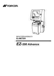
USER MANUAL<br />
COMPUTERIZED LENSMETER<br />
CL-300
INTRODUCTION<br />
Thank you for purchasing the TOPCON Computerized Lensmeter CL-300.<br />
FEATURES<br />
This instrument has the following features:<br />
• High accuracy measurements with ease of operation<br />
• The LCD touch panel will facilitate operation<br />
PURPOSE OF THIS MANUAL<br />
This Instruction Manual covers an overview of the TOPCON Computerized Lensmeter CL-<br />
300, basic operations, troubleshooting, maintenance and cleaning.<br />
To ensure the efficient, safe use, read through “DISPLAYS AND SYMBOLS FOR SAFE USE”<br />
and “GENERAL SAFETY INFORMATION” and use the instrument correctly.<br />
Keep this Instruction Manual within reach for future reference.<br />
1
1. No part of this <strong>manual</strong> may be copied or reprinted, in whole or in part, without<br />
prior written permission.<br />
2. The contents of this <strong>manual</strong> are subject to change without prior notice and without<br />
legal obligation.<br />
3. The contents of this <strong>manual</strong> are correct to the best of our knowledge. Please<br />
inform us of any ambiguous or erroneous descriptions, missing information, etc.<br />
©2012 TOPCON CORPORATION<br />
ALL RIGHTS RESERVED<br />
2
CONTENT<br />
INTRODUCTION ........................................................................................................1<br />
GENERAL SAFETY INFORMATION..........................................................................5<br />
HOW TO READ THIS MANUAL.................................................................................6<br />
GENERAL MAINTENANCE INFORMATION .............................................................6<br />
USER MAINTENANCE...............................................................................................6<br />
DISCLAIMERS ...........................................................................................................6<br />
DISPLAYS AND SYMBOLS FOR SAFE USE............................................................7<br />
SYMBOLS ..................................................................................................................7<br />
WARNING INDICATIONS AND POSITIONS .............................................................8<br />
COMPONENTS<br />
ACCESSORIES..........................................................................................................9<br />
COMPONENT NAMES.............................................................................................10<br />
COMPARTMENT SPACE.........................................................................................11<br />
OPERATION METHOD OF CONTROL ...................................................................11<br />
CONTROL PANEL COMPONENTS.........................................................................12<br />
MEASUREMENT SCREEN......................................................................................14<br />
SETUP SCREEN......................................................................................................17<br />
PREPARATION<br />
INSTALLATION ........................................................................................................18<br />
SETTING THE PAPER.............................................................................................19<br />
AUTO POWER SAVE FUNCTION ...........................................................................20<br />
USING THE INSTRUMENT<br />
CHECKING BEFORE MEASURING ........................................................................21<br />
SETTING OF A LENS ..............................................................................................21<br />
MEASURING A SINGLE FOCAL LENS ...................................................................22<br />
MEASURING A PROGRESSIVE LENS ...................................................................24<br />
MEASURING BI-FOCAL AND TRI-FOCAL LENSES...............................................28<br />
MEASURING BI-FOCAL AND TRI-FOCAL LENSES (MEASURING THE DIOPTER<br />
POWER OF LENSES WITH THE CONCAVE SIDE UP) .........................................29<br />
MEASURING A CONTACT LENS............................................................................30<br />
A:STEP MODE .........................................................................................................32<br />
UV TRANSMISSION MEASUREMENT....................................................................32<br />
AXIS MARKING<br />
(CARTRIDGE SPECIFICATION/STEEL NEEDLE SPECIFICATION) .....................34<br />
PRINTING ADDITIONAL TEXTBOX (WITH PRINTER SPECIFICATION) ..............37<br />
SETTING A SEQUENCE NO. ..................................................................................38<br />
LENS PROTECTION PAD .......................................................................................38<br />
MEASURING PD (PD FITTING) (WITH PD SPECIFICATION)................................39<br />
HOW TO OUTPUT DATA.........................................................................................41<br />
3
SETTING FUNCTIONS ON SETUP SCREEN<br />
OPERATING THE SETUP SCREEN........................................................................42<br />
LIST OF SETUP ITEMS ...........................................................................................45<br />
MAINTENANCE ........................................................................................................49<br />
BEFORE REQUESTING SERVICE<br />
CAUTION MESSAGES ............................................................................................51<br />
CHECK ITEMS .........................................................................................................51<br />
SPECIFICATIONS<br />
SPECIFICATIONS....................................................................................................52<br />
WITH PRINTER SPECIFICATION ...........................................................................52<br />
OPTIONAL ACCESSORIES.....................................................................................52<br />
GENERAL INFORMATION ON USAGE AND MAINTENANCE<br />
ENVIRONMENTAL CONDITIONS FOR USE ..........................................................53<br />
STORAGE, USAGE PERIOD AND OTHERS ..........................................................53<br />
SAFETY DESIGNATIONS PER IEC 60601-1 STANDARD .....................................53<br />
MAINTENANCE AND CHECKS ...............................................................................54<br />
DISPOSAL................................................................................................................54<br />
INTENDED USER PROFILE ....................................................................................54<br />
ELECTROMAGNETIC COMPATIBILITY..................................................................55<br />
SHAPE OF PLUG.....................................................................................................59<br />
USING THE INSTRUMENT AS A SYSTEM<br />
ON - LINE SYSTEM .................................................................................................60<br />
4
GENERAL SAFETY INFORMATION<br />
WARNINGS<br />
Preventing Electric Shocks and Fire<br />
To avoid fire and electric shocks, do not place a cup or vessel containing water/fluid on the<br />
instrument.<br />
To avoid electric shocks, do not insert objects through vent holes or gaps or force them<br />
inside the machine body.<br />
To avoid electric shocks, do not attempt disassembling, rebuilding or repairing. For repairs,<br />
call your dealer.<br />
To avoid fire/electric shocks, do not install the instrument in a place where it may get wet.<br />
If there is a malfunction or if the instrument produces smoke, immediately turn OFF the<br />
POWER switch and unplug the power cable. To a avoid a possible fire due to malfunction,<br />
call your dealer and ask for repairs.<br />
CAUTIONS<br />
Ensuring the Safety of Patients and Operators<br />
To avoid injury by falling, do not install the instrument on a slope or in an unstable place.<br />
Preventing Electric Shocks and Fire<br />
Do not open the cover. For repairs, contact your Topcon dealer.<br />
[The instrument may injure someone by electric shock.]<br />
Electromagnetic Compatibility (EMC)<br />
This instrument has been tested (with120V/ 230V) and found to comply with IEC60601-1-2<br />
Ed.3.0:2007. This instrument radiates radio frequency energy within standard and may affect<br />
other devices in vicinity. If you have found out by turning on/off the instrument that it affects<br />
other devices, it is recommended to change the direction, keep a proper distance against<br />
other devices or change the outlet. If you have a question, consult with the selling agent.<br />
5
HOW TO READ THIS MANUAL<br />
• Read the instructions on pages 5 to 8 before using the machine.<br />
• If you would like an overview of the system, begin by reading "USING THE INSTRU-<br />
MENT"(page 21).<br />
• For setting various functions, see "SETTING FUNCTIONS ON SETUP SCREEN" on page<br />
42.<br />
GENERAL MAINTENANCE INFORMATION<br />
USER MAINTENANCE<br />
To maintain the safety and performance of the equipment, never attempt to repair or perform<br />
maintenance. These tasks should be performed by an authorized service representative.<br />
Maintenance tasks that can be performed by the user are as follows; for details, follow the<br />
<strong>manual</strong>’s instructions.<br />
CLEANING COVER GLASSES<br />
For details, see page 50 of this <strong>manual</strong>.<br />
DISCLAIMERS<br />
• TOPCON shall not take any responsibility for damages due to fire, groundquake, actions by<br />
third person, or the negligence and misuse by the user and used under unusual conditions.<br />
• TOPCON shall not take any responsibility for damage derived from the inability to use this<br />
equipment, such as a loss of business profit and suspension of business.<br />
• TOPCON shall not take any responsibility for damage caused by operations other than<br />
those described in this Instruction Manual.<br />
6
DISPLAYS AND SYMBOLS FOR SAFE USE<br />
In order to encourage the safe use of this product, warnings labels are placed on the product and<br />
written in the instruction <strong>manual</strong>.<br />
We suggest that everyone understands the meaning of the following displays and icons before<br />
reading the “GENERAL SAFETY INFORMATION” and text.<br />
DISPLAYS<br />
Display<br />
WARNINGS<br />
CAUTIONS<br />
NOTES<br />
Meaning<br />
Indicates a potentially hazardous situation which, if not<br />
avoided, could result in death or serious injury.<br />
Indicates a potentially hazardous situation which, if not<br />
avoided, may result in minor or moderate injury.<br />
Useful functions to know and attentions to prevent<br />
troubles are noted.<br />
SYMBOLS<br />
Symbol IEC/ISO Publication Description Description (French)<br />
IEC 60417-5032 Alternating Current Courant alternatif<br />
IEC 60417-5008<br />
Off (power: disconnection<br />
from the main power supply)<br />
Éteint (courant: coupure<br />
avec le secteur)<br />
IEC 60417-5007<br />
ISO 7010-W001<br />
On (power: connection to<br />
the main power supply)<br />
General warning sign<br />
Allumé (courant: raccordement<br />
sur le secteur)<br />
Symbole d'avertissement<br />
général<br />
7
WARNING INDICATIONS AND POSITIONS<br />
To insure safety, warning labels are provided.<br />
Use the equipment correctly by following the warning instructions. If any of the following labels<br />
are missing, please contact us at the address stated on the back cover.<br />
1<br />
No. Label Meaning<br />
1<br />
WARNING<br />
To avoid injury caused by electric shock, do not open the cover.<br />
Ask your dealer for service.<br />
WARNING<br />
To avoid injury, do not touch the AC adapter jack while using the<br />
AC adapter.<br />
8
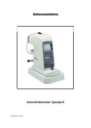
INSTRUCTION MANUAL<br />
COMPONENTS<br />
ACCESSORIES<br />
The following are standard accessories. Make sure that all these items are included (quantity).<br />
Power cable (1) Lens protection pad (1)<br />
AC adapter (1) Model name: BPM040S09F02 Silicon cloth (1)<br />
Contact lens support (1) Dust cover (1)<br />
Printer paper (2)<br />
(with printer specification)<br />
User <strong>manual</strong> (1)<br />
Instruction <strong>manual</strong> (1)<br />
COMPUTERIZED LENSMETER<br />
CL-300<br />
Guarantee sheet (1)<br />
9<br />
COMPONENTS
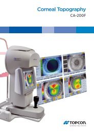
COMPONENT NAMES<br />
with PD<br />
Back side<br />
Nose reset<br />
Port cover<br />
LCD<br />
Power LED<br />
Power switch<br />
Axis marker lever<br />
Lens retainer<br />
Lens table<br />
Lens support<br />
MEMORY button<br />
Marking ink<br />
cartridge<br />
Lens table<br />
lever<br />
AC adapter<br />
jack<br />
*LAN<br />
IN<br />
OUT<br />
RS-232C<br />
IN<br />
OUT<br />
USB<br />
Printer<br />
cover<br />
*The model without LAN is also provided.<br />
• Use a LAN cable within 30m.<br />
• The USB is for maintenance, not used normally.<br />
• Power LED<br />
Orange lamp ON: Power OFF<br />
Green lamp ON: Power ON<br />
Green lamp blinks: Under power save<br />
• The model without PD and LAN function is not provided nose-pad and LAN.<br />
10<br />
COMPONENTS
COMPARTMENT SPACE<br />
A space for keeping the contact lens holder, printer paper, etc. is secured in the back.<br />
OPERATION METHOD OF CONTROL<br />
The control panel is a touch panel. Do not use any sharp tools; e.g. ball point pen.<br />
Tap To select any relevant item. Continue to press Used for long button press.<br />
Touch the screen softly with a finger.<br />
Continue to touch the screen softly with a finger.<br />
11<br />
COMPONENTS
CONTROL PANEL COMPONENTS<br />
THE FUNCTION BUTTONS<br />
The control panel is designed as a touch panel for performing various operations and settings.<br />
It displays images and shows information, including set conditions and measurement results.<br />
SINGLE MODE<br />
S button<br />
R button<br />
Measurement mode<br />
Settings button<br />
+/- button<br />
STEP button<br />
Prism button<br />
CLEAR button<br />
PRINT button<br />
UV button<br />
R/L MODE<br />
L button<br />
R button<br />
12<br />
COMPONENTS
BUTTON NAMES<br />
Settings button<br />
Displays the SETUP screen.<br />
+/- button Used to change the degree (performed when an orange frame<br />
is displayed).<br />
STEP button<br />
Prism button<br />
Used to change the step of measurement value.<br />
(Press it long time for A:step setting.)<br />
Long button press:<br />
Used to change the prism display.<br />
UV button<br />
Used to change ON/OFF of UV measurement.<br />
(performed when an orange frame is displayed).<br />
PRINT button<br />
CLEAR button<br />
Press to obtain a print out readings.<br />
Press to output data trough RS-232C.<br />
Used to delete all data in memory.<br />
To delete R and L separately, hold the button down.<br />
Measurement mode button<br />
Used to change the setting of measurement mode.<br />
13<br />
COMPONENTS
MEASUREMENT SCREEN<br />
SINGLE MODE<br />
Lens measurement value<br />
Target<br />
Message bar<br />
OFF CENTER<br />
ERROR<br />
ALIGNMENT OK<br />
MARKING OK<br />
Setup icon<br />
Refer to<br />
LIST OF SETUP ITEMS<br />
R/L MODE<br />
Measurement value of<br />
left-eye lens<br />
Measurement value of<br />
right-eye lens<br />
• When saved, S/R/L changes the color and stops.<br />
• When the measurement value turns white, the measurement is finished.<br />
• When the measurement value is yellow, the measurement of a multi-focal lens is being performed.<br />
14<br />
COMPONENTS
TARGET<br />
Optical center's off.<br />
[OFF CENTER] is displayed<br />
when the optical center is off<br />
by 4 or more.<br />
Blue: , measurement value<br />
[ALIGNMENT OK]<br />
mark appears when the<br />
lens is ready for measurement.<br />
Green: , measurement value<br />
[MARKING OK]<br />
Place in mark, the lateral<br />
line will extend, getting the<br />
instrument ready for marking.<br />
Pink: , measurement value<br />
The target indicates optical center position.<br />
And it varies depending on the symbol used in the spherical equivalent power.<br />
Be noted that the target motion is different from that of Topcon telescopic lensmeters.<br />
For axis marking procedures, don't use target's position but the prism value.<br />
Refer the instruction in Page 27.<br />
15<br />
COMPONENTS
RESULT DISPLAY<br />
When INITIAL/DISPLAY/NORMAL<br />
is selected, the display is normal.<br />
When INITIAL/DISPLAY/HORIZONTAL LARGE<br />
enlarged.<br />
is selected, the SCA display is horizontally<br />
When INITIAL/DISPLAY/VERTICAL LARGE is selected, the SCA display is vertically<br />
enlarged. The graphic moves to the opposite side.<br />
16<br />
COMPONENTS
SCREEN PRINT DISPLAY: (WHEN ENLARGED)<br />
For framed lenses, of which both R and L are memorized, pressing the PRINT button enlarges<br />
the SCA of both eyes. To return to the original state, tap the button.<br />
The button which is not allowed change.<br />
• When the setting is PRINT/AUTO PRINT/ON , printing is performed automatically<br />
after saving the measurement value of both eyes.<br />
• By tapping the button, the measurement screen is returned, leaving measurement<br />
values as saved.<br />
• By tapping the button, the measurement screen is returned, clearing measurement<br />
values.<br />
SETUP SCREEN<br />
The Setup screen is displayed by tapping the Settings button<br />
on Measurement screen.<br />
17<br />
COMPONENTS
PREPARATION<br />
INSTALLATION<br />
WARNING<br />
To avoid fire/electric shocks, connect the power plug to a 3P<br />
AC outlet (with ground) and secure grounding.<br />
CAUTION<br />
To avoid injury by falling, do not install the instrument on a<br />
slope or in an unstable place.<br />
1 Remove the tape from the lens support.<br />
2 Remove the tape from the marking ink cartridge.<br />
3 Remove the port cover. Push the etched mark and move the cover to the arrow direction.<br />
Etched mark<br />
4 Plug in the power cable to the AC adapter.<br />
5 Pass the cable through the cable clamp.<br />
6 Connect the AC adapter plug to the AC adapter jack located on the rear panel of the main<br />
body.<br />
IN<br />
OUT<br />
AC adapter cable<br />
Cable clamp<br />
18<br />
PREPARATION
7 Setting the Port Cover.<br />
Etched mark<br />
The stop to be<br />
fitted first<br />
Fit the stop of the figure above to the<br />
main body. After fitting the stop, turn<br />
the cover along the arrow direction.<br />
Fit the stop by pushing<br />
the etched mark.<br />
By connecting an AC adapter, the main body starts automatically.<br />
SETTING THE PAPER<br />
1 Press the PRINTER button and open the cover.<br />
2 Open the printer cover to the limit.<br />
19<br />
PREPARATION
3 Insert the printer paper in the direction shown below and pull out the paper end to your<br />
side by 7 to 8cm.<br />
4 Bring the paper into the center, then close the printer cover.<br />
• Printer feed function: Hold PRINTER button down.<br />
• In case the printer cover is not firmly closed, printing will not start.<br />
• A 58mm wide paper roll (example: TP-50KJ-R [Nippon Paper Co.]) is recommended.<br />
Other paper rolls may cause abnormal printing noise or unclear print.<br />
AUTO POWER SAVE FUNCTION<br />
1 When switch/tap operations are not done for about 10 minutes, or if no patient lens is set,<br />
power save starts automatically.<br />
2 During power save, the screen saver is actuated.<br />
3 When the Memory button is pressed continuously for more than 2 seconds, the<br />
backlight of the monitor goes off and the Power switch LED blink.<br />
4 For reset, either tap the monitor, or press the Memory button, or press the Power switch<br />
. Incidentally, press the Power switch short, or if pressed and held long, the<br />
power is shut off<br />
5 If auto power save function is not required, select INITIAL/AUTO OFF/NO .<br />
6 To actuate power save <strong>manual</strong>ly, press the Memory button longer than 2 seconds.<br />
20<br />
PREPARATION
USING THE INSTRUMENT<br />
CHECKING BEFORE MEASURING<br />
1 Check to see that there is no lens on the lens support.<br />
2 Turn on the power switch.<br />
3 Display will appear on the screen in a few seconds.<br />
The ERROR screen will appear when there is a<br />
lens left on the lens support or dust left on the<br />
cover glass. Remove the lens or dust.<br />
By tapping the screen, the error screen is cleared.<br />
SETTING OF A LENS<br />
A SINGLE LENS SETTING<br />
1 Place the lens with the concave surface facing down on the lens support.<br />
2 Lift and place down the lens retainer.<br />
3 When holding a sharp-curve lens, provide your hand in case the lens falls.<br />
A FRAMED LENS SETTING<br />
1 Place the flamed lens on the lens support.<br />
2 Turn the lens table lever and place the glass frame<br />
against the lens table for measurement.<br />
Alignment<br />
Right and left....Place the frame against the lens<br />
table, and move the frame right<br />
and left finely.<br />
Vertically ..........Move the table finely with the<br />
lens table lever.<br />
3 Lift and place down the lens retainer.<br />
21<br />
USING THE INSTRUMENT
MEASURING A SINGLE FOCAL LENS<br />
When a measurement mode button is<br />
INITIAL/PROGRESSIVE/AUTO<br />
,<br />
, a single focal lens can be measured.<br />
INITIAL/PROGRESSIVE/OFF<br />
1 Move the lens and move the target near the center.<br />
2 ALIGNMENT OK will be displayed when the target image center is within the minimum circle<br />
(0.5 or smaller).<br />
3 The MARKING OK is displayed when the target image center is reached. If is displayed,<br />
"single focal lens" is memorized automatically.<br />
When BEEP function is ON, the buzzer will sound.<br />
(Note) The target may move in a contrary manner immediately after the lens is placed.<br />
WHEN R/L DESIGNATION IS REQUIRED:<br />
Tap the R button. The R/L display screen is displayed.<br />
By tapping the L button, L is displayed. By tapping the CLEAR button, S is returned.<br />
Single lens<br />
R lens<br />
R button<br />
CLEAR button<br />
CLEAR button<br />
L button<br />
R button<br />
L lens<br />
• When the setting is INITIAL/AUTO R/L/ R/L , the Single Lens screen is<br />
returned by tapping the CLEAR button.<br />
• By tapping the CLEAR button, saved measurement values are cleared.<br />
22<br />
USING THE INSTRUMENT
MANUAL SAVING:<br />
Press the Memory button . The flicker-zooming “S” stops at the zoomed-up state and the<br />
color is changed. (When R/L is displayed, R and L are changed.)<br />
• When printing<br />
Tap the PRINT button<br />
. When connecting with computer, data is transmitted.<br />
MEASURING A FRAMED LENS<br />
• When INITIAL/AUTO R/L OFF is set. ( is not displayed):<br />
Tap the R button.<br />
First align the right lens and press the Memory button .<br />
Tap the L button.<br />
Align the left lens and press the Memory button .<br />
• When INITIAL/AUTO R/L / R/L & INITIAL/AUTO MEMORY/ON is set.<br />
( are displayed):<br />
*Measurement of framed lens.<br />
First, align the right lens to display “MARKING OK”. Then the result is automatically memorized,<br />
when the right lens is hold.<br />
Removing the right lens will automatically move to the L measurement.<br />
Align the left lens, then the result is automatically memorized, when the left lens is hold.<br />
• When INITIAL/AUTO R/L/ R/L & INITIAL/AUTO MEMORY/ S:OFF R/L:ON is set.<br />
( are displayed):<br />
*Measurement of single lens/framed lens<br />
Tap the R button. ( is displayed)<br />
At first, align the right lens to display "MARKING OK". Then the result is automatically memorized,<br />
when the right lens is hold.<br />
Removing the right lens will automatically move to the L measurement.<br />
Align & hold the left lens. The result is automatically memorized.<br />
23<br />
USING THE INSTRUMENT
MEASURING A PROGRESSIVE LENS<br />
When a measurement mode button is or , a progressive lens can be measured.<br />
When auto progressive recognition mode is on. INITIAL/PROGRESSIVE/AUTO<br />
Discrimination of single focal lens and progressive focal lens can be done, which is not<br />
easily possible from appearance.<br />
When progressive only is set. INITIAL/PROGRESSIVE/PROGRESSIVE ONLY<br />
The auto progressive recognition measurement can be omitted. Start measurement from<br />
step 3 below.<br />
1 Measure the lower frame center<br />
(position in the measurement mode button 1 );<br />
If the measurement is finished, Measurement mode button<br />
The figure blinks and<br />
the size changes.<br />
changes to .<br />
2 Measure the frame center<br />
(position in the measurement mode button 2 );<br />
If the difference is over 0.50D or more, the screen changes.<br />
The figure blinks and<br />
the size changes.<br />
3 Measure progressive lens for distance vision. (Excluding horizontal prism prescription<br />
lenses) By moving the frame in all directions along the arrow mark displayed on the<br />
screen, align with .<br />
24<br />
USING THE INSTRUMENT
4 When the distance vision measurement is obtained and saved, the screen automatically<br />
changes to the near vision measurement display.<br />
(The distance vision region can be easily detected, as you repeat moving and stopping<br />
the lens little by little at measuring.)<br />
• By pressing the Memory button , you may <strong>manual</strong>ly store<br />
the result of distance vision power measurement. The screen<br />
will then switch to the near vision measurement.<br />
When INITIAL/FAR MEMORY/OFF is selected as the<br />
default setting, the result of the distance vision measurement is<br />
not automatically stored. With this setting, you must press the<br />
Memory button to save the distance vision.<br />
• For high-power lenses, sometimes the distance vision region<br />
cannot be easily detected. In this case, obtain the measurement in the approximate<br />
position that is shown on the above, and then press Memory button .<br />
10mm approx.<br />
• For horizontal prism prescription lenses, press the MEMORY button<br />
distance reference point.<br />
at the<br />
eye point<br />
10mm approx.<br />
5 Measure progressive lens for near vision.<br />
While watching the screen, draw out the lens table forward: the bar-meter extends and the<br />
“+” appears. To bring this “+” to the bar-meter center, swing the lens right-left and extend<br />
the bar-meter.<br />
25<br />
USING THE INSTRUMENT
6 The condition illustrated below indicates that a position outside of the progressive zone is<br />
being measured. Move the lens in the direction of the arrow to bring the "+" into the center<br />
of the progressive zone.<br />
7 The “+” becomes larger as it comes closer to the near vision position.<br />
8 The ADD power is saved, the progressive lens measurement is completed.<br />
Knock-out black<br />
1.42<br />
• By pressing the MEMORY button , you may <strong>manual</strong>ly store the result of<br />
near vision power measurement.<br />
When INITIAL/NEAR MEMORY/OFF is selected as the default setting, the<br />
result of the near vision measurement is not automatically stored. With this setting,<br />
you must press the MEMORY button to save the near vision.<br />
• When measuring a lens mounted in a large frame,<br />
the ADD power may be higher because some lenses<br />
increase the ADD power at a position below the near<br />
vision region. Accordingly, if the lens is measured at<br />
a point lower than the near vision eye point, the ADD<br />
power reading may be higher. If you want to know<br />
the accurate prescription, it is advisable to check the<br />
measurement position at the hidden mark.<br />
26<br />
USING THE INSTRUMENT
ASPHERICAL RANGE PROGRESSIVE RECOGNITION<br />
If a progressive lens is position so that the lens is outside of the progressive zone, the icon<br />
of a screen bottom will change to . By tapping the button, the screen will automatically<br />
switch to the distance vision measurement screen.<br />
This appears when measuring the aspherical range of the progressive lens.<br />
When the<br />
button is displayed, auto saving is not available.<br />
MEASURING AN UNPROCESSED PROGRESSIVE LENS<br />
As each unprocessed lens has a mark on the measuring point. Do measurement on the<br />
mark position.<br />
Distance vision region marked<br />
Near vision region marked<br />
• The measuring point for the distance or near vision region may be narrowed by<br />
marks. Take care that the luminous flux may not be shaded during measurement.<br />
ADD values will flicker when the luminous flux is shaded by marks or off the progressive<br />
zone at the time of measuring the near vision region.<br />
An EX lens may not be provided with accurate measurements when measured<br />
in the boundary.<br />
• When the Setup screen appeared in the middle of measurement, measurement<br />
values are cleared when the Measurement screen is returned.<br />
27<br />
USING THE INSTRUMENT
MEASURING BI-FOCAL AND TRI-FOCAL LENSES<br />
When a measurement mode button is<br />
, bi-focal and tri-focal lenses can be measured.<br />
INITIAL/PROGRESSIVE/AUTO , INITIAL/PROGRESSIVE/OFF<br />
1 Align the distance vision in the center of the target image and press the MEMORY button<br />
.<br />
2 Move the lens into the near vision region (bi-focal segment).<br />
3 Press the Memory button (Near Vision Measurement Start button in this case).<br />
The measurement mode button is changed to .<br />
4 Measure the bi-focal power and press the MEMORY button again.<br />
To measure the 2 nd near vision of tri-focal lenses, storing the 1 st mid vision power automatically<br />
changes the button to the button. Tap the button starts the near vision<br />
measurement.<br />
ADD : +1.75<br />
+2.50<br />
When the Setup screen appeared in the middle of measurement, measurement<br />
values are cleared when the Measurement screen is returned.<br />
28<br />
USING THE INSTRUMENT
MEASURING BI-FOCAL AND TRI-FOCAL LENSES (MEASURING THE<br />
DIOPTER POWER OF LENSES WITH THE CONCAVE SIDE UP)<br />
Measurement is possible when the measurement mode is .<br />
INITIAL/PROGRESSIVE/REVERSE<br />
1 Set the lens with the concave side down as<br />
usual, align the distance vision region, and<br />
press the MEMORY button .<br />
Lens position<br />
Screen<br />
2 Set the lens with the concave side up, align the<br />
distance vision region, and press the MEMORY<br />
button .<br />
3 Leaving the lens with the concave side up, align<br />
the near vision region and press the MEMORY<br />
button .<br />
When the Setup screen appeared in the<br />
middle of measurement, measurement<br />
values are cleared when the Measurement<br />
screen is returned.<br />
29<br />
USING THE INSTRUMENT
MEASURING A CONTACT LENS<br />
MEASURING A HARD CONTACT LENS<br />
1 Replace the lens support with the contact lens support.<br />
2 Select INITIAL/LENS/HARD CONTACT . Setup icon will be displayed on the<br />
screen.<br />
3 Put the contact lens on contact lens support with special tweezer.<br />
Tweezer<br />
30<br />
USING THE INSTRUMENT
MEASURING A SOFT CONTACT LENS WITHOUT ASTIGMATISM<br />
A soft contact lens cannot be accurately measured because of its structure.<br />
Although you can measure a soft contact lens power in following way, consider the<br />
results an average and not the exact value.<br />
1 Use the contact lens support for measuring as measuring a hard contact lens.<br />
2 Select INITIAL/LENS/SOFT CONTACT . Setup icon will be displayed on the<br />
screen.<br />
3 Pinch the soft contact lens with special tweezers to remove moisture from the lens. Put<br />
the lens between paper and move three times to remove moisture from the surface.<br />
If there is moisture on the soft contact lens surface, it is not possible to measure<br />
because the luminous flux malfunctions.<br />
4 If there is moisture dews on the surface when the contact lens is held to the light, put the<br />
lens in the special solution again, and repeat the above. Moreover, take care about turning<br />
inside out. When in the normal position, the lens looks like a bowl. However, when the<br />
lens turns inside out, the rim looks warped. If the lens is ready for measurement, place it<br />
on the contact lens holder and observe the shape (with tweezers) for alignment. After 30<br />
seconds or more, the lens power changes since the internal moisture evaporates, therefore,<br />
measure it as quickly as possible.<br />
Use the hard contact mode when measuring a toric soft contact lens.<br />
When Contact Lens is selected, the measurement mode button is changed to<br />
, and this cannot be changed.<br />
31<br />
USING THE INSTRUMENT
A:STEP MODE<br />
Select INITIAL/A:STEP/5 and hold STEP button down, change to the A:STEP<br />
button.<br />
The axial angle is rounded to 5°.<br />
It is convenient for inputting the result by doing measurement with the trial lens left in the<br />
temporary frame.<br />
For release, press the<br />
Return to the STEP button<br />
button long.<br />
, the 5° rounding is reset.<br />
STEP of the measurement value is the state before changing to the temporary<br />
frame (A:step).<br />
UV TRANSMISSION MEASUREMENT<br />
UV Transmission Measurement is available when the UV button is orange-framed .<br />
If not orange-framed, tap the UV button and make it orange-framed.<br />
1 Move the lens and move the target near the center.<br />
2 ALIGNMENT OK is displayed when the target image center is within the smallest circle<br />
(within 0.5 ).<br />
3 MARKING OK is displayed when the target image center is reached.<br />
4 Press the Memory button .<br />
5 The SCA value is saved, and the UV transmission measurement value is displayed in a<br />
few seconds.<br />
After pressing the Memory button , do not move the lens until an UV transmission<br />
measurement value is displayed.<br />
UV transmission<br />
measurement value<br />
32<br />
USING THE INSTRUMENT
CORRECTING THE UV TRANSMISSION<br />
If UV transmission is not 100% after removing the lens, perform correction.<br />
1 Confirm that no lens is put on the lens support.<br />
2 Press and hold the UV button.<br />
3 When correction is finished, the buzzer beeps.<br />
During the UV transmission measurement/correction, do not look into the LED<br />
irradiation part.<br />
LED irradiation part<br />
33<br />
USING THE INSTRUMENT
AXIS MARKING<br />
(CARTRIDGE SPECIFICATION/STEEL NEEDLE SPECIFICATION)<br />
Using the cartridge, one light touch to the lens can put a clear ink mark.<br />
MARKING A LENS WITHOUT ASTIGMATISM<br />
1 Move the lens until the centering mark coincides with the target image completely, and<br />
MARKING OK will appear.<br />
Centering mark<br />
2 Depress the marking lever to mark the lens.<br />
Line extends laterally to the target<br />
34<br />
USING THE INSTRUMENT
MARKING A LENS WITH ASTIGMATISM<br />
• Axis marking, maintaining the axis as prescribed<br />
Align the target image with the center mark, approximating the axis angle mark to the angle as<br />
prescribed. Finally, adjust by the numerical display of axis angle A:.<br />
Before performing alignment, set auto memory to off.<br />
Confirm is not displayed at the setup icon.<br />
Check here<br />
Axis angle mark (every 5°)<br />
• Marking a cylindrical axis<br />
Match the center mark with the target image, approximating the axis angle mark to 180<br />
degrees.<br />
Adjust A of the axis angle to 180 degrees.<br />
Adjust to 180°.<br />
Axis angle mark (every 5°)<br />
35<br />
USING THE INSTRUMENT
MARKING A LENS WITH PRISM POWER<br />
• When the prescription is displayed with X-Y (orthogonal<br />
coordinates) ( INITIAL/PRISM/X-Y )<br />
Tap the prism button and get display.<br />
Carry out aligning according to the prism value as<br />
prescribed and as displayed on the screen.<br />
I in prism value: Base In<br />
O in prism value: Base Out<br />
U in prism value: Base Up<br />
D in prism value: Base Down<br />
• When the prescription is displayed with P-B (polar coordinates)<br />
( INITIAL/PRISM/P-B )<br />
Tap the prism button and get display.<br />
Carry out aligning according to the prism value as<br />
prescribed and as displayed on the screen.<br />
P: Prism value<br />
B: Base orientation<br />
Take care that the polar coordinates are not the<br />
same as the value on the angular scale in the<br />
target image.<br />
• When the unit is mm ( INITIAL/PRISM/mm )<br />
Tap the prism button and get display.<br />
The<br />
marks show the optical center<br />
reaches the center of measurement by moving the<br />
lens in the arrow directions by the distance as displayed.<br />
: 3.0mm<br />
: 2.0mm The position is shown in the right figure.<br />
• 0 will be displayed if the spherical power S is around 0.<br />
• When the prism value is more than 10 (vertical direction), the measurement<br />
value is recognized as a reference value. For reference value, * (asterisk) is displayed<br />
at the measurement result. Measurement values recognized as reference<br />
value: SCA value, prism value, ADD value<br />
36<br />
USING THE INSTRUMENT
PRINTING ADDITIONAL TEXTBOX (WITH PRINTER SPECIFICATION)<br />
On the print out with the measuring data, the user can input his own text, like office name,<br />
address or special message. The available space is three line of 24 characters each.<br />
Tap the PRINT/NAME/INPUT .<br />
Text enter screen will appear.<br />
Enter window<br />
Tap the desired enter window, tap the button and input with keyboard.<br />
Setting is completed by tapping the OK button.<br />
Printout<br />
Printing the<br />
additional textbox<br />
37<br />
USING THE INSTRUMENT
SETTING A SEQUENCE NO.<br />
Setting is carried out when writing a sequence No. on printing paper and transferring the<br />
serial No., using RS-232C.<br />
Tap the INITIAL/SEQ.NO./INPUT , and the screen as shown below will appear.<br />
Enter numerals and fix by tapping the OK button.<br />
No printing or counting is carried out in case of 0000.<br />
Press MEMORY button , PRINT button and CLEAR button in this order,<br />
and counting will be carried out. (except for single lens).<br />
If the OK button is tapped without filling all 4 digits, the empty digit is saved as "0."<br />
Example) 12 OK<br />
0012 is saved.<br />
LENS PROTECTION PAD<br />
The attached lens protection pad allows a soft contact with the measuring lens.<br />
1 Fit the lens protection pad according to the instructions.<br />
2 Select INITIAL/LENS/NORMAL(PAD) , and the measurement result will be automatically<br />
compensated.<br />
38<br />
USING THE INSTRUMENT
MEASURING PD (PD FITTING) (WITH PD SPECIFICATION)<br />
1 Select INITIAL/PD/ON .<br />
2 Put the spectacle frame onto the nose rest.<br />
Nose rest<br />
Lens support<br />
3 Align the lens until marking is OK. OK if the spectacle frame is horizontal along the lens<br />
table line. If the spectacle frame has a camber, align it horizontally.<br />
Errors will appear when the spectacle frame is not horizontally aligned.<br />
RPD<br />
4 Press the lens retainer since the lens is in contact with the lens support sideways.<br />
Let your hand go with the spectacle frame to prevent PD value shifting.<br />
5 Press Memory button.<br />
39<br />
USING THE INSTRUMENT
6 Follow the similar steps to measure the lens on the opposite side.<br />
Totaled PD will be displayed.<br />
7 Bring the nose rest to the extreme right and fold it. It will stick to the lens table by means of<br />
a magnet.<br />
Range 25~45mm on one side (minimum 0.5mm)<br />
If the measured PD value differs from that of marking PD.<br />
8 Difference may occur by the measurement technique and with low-power lenses having a<br />
large camber angle.<br />
No camber angle<br />
A camber angle<br />
Marking PD<br />
0 flux<br />
Marking<br />
Since the optical center of the glasses mounted for<br />
the infinite far is searched, the measured PD value<br />
of CL-300 is called the PD/fitting value.<br />
Principal point<br />
PD fitting<br />
(by PD mechanism)<br />
When the pupil is on the marking<br />
position in the case of a concave<br />
lens, a prism is added outside.<br />
40<br />
USING THE INSTRUMENT
HOW TO OUTPUT DATA<br />
OUTPUT USING RS232C<br />
This instrument can output data to a PC, etc. via the RS232C interface.<br />
1 Connect the RS232C cable to RS232C OUT.<br />
2 Connect the other end of the cable to the PC., etc.<br />
3 Confirm that set up of data communication settings.<br />
For details, refer to “DATA COMMUNICATION (COMM.)” on page 47.<br />
4 Perform measurements.<br />
5 Tap the PRINT button of the control panel.<br />
Data is outputted to the connected external device.<br />
OUTPUT USING LAN<br />
This instrument can output data to a PC, etc. via the LAN interface.<br />
1 Connect the network cable to LAN OUT.<br />
2 Connect the other end of the cable to the PC., etc.<br />
3 Confirm that set up of LAN connection settings.<br />
For details, refer to “LAN CONNECTION (LAN)” on page 48.<br />
4 Perform measurements.<br />
5 Tap the PRINT button of the control panel.<br />
Data is outputted to the connected external device.<br />
41<br />
USING THE INSTRUMENT
SETTING FUNCTIONS ON SETUP SCREEN<br />
OPERATING THE SETUP SCREEN<br />
Various functions can be set on the SETUP screen.<br />
PREPARATONS FOR SETTING<br />
1 Make sure that the power cable is connected.<br />
For connection, refer to “PREPARATION” on page 18.<br />
2 Turn ON the POWER switch.<br />
3 Tap the SETTINGS button on the control panel.<br />
SETTINGS button<br />
The SETUP screen is displayed.<br />
Back Page button<br />
Page display<br />
Next Page button<br />
Index<br />
Return button<br />
Descriptions<br />
Current condition button<br />
By tapping a current condition button,<br />
the options buttons are displayed.<br />
42<br />
SETTING FUNCTIONS ON SETUP SCREEN
OUTLINE OF SETUP SCREEN OPERATIONS<br />
1 Tap INDEX and select the subject of setting.<br />
2 Operate the NEXT PAGE button or BACK PAGE button , as necessary, and display<br />
the page to confirm/change.<br />
3 Tap the Current condition button of the item to be changed and find the options button.<br />
Options button<br />
4 Tap the options button and change the setting.<br />
43<br />
SETTING FUNCTIONS ON SETUP SCREEN
• Instead of the options button, ten-key and keyboard would be displayed.<br />
TEN-KEY:<br />
Tap ten-key on the screen and enter the figure. If there are several windows to enter, tap the<br />
window to enter the figure by ten-key. Setting is complete by tapping OK .<br />
Enter window<br />
KEYBOARD:<br />
Tap keyboard on the screen and enter characters. If there are several windows to enter, tap<br />
the desired window, then enter the character by keyboard. Setting is complete by tapping<br />
OK .<br />
Enter window<br />
5 After entering all setting items, save the setting items and return to the Measurement<br />
screen by tapping the Return button .<br />
To return the setting to the previous status, turn off the power before tapping the<br />
Return button .<br />
44<br />
SETTING FUNCTIONS ON SETUP SCREEN
LIST OF SETUP ITEMS<br />
Setup items are categorized into 5 large indexes.<br />
"Initial"..................items related to the initial status after power on<br />
"Print"...................items related to output from the internal printer<br />
"Comm"................items related to data input/output with the external device<br />
"LAN" ...................items related to output using the LAN<br />
"Special"...............items related to maintenance (for service engineer only)<br />
INITIAL (INITIAL SETTING)<br />
Initial contains settings related to the initial status after power on.<br />
Descriptions Options button Contents of setup Display of<br />
Setup icon/<br />
Display of button<br />
Default<br />
LENS NORMAL Measures a normal lens. NORMAL<br />
NORMAL (PAD)<br />
SOFT CONTACT<br />
Measures a normal lens wearing the<br />
lens protection pad.<br />
Measures a soft contact lens.<br />
HARD CONTACT<br />
Measures a hard contact lens.<br />
DISPLAY HORIZONTAL LARGE Horizontally enlarges the SCA display. NORMAL<br />
VERTICAL LARGE Vertically enlarges the SCA display.<br />
NORMAL<br />
Normal display<br />
PROGRESSIVE OFF Auto progressive recognition mode<br />
OFF.<br />
AUTO<br />
AUTO<br />
PROGRESSIVE<br />
ONLY<br />
REVERSE<br />
Auto progressive recognition mode<br />
ON.<br />
Always begins with the Progressive<br />
zone center search mode of the progressive<br />
lens.<br />
Measures the diopter power with the<br />
concave side up.<br />
FAR MEMORY ON Auto memory of distance vision measurement.<br />
OFF<br />
Manual memory of distance vision<br />
measurement.<br />
NEAR MEMORY ON Auto memory of near vision measurement<br />
OFF<br />
Manual memory of near vision measurement<br />
ON<br />
ON<br />
45<br />
SETTING FUNCTIONS ON SETUP SCREEN
AUTO R/L R/L Measurement of framed lens:<br />
Auto R/L switching<br />
S/R/L<br />
S/R/L<br />
Measurement of single lens/framed<br />
lens: Auto R/L switching<br />
OFF<br />
S/R/L switching<br />
AUTO MEMORY ON Auto memory is ON when the lens<br />
optical axis is aligned.<br />
S : OFF<br />
R/L : ON<br />
S : OFF R/L : ON Auto memory OFF at measurement of<br />
single lens. It is ON at measurement<br />
of framed lens.<br />
OFF<br />
Auto memory OFF.<br />
UV ON UV measurement is ON OFF<br />
OFF<br />
UV measurement is OFF<br />
UV STEP 1% STEP UV measurement is ON: Step 1% 1% STEP<br />
5% STEP UV measurement is ON: Step 5%<br />
BEEP ON Buzzer sounds when a measured<br />
value is stored or a button is pushed.<br />
ON<br />
OFF<br />
Buzzer OFF<br />
STEP 0.25 0.25-step measurement. 0.25<br />
0.12 0.12-step measurement.<br />
0.01 0.01-step measurement.<br />
A:STEP 5 Rounds axial angle settings to 5° <br />
1<br />
PRISM NO DISPLAY No prism display. X-Y<br />
X-Y<br />
Rectangular coordinate display<br />
P-B<br />
Polar coordinate display<br />
mm<br />
mm display at PD/OFF<br />
CYLINDER MIX Mixed display MIX<br />
+ Plus-fixed display<br />
- Minus-fixed display<br />
46<br />
SETTING FUNCTIONS ON SETUP SCREEN
AUTO OFF YES Power save ON YES<br />
NO<br />
Power save OFF<br />
BRIGHTNESS LEVEL1 Level of LCD brightness<br />
LEVEL6<br />
LEVEL2<br />
LEVEL3<br />
LEVEL4<br />
LEVEL5<br />
LEVEL6<br />
level 1(dark) level 6 (bright)<br />
ABBE NORMAL 50-60 Abbe NORMAL<br />
MID<br />
40-50 Abbe<br />
LOW<br />
30-40 Abbe<br />
PD ON PD value display ON<br />
OFF<br />
No PD value display<br />
SEQ.NO. INPUT Serial No. print mode<br />
SETTING OF INTERNAL PRINTER (PRINT)<br />
Print contains settings related to output from the internal printer.<br />
Descriptions Options button Contents of setup Display of<br />
Setup icon/<br />
Display of button<br />
Default<br />
PRINTER ON Printer output ON ON<br />
OFF<br />
Printer output OFF<br />
AUTO PRINT ON Auto memory output (S: When the<br />
lens is removed)<br />
R/L: When both lenses are the same<br />
class (1st/2nd near vision of distance<br />
vision)<br />
OFF<br />
Manual memory output<br />
NAME SET Printing additional textbox<br />
ON<br />
DATA COMMUNICATION (COMM.)<br />
Comm contains settings related to data input/output with the external device.<br />
Descriptions Options button Contents of setup Display of<br />
Setup icon/<br />
Display of button<br />
Default<br />
RS-232C NEW FORMAT External output (NEW FORMAT) STD1<br />
OLD FORMAT<br />
STD1<br />
External output (OLD FORMAT)<br />
External output (STD FORMAT)<br />
47<br />
SETTING FUNCTIONS ON SETUP SCREEN
LAN CONNECTION (LAN)<br />
LAN contains settings related to data input/output via LAN.<br />
Descriptions Options button Contents of setup Display of<br />
Setup icon/<br />
Display of button<br />
Default<br />
IP ADDRESS INPUT Set the IP address of CL-300.<br />
Set the subnet mask of CL-300.<br />
Set the default gateway of CL-300.<br />
• When not used, set 0.0.0.0.<br />
SETTING1 INPUT Set the IP address of the PC to output<br />
data.<br />
Set the shared name of the PC to output<br />
data.<br />
SETTING2 INPUT Set the folder name of the PC to output<br />
data.<br />
• The holder name which can be set<br />
up is in the directly under hierarchy<br />
of a shared name.<br />
Set the name of the user who makes<br />
access to the PC to output data.<br />
Set a password to make access to the<br />
PC to output data.<br />
SPECIAL<br />
SPECIAL is the mode for service engineer only; it can not be accessed.<br />
For models without LAN function, LAN connection is not possible.<br />
48<br />
SETTING FUNCTIONS ON SETUP SCREEN
MAINTENANCE<br />
REPLACING THE MARKING INK CARTRIDGE<br />
(THE SAME APPLIES TO STEEL NEEDLE SPECIFICATION)<br />
1 To replace the marking ink cartridge, remove the top screw. Pull out the cartridge while<br />
applying pressure to it so as the spring not jump out from the inside.<br />
Work the lens holder/stopper under the lowered condition.<br />
When not in use, put the dust cover over the cartridge (to prevent insect damage).<br />
2 To set the cartridge, insert the spring and keep the cartridge top well above the marking<br />
ink holder, and then fasten the screw.<br />
Screw<br />
Marking ink holder<br />
Spring<br />
Steel needle<br />
(optional accessory)<br />
Marking ink<br />
cartridge<br />
49<br />
MAINTENANCE
SUPPLY OF INK FOR THE OPTIONAL STEEL NEEDLE<br />
1 Replenish ink when poor marking happens.<br />
2 Slide laterally and pull out the inkpot.<br />
3 Slide off cover from the inkpot.<br />
4 Infiltrate supply ink into the sponge well.<br />
CLEANING COVER GLASSES<br />
If the glass is dirty as indicated by arrows, it will affect<br />
measurement accuracy adversely. If this occurs, clean<br />
them with the attached silicon cloth.<br />
Remove the lens support before cleaning the cover glass.<br />
If the mark illustrated right appears at the lower part on<br />
the screen, it means that the cover glass is dirty.<br />
Carry out the following operation;<br />
1 Wipe off the cover glass for cleaning.<br />
2 Press CLEAR and TRANS buttons simultaneously and the instrument will restart. If the<br />
measurement screen appears, continue the operation.<br />
CLEANING THE INSTRUMENT<br />
1 Wipe cover with damp cloth at regular interval. Never use cleanser or other chemicals.<br />
50<br />
MAINTENANCE
BEFORE REQUESTING SERVICE<br />
CAUTION MESSAGES<br />
CLEAN THE COVER GLASS<br />
DIOPTER OVER<br />
PRISM OVER<br />
ERROR<br />
PAPER END<br />
CLOSE PRINTER COVER<br />
UV CALIBRATION NG<br />
PRINTER HEAD OVER HEAT<br />
PRINTER CUTTER ERROR<br />
PRINTER THERMISTOR NG<br />
INITIAL ERROR<br />
(ERROR CODE)<br />
Carry out cleaning of the cover glass.<br />
Check to see that the lens is in the measurable scope.<br />
Check to see that the lens is free from any flaw, dust or oil.<br />
Clean both glasses and turn power on again.<br />
Printer paper is out. Load new paper.<br />
Close printer cover.<br />
Is the lens left on lens support?<br />
Remove the lens from the lens support, and perform calibration<br />
again.<br />
It is possible that the temperature of a printer head is rising.<br />
Please turn off the power, and switch on a power supply<br />
again after waiting for a while.<br />
Please check whether the printer cover has closed or<br />
whether there is not any foreign object in a printer.<br />
Call service engineer.<br />
Call service engineer. The error code of four digits is displayed.<br />
CHECK ITEMS<br />
The instrument does not get<br />
ready for operation even if the<br />
power switch is turned on.<br />
Operation of a button is not<br />
effective.<br />
Power supply cannot be turned<br />
off even if you push the power<br />
switch.<br />
Re-plug the power cord.<br />
Press and hold the power switch for 10 seconds or more.<br />
Then, the power supply turns off.<br />
S, C values are wrong. Is the lens place with power on?<br />
Remove the lens and turn on power again.<br />
Is the measuring beam blocked by, dust, marks, grease, etc.<br />
in the measured lens?<br />
Marking is poor.<br />
Replace the marking ink cartridge. For a lens with sharp surface<br />
curve, use the optional steel needle marking set.<br />
The screen went out all of a<br />
sudden.<br />
Pushed the PRINT button but<br />
the printer does not work.<br />
The auto shut-off function is on.<br />
Tap the control power, and the instrument will resume.<br />
Is printer paper set properly?<br />
Not inside out?<br />
51<br />
BEFORE REQUESTING SERVICE
SPECIFICATIONS<br />
SPECIFICATIONS<br />
Measurable scope S: 0~ 25D, C: 0~ 10D, ADD: 0~+10D (0.01/0.12/0.25)<br />
P: 0~13 (horizontal) 0~18 (vertical) (0.01/0.12/0.25),<br />
A: 1~180° (1°)<br />
Cylinder mode<br />
MIX/-/+<br />
Prism mode No display / X-Y (Rectangular coordinates) /<br />
P-B (polar coordinates) / mm<br />
Contact lens<br />
Contact lenses are measurable.<br />
Progressive focal lens Single focal/progressive lens recognition, distance vision detection,<br />
ADD power bar-meter display<br />
Display screen<br />
Color LCD 320x240 dots 5.7 Type<br />
S, C, A, P, ADD, ADD R/L display, Enlarged SCA display.<br />
Frame<br />
Auto R/L function<br />
Menu screen<br />
Easy-to-watch screen with icon display<br />
Lens diameter<br />
5-100mm<br />
Power supply<br />
100-240V~ 50-60VA 1.2A (Auto shut-off in 10 minutes)<br />
Dimensions, weight 197 (W)x220 (D)x404 (H) 3.8kg approx.<br />
* Subject to changes in design and/or specifications, without advanced notice.<br />
WITH PRINTER SPECIFICATION<br />
Printer : Thermal printer, paper width 58mm, Printing additional textbox, AUTO PRINT<br />
OPTIONAL ACCESSORIES<br />
Steel needle marking set (steel needle x3, supply ink, inkpot, holder)<br />
ORDERING CONSUMABLE SUPPLIES AND SPARES<br />
When ordering consumable supplies, please tell the Product name, Part code number, necessary<br />
quantity and this Machine type.<br />
Product name Part code No. Remark<br />
Consumables Marking ink cartridge<br />
42028 4020 Standard accessory<br />
(3 cartridges/set, white)<br />
Lens protection pad 42036 5500 Standard accessory<br />
Printer paper 44800 4001 Standard accessory<br />
Steel needle marking set 42039 4010 Optional accessory<br />
Supply ink 42039 4001 Optional accessory<br />
Marking ink cartridge<br />
42039 4030 Optional accessory<br />
(3 cartridges/set, red)<br />
52<br />
SPECIFICATIONS
GENERAL INFORMATION ON USAGE AND<br />
MAINTENANCE<br />
ENVIRONMENTAL CONDITIONS FOR USE<br />
Indoor use Altitude up to 2,000m<br />
Pollution degree II Temperature range: 5-40°C<br />
Maximum relative humidity 80% for temperatures up to 31°C decreasing linearly to 50% relative<br />
humidity at 40°C<br />
STORAGE, USAGE PERIOD AND OTHERS<br />
1. Environmental conditions for use<br />
Indoor use Altitude up to 2,000m<br />
Pollution degree II Temperature range: 5-40°C<br />
Maximum relative humidity 80% for temperatures up to 31°C decreasing linearly 50% relative<br />
humidity at 40°C<br />
2. When storing the instrument, ensure that the following conditions are met:<br />
(1) The instrument should not be splashed with water.<br />
(2) Store the instrument where air pressure, temperature, moisture, ventilation, sunlight,<br />
dust, salt/sulfurous air, etc. do not give any negative side effect.<br />
(3) Do not store or transport the instrument on a slope or uneven surface or in an area<br />
where it is subject to vibrations or instability.<br />
(4) Do not store the instrument where chemicals are stored or gas is generated.<br />
3. Usage period<br />
8 years from delivery providing regular maintenance is performed (according to the self-certification<br />
[TOPCON data]).<br />
SAFETY DESIGNATIONS PER IEC 60601-1 STANDARD<br />
• Type of protection against electric shocks: Class I equipment<br />
Class I equipment does not depend on basic insulation only for protection against electric<br />
shocks. It can also be earthed; therefore, the metal parts with which one comes into contact<br />
do not become conductive if the basic insulation fails.<br />
• Degree of protection against harmful ingress of water: IPx0<br />
CL-300 has no protection against ingress of water. (The degree of protection against harmful<br />
ingress of water defined in IEC 60529 is IPx0)<br />
• Classification according to the method(s) of sterilization or disinfection recommended by the<br />
manufacturer: not applicable.<br />
• Classification according to the degree of safety of application in the presence of a flammable<br />
anaesthetic mixture with air or with oxygen or nitrous oxide: Equipment not suitable for use in<br />
the presence of a flammable anaesthetic mixture with air or with oxygen or nitrous oxide. CL-<br />
300 should be used in environments where no flammable anesthetics and/or flammable gases<br />
are presents.<br />
• Classification according to the mode of operation: Continuos operation.<br />
Continuos operation is the operation under normal load for an unlimited period, without the<br />
specified limits of temperature being exceeded.<br />
53<br />
GENERAL INFORMATION ON USAGE AND MAINTENANCE
MAINTENANCE AND CHECKS<br />
1. Regularly maintain and check all equipment and parts.<br />
2. When using the instrument after a prolonged period of inactivity, confirm normal and safe<br />
operation beforehand.<br />
3. Take care not mar the cover glass with fingerprints and dirt.<br />
4. When this instrument is not in use, apply the dust cover to it.<br />
5. When the cover glass gets dirty, clean it following the "CLEANING COVER GLASSES" of<br />
the User Manual.<br />
DISPOSAL<br />
Dispose of the instrument according to local disposal and recycling laws.<br />
This symbol is applicable for EU member countries only.<br />
To avoid potential negative consequences for the environment and possibly human<br />
health, this instrument should be disposed of (i) for EU member countries - in<br />
accordance with WEEE (Directive on Waste Electrical and Electronic Equipment),<br />
or (ii) for all other countries, in accordance with local disposal and recycling laws.<br />
INTENDED USER PROFILE<br />
This lensmeter is an electric instrument and it must be used in accordance with its Instruction<br />
Manual.<br />
54<br />
GENERAL INFORMATION ON USAGE AND MAINTENANCE
ELECTROMAGNETIC COMPATIBILITY<br />
This product conforms to the EMC Standard (IEC 60601-1-2 Ed.3.0 : 2007).<br />
a) MEDICAL ELECTRICAL EQUIPMENT needs special precautions regarding EMC and needs to<br />
be installed and put into service according to the EMC information provided in the ACCOMPA-<br />
NYING DOCUMENTS.<br />
b) Portable and mobile RF communications equipment can affect MEDICAL ELECTRICAL<br />
EQUIPMENT.<br />
c) The use of ACCESSORIES, transducers and cables other than those specified, with the<br />
exception of transducers and cables sold by the manufacturer of the EQUIPMENT or SYSTEM<br />
as replacement parts for internal components, may result in increased EMISSIONS or<br />
decreased IMMUNITY of the EQUIPMENT or SYSTEM.<br />
d) The EQUIPMENT or SYSTEM should not be used adjacent to or stacked with other equipment.<br />
IF adjacent or stacked use is necessary, the EQUIPMENT or SYSTEM should be observed to<br />
verify normal operation in the configuration in which it will be used.<br />
e) The use of the ACCESSORY, transducer or cable with EQUIPMENT and SYSTEMS other than<br />
those specified may result in increased EMISSION or decreased IMMUNITY of the EQUIP-<br />
MENT or SYSTEM.<br />
Item Article code Model No. Length (m)<br />
RS-232C cross cable 418120002 - 4.9<br />
LAN CABLE - - 5.1<br />
Guidance and manufacturer's declaration - electromagnetic emissions<br />
The CL-300 is intended for use in the electromagnetic environment specified below.<br />
The customer or the user of the CL-300 should assure that it is used in such an environment.<br />
Emissions test Compliance Electromagnetic environment - guidance<br />
RF emissions<br />
CISPR 11<br />
RF emissions<br />
CISPR 11<br />
Harmonic emissions<br />
IEC61000-3-2<br />
Voltage fluctuations/<br />
flicker emissions<br />
IEC61000-3-3<br />
Group 1<br />
Class B<br />
Complies<br />
Complies<br />
The CL-300 uses RF energy only for its internal<br />
function. Therefore, its RF emissions are very low<br />
and are not likely to cause any interference in<br />
nearby electronic equipment.<br />
The CL-300 is suitable for use in all establishments<br />
other than domestic and those directly connected<br />
to the public low-voltage power supply<br />
network that supplies buildings used for domestic<br />
purposes.<br />
55<br />
GENERAL INFORMATION ON USAGE AND MAINTENANCE
Guidance and manufacturer's declaration - electromagnetic immunity<br />
The CL-300 is intended for use in the electromagnetic environment specified below.<br />
The customer or the user of the CL-300 should assure that it is used in such an environment.<br />
Immunity test IEC 60601<br />
test level<br />
Compliance<br />
level<br />
Electromagnetic environment -<br />
guidance<br />
Electrostatic<br />
discharge (ESD)<br />
IEC 61000-4-2<br />
Electrical fast<br />
transient/burst<br />
IEC 61000-4-4<br />
Surge<br />
IEC 61000-4-5<br />
Voltage dips, short<br />
interruptions and<br />
Voltage variations<br />
on power supply<br />
input lines<br />
IEC 61000-4-11<br />
Power frequency<br />
(50/60 Hz)<br />
magnetic field<br />
IEC 61000-4-8<br />
±6 kV contact<br />
±8 kV air<br />
±2 kV for power<br />
supply lines<br />
±1 kV for<br />
input/output lines<br />
±1 kV<br />
differential mode<br />
±2 kV<br />
common mode<br />
95% dip in U t )<br />
for 0.5 cycle<br />
40% U t<br />
(60% dip in U t )<br />
for 5 cycles<br />
70% U t<br />
(30% dip in U t )<br />
for 25 cycles<br />
95% dip in U t )<br />
for 5 sec.<br />
Floors should be wood, concrete<br />
or ceramic tile. If floors are covered<br />
with synthetic material, the<br />
relative humidity should be at<br />
least 30%.<br />
Mains power quality should be<br />
that of a typical commercial or<br />
hospital environment.<br />
Mains power quality should be<br />
that of a typical commercial or<br />
hospital environment.<br />
Mains power quality should be<br />
that of a typical commercial or<br />
hospital environment. If the user<br />
or the CL-300 requires continued<br />
operation during power mains<br />
interruptions, it is recommended<br />
that the CL-300 be powered from<br />
an uninterruptible power supply<br />
or battery.<br />
3 A/m 3 A/m Power frequency magnetic fields<br />
should be at levels characteristic<br />
of a typical location in a typical<br />
commercial or hospital environment.<br />
NOTE U t is the a.c. mains voltage prior to application of the test level.<br />
56<br />
GENERAL INFORMATION ON USAGE AND MAINTENANCE
Guidance and manufacturer's declaration - electromagnetic immunity<br />
The CL-300 is intended for use in the electromagnetic environment specified below.<br />
The customer or the user of the CL-300 should assure that it is used in such an environment.<br />
Immunity test IEC 60601<br />
test level<br />
Compliance<br />
level<br />
Electromagnetic environmentguidance<br />
Portable and mobile RF communications<br />
equipment should be used no<br />
closer to any part of the CL-300,<br />
including cables, than the recommended<br />
separation distance calculated<br />
from the equation applicable to<br />
the frequency of the transmitter.<br />
Recommended separation distance<br />
d = 1.2 P<br />
Conducted RF<br />
IEC 61000-4-6<br />
Radiated RF<br />
IEC 61000-4-3<br />
3 Vrms<br />
150kHz to 80MHz<br />
3 V/m<br />
80MHz to 2.5GHz<br />
3 V<br />
3 V/m<br />
d = 1.2 P 80MHz to 800MHz<br />
d = 2.3 P 800MHz to 2.5GHz<br />
where P is the maximum output<br />
power rating of the transmitter in watts<br />
(W) according to the transmitter manufacturer<br />
and d is the recommended<br />
separation distance in meters (m).<br />
Field strengths from fixed RF transmitters,<br />
as determined by an electromagnetic<br />
site survey, a should be less<br />
than the compliance level in each frequency<br />
range. b<br />
Interference may occur in the vicinity<br />
of equipment marked with the following<br />
symbol:<br />
NOTE 1 At 80 MHz and 800 MHz, the higher frequency range applies.<br />
NOTE 2 These guidelines may not apply in all situations. Electromagnetic propagation is<br />
affected by absorption and reflection from structures, objects and people.<br />
a Field strengths from fixed transmitters, such as base stations for radio (cellular/cordless) telephones and<br />
land mobile radios, amateur radio, AM and FM radio broadcast and TV broadcast cannot be predicted<br />
theoretically with accuracy. To assess the electromagnetic environment due to fixed RF transmitters, an<br />
electromagnetic site survey should be considered. If the measured field strength in the location in which<br />
the CL-300 is used exceeds the applicable RF compliance level above, the CL-300 should be observed<br />
to verify normal operation. If abnormal performance is observed, additional measures may be necessary,<br />
such as reorienting or relocating the CL-300.<br />
b<br />
Over the frequency range 150 kHz to 80 MHz, field strengths should be less than 3 V/m.<br />
57<br />
GENERAL INFORMATION ON USAGE AND MAINTENANCE
Recommended separation distance between portable and mobile RF<br />
communications equipment and the CL-300<br />
The CL-300 is intended for use in an electromagnetic environment in which radiated RF disturbances<br />
are controlled. The customer or the user of the CL-300 can help prevent electromagnetic<br />
interference by maintaining a minimum distance between portable and mobile RF<br />
communications equipment (transmitters) and the CL-300 as recommended below, according<br />
to the maximum output power of the communications equipment.<br />
Rated maximum<br />
output power of<br />
transmitter<br />
W<br />
Separation distance according to frequency of transmitter<br />
m<br />
150kHz to 80MHz 80MHz to 800MHz 800MHz to 2.5GHz<br />
d = 1.2 P<br />
d = 1.2 P<br />
d = 2.3 P<br />
0.01 0.12 0.12 0.23<br />
0.1 0.38 0.38 0.73<br />
1 1.2 1.2 2.3<br />
10 3.8 3.8 7.3<br />
100 12 12 23<br />
For transmitters rated at a maximum output power not listed above, the recommended separation<br />
distance d in metres (m) can be estimated using the equation applicable to the frequency of<br />
the transmitter, where P is the maximum output power rating of the transmitter in watts (W)<br />
according to the transmitter manufacturer.<br />
NOTE 1 At 80 MHz and 800 MHz, the separation distance for the higher frequency range<br />
applies.<br />
NOTE 2 These guidelines may not apply in all situations. Electromagnetic propagation is<br />
affected by absorption and reflection from structures, objects and people.<br />
58<br />
GENERAL INFORMATION ON USAGE AND MAINTENANCE
SHAPE OF PLUG<br />
Country Voltage/frequency Shape of plug<br />
Mexico 110V/50Hz Type C&E<br />
Argentina 220V/60Hz Type A<br />
Peru 220V/60Hz Type A<br />
Venezuela 110V/50Hz Type C&E<br />
Bolivia & Paraguay 220V/60Hz Type A (Most common)<br />
Type H (infrequently)<br />
Chile 220V/60Hz Type A<br />
Colombia 110V/50Hz Type C<br />
Brazil<br />
220V/60Hz<br />
127V/60Hz<br />
Type A<br />
Type C<br />
Ecuador 110V/50Hz Type C&E<br />
USA 120V/60Hz Type A (Hospital Grade)<br />
Canada 120V/60Hz Type A (Hospital Grade)<br />
59<br />
GENERAL INFORMATION ON USAGE AND MAINTENANCE
USING THE INSTRUMENT AS A SYSTEM<br />
This product can perform data transfer with other devices.<br />
For connectable devices and conditions for connection, ask your dealer/service engineer.<br />
ON - LINE SYSTEM<br />
The data of computerized lensmeter can be transferred to the instruments through RS-<br />
232C interface, and also measuring data of the instruments can be transferred to computerized<br />
visiontester.<br />
CL CV Computer<br />
CONNECTING EXTERNAL I/O TERMINALS<br />
When connecting this product with a commercial personal computer, use one conforming<br />
to IEC60950-1, with a separation unit.<br />
60<br />
USING THE INSTRUMENT AS A SYSTEM
When calling please give us the following information about<br />
your unit:<br />
• Machine type: CL-300<br />
• Manufacturing No. (Shown on the rating plate on the back<br />
of the instrument)<br />
• Period of Usage (Please give us the date of purchase).<br />
• Description of Problem (as detailed as possible).<br />
COMPUTERIZED LENSMETER CL-300<br />
USER MANUAL<br />
Version of 2012 (2012.02-100LW0)<br />
Date of issue: 15, February, 2012<br />
Published by TOPCON CORPORATION<br />
75-1 Hasunuma-cho, Itabashi-ku, Tokyo, 174-8580 Japan.<br />
©2012 TOPCON CORPORATION<br />
ALL RIGHTS RESERVED
ACK COVER<br />
COMPUTERIZED LENSMETER<br />
CL-300<br />
42028 90050<br />
Printed in Japan 2012.02-100LW0