

Product Reference - Oriental Motor
Product Reference - Oriental Motor
Product Reference - Oriental Motor

Create successful ePaper yourself
Turn your PDF publications into a flip-book with our unique Google optimized e-Paper software.
VDE<br />
Technical <strong>Reference</strong><br />
Standard AC <strong>Motor</strong>s<br />
■Structure of Standard AC <strong>Motor</strong>s<br />
The following figure shows the structure of a standard AC motor.<br />
3<strong>Motor</strong> Case 8Painting<br />
2Stator<br />
4Rotor<br />
1Flange Bracket<br />
6Ball Bearing<br />
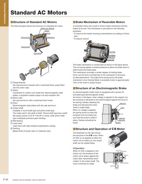
■Brake Mechanism of Reversible <strong>Motor</strong>s<br />
A reversible motor has a built-in friction brake mechanism (friction<br />
brake) at its rear. This mechanism is provided for the following<br />
purposes:<br />
· To improve the instant reversing characteristics by adding a friction<br />
load<br />
· To reduce overrun<br />
C U.S<br />
5Output Shaft<br />
7Lead Wires<br />
End Plate<br />
Coil Spring<br />
Brake Shoe<br />
Brake Plate<br />
1 Flange Bracket<br />
Die cast aluminum bracket with a machined finish, press-fitted<br />
into the motor case<br />
2 Stator<br />
Comprised of a stator core made from electromagnetic steel<br />
plates, a polyester-coated copper coil and insulation film<br />
3 <strong>Motor</strong> case<br />
Die cast aluminum with a machined finish inside<br />
4 Rotor<br />
Electromagnetic steel plates with die cast aluminum<br />
5 Output shaft<br />
Available in round shaft type and pinion shaft type.<br />
The metal used in the shaft is S45C. Round shaft type has a shaft<br />
flat (output power of 25 W 1/30 HP or more), while pinion shaft<br />
type undergoes precision gear finishing.<br />
6 Ball bearing<br />
7 Lead wires<br />
Lead wires with heat-resistant polyethylene coating<br />
8 Painting<br />
Baked finish of acrylic resin or melamine resin<br />
The brake mechanism is constructed as shown in the figure above.<br />
The coil spring applies constant pressure to allow the brake shoe to<br />
slide toward the brake plate.<br />
This mechanism provides a certain degree of holding brake<br />
force, but the force is limited due to the mechanism's structure,<br />
as described above. The brake force produced by the brake<br />
mechanism of an <strong>Oriental</strong> <strong>Motor</strong>'s reversible motor is approximately<br />
10% of the motor's output torque.<br />
■Structure of an Electromagnetic Brake<br />
An electromagnetic brake motor is equipped with a power off<br />
activated type electromagnetic brake.<br />
As shown in the figure, when voltage is applied to the magnet coil,<br />
the armature is attracted to the electromagnet against the force of<br />
the spring, thereby releasing the<br />
Magnet Coil<br />
brake and allowing the motor<br />
shaft to rotate freely.<br />
Spring<br />
When no voltage is applied,<br />
the spring works to press the<br />
armature onto the brake hub<br />
and hold the motor's shaft in<br />
Brake Hub<br />
place, thereby actuating the<br />
Brake Lining<br />
brake.<br />
Armature<br />
■Structure and Operation of<br />
The illustration to the right shows<br />
the structure of the C·B motor. When<br />
24 VDC is not applied to either the<br />
clutch coil or brake coil, the output<br />
shaft can be rotated freely.<br />
C·B <strong>Motor</strong><br />
●Operation<br />
When 24 VDC is applied to the<br />
clutch coil, the armature of the<br />
clutch coil is drawn against the<br />
clutch disk, transmitting motor<br />
rotation to the output shaft. The<br />
motor continues to rotate.<br />
<strong>Motor</strong><br />
Clutch Disk<br />
Armature<br />
Rotation<br />
Blue Blue Clutch and Brake<br />
Clutch ON<br />
24 VDC<br />
F-34 ORIENTAL MOTOR GENERAL CATALOG 2009/2010
●Stopping and Load Holding<br />
By removing the clutch coil excitation, after a certain time lag,<br />
applying 24 VDC to the brake coil will cause the armature on the<br />
brake to come into contact with the brake disk, which will cause the<br />
output shaft to come to a stop. During braking, the output shaft is<br />
released from the motor, so the inertia from the motor has no effect.<br />
The motor is constantly rotating.<br />
<strong>Motor</strong><br />
Armature<br />
Clutch and Brake<br />
Brake Disk<br />
Orange<br />
Stop<br />
Orange<br />
Brake ON<br />
24 VDC<br />
The figure below shows the relationship between the action of the<br />
motor shaft and output shaft and the state of excitation of the clutch<br />
and brake coils.<br />
Clutch<br />
Brake<br />
Speed<br />
ON<br />
OFF<br />
ON<br />
OFF<br />
Time Lag<br />
t1<br />
Actual Engaging Time<br />
t2<br />
Time Lag<br />
<strong>Motor</strong> Shaft<br />
t4<br />
t5<br />
Output<br />
Shaft<br />
t3<br />
t2<br />
t1<br />
t6<br />
t7<br />
Armature Attraction Time<br />
<strong>Motor</strong> Shaft<br />
Actual Braking Time<br />
Braking Time<br />
Acceleration Time after Engaging<br />
Engaging and Starting Time<br />
●Operation<br />
When operation is shifted from holding the load to moving the load,<br />
a time lag of 20 ms or more is required after releasing the brake and<br />
before applying voltage to the clutch. (This is to prevent the clutch<br />
and brake from engaging at the same time.)<br />
The time required for the clutch/brake output shaft to reach a<br />
constant speed after applying voltage to the clutch is referred to as<br />
the engaging and starting time (t5) and is calculated by adding up the<br />
following time elements:<br />
1 Armature Attraction Time t2<br />
The time required for the armature to come into contact with the<br />
clutch after voltage application to the clutch.<br />
2 Actual Engaging Time t4<br />
The time required for the clutch/brake output shaft, which is<br />
accelerated by dynamic friction torque, to engage completely<br />
with the motor shaft after the armature comes in contact with the<br />
clutch.<br />
3 Acceleration Time after Engaging t3<br />
The time needed to accelerate to the required speed when load<br />
is suddenly applied to the motor during actual engaging time<br />
described in 2, causing a temporary drop in speed.<br />
●Braking<br />
When operation is shifted from rotation to stopping or holding a load,<br />
a time lag of 20 ms or more is required after releasing the clutch<br />
and before applying voltage to the brake. The time required for the<br />
clutch/brake output shaft to come to a stop after applying voltage to<br />
the brake is referred to as the braking time (t7) and is calculated by<br />
adding up the following time elements:<br />
1 Armature Attraction Time t2<br />
The time required for the armature to contact with the brake plate<br />
after voltage application to the brake.<br />
2 Actual Braking Time t6<br />
The time required for rotation of the clutch/brake output shaft to<br />
come to a stop after the armature comes into contact with the<br />
brake plate.<br />
● Engaging and Starting Characteristics (<strong>Reference</strong> value)<br />
Engaging and Starting Time [msec] t5<br />
80<br />
70<br />
60<br />
50<br />
40<br />
30<br />
0<br />
0<br />
0.25<br />
CBI590-801WU<br />
60 Hz, 110 VAC, 115 VAC<br />
Friction Torque = 0<br />
1.0 2.0 3.0 4.0 5.0<br />
● Braking Characteristics (<strong>Reference</strong> value)<br />
Overrun [rotation]<br />
1.0<br />
0.9<br />
0.8<br />
0.7<br />
0.6<br />
0.5<br />
0<br />
Braking Time [msec] t7<br />
50<br />
40<br />
30<br />
20<br />
10<br />
0<br />
0.5 0.75 1.0 Load Inertia [×10 −4 kg·m 2]<br />
CBI590-801WU<br />
60 Hz, 110 VAC, 115 VAC<br />
Friction Torque = 0<br />
0.25 0.5 0.75<br />
0 1.0 2.0 3.0 4.0<br />
5.0<br />
Load Inertia [oz-in 2]<br />
1.0 Load Inertia [×10 −4 kg·m 2]<br />
Load Inertia [oz-in 2]<br />
Technical <strong>Reference</strong><br />
Selection<br />
Calculations Service Life<br />
Standard<br />
AC <strong>Motor</strong>s<br />
Speed<br />
Control<br />
Systems<br />
Stepping<br />
<strong>Motor</strong>s Gearheads<br />
Linear<br />
Heads<br />
Linear and<br />
Rotary<br />
Actuators Cooling Fans<br />
F-35
Technical <strong>Reference</strong><br />
■Speed – Torque Characteristics of<br />
Induction <strong>Motor</strong>s<br />
The figure below shows the speed – torque characteristics of<br />
induction motors.<br />
Torque<br />
TM<br />
Unstable<br />
Region<br />
M<br />
Stable<br />
Region<br />
■Speed – Torque Characteristics of<br />
Reversible <strong>Motor</strong>s<br />
The reversible motor is a capacitor run, single-phase induction<br />
motor that features the same speed – torque characteristics as an<br />
induction motor, as described above. However, the reversible motor<br />
features a higher starting torque than an induction motor in order to<br />
improve the instant reversing characteristics.<br />
Torque<br />
Reversible <strong>Motor</strong><br />
TS<br />
TP<br />
R<br />
P<br />
Induction <strong>Motor</strong><br />
Speed<br />
Under no load, the motor rotates at a speed close to synchronous<br />
speed. As the load increases, the motor's speed drops to a level (P)<br />
where a balance is achieved between load and motor torque (Tp).<br />
If the load is further increased and reaches point M, the motor can<br />
generate no greater torque and stops at point R.<br />
In other words, the motor can be operated in a stable range between<br />
M and O, while the range between R and M is subject to instability.<br />
Induction motors are available in two types: single-phase (capacitor<br />
run) and three-phase induction motors. With the single-phase motor,<br />
the starting torque is generally smaller than the operating torque,<br />
while the three-phase motor features a relatively greater starting<br />
torque.<br />
Torque<br />
Torque<br />
O<br />
Speed<br />
■Speed – Torque Characteristics of<br />
Torque <strong>Motor</strong>s<br />
The figure below shows the speed – torque characteristics of torque<br />
motors.<br />
The speed – torque characteristics of torque motors differ from those<br />
of induction motors or reversible motors. As the graph shows, they<br />
have sloping characteristics (torque is highest at zero speed and<br />
decreases steadily with increasing speed), enabling stable operation<br />
over a wide speed range, from starting to no load speed. The torque<br />
generated during reversal of the motor is a large positive torque in<br />
the same direction as the rotational magnetic field. When the motor<br />
which rotates uni-directionally is locked by the load and the motor<br />
is rotated opposite the desired direction, this torque acts as a force<br />
(braking force) to inhibit the motor from rotating backwards.<br />
Torque<br />
Stable Region<br />
Braking Region<br />
Stable Region<br />
of Induction<br />
<strong>Motor</strong><br />
Speed<br />
Single-Phase Induction <strong>Motor</strong>s<br />
Speed<br />
Three-Phase Induction <strong>Motor</strong>s<br />
Torque <strong>Motor</strong><br />
The torque the motor produces changes proportionally to roughly<br />
twice the power supply voltage.<br />
For example, if 110 V is applied to a motor whose rated voltage is<br />
100 V, the torque produced by the motor increases to approximately<br />
120%. In this case, the motor temperature will rise and may exceed<br />
the permissible range.<br />
If 90 V is applied to the same motor, the torque produced by the<br />
motor decreases to approximately 80%. In this case, the motor may<br />
not be able to operate the automated equipment as expected.<br />
For the above reasons, the power supply voltage should be kept<br />
within ±10% of the rated voltage. Otherwise, when the power<br />
supply voltage fluctuates beyond the aforementioned range, the<br />
motor temperature may rise beyond the permissible range or the<br />
motor torque may drop and thereby make the equipment operation<br />
unstable.<br />
−Ns<br />
Induction <strong>Motor</strong><br />
0<br />
Speed<br />
■Temperature Rise in Standard AC <strong>Motor</strong>s<br />
●Temperature Rise in <strong>Motor</strong>s<br />
When a motor is operating, all energy loss (copper loss, iron loss,<br />
etc.) of the motor is transformed into heat, causing the motor's<br />
temperature to rise.<br />
· Induction motors (continuous rating) reach the saturation point of<br />
temperature rise after two or three hours of operation, whereupon<br />
its temperature stabilizes.<br />
· Reversible motors (30 minutes rating) reach their limit for<br />
temperature rise after 30 minutes of operation. The temperature will<br />
increase further if operation continues.<br />
Ns<br />
F-36 ORIENTAL MOTOR GENERAL CATALOG 2009/2010
●Measuring the Temperature Rise<br />
The following is a description of the methods <strong>Oriental</strong> <strong>Motor</strong> uses<br />
for temperature measurement and for the determination of a motor's<br />
maximum permissible temperature rise.<br />
◇Thermometer Method<br />
The temperature at which the temperature rise during motor<br />
operation becomes saturated is measured using a thermometer<br />
or thermocouple attached to the center of the motor case. The<br />
temperature rise is defined as the difference between the ambient<br />
temperature and measured temperature.<br />
◇Resistance Change Method<br />
In the resistance change method, the winding temperature is<br />
measured according to the change in resistance value. A resistance<br />
meter and thermostat is used to measure the motor's winding<br />
resistance and ambient temperature before and after operation, from<br />
which the temperature rise in the motor windings is obtained.<br />
■Operating Time and Temperature Rise of<br />
Reversible <strong>Motor</strong>s<br />
Reversible motors have a "30 minute rating." However, the operating<br />
time varies according to the operating conditions, even with<br />
intermittent operation for short times. When using a reversible motor<br />
intermittently for a short period of time, a large current flows, which<br />
causes the generation of a large amount of heat when starting or<br />
reversing. However, as the natural cooling effect of the motor is high<br />
when the motor is left stopped for a longer period of time, you can<br />
curb rises in temperature.<br />
The motor case temperature equals the rise in motor temperature<br />
plus the ambient temperature. Generally, if the case temperature<br />
of the motor is 90˚C (194˚F) or less, continuous motor operation<br />
is possible with the same operating conditions, considering the<br />
insulation class of motor winding. However, the lower the motor<br />
temperature is, the longer the bearing grease life is.<br />
The motor temperature varies according to conditions such as the<br />
load, the operating cycle, the mounting method of the motor and the<br />
ambient temperature.<br />
■Overheat Protection Device<br />
If a motor operating in run mode locks due to overload, ambient<br />
temperature rises rapidly, or the input current increases for some<br />
reason, the motor's temperature rises abruptly. If the motor is left<br />
in this state, the performance of the insulation within the motor<br />
may deteriorate, reducing its life and, in extreme cases, scorching<br />
the winding and causing a fire. In order to protect the motor from<br />
such thermal abnormalities, our motors recognized by UL and CSA<br />
Standards and conform to EN and IEC Standards are equipped with<br />
the following overheat protection device.<br />
●Thermally Protected <strong>Motor</strong>s<br />
<strong>Motor</strong>s with a frame size of 70 mm (2.76 in.) sq., 80 mm (3.15 in.)<br />
sq., 90 mm (3.54 in.) sq., or 104 mm (4.09 in.) sq. contain a built-in<br />
automatic return type thermal protector. The structure of a thermal<br />
protector is shown in the figure below.<br />
Bimetal<br />
Lead Wires<br />
Solid-Silver Contact<br />
Structure of Thermal Protector<br />
The thermal protectors employ bimetal contacts, with solid silver<br />
used in the contacts. Solid silver has the lowest electrical resistance<br />
of all materials, along with a thermal conductivity second only to<br />
copper.<br />
◇Operating Temperature of Thermal Protector<br />
Open··· 130±5˚C (266±9˚F)<br />
[the operating temperature varies depending on the model,<br />
e.g., BH Series: 150±5˚C (302±9˚F)]<br />
Close··· 82±15˚C (179.6±27˚F)<br />
[the operating temperature varies depending on the model,<br />
e.g., BH Series: 96±15˚C (204.8±27˚F)]<br />
The motor winding temperature, where the thermal protector is<br />
activated, is slightly higher than the operating temperature listed<br />
above.<br />
●Impedance Protected <strong>Motor</strong>s<br />
<strong>Motor</strong>s with a frame size of 60 mm (2.36 in.) sq. or less are equipped<br />
with impedance protection.<br />
Impedance protected motors are designed with higher impedance<br />
in the motor windings so that even if the motor locks, the increase in<br />
current (input) will be minimized and temperature will not rise above<br />
a certain level.<br />
■Capacitor<br />
<strong>Oriental</strong> <strong>Motor</strong>'s single-phase AC motors are all permanent split<br />
capacitor types. Permanent split capacitor motors contain an<br />
auxiliary winding offset by 90 electrical degrees from the main<br />
winding. The capacitor is connected in series with the auxiliary<br />
winding, causing the advance of current phase in the auxiliary<br />
winding.<br />
<strong>Motor</strong>s employ vapor-deposition electrode capacitors recognized by<br />
UL. This type of capacitor, which uses a metallized paper or plastic<br />
film as an element, is also known as a "self-healing (SH) capacitor"<br />
because of the self-healing property of the capacitor element.<br />
Although most of the previous capacitors used paper elements, the<br />
plastic film capacitor has become a mainstream model in recent<br />
years due to the growing demand for compact design.<br />
●Capacitance<br />
The use of a capacitor with a different capacitance may cause<br />
excessive motor vibration and heat generation or may result in<br />
torque drops and unstable operation. Be sure to use the capacitor<br />
included with the motor. The capacitor's capacitance is expressed in<br />
microfarads (μF).<br />
●Rated Voltage<br />
Using a capacitor exceeding the rated voltage may cause damage<br />
and then smoke or ignite. Be sure to use the capacitor included with<br />
the motor. The rated voltage of the capacitor is expressed in volts<br />
(V). The capacitor’s rated voltage is indicated on the surface of the<br />
capacitor case. Take proper precautions, since the capacitor’s rated<br />
voltage is different from that of the motor.<br />
Technical <strong>Reference</strong><br />
Selection<br />
Calculations Service Life<br />
Standard<br />
AC <strong>Motor</strong>s<br />
Speed<br />
Control<br />
Systems<br />
Stepping<br />
<strong>Motor</strong>s Gearheads<br />
Linear<br />
Heads<br />
Linear and<br />
Rotary<br />
Actuators Cooling Fans<br />
F-37
Technical <strong>Reference</strong><br />
●Rated Conduction Time<br />
The rated conduction time is the minimum design life of the<br />
capacitor when operated at the rated load, rated voltage, rated<br />
temperature and rated frequency. The standard life expectancy is<br />
25000 hours. A capacitor that breaks at the end of its life expectancy<br />
may smoke or ignite. We recommend that the capacitor be replaced<br />
after the rated conduction time. Consider providing a separate<br />
protection measure to prevent the equipment from being negatively<br />
influenced in the event of capacitor failure.<br />
●Safety Feature of Capacitor<br />
Some capacitors are equipped with a safety feature that allows for<br />
safe and complete removal of the capacitor from circuits to prevent<br />
smoke and/or fire in the event of a dielectric breakdown. <strong>Oriental</strong><br />
<strong>Motor</strong> products use capacitors with UL recognized safety features<br />
that have passed the UL 810 requirement of the 10000 A fault<br />
current test.<br />
■Glossary<br />
●Ratings<br />
◇Ratings<br />
<strong>Motor</strong> rating represents the operation limit certified the motor on<br />
dynamic characteristics such as temperature, mechanical strength,<br />
vibration and efficiency, and there are two categories: continuous<br />
rating and limited duty rating. Operation limit on output power, as<br />
well as voltage, frequency and speed are established. These are<br />
known as rated output power, rated voltage, rated frequency and<br />
rated speed, respectively.<br />
◇Continuous and Limited Duty Ratings<br />
The time during which output can continue without abnormality is<br />
called a time rating. When continuous operation at rated output is<br />
possible, it is known as a continuous rating. When operation at rated<br />
output is possible only for a limited time, it is known as the limited<br />
duty rating.<br />
●Output Power<br />
◇Output Power<br />
The amount of work that can be performed in a given period of<br />
time is determined by the motor's speed and torque. Each motor<br />
specification indicates the value of rated output power. Output<br />
power is expressed in watts or in horsepower.<br />
Output Power [Watts] = 1.047 × 10 -1 × T × N<br />
1 HP = 746 Watts<br />
where: 1.047 × 10 -1 : Constant<br />
T [N·m] : Torque<br />
N [r/min] : Speed<br />
◇Rated Output Power<br />
This term refers to output power generated continuously when<br />
the optimal characteristics are achieved at the rated voltage and<br />
frequency in continuous operation. The speed and torque that<br />
produce the rated output power are called the rated speed and rated<br />
torque. Generally, the term "output power" refers to rated output<br />
power.<br />
●Torque<br />
◇Starting Torque<br />
This is the torque generated instantly when the motor starts. If the<br />
motor is subjected to a friction load greater than this torque, it will<br />
not operate. See 1 in the figure on the right.<br />
◇Stall Torque<br />
This is the maximum torque under which the motor will operate at<br />
a given voltage and frequency. If a load greater than this torque is<br />
applied to the motor, it will stall. See 2 in the figure below.<br />
◇Rated Torque<br />
This is the torque generated when the motor is continuously<br />
producing rated output power at the rated voltage and frequency. It<br />
is the torque at rated speed. See 3 in the figure below.<br />
◇Static Friction Torque<br />
Static friction torque is the torque output required to hold a load<br />
when the motor is stopped by an electromagnetic brake or similar<br />
device.<br />
◇Permissible Torque<br />
The permissible torque is the maximum torque that can be used<br />
when the motor is running. It is limited by the motor's rated torque,<br />
temperature rise and the strength of the gearhead combined with the<br />
motor.<br />
Speed – Torque Characteristics<br />
1: Starting torque<br />
2<br />
2: Stall torque<br />
3: Rated torque<br />
3<br />
4: Synchronous<br />
speed<br />
5: No load speed<br />
1<br />
6: Rated speed<br />
●Speed<br />
◇Synchronous Speed<br />
This is an intrinsic factor determined by line frequency and the<br />
number of poles.<br />
It is indicated as the speed per minute.<br />
Ns =<br />
120f<br />
P<br />
[r/min]<br />
NS : Synchronous speed [r/min]<br />
f : Frequency [Hz]<br />
P : Number of poles<br />
120 : Constant<br />
For example, for a four-pole motor with a line frequency of 60 Hz, the<br />
synchronous speed will be:<br />
Ns =<br />
120 × 60<br />
4<br />
Torque [N·m]<br />
= 1800 [r/min]<br />
See 4 in the figure above.<br />
6 5 4<br />
Speed [r/min]<br />
◇No Load Speed<br />
This is the speed under no load conditions.<br />
The speed of induction or reversible motors under no load<br />
conditions is lower than synchronous speed by a few percent<br />
(approximately 20 to 60 r/min). See 5 in the figure above.<br />
◇Rated Speed<br />
This is the appropriate speed of the motor at rated output power.<br />
From the standpoint of utility, it is the most desirable speed.<br />
See 6 in the figure above.<br />
F-38 ORIENTAL MOTOR GENERAL CATALOG 2009/2010
◇Slip<br />
The following formula is one method of expressing speed:<br />
Ns − N<br />
S = or N = Ns (1 − S)<br />
Ns<br />
NS : Synchronous speed [r/min]<br />
N : Speed under a given load [r/min]<br />
In the case of a four-pole, 60 Hz induction motor operated with a slip<br />
of S = 0.1, the speed under a given load will be:<br />
120 × 60<br />
N =<br />
(1 − 0.1) = 1800 (1 − 0.1) = 1620 [r/min]<br />
4<br />
●Overrun<br />
◇Overrun<br />
This is the number of excess rotations the motor makes from the<br />
instant the power is cut off to the time that it actually stops. It is<br />
normally indicated either by angle or by rotations.<br />
●Gearhead<br />
◇Gear Ratio<br />
The gear ratio is the ratio by which the gearhead reduces the motor<br />
1<br />
speed. The speed at the gearhead's output shaft is Gear Ratio times the<br />
motor speed.<br />
◇Maximum Permissible Torque<br />
This is the maximum load torque that can be applied to the<br />
gearhead.<br />
It is dependent upon such mechanical strength factors as the<br />
materials of gearheads and bearings, and size. Therefore, it varies<br />
according to the gearhead type and gear ratio.<br />
◇Service Factor<br />
This is a coefficient used to estimate the gearhead life.<br />
These values are determined in accordance with the results of life<br />
tests under various loads and conditions of use.<br />
◇Transmission Efficiency<br />
This is the efficiency when the torque is transmitted with the<br />
gearhead combined.<br />
It is expressed as a percentage (%) and is determined by the friction<br />
in the gears and bearings used in the gearhead and the resistance of<br />
the lubrication grease.<br />
Transmission efficiency is, when using a GN gearhead, usually<br />
90% for one stage of reduction gears, and is 81% for two stage<br />
gearheads. As the gear ratio increases, the number of reduction gear<br />
stages increases, with a consequent reduction in the gear efficiency<br />
to 73% and 66% for each gear stage added.<br />
◇Overhung Load<br />
This is a load on the gearhead output shaft in the vertical direction.<br />
The maximum overhung load on a gearhead shaft is called the<br />
permissible overhung load, and it varies with the gearhead type and<br />
distance from the shaft end.<br />
This is equivalent to tension under belt drive.<br />
◇Thrust Load<br />
This is the load that is placed in the direction of the gearhead output<br />
shaft.<br />
The maximum thrust load on the gearhead is called the permissible<br />
thrust load, which varies with the gearhead type.<br />
Gearhead<br />
Overhung Load<br />
Thrust Load<br />
●Others<br />
◇CW, CCW<br />
These show the direction of motor rotation.<br />
CW is clockwise as seen from the output shaft, while CCW is<br />
counterclockwise.<br />
Technical <strong>Reference</strong><br />
Selection<br />
Calculations Service Life<br />
Standard<br />
AC <strong>Motor</strong>s<br />
Speed<br />
Control<br />
Systems<br />
Stepping<br />
<strong>Motor</strong>s Gearheads<br />
Linear<br />
Heads<br />
Linear and<br />
Rotary<br />
Actuators Cooling Fans<br />
F-39
U<br />
Technical <strong>Reference</strong><br />
Speed Control Systems<br />
■Brushless <strong>Motor</strong> Structure and Principle<br />
of Operation<br />
●Structure of Brushless <strong>Motor</strong><br />
Ball Bearing<br />
Output Shaft<br />
Rotor<br />
Hall Effect IC<br />
Stator<br />
The brushless motor has a built-in magnetic element or optical<br />
encoder for the detection of rotor position. The position sensors<br />
send signals to the drive circuit. The brushless motor uses threephase<br />
windings in a "star" connection. A permanent magnet is used<br />
in the rotor.<br />
Structure of Brushless <strong>Motor</strong><br />
U = Phase-U Winding Stator<br />
V = Phase-V Winding<br />
W = Phase-W Winding<br />
Rotor = Magnet<br />
W<br />
V<br />
S<br />
N<br />
U<br />
N<br />
S<br />
V<br />
W<br />
Switching Sequences of Individual Transistors<br />
Step<br />
Transistor<br />
1 2 3 4 5 6 7 8 9 10 11 12 13<br />
Tr1 ON ON ON ON ON<br />
Tr2 ON ON ON ON<br />
Tr3 ON ON ON ON<br />
Tr4 ON ON ON ON<br />
Tr5 ON ON ON ON<br />
Tr6 ON ON ON ON ON<br />
Phase-U N − S S − N N − S S − N N<br />
Phase-V − N N − S S − N N − S S −<br />
Phase-W S S − N N − S S − N N − S<br />
●Control Method of Brushless <strong>Motor</strong>s<br />
The drive circuit of the brushless motor is connected in the<br />
configuration shown in the figure below, and is comprised of five<br />
main blocks.<br />
· Power circuit<br />
· Current control circuit<br />
· Logic circuit<br />
· Setting comparison circuit<br />
· Power supply circuit<br />
M<br />
Brushless<br />
<strong>Motor</strong><br />
Power Circuit<br />
Current Control<br />
Circuit<br />
Power Supply<br />
Circuit<br />
Rotor<br />
U<br />
Logic Circuit<br />
Setting Comparison<br />
Circuit<br />
<strong>Motor</strong> Winding<br />
H.E H.E H.E<br />
Hall Effect IC<br />
V<br />
W<br />
+<br />
Output 1<br />
Output 2<br />
Output 3<br />
A Hall effect IC is used for the sensor's magnetic element. Three Hall<br />
effect ICs are placed within the stator, and send digital signals as the<br />
motor rotates.<br />
●Drive Method of Brushless <strong>Motor</strong>s<br />
The motor windings are connected to switching transistors, six of<br />
which make up the inverter. The top and bottom transistors turn<br />
on and off, according to a predetermined sequence, to change<br />
the direction of current flow in the windings. The mechanism of<br />
brushless motor rotation can be described as follows:<br />
In step 1 of the transistor's switching sequence, as shown in the<br />
following figure, transistors Tr1 and Tr6 are in the "ON" state.<br />
At this time the winding current flows from phase U to phase W, and<br />
phases U and W are excited so that they become N and S poles,<br />
respectively, thus causing the rotor to turn 30˚. Repeating such a<br />
motion 12 times thereby facilitates rotation of the motor.<br />
<strong>Motor</strong> Winding<br />
1<br />
2<br />
3<br />
U<br />
V<br />
W<br />
Tr1<br />
Tr4<br />
−<br />
Power Circuit<br />
Tr2<br />
Tr5<br />
Tr3<br />
Tr6<br />
+<br />
−<br />
Start/Stop<br />
Brake/Run<br />
CW/CCW<br />
Speed Setting<br />
◇Power Circuit<br />
This circuit uses six transistors to control the current flow in the<br />
motor windings.<br />
The transistors provided at the top and bottom turn on and off<br />
repeatedly according to a predetermined sequence, thereby<br />
controlling the current flow to the motor windings.<br />
◇Current Control Circuit<br />
The current flow to the motor varies according to the load. It is<br />
constantly detected and controlled so that the speed will not deviate<br />
from the set speed.<br />
◇Logic Circuit<br />
The logic circuit detects the rotor position by receiving feedback<br />
signals from the motor's Hall effect IC and determines the excitation<br />
sequence of motor windings. The circuit signal is connected to each<br />
transistor base in the power circuit, driving the transistors according<br />
to a predetermined sequence. It also detects the motor's speed.<br />
The logic circuit is also used to control commands to the motor,<br />
including start/stop, brake/run and CW/CCW.<br />
◇Setting Comparison Circuit<br />
This circuit compares the motor speed signal against the speed<br />
setting signal in order to determine whether the motor speed is<br />
higher or lower than the set speed. The input to the motor is lowered<br />
if the motor speed is higher than the set speed, but the input is<br />
raised if it is lower than the set speed. In this manner, the speed that<br />
has varied is returned to the set speed.<br />
◇Power Supply Circuit<br />
This circuit converts a commercial power supply into the voltage<br />
necessary to drive the motor and control circuits.<br />
F-40 ORIENTAL MOTOR GENERAL CATALOG 2009/2010
■Speed Control Methods of AC <strong>Motor</strong><br />
Systems<br />
The basic block diagrams and outline of the control methods are<br />
shown below. AC speed control motors employ a closed-loop<br />
control system, while inverters employ an open-loop control system.<br />
●Inverters<br />
◇BHF<br />
Series, FE100/FE200<br />
Control Method<br />
1 Input from the AC power supply is rectified, and output as DC<br />
voltage.<br />
2 A voltage signal led by the frequency set with the volume for<br />
setting frequency is output.<br />
3 Voltage of the set frequency is applied to the motor.<br />
<strong>Motor</strong><br />
3<br />
Inverter<br />
1<br />
Converter<br />
Power Supply<br />
●AC Speed Control <strong>Motor</strong>s<br />
2<br />
Inverter<br />
Volume for Setting Frequency<br />
MIN<br />
MAX<br />
Voltage/Frequency Control Circuit<br />
◇ ES01/ES02, US Series<br />
Control Method<br />
1 The speed setting voltage is supplied via a speed potentiometer.<br />
2 The motor speed is detected and the speed signal voltage is<br />
supplied.<br />
3 The difference between the speed setting voltage and speed<br />
signal voltage is output.<br />
4 A voltage determined by the output from the comparator is<br />
supplied to the motor so that it will reach the set speed.<br />
<strong>Motor</strong><br />
Tachogenerator<br />
■Speed – Torque Characteristics of Speed<br />
Control Systems<br />
●Brushless <strong>Motor</strong> Systems<br />
The figure below illustrates the characteristics example of a BLF<br />
Series motor. The BX Series, BLU Series and BLH Series motors<br />
also have similar characteristics, although their speed control ranges<br />
are different.<br />
Brushless motors generate constant rated torque from 80 to<br />
4000 r/min, with the same starting torque as rated torque. (With<br />
the BLF Series and BLH Series, the output torque at the maximum<br />
speed is less than rated torque.) Unlike AC speed control motors,<br />
torque in a brushless motor will not drop at low speeds, so brushless<br />
motors can be used at rated torque from high to low speeds.<br />
In addition to continuous duty region, brushless motors also have<br />
limited duty region. The torque generated in the limited duty region,<br />
which is 1.2 times the rated torque (2 times for the BX Series and<br />
BLF Series), is effective for starting inertial load. If operated for<br />
more than approximately five seconds in the limited duty region, the<br />
overload protective function of the driver may engage and the motor<br />
will coast to a stop.<br />
Torque<br />
Speed - Torque Characteristics<br />
[oz-in]<br />
56<br />
28<br />
21<br />
0<br />
[N·m]<br />
0.4<br />
0.2<br />
0.15<br />
0<br />
80<br />
Starting Torque<br />
Limited Duty Region<br />
Continuous Duty Region<br />
1000 2000 3000<br />
Speed [r/min]<br />
BLF460A-□<br />
BLF460A-□FR<br />
BLF460A-A<br />
Rated Torque<br />
4000<br />
●Inverters<br />
The speed – torque characteristics shown in the figure below is<br />
typical for all inverters.<br />
The speed of an inverter varies depend on the frequency of the<br />
voltage applied to the motor. Accordingly, the speed also changes<br />
due to the load torque, which is equal to the induction motor.<br />
Speed - Torque Characteristics FE100C/5IK40GN (A)-SW2<br />
Technical <strong>Reference</strong><br />
Selection<br />
Calculations Service Life<br />
Standard<br />
AC <strong>Motor</strong>s<br />
Speed<br />
Control<br />
Systems<br />
Stepping<br />
<strong>Motor</strong>s Gearheads<br />
Linear<br />
Heads<br />
Linear and<br />
Rotary<br />
Actuators Cooling Fans<br />
Capacitor<br />
4<br />
2<br />
[oz-in]<br />
50<br />
[N·m]<br />
0.4<br />
Voltage-Control Circuit<br />
3<br />
Comparator<br />
Speed Controller<br />
1<br />
Speed Potentiometer<br />
Torque<br />
40<br />
30<br />
20<br />
10<br />
0<br />
0.3<br />
0.2<br />
0.1<br />
0<br />
0<br />
500 1000 1500<br />
Speed [r/min]<br />
Permissible Torque<br />
2000 2500<br />
Power Supply<br />
0<br />
10 20 30 40 50 60 70 80<br />
Set Frequency [Hz]<br />
F-41
Technical <strong>Reference</strong><br />
●AC Speed Control <strong>Motor</strong>s<br />
The speed – torque characteristics shown in the figure below is<br />
typical for all AC speed control motors.<br />
Speed - Torque Characteristics ES01/5IK40RGN (A)-AW2U<br />
Torque [oz-in]<br />
70<br />
60<br />
50<br />
40<br />
30<br />
20<br />
10<br />
0<br />
Torque [N·m]<br />
0.5<br />
0.4<br />
0.3<br />
0.2<br />
0.1<br />
Permissible Torque when<br />
Gearhead is Attached<br />
115 VAC Safe-Operation Line<br />
0<br />
0 500 1000 1500 1800<br />
Speed [r/min]<br />
Torque [lb-in]<br />
Speed – Torque Characteristics<br />
US590-501U2/5GU5KA<br />
40<br />
30<br />
20<br />
10<br />
0<br />
Torque [N·m]<br />
4.0<br />
3.0<br />
2.0<br />
1.0<br />
0<br />
0<br />
US590-501U2+5GU5KA<br />
BLU590A-5<br />
Load Factor 50%<br />
Approx. 2:1<br />
Load Factor 20% Approx. 20:1<br />
100 200 300 400<br />
Speed [r/min]<br />
●Safe-Operation Line and Permissible Torque When<br />
Gearhead is Attached<br />
Input power to the speed control motor varies with the load and<br />
speed. The greater the load, and the lower the speed, the greater an<br />
increase in motor temperature.<br />
In the speed – torque characteristics of AC speed control motor and<br />
inverter, there is the safe-operation line, while the area below the line<br />
is called the continuous duty region.<br />
The safe-operation line, measured by motor's temperature, indicates<br />
its limit for continuous operation (30 minutes operation for a<br />
reversible motor) with the temperature level below the permissible<br />
maximum.<br />
Whether the motor can be operated at a specific load and speed<br />
is determined by measuring the temperature of the motor case. In<br />
general, when the motor case temperature is 90˚C (194˚F) or less,<br />
continuous operation is possible, considering the insulation class<br />
of motor winding. It is recommended that the motor be used under<br />
conditions that keep the motor temperature low, since the motor life<br />
is extended with lower motor temperature.<br />
When using a gearhead, be aware that it is necessary to operate<br />
below the torque in the "gearmotor – torque table." If the actual<br />
torque required exceeds this torque, it may damage the gearhead<br />
and shorten its life.<br />
●Variable Speed Range (Speed ratio) and Load Factor<br />
When the ratio of minimum speed and maximum speed of an AC<br />
speed control motor is given as the motor's speed ratio, the speed<br />
ratio increases to as much as 20:1 in a range where the load factor<br />
(ratio of load torque to starting torque) is small (Refer to the 20%<br />
load factor range in the diagram to the right). This widens the<br />
motor's range of operation.<br />
If the load factor is high, the speed ratio becomes low.<br />
◇Load Factor and Speed Ratio<br />
The following explains the relationship of load factor and speed ratio.<br />
Usually, a motor is often used in combination with a gearhead. The<br />
following assumes such a configuration.<br />
The following table shows the continuous duty region and speed<br />
ratio of the US Series at load factors of 20% and 50%, as read from<br />
the diagram.<br />
Although the speed ratio is large when the load factor is 20%, it<br />
decreases when the load factor is 50%. As shown, generally AC<br />
speed control motors do not have a wide speed range. To operate<br />
your motor over a wide speed range, choose a type that offers high<br />
starting torque (a motor with the next larger frame size).<br />
With a brushless motor, the operation speed range remains wide<br />
regardless of the load factor, as indicated by the dotted line.<br />
Load Factor<br />
[%]<br />
Min. Speed<br />
[r/min]<br />
Continuous Duty Region<br />
Max. Speed<br />
[r/min]<br />
Speed Ratio<br />
20 17 348 Approx. 20:1<br />
50 148 337 Approx. 2:1<br />
◇Speed Ratio When a High Ratio Gearhead is Used<br />
Since the starting torque is also limited by the maximum permissible<br />
torque of the gearhead, the load factor of a gearhead with a high<br />
gear ratio is determined by the load torque with respect to the<br />
maximum permissible torque of the gearhead.<br />
In the previous example, a gearhead with a gear ratio of 5:1 was<br />
used. The diagram below shows when a gearhead with a gear ratio<br />
of 100:1 is used.<br />
Torque [lb-in]<br />
Speed – Torque Characteristics with a High Gear Ratio<br />
400<br />
300<br />
200<br />
100<br />
0<br />
Torque [N·m]<br />
40<br />
30<br />
20<br />
10<br />
0<br />
0<br />
US590-501U2+5GU100KA<br />
BLU590A-100<br />
1:20<br />
Load Factor 50% Approx. 19:1<br />
Load Factor 30% Approx. 20:1<br />
5 10 15 20<br />
Speed [r/min]<br />
The maximum permissible torque of the 5GU100KA, which has a<br />
gear ratio of 100:1, is 20 N·m (177 lb-in). The speed ratios at load<br />
factors of 30% and 50% are shown in the table below:<br />
Load Factor<br />
[%]<br />
Min. Speed<br />
[r/min]<br />
Continuous Duty Region<br />
Max. Speed<br />
[r/min]<br />
Speed Ratio<br />
30 0.9 17.6 Approx. 20:1<br />
50 0.9 17.4 Approx. 19:1<br />
The table above demonstrates that high speed ratios can be<br />
obtained by combining a motor with a gearhead having a high gear<br />
ratio, in which case the load factor is one of minor concern.<br />
F-42 ORIENTAL MOTOR GENERAL CATALOG 2009/2010
■Load Torque – Driver Input Current Characteristics of Brushless <strong>Motor</strong>s (<strong>Reference</strong> values)<br />
The driver input current for brushless motors varies with the load torque. Load torque is roughly proportional to the driver input current. These<br />
characteristics may be used to estimate load torque from the driver input current. However, this is valid only when the motor is rotating at a<br />
steady speed. Starting and bi-directional rotation requires greater current input, so the characteristics do not apply to such operations.<br />
●Data for combination types models and geared motors apply to the motor only.<br />
◇ BX Series<br />
BX230A-□S, BX230AM-□S<br />
BX230A-□FR, BX230AM-□FR<br />
BX230A-A, BX230AM-A<br />
Driver Input Current [A]<br />
1.5<br />
1.0<br />
0.5<br />
0<br />
0<br />
0<br />
3000 r/min<br />
2000 r/min<br />
1000 r/min<br />
300 r/min<br />
30 r/min<br />
Rated Torque<br />
0.02 0.04 0.06 0.08 0.10 0.12 [N . m]<br />
2 4 6 8 10 12 14 16 [oz-in]<br />
Load Torque<br />
BX460A-□S, BX460AM-□S<br />
BX460A-□FR, BX460AM-□FR<br />
BX460A-A, BX460AM-A<br />
Driver Input Current [A]<br />
2.0<br />
1.5<br />
1.0<br />
0.5<br />
0<br />
0<br />
0<br />
3000 r/min<br />
2000 r/min<br />
1000 r/min<br />
300 r/min<br />
30 r/min<br />
Rated Torque<br />
0.05 0.1 0.15 0.2 0.25 [N . m]<br />
5 10 15 20 25 30 35 [oz-in]<br />
Load Torque<br />
0.1<br />
BX5120A-□S, BX5120AM-□S<br />
BX5120A-□FR, BX5120AM-□FR<br />
BX5120A-A, BX5120AM-A<br />
4.0<br />
3000 r/min<br />
2000 r/min<br />
3.0<br />
1000 r/min<br />
2.0<br />
1.0<br />
300 r/min<br />
30 r/min<br />
Rated Torque<br />
0<br />
0 0.2 0.3 0.4 0.5 [N.m]<br />
0 10 20 30 40 50 60 70 [oz-in]<br />
Load Torque<br />
Driver Input Current [A]<br />
BX230C-□S, BX230CM-□S (Single-phase 200-230 VAC)<br />
BX230C-□FR, BX230CM-□FR (Single-phase 200-230 VAC)<br />
BX230C-A, BX230CM-A (Single-phase 200-230 VAC)<br />
Driver Input Current [A]<br />
0.8<br />
0.6<br />
0.4<br />
0.2<br />
0<br />
0<br />
0<br />
3000 r/min<br />
2000 r/min<br />
1000 r/min<br />
300 r/min<br />
30 r/min<br />
Rated Torque<br />
0.02 0.04 0.06 0.08 0.10 0.12[N . m]<br />
2 4 6 8 10 12 14 16 [oz-in]<br />
Load Torque<br />
BX460C-□S, BX460CM-□S (Single-phase 200-230 VAC)<br />
BX460C-□FR, BX460CM-□FR (Single-phase 200-230 VAC)<br />
BX460C-A, BX460CM-A (Single-phase 200-230 VAC)<br />
Driver Input Current [A]<br />
1.25<br />
1.0<br />
0.75<br />
0.5<br />
0.25<br />
0<br />
0<br />
0<br />
3000 r/min<br />
2000 r/min<br />
1000 r/min<br />
300 r/min<br />
30 r/min<br />
Rated Torque<br />
0.05 0.1 0.15 0.2 0.25 [N . m]<br />
5 10 15 20 25 30 35[oz-in]<br />
Load Torque<br />
BX5120C-□S, BX5120CM-□S (Single-phase 200-230 VAC)<br />
BX5120C-□FR, BX5120CM-□FR (Single-phase 200-230 VAC)<br />
BX5120C-A, BX5120CM-A (Single-phase 200-230 VAC)<br />
2.0<br />
3000 r/min<br />
2000 r/min<br />
1.5<br />
1000 r/min<br />
1.0<br />
0.5<br />
300 r/min<br />
30 r/min<br />
Rated Torque<br />
0<br />
0 0.1 0.2 0.3 0.4 0.5 [N.m]<br />
0 10 20 30 40 50 60 70[oz-in]<br />
Load Torque<br />
Driver Input Current [A]<br />
BX230C-□S, BX230CM-□S (Three-phase 200-230 VAC)<br />
BX230C-□FR, BX230CM-□FR (Three-phase 200-230 VAC)<br />
BX230C-A, BX230CM-A (Three-phase 200-230 VAC)<br />
Driver Input Current [A]<br />
0.6<br />
0.4<br />
0.2<br />
0<br />
0<br />
0<br />
3000 r/min<br />
2000 r/min<br />
1000 r/min<br />
300 r/min<br />
30 r/min<br />
Rated Torque<br />
0.02 0.04 0.06 0.08 0.10 0.12[N . m]<br />
2 4 6 8 10 12 14 16 [oz-in]<br />
Load Torque<br />
BX460C-□S, BX460CM-□S (Three-phase 200-230 VAC)<br />
BX460C-□FR, BX460CM-□FR (Three-phase 200-230 VAC)<br />
BX460C-A, BX460CM-A (Three-phase 200-230 VAC)<br />
Driver Input Current [A]<br />
0.8<br />
0.6<br />
0.4<br />
0.2<br />
3000 r/min<br />
2000 r/min<br />
1000 r/min<br />
300 r/min<br />
30 r/min<br />
Rated Torque<br />
0<br />
0 0.05 0.1 0.15 0.2 0.25 [N . m]<br />
0 5 10 15 20 25 30 35 [oz-in]<br />
Load Torque<br />
BX5120C-□S, BX5120CM-□S (Three-phase 200-230 VAC)<br />
BX5120C-□FR, BX5120CM-□FR (Three-phase 200-230 VAC)<br />
BX5120C-A, BX5120CM-A (Three-phase 200-230 VAC)<br />
Driver Input Current [A]<br />
1.25<br />
1.0<br />
3000 r/min<br />
2000 r/min<br />
0.75<br />
0.5<br />
1000 r/min<br />
300 r/min<br />
30 r/min<br />
0.25<br />
0<br />
0 0.1 0.2 0.3 0.4<br />
Rated Torque<br />
0.5 [N .m]<br />
0 10 20 30 40 50 60 70 [oz-in]<br />
Load Torque<br />
Technical <strong>Reference</strong><br />
Selection<br />
Calculations Service Life<br />
Standard<br />
AC <strong>Motor</strong>s<br />
Speed<br />
Control<br />
Systems<br />
Stepping<br />
<strong>Motor</strong>s Gearheads<br />
Linear<br />
Heads<br />
Linear and<br />
Rotary<br />
Actuators Cooling Fans<br />
F-43
Technical <strong>Reference</strong><br />
BX6200A-□S, BX6200AM-□S<br />
BX6200A-A, BX6200AM-A<br />
3000 r/min<br />
5.0<br />
2000 r/min<br />
4.0<br />
1000 r/min<br />
3.0<br />
300 r/min<br />
2.0<br />
30 r/min<br />
1.0<br />
Rated Torque<br />
0 0 0.2 0.4 0.6 0.8 [N.m]<br />
0 20 40 60 80 100 [oz-in]<br />
Load Torque<br />
BX6400S-□S, BX6400SM-□S<br />
BX6400S-A, BX6400SM-A<br />
3000 r/min<br />
3.0<br />
2000 r/min<br />
Driver Input Current [A]<br />
Driver Input Current [A]<br />
2.0<br />
1.0<br />
◇ BLU Series<br />
BLU220A-□, BLU220A-□FR<br />
BLU220A-A<br />
1000 r/min<br />
300 r/min<br />
30 r/min<br />
Rated Torque<br />
0<br />
0 0.2 0.4 0.6 0.8 1.0 1.2 1.4[N.m]<br />
0 20 40 60 80 100 120 140160 180 [oz-in]<br />
Load Torque<br />
BX6200C-□S, BX6200CM-□S (Single-phase 200-230 VAC)<br />
BX6200C-A, BX6200CM-A (Single-phase 200-230 VAC)<br />
BX6200C-□S, BX6200CM-□S (Three-phase 200-230 VAC)<br />
BX6200C-A, BX6200CM-A (Three-phase 200-230 VAC)<br />
3.0<br />
3000 r/min<br />
2.0<br />
0 0 0.2 0.4 0.6 0.8 [N.m]<br />
0 0 0.2 0.4 0.6 0.8 [N.m]<br />
0 20 40 60 80 100 [oz-in]<br />
0 20 40 60 80 100 [oz-in]<br />
2000 r/min<br />
2000 r/min<br />
1.5<br />
2.0<br />
1000 r/min<br />
1000 r/min<br />
1.0<br />
1.0<br />
300 r/min<br />
30 r/min 0.5<br />
300 r/min<br />
30 r/min<br />
Rated Torque<br />
Rated Torque<br />
Load Torque<br />
Load Torque<br />
Driver Input Current [A]<br />
BLU220C-□, BLU220C-□FR<br />
BLU220C-A<br />
Driver Input Current [A]<br />
BLU220S-□, BLU220S-□FR<br />
BLU220S-A<br />
Driver Input Current [A]<br />
1.0<br />
2000 r/min<br />
0.75<br />
1500 r/min<br />
1000 r/min<br />
0.5<br />
500 r/min<br />
100 r/min<br />
0.25<br />
Rated Torque<br />
0<br />
0 0.02 0.04 0.06 0.08 0.1 [N.m]<br />
0 2 4 6 8 10 12 14 [oz-in]<br />
Load Torque<br />
BLU440A-□, BLU440A-□FR<br />
BLU440A-A<br />
Driver Input Current [A]<br />
1.5<br />
1.2<br />
0.9<br />
0.6<br />
0.3<br />
0<br />
0<br />
0.05 0.1 0.15 0.2[N.m]<br />
[oz-in]<br />
0 5 10 15 20 25<br />
Load Torque<br />
BLU590A-□, BLU590A-□FR<br />
BLU590A-A<br />
Driver Input Current [A]<br />
2.4<br />
1.8<br />
1.2<br />
0.6<br />
2000 r/min<br />
1500 r/min<br />
1000 r/min<br />
500 r/min<br />
100 r/min<br />
Rated Torque<br />
2000 r/min<br />
1500 r/min<br />
1000 r/min<br />
500 r/min<br />
100 r/min<br />
Rated Torque<br />
0<br />
0<br />
0.15 0.3 0.45[N.m]<br />
0 20 40 60 [oz-in]<br />
Load Torque<br />
Driver Input Current [A]<br />
0.6<br />
2000 r/min<br />
0.45<br />
1500 r/min<br />
1000 r/min<br />
0.3<br />
500 r/min<br />
100 r/min<br />
0.15<br />
Rated Torque<br />
0<br />
0 0.02 0.04 0.06 0.08 0.1 [N.m]<br />
0 2 4 6 8 10 12 14 [oz-in]<br />
Load Torque<br />
BLU440C-□, BLU440C-□FR<br />
BLU440C-A<br />
Driver Input Current [A]<br />
1.2<br />
0.9<br />
0.6<br />
0.3<br />
0<br />
0<br />
0.05 0.1 0.15 0.2[N.m]<br />
[oz-in]<br />
0 5 10 15 20 25<br />
Load Torque<br />
BLU590C-□, BLU590C-□FR<br />
BLU590C-A<br />
Driver Input Current [A]<br />
1.2<br />
0.8<br />
0.4<br />
0<br />
0<br />
2000 r/min<br />
1500 r/min<br />
1000 r/min<br />
500 r/min<br />
100 r/min<br />
Rated Torque<br />
0.15 0.3 0.45 [N.m]<br />
[oz-in]<br />
0 20 40 60<br />
Load Torque<br />
2000 r/min<br />
1500 r/min<br />
1000 r/min<br />
500 r/min<br />
100 r/min<br />
Rated Torque<br />
Driver Input Current [A]<br />
0.4<br />
2000 r/min<br />
0.3<br />
1500 r/min<br />
1000 r/min<br />
0.2<br />
500 r/min<br />
100 r/min<br />
0.1<br />
Rated Torque<br />
0<br />
0 0.02 0.04 0.06 0.08 0.1 [N.m]<br />
0 2 4 6 8 10 12 14 [oz-in]<br />
Load Torque<br />
BLU440S-□, BLU440S-□FR<br />
BLU440S-A<br />
Driver Input Current [A]<br />
0.8<br />
0.6<br />
0.4<br />
0.2<br />
0<br />
0<br />
0.05 0.1 0.15 0.2[N.m]<br />
[oz-in]<br />
0 5 10 15 20 25<br />
Load Torque<br />
BLU590S-□, BLU590S-□FR<br />
BLU590S-A<br />
Driver Input Current [A]<br />
2000 r/min<br />
1500 r/min<br />
1000 r/min<br />
500 r/min<br />
100 r/min<br />
Rated Torque<br />
1.0<br />
2000 r/min<br />
0.8<br />
0.6<br />
1500 r/min<br />
1000 r/min<br />
0.4<br />
500 r/min<br />
100 r/min<br />
0.2<br />
Rated Torque<br />
0<br />
0 0.15 0.3 0.45 [N.m]<br />
0 20 40 60 [oz-in]<br />
Load Torque<br />
F-44 ORIENTAL MOTOR GENERAL CATALOG 2009/2010
◇ FBL Series<br />
FBL575AW-□<br />
FBL575AW-A<br />
2.0<br />
Driver Input Current [A]<br />
1.5<br />
1.0<br />
0.5<br />
0<br />
0<br />
0<br />
FBL5120AW-□<br />
FBL5120AW-A<br />
Driver Input Current [A]<br />
2.5<br />
3000 r/min<br />
2000 r/min<br />
1000 r/min<br />
300 r/min<br />
Rated Torque<br />
0.1 0.2<br />
[N.m]<br />
10 20 30 40 [oz-in]<br />
Load Torque<br />
3000 r/min<br />
2.0<br />
1.5<br />
1.0<br />
2000 r/min<br />
1000 r/min<br />
300 r/min<br />
0.5<br />
Rated Torque<br />
0<br />
0 0.1 0.2 0.3 0.4 [N.m]<br />
0 10 20 30 40 50 60 [oz-in]<br />
Load Torque<br />
◇ BLH Series<br />
BLH015K-□<br />
BLH015K-A<br />
Driver Input Current [A]<br />
1.5<br />
1.0<br />
0.5<br />
0<br />
0<br />
0<br />
0.01 0.02 0.03 0.04 0.05 [N . m]<br />
1 2 3 4 5 6 7[oz-in]<br />
Load Torque<br />
BLH5100KC-□, BLH5100KC-□FR<br />
BLH5100KC-A<br />
Driver Input Current [A]<br />
6.0<br />
5.0<br />
4.0<br />
3.0<br />
2.0<br />
1.0<br />
0<br />
0<br />
0<br />
3000 r/min<br />
0.1 0.2 0.3 0.4 [N . m]<br />
10 20 30 40 50 [oz-in]<br />
Load Torque<br />
3000 r/min<br />
2500 r/min<br />
2000 r/min<br />
1500 r/min<br />
1000 r/min<br />
500 r/min<br />
100 r/min<br />
Rated Torque<br />
2500 r/min<br />
2000 r/min<br />
1500 r/min<br />
1000 r/min<br />
500 r/min<br />
100 r/min<br />
Rated Torque<br />
FBL575CW-□<br />
FBL575CW-A<br />
Driver Input Current [A]<br />
1.5<br />
1.0<br />
0.5<br />
0<br />
0 0.1 0.2<br />
3000 r/min<br />
2000 r/min<br />
1000 r/min<br />
300 r/min<br />
Rated Torque<br />
[N.m]<br />
0 10 20 30 40 [oz-in]<br />
Load Torque<br />
FBL5120CW-□<br />
FBL5120CW-A<br />
Driver Input Current [A]<br />
2.0<br />
1.5<br />
1.0<br />
0.5<br />
0<br />
0<br />
0<br />
3000 r/min<br />
2000 r/min<br />
1000 r/min<br />
300 r/min<br />
Rated Torque<br />
0.1 0.2 0.3 0.4 [N.m]<br />
10 20 30 40 50 60 [oz-in]<br />
Load Torque<br />
BLH230KC-□, BLH230KC-□FR<br />
BLH230KC-A<br />
2500 r/min<br />
2.0<br />
2000 r/min<br />
1.5<br />
1.0<br />
3000 r/min<br />
1500 r/min<br />
1000 r/min<br />
500 r/min<br />
0.5<br />
0<br />
0 0.02 0.04 0.06 0.08 0.10<br />
100 r/min<br />
Rated Torque<br />
0.12 [N . m]<br />
0 2 4 6 8 10 12 14 16 [oz-in]<br />
Load Torque<br />
Driver Input Current [A]<br />
FBL575SW-□<br />
FBL575SW-A<br />
Driver Input Current [A]<br />
1.0<br />
0.75<br />
0.5<br />
0.25<br />
3000 r/min<br />
2000 r/min<br />
1000 r/min<br />
300 r/min<br />
Rated Torque<br />
0<br />
0 0.1 0.2<br />
[N·m]<br />
0 10 20 30 40 [oz-in]<br />
Load Torque<br />
FBL5120SW-□<br />
FBL5120SW-A<br />
Driver Input Current [A]<br />
1.5<br />
1.0<br />
0.5<br />
0<br />
0<br />
0<br />
3000 r/min<br />
2000 r/min<br />
1000 r/min<br />
300 r/min<br />
Rated Torque<br />
0.1 0.2 0.3 0.4 [N.m]<br />
10 20 30 40 50 60 [oz-in]<br />
Load Torque<br />
BLH450KC-□, BLH450KC-□FR<br />
BLH450KC-A<br />
4.0<br />
3.0<br />
2500 r/min<br />
2000 r/min<br />
3000 r/min<br />
2.0<br />
1500 r/min<br />
1000 r/min<br />
1.0<br />
500 r/min<br />
100 r/min<br />
0<br />
0 0.04 0.08 0.12 0.16<br />
Rated Torque<br />
0.2 [N . m]<br />
0 5 10 15 20 25 [oz-in]<br />
Load Torque<br />
Driver Input Current [A]<br />
Technical <strong>Reference</strong><br />
Selection<br />
Calculations Service Life<br />
Standard<br />
AC <strong>Motor</strong>s<br />
Speed<br />
Control<br />
Systems<br />
Stepping<br />
<strong>Motor</strong>s Gearheads<br />
Linear<br />
Heads<br />
Linear and<br />
Rotary<br />
Actuators Cooling Fans<br />
F-45
Technical <strong>Reference</strong><br />
Stepping <strong>Motor</strong>s<br />
■Structure of Stepping <strong>Motor</strong>s<br />
The figures below show two cross-sections of a 5-phase stepping<br />
motor.<br />
The stepping motor consists primarily of two parts: a stator and<br />
rotor.<br />
The rotor is made up of three components: rotor 1, rotor 2 and a<br />
permanent magnet. The rotor is magnetized in the axial direction so<br />
that, for example, if rotor 1 is polarized north, rotor 2 will be polarized<br />
south.<br />
Ball Bearing<br />
Rotor 1<br />
Permanent Magnet<br />
Rotor 2<br />
■Stepping <strong>Motor</strong>'s Principle of Operation<br />
Following is an explanation of the relationship between the<br />
magnetized stator small teeth and rotor small teeth.<br />
●When Phase "A" is Excited<br />
When phase A is excited, its poles are polarized south. This attracts<br />
the teeth of rotor 1, which are polarized north, while repelling the<br />
teeth of rotor 2, which are polarized south. Therefore, the forces on<br />
the entire unit in equilibrium hold the rotor stationary. At this time,<br />
the teeth of the phase B poles, which are not excited, are misaligned<br />
with the south-polarized teeth of rotor 2 so that they are offset 0.72˚.<br />
This summarizes the relationship between the stator teeth and rotor<br />
teeth with phase A excited.<br />
No Offset<br />
3.6°<br />
0.72°<br />
3.6°+0.72°<br />
N<br />
S<br />
N<br />
Stator<br />
N<br />
Phase A Phase B<br />
7.2°<br />
Shaft<br />
Stator<br />
Winding<br />
<strong>Motor</strong> Structural Diagram: Cross-Section Parallel to Shaft<br />
The stator has ten magnetic poles with small teeth, each pole being<br />
provided with a winding.<br />
Each winding is connected to the winding of the opposite pole so<br />
that both poles are magnetized in the same polarity when current is<br />
sent through the pair of windings. (Running a current through a given<br />
winding magnetizes the opposing pair of poles in the same polarity,<br />
i.e., north or south.)<br />
The opposing pair of poles constitutes one phase. Since there are<br />
five phases, A through E, the motor is called a "5-phase stepping<br />
motor."<br />
There are 50 small teeth on the outer perimeter of each rotor, with<br />
the small teeth of rotor 1 and rotor 2 being mechanically offset from<br />
each other by half a tooth pitch.<br />
Rotor 1<br />
N<br />
No Offset<br />
Phase C<br />
Phase D<br />
Current<br />
Phase E<br />
●When Phase "B" is Excited<br />
When excitation switches from phase A to B, the phase B poles are<br />
polarized north, attracting the south polarity of rotor 2 and repelling<br />
the north polarity of rotor 1.<br />
0.72°<br />
N<br />
N<br />
S<br />
S<br />
N<br />
3.6°<br />
S S<br />
N<br />
S<br />
Excitation: To send current through a motor winding<br />
Magnetic pole: A projected part of the stator, magnetized by excitation<br />
Small teeth: The teeth on the rotor and stator<br />
Phase A<br />
Shaft<br />
Stator<br />
Rotor<br />
Phase B<br />
Phase A<br />
Rotor 1<br />
N<br />
Phase B<br />
Stator<br />
Phase C<br />
Phase D<br />
N<br />
0.72°<br />
Phase C<br />
S<br />
S<br />
N<br />
Current<br />
Phase E<br />
3.6°<br />
S S<br />
Phase D<br />
N<br />
Phase E<br />
<strong>Motor</strong> Structural Diagram: Cross-Section Perpendicular to Shaft<br />
F-46 ORIENTAL MOTOR GENERAL CATALOG 2009/2010
In other words, when excitation switches from phase A to B, the<br />
rotor rotates by 0.72˚. As excitation shifts from phase A, to phases B,<br />
C, D and E, then back around to phase A, the stepping motor rotates<br />
precisely in 0.72˚ steps. To rotate in reverse, reverse the excitation<br />
sequence to phase A, E, D, C, B, then back around to phase A.<br />
High resolution of 0.72˚ is inherent in the mechanical offset between<br />
the stator and rotor, accounting for the achievement of precise<br />
positioning without the use of an encoder or other sensors. High<br />
stopping accuracy of ±3 arc minutes (with no load) is obtained,<br />
since the only factors affecting stopping accuracy are variations in<br />
the machining precision of the stator and rotor, assembly precision<br />
and DC resistance of windings. The driver performs the role of phase<br />
switching, and its timing is controlled by a pulse-signal input to<br />
the driver. The example above shows the excitation advancing one<br />
phase at a time, but in an actual stepping motor an effective use of<br />
the windings is made by exciting four or five phases simultaneously.<br />
■Basic Characteristics of Stepping <strong>Motor</strong>s<br />
An important point to consider in the application of stepping motors<br />
is whether the motor characteristics are suitable to the operating<br />
conditions.<br />
The following sections describe the characteristics to be considered<br />
in the application of stepping motors.<br />
The two main characteristics of stepping motor performance are:<br />
● Dynamic Characteristics:<br />
These are the starting and rotational characteristics of a stepping<br />
motor, mainly affecting the machinery’s movement and cycling<br />
time.<br />
● Static Characteristics:<br />
These are the characteristics relating to the changes in angle that<br />
take place when the stepping motor is in standstill mode, affecting<br />
the machinery’s level of precision.<br />
Torque<br />
1TH<br />
3<br />
fs<br />
●Dynamic Characteristics<br />
2<br />
Speed - Torque Characteristics<br />
Speed<br />
◇Speed – Torque Characteristics<br />
The figure above is a characteristics graph showing the relationship<br />
between the speed and torque of a driven stepping motor.<br />
These characteristics are always referred to in the selection of a<br />
stepping motor. The horizontal axis represents the speed at the<br />
motor output shaft, and the vertical axis represents the torque.<br />
The speed – torque characteristics are determined by the motor and<br />
driver, and are greatly affected by the type of driver being used.<br />
2 Pullout torque<br />
The pullout torque is the maximum torque that can be output at a<br />
given speed.<br />
When selecting a motor, be sure the required torque falls within<br />
this curve.<br />
3 Maximum starting frequency (fS)<br />
This is the maximum pulse speed at which the motor can start or<br />
stop instantly (without an acceleration/deceleration time) when the<br />
stepping motor’s friction load and inertial load are 0.<br />
Driving the motor at a pulse speed in excess of this rate will<br />
require a gradual acceleration or deceleration. This frequency will<br />
decrease when an inertial load is added to the motor.<br />
Refer to the inertial load – starting frequency characteristics<br />
below.<br />
Maximum response frequency (fr)<br />
This is the maximum pulse speed at which the motor can be<br />
operated through gradual acceleration or deceleration when the<br />
stepping motor’s friction load and inertial load are 0.<br />
The figure below shows the speed – torque characteristics of a<br />
5-phase stepping motor and driver package.<br />
Current [A]<br />
8<br />
4<br />
0<br />
Torque [oz-in]<br />
150<br />
100<br />
50<br />
0<br />
Torque [N·m]<br />
Current: 1.4 A/Phase Step Angle: 0.72˚/step<br />
Load Inertia: JL = 0 kg·m 2 (0 oz-in 2 )<br />
1.2<br />
1.0<br />
0.8<br />
0.6<br />
0.4<br />
0.2<br />
0<br />
0<br />
0<br />
(0)<br />
Driver Input Current<br />
fs<br />
1000 2000 3000 4000<br />
Speed [r/min]<br />
10<br />
(100)<br />
Pullout Torque<br />
20<br />
(200)<br />
Pulse Speed [kHz]<br />
RK566□AE<br />
Resolution 500<br />
(Resolution 5000)<br />
◇Inertial Load – Starting Frequency Characteristics<br />
These characteristics show the changes in the starting frequency<br />
caused by the load inertia.<br />
Since the stepping motor’s rotor and load have their own moment<br />
of inertia, lags and advances occur on the motor axis during<br />
instantaneous starting and stopping. These values change with the<br />
pulse speed, but the motor cannot follow the pulse speed beyond a<br />
certain point, so that missteps result.<br />
The pulse speed immediately before the occurrence of a misstep is<br />
called the starting frequency.<br />
Maximum Starting Frequency f [Hz]<br />
2500<br />
2000<br />
1500<br />
1000<br />
500<br />
Technical <strong>Reference</strong><br />
Selection<br />
Calculations Service Life<br />
Standard<br />
AC <strong>Motor</strong>s<br />
Speed<br />
Control<br />
Systems<br />
Stepping<br />
<strong>Motor</strong>s Gearheads<br />
Linear<br />
Heads<br />
Linear and<br />
Rotary<br />
Actuators Cooling Fans<br />
1 Maximum holding torque (TH)<br />
The maximum holding torque is the stepping motor’s maximum<br />
holding power (torque) when power is supplied (at rated current)<br />
when the motor is not rotating.<br />
0<br />
1000 2000 3000 4000 5000<br />
(5.47) (10.94) (16.41) (21.88) (27.35)<br />
Load Inertia JL<br />
Inertial Load – Starting Frequency Characteristics<br />
[×10 −7 kg·m 2 ]<br />
[oz-in 2 ]<br />
F-47
Technical <strong>Reference</strong><br />
Changes in maximum starting frequency with the inertial load may<br />
be approximated via the following formula:<br />
fs<br />
f =<br />
[Hz]<br />
JL<br />
1 +<br />
J0<br />
fs : Maximum starting frequency of motor [Hz]<br />
f : Maximum starting frequency where inertial load is present [Hz]<br />
J0 : Moment of inertia of rotor [kg·m 2 (oz-in 2 )]<br />
JL : Moment of inertia of load [kg·m 2 (oz-in 2 )]<br />
●Static Characteristics<br />
◇Angle – Torque Characteristics<br />
The angle – torque characteristics show the relationship between the<br />
angular displacement of the rotor and the torque externally applied<br />
to the motor shaft while the motor is excited at the rated current. The<br />
curve for these characteristics is shown below:<br />
Torque T<br />
TH<br />
2<br />
3<br />
4<br />
TH: Maximum Holding Torque<br />
τR: Rotor Tooth Pitch<br />
Unstable Point<br />
Stable Point<br />
◇Vibration Characteristics<br />
The stepping motor rotates through a series of stepping movements.<br />
A stepping movement may be described as a 1-step response, as<br />
shown below:<br />
1 A single pulse input to a stepping motor at a standstill accelerates<br />
the motor toward the next stop position.<br />
2 The accelerated motor rotates through the stop position,<br />
overshoots a certain angle, and is pulled back in reverse.<br />
3 The motor settles to a stop at the set stop position following a<br />
damping oscillation.<br />
Settling Time<br />
Angle<br />
Forward Direction<br />
θs<br />
1<br />
t<br />
2<br />
Reverse Direction<br />
1-Step Response<br />
θs : Step Angle<br />
t : Rise Time<br />
3<br />
Time<br />
Vibration at low speeds is caused by a step-like movement that<br />
produces this type of damping oscillation.<br />
The vibration characteristics graph below represents the magnitude<br />
of vibration of a motor in rotation.<br />
The lower the vibration level, the smoother the motor rotation will be.<br />
−TH<br />
1<br />
θ<br />
τ<br />
5<br />
τ<br />
6<br />
7<br />
3<br />
R<br />
R<br />
4 2<br />
4<br />
Displacement Angle<br />
Angle - Torque Characteristics<br />
τR<br />
8<br />
1<br />
τR<br />
The following illustrations show the positional relationship between<br />
the rotor teeth and stator teeth at the numbered points in the<br />
diagram above.<br />
When held stable at point 1 the external application of a force to<br />
the motor shaft will produce torque T (+) in the left direction, trying<br />
to return the shaft to stable point 1. The shaft will stop when the<br />
external force equals this torque at point 2.<br />
If additional external force is applied, there is an angle at which the<br />
torque produced will reach its maximum at point 3. This torque is<br />
called the maximum holding torque TH.<br />
Application of external force in excess of this value will drive the<br />
rotor to an unstable point 5 and beyond, producing torque T (−) in<br />
the same direction as the external force, so that it moves to the next<br />
stable point 1 and stops.<br />
Stator<br />
Rotor<br />
Stator<br />
1 2 3 4<br />
5 6 7 8<br />
4<br />
4<br />
τR<br />
Vibration Component Voltage Vp-p [V]<br />
0.75<br />
0.50<br />
0.25<br />
0<br />
0 100 200 300 400<br />
Speed [r/min]<br />
Vibration Characteristics<br />
Rotor<br />
: Attraction between Stator and Rotor<br />
: Rotor Movement<br />
Stable Points:<br />
Points where the rotor stops, with the stator teeth and rotor teeth<br />
are exactly aligned. These points are extremely stable, and the<br />
rotor will always stop there if no external force is applied.<br />
Unstable Points:<br />
Points where the stator teeth and rotor teeth are half a pitch out<br />
of alignment. A rotor at these points will move to the next stable<br />
point to the left or right, even under the slightest external force.<br />
◇Angle Accuracy<br />
Under no load conditions, a stepping motor has an angle accuracy<br />
within ±3 arc minutes (±0.05˚). The small error arises from the<br />
difference in mechanical precision of the stator and rotor and a small<br />
variance in the DC resistance of the stator winding.<br />
Generally, the angle accuracy of the stepping motor is expressed in<br />
terms of the stop position accuracy, as described on the right.<br />
F-48 ORIENTAL MOTOR GENERAL CATALOG 2009/2010
Stop Position Accuracy:<br />
The stop position accuracy is the difference between the rotor’s<br />
theoretical stopping position and its actual stopping position. A<br />
given rotor stopping point is taken as the starting point, then the<br />
stop position accuracy is the difference between the maximum (+)<br />
value and maximum (−) value in the set of measurements taken for<br />
each step of a full rotation.<br />
Actual Stopping Position<br />
× ×<br />
× ×<br />
0˚ 0.72˚ 1.44˚ 2.16˚ 2.88˚ 360˚<br />
Theoretical Stopping Position<br />
0.745˚ 1.425˚ 2.17˚ 2.885˚<br />
: Theoretical Stopping Position<br />
× : Actual Stopping Position<br />
The stop position accuracy is within ±3 arc minutes (±0.05˚), but<br />
only under no load conditions. In actual applications there is always<br />
the same amount of friction load.<br />
The angle accuracy in such cases is produced by the angular<br />
displacement caused by the angle – torque characteristics<br />
based upon the friction load. If the friction load is constant, the<br />
displacement angle will be constant for uni-directional operation.<br />
However, in bi-directional operation, double the displacement angle<br />
is produced over a round trip.<br />
When high stopping accuracy is required, always position in the<br />
same direction.<br />
+0.03<br />
Angle Error [deg]<br />
+0.02<br />
+0.01<br />
0<br />
−0.01<br />
−0.02<br />
−0.03<br />
0˚ 0.72˚ 1.44˚ 2.16˚ 2.88˚<br />
Rotation Angle [deg]<br />
Stop Position Accuracy<br />
0.04˚<br />
360°<br />
■Excitation Sequence of Stepping <strong>Motor</strong><br />
and Driver Packages<br />
Every 5-phase motor and driver package listed in our catalog<br />
consists of a New Pentagon, five-lead wire motor and a driver<br />
incorporating a special excitation sequence. This combination, which<br />
is proprietary to <strong>Oriental</strong> <strong>Motor</strong>, offers the following benefits:<br />
· Simple connections for five leads<br />
· Low vibration<br />
The following sections describe the wiring and excitation sequence.<br />
●New Pentagon, 4-Phase Excitation:<br />
Full Step System (0.72˚/step)<br />
This is a system unique to the 5-phase motor, in which four phases<br />
are excited. The step angle is 0.72˚ (0.36˚). It offers a great damping<br />
effect, and therefore stable operation.<br />
VCC<br />
0 V<br />
Pulse Input<br />
+<br />
A Phase 0<br />
−<br />
+<br />
B Phase 0<br />
−<br />
+<br />
C Phase 0<br />
−<br />
+<br />
D Phase 0<br />
−<br />
+<br />
E Phase 0<br />
−<br />
Black<br />
Green<br />
01234567890<br />
Blue<br />
Red<br />
Orange<br />
New Pentagon, 4-Phase Excitation Sequence<br />
Technical <strong>Reference</strong><br />
Selection<br />
Calculations Service Life<br />
Standard<br />
AC <strong>Motor</strong>s<br />
Speed<br />
Control<br />
Systems<br />
Stepping<br />
<strong>Motor</strong>s Gearheads<br />
Linear<br />
Heads<br />
Linear and<br />
Rotary<br />
Actuators Cooling Fans<br />
●New Pentagon, 4-5-Phase Excitation:<br />
Half-Step System (0.36˚/step)<br />
A step sequence of alternating the 4-phase and 5-phase excitation<br />
produces rotation at 0.36˚ per step. One rotation may be divided into<br />
1000 steps.<br />
0 123456789 10 11 12 13 14 15 16 17 18 19 0<br />
Pulse Input<br />
+<br />
A Phase 0<br />
−<br />
+<br />
B Phase 0<br />
−<br />
+<br />
C Phase 0<br />
−<br />
+<br />
D Phase 0<br />
−<br />
+<br />
E Phase 0<br />
−<br />
New Pentagon, 4-5-Phase Excitation Sequence<br />
F-49
Technical <strong>Reference</strong><br />
■Stepping <strong>Motor</strong> Drivers<br />
There are two common systems of driving a stepping motor:<br />
constant current drive and constant voltage drive.<br />
The circuitry for the constant voltage drive is simpler, but it’s<br />
relatively more difficult to achieve torque performance at high<br />
speeds.<br />
The constant current drive, on the other hand, is now the most<br />
commonly used drive method, since it offers excellent torque<br />
performance at high speeds. All <strong>Oriental</strong> <strong>Motor</strong>’s drivers use the<br />
constant current drive system.<br />
●Overview of the Constant Current Drive System<br />
The stepping motor rotates through the sequential switching of<br />
current flowing through the windings. When the speed increases, the<br />
switching rate also becomes faster and the current rise falls behind,<br />
resulting in lost torque.<br />
The chopping of a DC voltage that is far higher than the motor’s<br />
rated voltage will ensure the rated current reaches the motor, even at<br />
higher speeds.<br />
VCC<br />
Tr2<br />
●Differences between AC Input and DC Input<br />
Characteristics<br />
A stepping motor is driven by a DC voltage applied through a driver.<br />
In <strong>Oriental</strong> <strong>Motor</strong>’s 24 VDC input motor and driver packages,<br />
24 VDC is applied to the motor. In the 100-115 VAC motor and driver<br />
packages the input is rectified to DC and then approximately<br />
140 VDC is applied to the motor. (Certain products are exceptions to<br />
this.)<br />
This difference in voltages applied to the motors appears as a<br />
difference in torque characteristics at high speeds. This is due to<br />
the fact that the higher the applied voltage is, the faster the current<br />
rise through the motor windings will be, facilitating the application of<br />
rated current at higher speeds. Thus, the AC input motor and driver<br />
package has superior torque characteristics over a wide speed<br />
range, from low to high speeds, offering a large speed ratio.<br />
It is recommended that AC input motor and driver packages, which<br />
are compatible with a wider range of operating conditions, be<br />
considered for your applications.<br />
150<br />
1.2<br />
1.0<br />
100-115 VAC<br />
24 VDC<br />
0 V<br />
Pulse-Width<br />
Control Circuit<br />
Voltage Comparison<br />
Circuit<br />
<strong>Reference</strong> Voltage<br />
I<br />
<strong>Motor</strong> Winding<br />
Tr1<br />
Current Detecting Resistor<br />
The current flowing to the motor windings, detected as a voltage<br />
through a current detecting resistor, is compared to the reference<br />
voltage. Current control is accomplished by holding the switching<br />
transistor Tr2 ON when the voltage across the detecting resistor<br />
is lower than the reference voltage (when it hasn’t reached the<br />
rated current), or turning Tr2 OFF when the value is higher than<br />
the reference voltage (when it exceeds the rated current), thereby<br />
providing a constant flow of rated current.<br />
Voltage<br />
Vcc<br />
t0<br />
Current<br />
I<br />
t1<br />
Time<br />
t0<br />
t1 Time<br />
Voltage - Current Relationship in Constant Current Chopper Drive<br />
Torque [oz-in]<br />
100<br />
50<br />
0<br />
Torque [N·m]<br />
0.8<br />
0.6<br />
0.4<br />
0.2<br />
0<br />
0 1000 2000 3000 4000<br />
Speed [r/min]<br />
0<br />
10<br />
20<br />
30 (Resolution: 500)<br />
(0) (100) (200) (300) (Resolution: 5000)<br />
Pulse Speed [kHz]<br />
●Microstep Drive Technology<br />
Microstep drive technology is used to divide the basic step angle<br />
(0.72˚) of the 5-phase stepping motor into smaller steps (up to a<br />
maximum of 250 divisions) without the use of a speed reduction<br />
mechanism.<br />
◇Microstep Drive Technology<br />
The stepping motor moves and stops in increments of the step angle<br />
determined by the rotor and stator’s salient pole structure, easily<br />
achieving a high degree of precision in positioning. The stepping<br />
motor, on the other hand, causes the rotor speed to vary because<br />
the motor rotates in step angle increments, resulting in resonance or<br />
greater vibration at a given speed.<br />
Microstepping is a technology that achieves low resonance, low<br />
noise operation at extremely low speeds by controlling the flow of<br />
electric current fed to the motor coil and thereby dividing the motor’s<br />
basic step angle into smaller steps.<br />
· The motor’s basic step angle (0.72˚/full step) can be divided into<br />
smaller steps ranging from 1/1 to 1/250. Microstepping thus<br />
ensures smooth operation.<br />
· With the technology for smoothly varying the motor drive current,<br />
motor vibration can be minimized for low noise operation.<br />
◇Up to 250 Microsteps<br />
Thanks to the microstep driver, different step angles (16 steps up<br />
to 250 divisions) can be set to two step angle setting switches. By<br />
controlling the input signal for step angle switching via an external<br />
source, it is possible to switch the step angle between the levels set<br />
for the respective switches.<br />
F-50 ORIENTAL MOTOR GENERAL CATALOG 2009/2010
Features of Microstep Drive<br />
● Low Vibration<br />
Microstep drive technology electronically divides the step angle<br />
into smaller steps, ensuring smooth incremental motion at low<br />
speeds and significantly reducing vibration.<br />
While a damper or similar device is generally used to reduce<br />
vibration, the low vibration design employed for the motor itself —<br />
along with the microstep drive technology — minimizes vibration<br />
more effectively.<br />
Anti-vibration measures can be dramatically simplified, so it’s ideal<br />
for most vibration sensitive applications and equipment.<br />
Vibration Component Voltage Vp-p [V]<br />
0.5<br />
0.25<br />
Power Input: 24 VDC Load Inertia: JL=0 kg·m 2<br />
Resolution: 5000 (0.072˚/step)<br />
Resolution: 500 (0.72˚/step)<br />
0<br />
0 100 200 300 400<br />
Speed [r/min]<br />
Vibration Characteristics<br />
● Low Noise<br />
Microstep drive technology effectively reduces the vibration<br />
related noise level at low speeds, achieving low noise<br />
performance.<br />
The motor demonstrates outstanding performance in even the<br />
most noise sensitive environment.<br />
● Improved Controllability<br />
The New Pentagon microstep driver, with its superior damping<br />
performance, minimizes overshoot and undershoot in response to<br />
step changes, accurately following the pulse pattern and ensuring<br />
improved linearity.<br />
In addition, shock normally resulting from the motions of starting<br />
and stopping can be lessened.<br />
1/5<br />
1.44˚<br />
Technical <strong>Reference</strong><br />
Selection<br />
Calculations Service Life<br />
Standard<br />
AC <strong>Motor</strong>s<br />
Speed<br />
Control<br />
Systems<br />
Stepping<br />
<strong>Motor</strong>s Gearheads<br />
Linear<br />
Heads<br />
Linear and<br />
Rotary<br />
Actuators Cooling Fans<br />
Rotation Angle [deg]<br />
0.72˚<br />
1/1<br />
1/50<br />
0<br />
0 200<br />
400<br />
Time [ms]<br />
Step-Response Variation<br />
F-51
Technical <strong>Reference</strong><br />
■Stepping <strong>Motor</strong> and Driver Package<br />
●Overview of the Control System<br />
◇The Sensor to Detect Rotor’s Position<br />
A rotor position detection sensor is built into the counter end of the<br />
motor output shaft.<br />
In the closed loop mode, motor-winding excitation is controlled so<br />
that maximum torque is developed for the given angular position of<br />
the rotor.<br />
This control method eliminates unstable points (misstep region) in<br />
the angle – torque characteristics.<br />
2Closed Loop Mode<br />
1Open Loop Mode<br />
Torque<br />
Sensor detects rotor position<br />
The sensor winding detects changes in magnetic reluctance due to<br />
the angular position of the rotor.<br />
–7.2 –5.4 –3.6 –1.8 0 1.8 3.6 5.4 7.2<br />
Angle [deg] (Mechanical Angle)<br />
Angle − Torque Characteristics<br />
2Closed Loop Mode<br />
Stepping <strong>Motor</strong><br />
Sensor Output Signal<br />
1<br />
0.5<br />
0<br />
–0.5<br />
–1<br />
0 60 120 180 240 300 360<br />
Rotor Angle [deg] (Electrical Angle)<br />
Output Signal of Rotor Position Detection Sensor<br />
A Phase<br />
B Phase<br />
◇Featuring Innovative Closed Loop Control<br />
The deviation counter calculates the deviation (lag/advance) of the<br />
rotor’s actual angular position with regard to the position command<br />
by the pulse signal.<br />
The calculation result is used to detect a “misstep region” and<br />
operate the motor by switching between open loop and closed loop<br />
modes.<br />
· If the positioning deviation is less than ±1.8˚, the motor runs in the<br />
open loop mode.<br />
· If the positioning deviation is ±1.8˚ or more, the motor runs in<br />
closed loop mode.<br />
Pulse Signal<br />
Input Counter<br />
Deviation<br />
Counter<br />
Select<br />
Open Loop Mode<br />
Detect Misstep Region<br />
Rotor Position<br />
Counter<br />
Select<br />
Closed Loop Mode<br />
Excitation Sequence Control Section<br />
Power-Output Section<br />
<strong>Motor</strong><br />
Sensor<br />
●Features of<br />
◇Improved Stepping <strong>Motor</strong> Performance<br />
· At high speeds will not “misstep.” Therefore, unlike<br />
conventional stepping motors, the<br />
operation will be free<br />
of the following restrictions:<br />
· Restrictions on acceleration/deceleration rates and inertia ratio<br />
stemming from the pulse profile of the controller.<br />
· Restrictions on starting pulse speed caused by “misstep.”<br />
· Use the velocity filter to adjust responsiveness while starting/<br />
stopping<br />
The responsiveness of starting/stopping can be adjusted with<br />
16 settings without changing the controller data (starting pulse,<br />
acceleration/deceleration rates).<br />
This feature is intended to reduce shock to the work and vibration<br />
during low speed operation.<br />
Speed<br />
Effect of Velocity Filter<br />
When set at 0<br />
When set at F<br />
Time<br />
: Unique Control Section of<br />
Rotor Position Counter: Specifies an excitation sequence that would develop maximum<br />
torque for a given rotor position.<br />
Control Diagram<br />
F-52 ORIENTAL MOTOR GENERAL CATALOG 2009/2010
■Return to Mechanical Home Operation Using Excitation Timing Signal<br />
●Excitation Timing Signal<br />
The excitation timing (TIM.) signal is output when the driver is initially exciting the stepping motor (step "0").<br />
<strong>Oriental</strong> <strong>Motor</strong>'s 5-phase stepping motor and driver packages perform initial excitation when the power is turned on, and advance the excitation<br />
sequence each time a pulse signal is input, completing one cycle when the motor shaft rotates 7.2˚.<br />
PLS Input<br />
DIR. Input<br />
TIM. Output<br />
ON<br />
OFF<br />
ON<br />
OFF<br />
ON<br />
OFF<br />
CW<br />
(Step)<br />
Relationship between the Excitation Sequence and Excitation Timing Signal (5-phase stepping motor and driver package)<br />
Use these timing signals when it is necessary to perform highly reproducible return to mechanical home operation.<br />
The following sections describe stepping motor return to mechanical home operation and the use of timing signals.<br />
●Return to Mechanical Home Operation for Stepping <strong>Motor</strong>s<br />
When turning on the power to start automated equipment or restarting the equipment after a power failure, it is necessary to return stepping<br />
motors to their standard position. This operation is called the "return to mechanical home operation."<br />
The return to mechanical home operation for stepping motors uses home sensors to detect the mechanical component used for the positioning<br />
operation. When the detected signals are confirmed, the controller stops the pulse signal, and the stepping motor is stopped.<br />
The accuracy of the home position in such a return to mechanical home operation depends on the detection performance of the home sensors.<br />
As the detection performance of the home sensors varies according to factors such as the ambient temperature and approach speed of the<br />
mechanism detection area, it's necessary to reduce these factors for applications that require a highly reproducible mechanical home position<br />
detecting.<br />
Controller<br />
Pulse Signal<br />
Home Sensor<br />
Signal<br />
Pulse Signal<br />
Time<br />
Driver<br />
<strong>Motor</strong><br />
CCW<br />
Mechanical Home<br />
Starting Position to<br />
Mechanical Home<br />
Technical <strong>Reference</strong><br />
Selection<br />
Calculations Service Life<br />
Standard<br />
AC <strong>Motor</strong>s<br />
Speed<br />
Control<br />
Systems<br />
Stepping<br />
<strong>Motor</strong>s Gearheads<br />
Linear<br />
Heads<br />
Home Sensor Signal<br />
−LS Sensor<br />
HOMELS Sensor<br />
+LS Sensor<br />
Linear and<br />
Rotary<br />
Actuators Cooling Fans<br />
Return to Mechanical Home Operation Using Sensors (3-sensor mode: HOME, CW LS, CCW LS)<br />
●Improved Reproducibility Using Excitation Timing Signal<br />
A method of ensuring that the mechanical home position does not vary due to variations in the detection performance of the home sensors, is to<br />
stop the pulse signal by logically multiplying with the timing signal. As the timing signal is output at initial excitation, if the pulse signal is stopped<br />
when the timing signal is output, the mechanical home position will always be determined at initial excitation.<br />
Pulse Signal<br />
Timing Signal<br />
Controller<br />
Home Sensor<br />
Signal<br />
Time<br />
Driver<br />
<strong>Motor</strong><br />
Mechanical Home<br />
Starting Position to<br />
Mechanical Home<br />
Pulse Signal<br />
Timing Signal<br />
−LS Sensor<br />
HOMELS Sensor<br />
+LS Sensor<br />
Home Sensor Signal<br />
F-53
Technical <strong>Reference</strong><br />
■Relationship between Cable Length and<br />
Transmission Frequency<br />
As the pulse line cable becomes longer, the maximum transmission<br />
frequency decreases. Specifically, the resistive component and stray<br />
capacitance of the cable cause the formation of a CR circuit, thereby<br />
delaying the pulse rise and fall times.<br />
Stray capacitance in a cable occurs between electrical wires and<br />
ground planes. However, it is difficult to provide distinct numerical<br />
data, because conditions vary according to the cable type, layout,<br />
routing and other factors.<br />
Voltage [V]<br />
V<br />
Controller Output<br />
Open-Collector Output<br />
Cable<br />
0 V 0 V 0 V<br />
Image Diagram of Stray Capacitance in a Cable<br />
Image of Pulse Waveform<br />
V<br />
Inner Circuit<br />
Time [s]<br />
The transmission frequency when operated in combination with our<br />
products (actual-measurement reference values) are shown below:<br />
Maximum Transmission Frequency (<strong>Reference</strong> value)<br />
Driver Controller Cable<br />
RK Series<br />
AS Series<br />
EMP400<br />
Series<br />
CC01EMP5 [1 m (3.3 ft.)]<br />
CC02EMP5 [2 m (6.6 ft.)]<br />
CC01EMP4 [1 m (3.3 ft.)]<br />
CC02EMP4 [2 m (6.6 ft.)]<br />
Maximum Transmission<br />
Frequency<br />
170 KHz<br />
140 KHz<br />
150 KHz<br />
120 KHz<br />
■Effect of Coupling Rigidity on Equipment<br />
The specifications that indicate coupling performance include<br />
permissible load, permissible speed, torsional spring constant,<br />
backlash (play) in the coupling, and permissible misalignment. In<br />
practice, when selecting couplings for equipment that requires high<br />
positioning performance or low vibration, the primary selection<br />
criteria would be "rigid, with no backlash."<br />
However, in some cases coupling rigidity has only a slight effect on<br />
the equipment's overall rigidity.<br />
This section provides an example by comparing the overall rigidity<br />
of equipment consisting of a ball screw drive in two applications<br />
where a jaw coupling such as an MCS and a bellows coupling<br />
offering higher rigidity are used. (Data is taken from KTR's technical<br />
document, for which reason the coupling dimensions differ from the<br />
products offered by <strong>Oriental</strong> <strong>Motor</strong>.)<br />
●Overview of Test Equipment<br />
Bearing<br />
Coupling<br />
<strong>Motor</strong><br />
Ball Screw<br />
Nut<br />
Equipment with Ball Screw Drive<br />
●Specifications of Parts<br />
Torsional spring constant of jaw coupling<br />
Cj = 21000 [N·m/rad]<br />
Torsional spring constant of bellows coupling<br />
Cb = 116000 [N·m/rad]<br />
Servo motor rigidity<br />
Cm = 90000 [N·m/rad]<br />
Ball screw lead<br />
h = 10 [mm]<br />
Ball screw root circle diameter<br />
d = 28.5 [mm]<br />
Ball screw length<br />
L = 800 [mm]<br />
Bearing rigidity in axial direction<br />
Rbrg = 750 [N/μm]<br />
Rigidity in axial direction of ball screw nut<br />
Rn = 1060 [N/μm]<br />
Modulus of elasticity of ball screw<br />
Rf = 165000 [N/mm 2 ]<br />
Bearing<br />
1 Obtain the torsional rigidity of the ball screw, bearing and nut.<br />
The rigidity in the axial direction of the ball screw Rs is calculated<br />
as follows:<br />
Rs = (Rf × d 2 ) /L<br />
= (165000 × 28.5 2 ) /800<br />
= 167526 [N/mm]<br />
= 167.5 [N/μm]<br />
Therefore, the total rigidity in the axial direction of the ball screw,<br />
bearing and nut Rt is calculated as follows:<br />
1 1 1 1<br />
= + +<br />
Rt<br />
2Rbrg<br />
Rs<br />
Rn<br />
1 1 1<br />
= + +<br />
2 × 750 167.5 1060<br />
= 0.00758<br />
Rt = 131.9 [N/μm]<br />
This rigidity in the axial direction is applied as torsional rigidity Ct.<br />
2<br />
h<br />
Ct = Rt<br />
( 2π<br />
10 × 10<br />
= 131.9 × 10 6 ×<br />
(<br />
−3 2<br />
2π<br />
= 334.1 [N·m/rad]<br />
(<br />
2 Obtain the overall equipment rigidity C when a jaw coupling is<br />
used.<br />
1 1 1 1<br />
= + +<br />
C Cm Cj Ct<br />
1 1 1<br />
= + +<br />
90000 21000 334.1<br />
= 0.003052<br />
C = 327.7 [N·m/rad]<br />
(<br />
F-54 ORIENTAL MOTOR GENERAL CATALOG 2009/2010
3 Obtain the overall equipment rigidity C when a bellows coupling is<br />
used.<br />
1 1 1 1<br />
= + +<br />
C Cm Cb Ct<br />
1 1 1<br />
= + +<br />
90000 116000 334.1<br />
= 0.0030128<br />
C = 331.9 [N·m/rad]<br />
4 Calculation results<br />
Coupling Rigidity<br />
[N·m/rad]<br />
Overall Equipment Rigidity<br />
[N·m/rad]<br />
Jaw Coupling 21000 327.7<br />
Bellows Coupling 116000 331.9<br />
The rigidity of the jaw coupling is one-fifth the rigidity of the bellows<br />
coupling, but the difference in overall equipment rigidity is 1.2%.<br />
■Glossary<br />
●CW, CCW<br />
The rotation direction of motor is expressed as CW (clockwise) or<br />
CCW (counterclockwise). These directions are as seen from the<br />
output shaft.<br />
Counterclockwise CCW<br />
Clockwise CW<br />
●Overhung Load<br />
The load on the motor shaft in the vertical direction. The value varies<br />
with the model.<br />
●Angle Accuracy<br />
The difference between the actual rotation angle and the theoretical<br />
rotation angle. Although there are several expressions according to<br />
how the criteria are set, generally, the angle accuracy of the stepping<br />
motor is expressed in terms of the stop position accuracy.<br />
●Angular Transmission Error<br />
Angular transmission error is the difference between the theoretical<br />
rotation angle of the output shaft, as calculated from the input pulse<br />
number, and the actual rotation angle. It is generally observed when<br />
a reduction mechanism is provided. Angular transmission error is<br />
used to represent the accuracy of a reduction mechanism. <strong>Oriental</strong><br />
<strong>Motor</strong>’s planetary (PN) gear is designed to minimize the angular<br />
transmission error to a maximum of only six arc minutes, and<br />
may be effectively used in high accuracy positioning and indexing<br />
applications.<br />
●Inertial Load (Moment of Load Inertia)<br />
This is the degree of force possessed by a physical object to<br />
maintain its current level of kinetic energy. Every physical object has<br />
an inherent inertial load. Greater torque is required to accelerate<br />
and decelerate an object having a larger inertial load. The degree<br />
of such torque is proportional to the degree of inertial load and<br />
the acceleration that is obtained from the operating speed and<br />
acceleration time.<br />
●Automatic Current Cutback Function<br />
This is a function used for the automatic reduction of motor current<br />
by approximately 50% when the pulse signal is not input, in order to<br />
minimize the heating of the motor and driver.<br />
(Approximately 40% in CMK Series and UMK Series stepping<br />
motors)<br />
This function automatically reduces the motor current at motor<br />
standstill, and does so within approximately 0.1 second after the<br />
pulse signal stops.<br />
Maximum holding torque [N·m (oz-in)] × Current at motor standstill [A]<br />
Holding torque [N·m (oz-in)] =<br />
Rated motor current [A]<br />
●Resonance<br />
This refers to the phenomenon in which vibration becomes larger at<br />
specific speeds. Resonance is a result of the characteristic vibration<br />
frequency and operating vibration of a motor or other mechanism.<br />
For 2-phase stepping motors, there are resonance areas between<br />
100 Hz and 200 Hz; 5-phase stepping motors have lower levels of<br />
resonance.<br />
Technical <strong>Reference</strong><br />
Selection<br />
Calculations Service Life<br />
Standard<br />
AC <strong>Motor</strong>s<br />
Speed<br />
Control<br />
Systems<br />
Stepping<br />
<strong>Motor</strong>s Gearheads<br />
Linear<br />
Heads<br />
Linear and<br />
Rotary<br />
Actuators Cooling Fans<br />
F-55
Technical <strong>Reference</strong><br />
●Thrust Load<br />
The thrust load is the load in the direction of the motor output shaft.<br />
The value varies with the model.<br />
●Misstep<br />
Stepping motors are synchronized by pulse signals. They can lose<br />
their synchronization when speed changes rapidly or an overload<br />
occurs. Misstep is the term for losing synchronization with the input<br />
pulse. The correctly selected and normally operated motor doesn’t<br />
suffer a sudden misstep. Essentially, misstep is a condition in which<br />
an overload alarm occurs with a servo motor.<br />
●Twisted-Pair Wire<br />
Twisted-pair wires entwine two wires as shown in the figure below.<br />
They are used to reduce noise in signal wires. Because the wires<br />
face in opposite directions from each other and carry the same<br />
current, noise from the ambient surroundings is cancelled out and<br />
noise effects reduced.<br />
●Excitation Home Position<br />
Condition in which the excitation sequence is in its initial condition.<br />
In the 5-phase stepping motor, the sequence returns to the initial<br />
condition at 7.2˚ intervals.<br />
●Excitation Sequence<br />
The stepping motor rotates by sending current to the motor coils<br />
according to a preset combination and order. The excitation<br />
sequence is the order in which current is sent to the motor coils. It<br />
varies with the types of motor and excitation system.<br />
+5 V<br />
0 V<br />
+<br />
Pulse<br />
Input<br />
−<br />
Twisted-Pair Wire<br />
Photocoupler<br />
●Backlash<br />
Backlash is a term used to describe the play in a gear or coupling.<br />
Since the range of backlash angle cannot be controlled, minimizing<br />
the backlash will help improve the accuracy of positioning. <strong>Oriental</strong><br />
<strong>Motor</strong> provides the non-backlash harmonic and PN geared type as<br />
well as the TH geared type offering low backlash.<br />
●Pulse Input Mode<br />
The pulse mode used when the CW/CCW rotation direction is<br />
controlled by the pulse command. The pulse input configuration may<br />
be 1-pulse (1P) input mode or 2-pulse (2P) input mode. The 1-pulse<br />
input mode uses the pulse signal and rotation direction signal, while<br />
the 2-pulse input mode uses the CW pulse input for the CW direction<br />
and the CCW pulse input for the CCW direction.<br />
●Photocoupler "ON" "OFF"<br />
Photocouplers are electronic components that relay electrical signals<br />
as light. They are electronically insulated on the input and output<br />
sides, so noise has little effect on them. Input (output) "ON" indicates<br />
that the current is sent into the photocoupler (transistor) inside the<br />
driver. Input (output) "OFF" indicates that the current is not sent into<br />
the photocoupler (transistor) inside the driver.<br />
Photocoupler OFF ON<br />
●Microstep<br />
Microstepping is a technology used to achieve higher resolution by<br />
controlling the flow of current to the motor’s coil and dividing the<br />
step angle into smaller steps. Extremely small steps help eliminate<br />
vibrations caused by the stepping drive, thus achieving low vibration<br />
and low noise operation.<br />
●Gravitational Operation<br />
Gravitational operation refers to the downward movement of a lifted<br />
load. Since the motor is operating by gravity, the servo motor used in<br />
this application generates electricity. To prevent damage to the driver<br />
as a result of the electricity thus generated, a regeneration circuit is<br />
required. The operation of stepping motors, including our ,<br />
is synchronized with pulses, enabling speed control even during<br />
gravitational operation.<br />
F-56 ORIENTAL MOTOR GENERAL CATALOG 2009/2010
Gearheads<br />
■Role of the Gearhead<br />
The role of a gearhead is closely related to motor development.<br />
Originally, when the AC motor was a simple rotating device, the<br />
gearhead was mainly used to change the motor speed and as a<br />
torque amplifier. With the introduction of motors incorporating speed<br />
control functions, the primary role of the gearhead was to amplify<br />
torque. But with the wide acceptance of stepping motors to meet<br />
the requirements for control of speed and position, gearheads found<br />
new purposes, including the amplification of torque, improvement<br />
in permissible inertia and reduction of motor vibration. Furthermore,<br />
the accurate positioning capability of motors has created a demand<br />
for high-precision, backlash-free gearheads, unlike the conventional<br />
gearheads for AC motors.<br />
<strong>Oriental</strong> <strong>Motor</strong>, keeping up with these trends, has been developing<br />
specific gearheads having optimal characteristics needed to<br />
preserve the characteristics of the motor with which it is used.<br />
Gearheads for AC motors are designed with emphasis on high<br />
permissible torque, long life, low noise and a wide range of gear<br />
ratios to use continuously for power source. By contrast, gearheads<br />
for stepping motors are designed for high accuracy positioning,<br />
where a high accuracy, high permissible torque and high speed<br />
operation are important. The following sections describe these<br />
gearheads in detail.<br />
■Gearheads for AC <strong>Motor</strong>s<br />
Standard AC motors have a long history, as do the gearheads used<br />
with these motors. During the course of that history, AC motors<br />
and gearheads have found a wide spectrum of applications and<br />
user needs including low noise level, high power, long life, wide<br />
range of gear ratios and resistance to environmental conditions.<br />
<strong>Oriental</strong> <strong>Motor</strong> has therefore been developing products in order to<br />
accommodate various needs.<br />
Following is a description of the major mechanical categories<br />
applying to gearheads.<br />
●Parallel Shaft Gearheads<br />
Parallel shaft gearheads are the most commonly used gear systems<br />
today. Our parallel shaft gearheads employ spur gears and helical<br />
gears. Particularly, helical gears are used for low noise, high strength<br />
performance.<br />
●Spur Gear<br />
The spur gear is a cylindrical gear on which the teeth are cut parallel to<br />
the shaft.<br />
In both types of gearheads, the helical configuration is employed for<br />
the motor pinion and its mating gear. This contributes significantly<br />
to noise reduction because of their high contact speeds, thereby<br />
achieving lower noise output.<br />
The long life, low noise GN-S gearhead and GV gearhead is<br />
illustrated in the following as examples.<br />
The GN-S gearhead generates less noise than the conventional<br />
gearhead. Thanks to the gear case made more rigid and gears with<br />
a special shape and surface machining assembled with the use of<br />
advanced technology.<br />
The GN-S gearhead and GE-S gearhead achieve a rated life of<br />
10000 hours by adopting a large, specially designed bearing and<br />
reinforced gears.<br />
GN-S Gearhead<br />
<strong>Motor</strong> Pinion<br />
Bearing Retainer Plate<br />
GN-S Gearhead<br />
Gear Shaft<br />
Gear Case<br />
The GV gearhead achieves noise reduction through improving gear<br />
case rigidity, further improvement of gear machining technology,<br />
and higher accuracy in assembly technology. The GV gear head,<br />
with their hardened gears by carburizing and quenching and the<br />
larger bearings, also achieves permissible torque of two to three<br />
times that of conventional products, as well as a rated life of 10000<br />
hours. Moreover, the GV gearhead will survive 20000 hours of<br />
operation when used under the same torque commonly expected of<br />
conventional gear heads. Indeed, the GV gearhead provides a great<br />
way to extend maintenance intervals and save energy and resources.<br />
GV Gearhead<br />
Gear Flange<br />
Technical <strong>Reference</strong><br />
Selection<br />
Calculations Service Life<br />
Standard<br />
AC <strong>Motor</strong>s<br />
Speed<br />
Control<br />
Systems<br />
Stepping<br />
<strong>Motor</strong>s Gearheads<br />
Linear<br />
Heads<br />
Linear and<br />
Rotary<br />
Actuators Cooling Fans<br />
Gear Shaft<br />
Gear Case<br />
●Helical Gear<br />
The helical gear is a cylindrical gear having teeth cut in a helical curve.<br />
Its high rate of contact, as compared to the spur gear, has the<br />
advantages of low noise and higher strength, but its axial load calls for<br />
careful consideration in design.<br />
<strong>Motor</strong> Pinion<br />
GV Gearhead<br />
For use with standard AC motors, many of which are constant speed<br />
motors, the availability of various gear ratios suits a wide range of<br />
desired speeds. We support these motors with 20 different gear<br />
ratios, ranging from 3:1 to 180:1.<br />
F-57
Technical <strong>Reference</strong><br />
●Right-Angle Gearheads (Solid shaft and hollow shaft)<br />
The right-angle gearhead is designed to facilitate the efficient use<br />
of limited mounting space and the elimination of couplings and<br />
other power-transmission components (in the case of the hollow<br />
shaft gearhead). <strong>Oriental</strong> <strong>Motor</strong>'s gearhead consists of right-angle,<br />
hollow shaft gearheads and right-angle, solid shaft gearheads (RH,<br />
RA), which have worm gears, screw gears or hypoid gears<br />
[□104 mm (4.09 in.)]. Both right-angle gearheads incorporate rightangle<br />
gearing at the final stage, leaving the input end identical to that<br />
of the parallel shaft gearheads (GN-S, GE-S, GU). This facilitates<br />
the conversion from the parallel shaft gearhead to a right-angle<br />
gearhead without changing the motor.<br />
◇Worm Gears<br />
The worm gear transmits power from a single or multiple threaded<br />
worm to a mating worm wheel. The worm gear have a long history as<br />
the spur gear, but its application has been limited due to its relatively<br />
low efficiency and difficulty of manufacturing. <strong>Oriental</strong> <strong>Motor</strong> has<br />
successfully incorporated the worm gear based on its right-angle<br />
property and capacity for large gear ratios, and has improved its<br />
efficiency over conventional types by increasing the lead.<br />
●Worm Gear<br />
The worm gear transmits power from a single or multiple threaded<br />
worm to a mating worm wheel.<br />
Structure of the Screw Gear in the Right-Angle Gearhead<br />
◇Hypoid Gears<br />
Generally, the differential gears for automotive use have been hypoid<br />
gears. Being something of a midpoint between the 0 offset bevel<br />
gear and maximum-offset worm gear, the hypoid gear achieves a<br />
combination of high strength and efficiency. The offset placement<br />
of the pinion gear of hypoid gear allows the suppression of vibration<br />
and helps obtain higher gear ratios, as compared to the bevel gear.<br />
The hypoid gears in <strong>Oriental</strong> <strong>Motor</strong>'s gearheads are incorporated<br />
at the final stage, facilitating the disassembly of the gears from the<br />
motor.<br />
● Offset: In hypoid gears the two shafts do not cross but are in<br />
displaced planes, separated from each other at right angle.<br />
The displacement is called the offset.<br />
●Hypoid Gear<br />
The hypoid gear is conical gear with curved teeth for transmitting<br />
power between two offset shafts.<br />
Worm Gear<br />
BH Series, Hypoid Gear<br />
Worm Wheel<br />
◇Screw Gears<br />
A single screw gear appears to be another regular helical gear.<br />
While the mating helical gears in the parallel shaft configuration<br />
have equal helix angles and contact with the helixes running in<br />
opposite directions, the screw gears are designed to contact their<br />
shafts crossing at right angles. Due to their point-to-point contact<br />
configuration, they're mainly used under relatively small loads, such<br />
as at low gear ratios with our right-angle gearheads.<br />
●Screw Gear<br />
The screw gear is helical gear used on offset shafts<br />
(neither perpendicular nor parallel to each other)<br />
Structure of the Hypoid Gear<br />
F-58 ORIENTAL MOTOR GENERAL CATALOG 2009/2010
■Gearheads for Brushless <strong>Motor</strong><br />
Brushless motors used for speed control have a high maximum<br />
speed in a range of 3000 to 4000 r/min. Accordingly, gearheads to<br />
be combined with these motors must keep the noise level low even<br />
at high speeds, while also ensuring high permissible torque and long<br />
life to fully utilize the characteristics of the high output motors.<br />
<strong>Oriental</strong> <strong>Motor</strong>'s gearheads for brushless motor provide parallel shaft<br />
gearheads having the same structure as AC motor gearheads, and<br />
hollow shaft flat gearheads achieving a hollow shaft specification<br />
with the parallel shaft structure.<br />
●Hollow Shaft Flat Gearheads<br />
Hollow shaft flat gearheads need few connection parts such<br />
as couplings, and also prevent saturation of permissible torque<br />
even at high gear ratios. Accordingly, these products are ideal for<br />
applications where high permissible torque is required.<br />
Combination of hollow shaft flat gearhead and compact brushless<br />
motor realizes a compact installation without a right-angle shaft<br />
mechanism.<br />
Hollow shaft flat gearheads are structured to increase the space<br />
volume beyond the levels achieved with conventional parallel shaft<br />
gearheads by extending the gear shaft layout in the longitudinal<br />
direction. At the same time, the gear case has been made more rigid<br />
while the gear and bearing outer diameters have been increased.<br />
These features make it possible to provide a hollow output shaft<br />
with the parallel shaft structure, which helps increase the permissible<br />
torque and life of the product.<br />
In addition, the parallel shaft structure ensures higher gear<br />
transmission efficiency compared to conventional right-angle shaft<br />
mechanisms.<br />
Our brushless motors offer as combination type with motor and<br />
gearhead pre-assembled. This enables easy mounting to the<br />
machinery and also allows the gearhead to be replaced to change<br />
the gear ratio.<br />
Gear Case<br />
Hollow Shaft<br />
■Stepping <strong>Motor</strong> Gears<br />
Since stepping motors and other control motors are designed to<br />
allow accurate positioning, the gearheads used for these motors<br />
must provide the same level of accuracy. Accordingly, <strong>Oriental</strong> <strong>Motor</strong><br />
has developed a mechanism to minimize backlash in gears used<br />
with stepping motors in order to ensure low backlash properties.<br />
Generally speaking, a stepping motor features greater output torque<br />
than an AC motor of the same frame size. Therefore, the stepping<br />
motor is designed to accommodate high torque and high speed so<br />
as not to diminish the motor's characteristics.<br />
The basic principles and structures of typical control motor gears are<br />
explained below.<br />
● TH (Taper Hobbed) Gears<br />
◇Principle and Structure<br />
Tapered gears are used for the final stage of the spur gear's speedreduction<br />
mechanism and the meshing gear. The tapered gear is<br />
produced through a continuous profile shifting toward the shaft. The<br />
tapered gears are adjusted in the direction of the arrows, as shown<br />
in the figure below, to reduce backlash.<br />
Bearing<br />
Tapered Gear<br />
Tapered Gear<br />
Bearing<br />
Tapered Gear<br />
Structure of TH Gear's Final Stage<br />
Output Shaft<br />
Technical <strong>Reference</strong><br />
Selection<br />
Calculations Service Life<br />
Standard<br />
AC <strong>Motor</strong>s<br />
Speed<br />
Control<br />
Systems<br />
Stepping<br />
<strong>Motor</strong>s Gearheads<br />
Linear<br />
Heads<br />
Linear and<br />
Rotary<br />
Actuators Cooling Fans<br />
<strong>Motor</strong> Pinion<br />
Gear Flange<br />
Structure of the Hollow Shaft Flat Gearhead<br />
F-59
Technical <strong>Reference</strong><br />
●Planetary ( PN) Gears<br />
◇Principle and Structure<br />
The planetary gear mechanism is comprised mainly of a sun gear,<br />
planetary gears and an internal tooth gear. The sun gear is installed<br />
on the central axis (in a single stage type, this is the motor shaft)<br />
surrounded by planetary gears enclosed in an internal tooth gear<br />
centered on the central axis. The revolution of planetary gears is<br />
translated into rotation of the output shaft via carriers.<br />
Internal Gear<br />
The upper gear eliminates backlash<br />
in the clockwise direction.<br />
The upper internal gear transmits<br />
torque in the clockwise direction.<br />
Upper Planetary Gear<br />
The lower gear eliminates backlash<br />
in the counterclockwise direction.<br />
The lower internal gear transmits<br />
torque in the counterclockwise direction.<br />
Upper Level<br />
Lower Planetary Gear<br />
Lower Level<br />
Sun Gear<br />
Carrier<br />
Planetary Gear<br />
Lower Planetary Gear<br />
Upper Planetary Gear<br />
Sun Gear<br />
Cross Section of a PN Gear<br />
Sun Gear:<br />
Planetary Gears:<br />
Internal Gear:<br />
A gear located in the center, functioning as an<br />
input shaft.<br />
Several external gears revolving around the sun<br />
gear. Each planetary gear is attached to the carrier,<br />
onto which the gear’s output shaft is securely fixed.<br />
A cylindrical gear affixed to the gearbox, having<br />
teeth on its inside diameter.<br />
The PN gear employs the planetary gear speed-reduction<br />
mechanism. The PN gear achieves the specified backlash of three<br />
arc minutes through the improved accuracy of its components and<br />
the backlash-elimination mechanism. That mechanism is comprised<br />
of two sets of internal and planetary gears on the upper and lower<br />
levels with the internal gear teeth twisted in the circumferential<br />
direction. The upper internal gears and planetary gears reduce<br />
clockwise backlash; the lower internal gears and planetary gears<br />
reduce counterclockwise backlash.<br />
Sun Gear<br />
Upper Planetary Gear<br />
Sun Gear<br />
Upper Planetary Gear<br />
Lower Planetary Gear<br />
Lower Internal Gear<br />
Upper Internal Gear<br />
Upper Level<br />
Relationship<br />
between upper<br />
and lower<br />
planetary gears<br />
Sun Gear<br />
Lower Planetary Gear<br />
Lower Level<br />
◇High Permissible Torque<br />
In conventional spur-gear speed reduction mechanisms, gears<br />
mesh one to one, so the amount of torque is limited by the strength<br />
of each single gear. On the other hand, in the planetary gear<br />
speed reduction mechanism, a greater amount of torque can be<br />
transmitted, since torque is distributed through dispersion via several<br />
planetary gears.<br />
The torque applied to each gear in the planetary gear speed<br />
reduction mechanism is obtained through the following formula:<br />
T: Torque applied to each planetary gear [N·m (oz-in)]<br />
T=k T'<br />
n<br />
T': Total torque transference [N·m (oz-in)]<br />
n: Number of planetary gears<br />
k: Dispersion coefficient<br />
The dispersion coefficient indicates how evenly the torque is<br />
dispersed among the individual planetary gears. The smaller the<br />
coefficient, the more evenly the torque is dispersed and the greater<br />
the amount of torque that can be transferred. To evenly distribute the<br />
transferred torque, each component must be accurately positioned.<br />
F-60 ORIENTAL MOTOR GENERAL CATALOG 2009/2010
◇Gear Characteristics<br />
Torsional rigidity<br />
When a load is applied to the PN gear's output shaft, displacement<br />
(torsion) occurs by the spring characteristics of gear. The graph<br />
below shows data for torsion angles measured by gradually<br />
increasing and decreasing the load on the output shaft in the<br />
forward and backward directions. Since the PN gear's backlash is<br />
maintained at or below three arc minutes, the torsional torque will<br />
not result in an abrupt increase in torsion angle.<br />
Torsional Rigidity of PN Geared Types<br />
Torsional Torque [N·m]<br />
1.8<br />
1.5<br />
1.2<br />
0.9<br />
0.6<br />
0.3<br />
0.0<br />
−0.3<br />
−0.6<br />
−0.9<br />
−1.2<br />
−1.5<br />
−1.8<br />
−18 −15 −12 −9 −6 −3 0 3 6 9 12 15 18<br />
Torsion Angle [min]<br />
●Harmonic Gears<br />
AS66ACE-N5<br />
◇Principle and Structure<br />
The harmonic gear offers unparalleled precision in positioning and<br />
features a simple structure utilizing the metal's elastodynamics<br />
property. It is comprised of three basic components: a wave<br />
generator, flex spline and circular spline.<br />
Wave Generator<br />
Circular Spline<br />
Flex Spline<br />
● Wave Generator<br />
The wave generator is an oval-shaped component with a thin ball<br />
bearing placed around the outer circumference of the oval cam. The<br />
bearing's inner ring is attached to the oval cam, while the outer ring<br />
is subjected to elastic deformation via the balls. The wave generator<br />
is mounted onto the motor shaft.<br />
● Flex Spline<br />
The flex spline is a thin, cup-shaped component made of elastic<br />
metal, with teeth formed along the outer circumference of the cup's<br />
opening. The gear's output shaft is attached to the bottom of the flex<br />
spline.<br />
● Circular Spline<br />
The circular spline is a rigid internal gear with teeth formed along its<br />
inner circumference. These teeth are the same size as those of the<br />
flex spline, but the circular spline has two more teeth than the flex<br />
spline. The circular spline is attached to the gearbox along its outer<br />
circumference.<br />
0˚<br />
90˚<br />
360˚<br />
Circular Spline<br />
Wave Generator<br />
Flex Spline<br />
Combines three basic parts. The flex spline<br />
is bent into an oval shape by the wave<br />
generator. The teeth at the long axis of the<br />
oval mesh with the circular spline, while the<br />
teeth at the short axis of the oval are<br />
completely separate from it.<br />
Rotating the wave generator (input)<br />
clockwise while keeping the circular spline<br />
fixed in position will subject the flex spline<br />
to elastic deformation, causing a gradual<br />
shift in the point of engagement between<br />
the circular spline and flex spline.<br />
When the wave generator completes one<br />
revolution, the flex spline has rotated two<br />
fewer teeth than the circular spline has,<br />
resulting in the movement of flex spline for<br />
the difference in the tooth count (two teeth)<br />
in the opposite direction of the wave<br />
generator's rotation (i.e., counterclockwise).<br />
This movement translates into output,<br />
thereby reducing the speed.<br />
◇Precision<br />
Unlike conventional spur gears, the harmonic gear is capable of<br />
averaging the effects of tooth pitch errors and accumulated pitch<br />
errors to the rotational accuracy, thus achieving highly accurate,<br />
non-backlash performance. However, the gear's own torsion<br />
may become the cause of a problem when performing ultra-high<br />
accuracy positioning of two arc minutes or less. When using a<br />
harmonic gear for ultra-high accuracy positioning, remember the<br />
following three points.<br />
● Lost Motion<br />
Lost motion is the total value of the displacement produced when<br />
about 5% of permissible torque is applied to the gear's output shaft.<br />
Since harmonic gears have no backlash, the measure indicating the<br />
gear's accuracy is represented as lost motion.<br />
Lost Motion<br />
Torsion Angle<br />
Torque<br />
Load Torque<br />
● Hysteresis Loss<br />
When torsion torque is gradually applied to the gear output<br />
shaft until it reaches the permissible torque in the clockwise or<br />
counterclockwise direction, the torsion angle will become smaller<br />
as the torque is reduced. However, the torsion angle never reaches<br />
0, even when fully returned to its initial level. This is referred to as<br />
"hysteresis loss," as shown by B-B' in the figure.<br />
Harmonic gears are designed to have a hysteresis loss of less than<br />
two minutes. When positioning in the clockwise or counterclockwise<br />
direction, this hysteresis loss occurs even with a friction coefficient<br />
of 0. When positioning to two minutes or less, positioning must be<br />
done in a single direction.<br />
Torque<br />
+Permissible Torque<br />
A<br />
Technical <strong>Reference</strong><br />
Selection<br />
Calculations Service Life<br />
Standard<br />
AC <strong>Motor</strong>s<br />
Speed<br />
Control<br />
Systems<br />
Stepping<br />
<strong>Motor</strong>s Gearheads<br />
Linear<br />
Heads<br />
Linear and<br />
Rotary<br />
Actuators Cooling Fans<br />
B'<br />
0<br />
B<br />
Torsion Angle<br />
Hysteresis Loss<br />
−Permissible Torque<br />
A'<br />
Torsion Angle - Torque Characteristics<br />
F-61
0<br />
0<br />
0<br />
0<br />
Technical <strong>Reference</strong><br />
● Torque – Torsion Characteristics<br />
Displacement (torsion) is produced by the gear's spring constant<br />
when a load is applied to the output shaft of the harmonic gear.<br />
The amount of this displacement, which is caused when the gear is<br />
driven under a friction load, is the same as the value when the motor<br />
shaft is held fixed and torsion torque is applied to the gear's output<br />
shaft.<br />
The amount of displacement (torsion angle) can be estimated<br />
through use of a formula, as shown below.<br />
The harmonic gear's torsion angle – torque characteristics curve is<br />
not linear, and the characteristics can be expressed in one of the<br />
following three formulas depending on the load torque:<br />
1. Load torque TL is T1 or less.<br />
TL<br />
K1<br />
θ = [minute]<br />
2. Load torque TL is greater than T1 but not larger than T2.<br />
TL − T1<br />
θ = θ 1 + [minute]<br />
K2<br />
3. Load torque TL is greater than T2.<br />
TL − T2<br />
θ = θ 2 + [minute]<br />
K3<br />
Torsion angles obtained by these formulas are for individual<br />
harmonic gears.<br />
Torque T<br />
T2<br />
T1<br />
K1<br />
K2<br />
K3<br />
θ1 θ2 Torsion Angle θ<br />
Torsion Angle - Torque Characteristics<br />
Values for Determining Torsion Angle<br />
Model<br />
Item<br />
Gear<br />
Ratio<br />
CRK513P-H50 50<br />
CRK513P-H100 100<br />
ASC34-H50 50<br />
ASC34-H100 100<br />
ASC46-H50<br />
CRK543-H50<br />
ASC46-H100<br />
CRK543-H100<br />
AS66-H50<br />
ASC66-H50<br />
RK564-H50<br />
CRK564-H50<br />
AS66-H100<br />
ASC66-H100<br />
RK564-H100<br />
CRK564-H100<br />
AS98-H50<br />
RK596-H50<br />
AS98-H100<br />
RK596-H100<br />
50<br />
100<br />
50<br />
100<br />
50<br />
100<br />
T1<br />
N·m<br />
(lb-in)<br />
0.075<br />
(0.66)<br />
0.075<br />
(0.66)<br />
0.29<br />
(2.5)<br />
0.29<br />
(2.5)<br />
0.8<br />
(7)<br />
0.8<br />
(7)<br />
2<br />
(17.7)<br />
2<br />
(17.7)<br />
7<br />
(61)<br />
7<br />
(61)<br />
K1<br />
N·m/min<br />
(lb-in/min)<br />
0.03<br />
(0.26)<br />
0.04<br />
(0.35)<br />
0.08<br />
(0.7)<br />
0.1<br />
(0.88)<br />
0.64<br />
(5.6)<br />
0.79<br />
(6.9)<br />
0.99<br />
(8.7)<br />
1.37<br />
(12.1)<br />
3.8<br />
(33)<br />
4.7<br />
(41)<br />
θ1<br />
min<br />
2.3<br />
1.7<br />
T2<br />
N·m<br />
(lb-in)<br />
0.22<br />
(1.94)<br />
0.22<br />
(1.94)<br />
3.7 −<br />
2.9<br />
1.25<br />
1.02<br />
2<br />
1.46<br />
1.85<br />
1.5<br />
1.5<br />
(13.2)<br />
2<br />
(17.7)<br />
2<br />
(17.7)<br />
6.9<br />
(61)<br />
6.9<br />
(61)<br />
25<br />
(220)<br />
25<br />
(220)<br />
K2<br />
N·m/min<br />
(lb-in/min)<br />
0.04<br />
(0.35)<br />
0.05<br />
(0.44)<br />
0.12<br />
(1.06)<br />
0.15<br />
(1.32)<br />
0.87<br />
(7.6)<br />
0.99<br />
(8.7)<br />
1.37<br />
(12.1)<br />
1.77<br />
(15)<br />
5.2<br />
(46)<br />
7.3<br />
(64)<br />
θ2<br />
min<br />
5.9<br />
4.5<br />
−<br />
11<br />
2.6<br />
2.2<br />
5.6<br />
4.2<br />
5.3<br />
4<br />
K3<br />
N·m/min<br />
(lb-in/min)<br />
0.05<br />
(0.44)<br />
0.06<br />
(0.53)<br />
−<br />
0.21<br />
(1.85)<br />
0.93<br />
(8.2)<br />
1.28<br />
(11.3)<br />
1.66<br />
(14.6)<br />
2.1<br />
(18.5)<br />
6.7<br />
(59)<br />
8.4<br />
(74)<br />
■Advantages of Geared Stepping <strong>Motor</strong>s<br />
Geared stepping motors are designed mainly for speed reduction,<br />
higher torque and high resolution as well as the following purposes:<br />
· Downsizing (smaller frame size and lower mass)<br />
· High rigidity (making the motor less prone to the effects of<br />
fluctuation in friction load)<br />
· Shorter positioning time and improved safety margin for inertial<br />
loads<br />
· Low vibration<br />
To further explain these four purposes using examples, comparisons<br />
will be made below between a standard type motor and a geared<br />
motor, both of which have similar output torque and permissible<br />
torque. If no problem exists in terms of speed, the standard type<br />
motor may be replaced by the geared motor.<br />
●Downsizing (smaller frame size and lower mass)<br />
A standard type motor may be switched to a smaller geared motor<br />
as long as both motors operate at equivalent torque. For example, a<br />
standard type motor with a frame size of □85 mm (□3.35 in.) can be<br />
replaced by the geared motor with a frame size of □60 mm<br />
(□2.36 in.), thereby reducing the mass from 1.8 kg (4.0 lb.) to 1.5 kg<br />
(3.3 lb.) (comparison between AS98AAE and AS66AAE-N5).<br />
<strong>Product</strong> Name Standard Type<br />
Geared <strong>Motor</strong><br />
Item<br />
AS98AAE AS66AAE-T7.2 AS66AAE-N5<br />
<strong>Motor</strong> Frame Size [mm (in.)] □85 (□3.35) □60 (□2.36) □60 (□2.36)<br />
Gear Ratio — 7.2: 1 5: 1<br />
Maximum Holding Torque<br />
Permissible Torque<br />
[N·m (lb-in)]<br />
2<br />
(17.7)<br />
2.5<br />
(22)<br />
3.5<br />
(30)<br />
Backlash [minute] — 15 2<br />
Speed [r/min] 0∼4000 0∼250 0∼600<br />
AS98AAE Dimensions Unit = mm (in.)<br />
20.5 (0.81)<br />
80 (3.15)<br />
10 (0.39)<br />
400 (16)<br />
Protective Earth Terminal M4<br />
<strong>Motor</strong> Cable ϕ7 (ϕ0.28)<br />
5557-10R (MOLEX)<br />
37±1<br />
(1.46±0.04)<br />
2 (0.08)<br />
25±0.25<br />
(0.984±0.010)<br />
13±0.15 (0.512±0.006)<br />
ϕ14−0.018 (ϕ0.5512−0.0007)<br />
AS66AAE-N5 Dimensions Unit = mm (in.)<br />
20.5 (0.81)<br />
107.6 (4.24)<br />
6 (0.24)<br />
400 (16)<br />
Protective Earth Terminal M4<br />
<strong>Motor</strong> Cable ϕ7 (ϕ0.28)<br />
5557-10R (MOLEX)<br />
ϕ60−0.030 (ϕ2.3622−0.0012)<br />
38±1<br />
(1.50±0.04)<br />
25<br />
(0.98)<br />
A<br />
A<br />
0 0<br />
ϕ12−0.018 (ϕ0.4724−0.0007)<br />
0 0<br />
ϕ37−0.025 (ϕ1.4567−0.0010)<br />
4×ϕ6.5 (ϕ0.256) Thru<br />
85 (3.35)<br />
70±0.35<br />
(2.756±0.014)<br />
ϕ70±0.5<br />
31.7<br />
(1.25)<br />
4×M5×10 (0.39) Deep<br />
60 (2.36)<br />
(ϕ2.76±0.02)<br />
31.7<br />
(1.25)<br />
70±0.35<br />
(2.756±0.014)<br />
85 (3.35)<br />
15 (0.59)<br />
60 (2.36)<br />
15 (0.59)<br />
F-62 ORIENTAL MOTOR GENERAL CATALOG 2009/2010
●High Rigidity (making the motor less prone to the effects<br />
of fluctuation in friction load)<br />
With the motor's power on, the output shaft is subjected to torsion<br />
applied externally to measure the amount of displacement (torsion<br />
angle) for comparison of rigidity. At a given torque, the smaller<br />
displacement (torsion angle) means higher rigidity. For example, the<br />
AS66AAE-T7.2 geared motor receives backlash effects at a light<br />
load of 0.1 N·m torsional torque, but becomes less prone to twisting<br />
than the AS98AAE as the torsion increases. The AS66AAE-N5<br />
motor receives little in the way of backlash effects at a light load, and<br />
maintains high rigidity throughout the entire torque range.<br />
Comparison of Torsional Rigidity between Standard Type <strong>Motor</strong> and Geared <strong>Motor</strong><br />
[Current Cutback Disabled]<br />
Torsional Torque [N·m]<br />
1.8<br />
1.5<br />
1.2<br />
0.9<br />
0.6<br />
0.3<br />
0<br />
−0.3<br />
−0.6<br />
−0.9<br />
−1.2<br />
−1.5<br />
−1.8<br />
−60 −50 −40 −30 −20 −10 0 10 20 30 40 50 60<br />
Torsion Angle [min]<br />
AS98AAE AS66AAE-T7.2 AS66AAE-N5<br />
Positioning accuracy against the fluctuating friction load is an<br />
important determinant of motor rigidity. Positioning accuracy can<br />
be measured by the stop position accuracy (angular transmission<br />
error for the geared motor). The stop position accuracy (angular<br />
transmission error) refers to the difference between the theoretical<br />
rotation angle (this is the rotation angle calculated from the number<br />
of input pulses) and the actual output shaft's rotation angle. The<br />
error closer to 0 represents higher rigidity.<br />
The standard type AS98AAE motor and AS66AAE-N5 geared<br />
motor are compared by measuring the stop position accuracy<br />
(angular transmission error) under no load and a friction load, at 0.36˚<br />
intervals for a rotation. The results of comparison show that standard<br />
type motor's stop position accuracy significantly increases when<br />
the load is applied while the geared motor's angular transmission<br />
error barely changes, even when the load is applied. In other words,<br />
the geared motor is more resistant to fluctuations in friction load,<br />
thus achieving more stable positioning. This feature applies to any<br />
type of geared motor. Therefore, geared motors are more effective<br />
for positioning operation for vertical drive and other applications in<br />
which friction load fluctuates due to the varying quantity and weight<br />
of the load.<br />
Comparison of Stop Position Accuracy (Angular transmission error)<br />
between AS98AAE and AS66AAE-N5<br />
Stop Position Accuracy<br />
Angular Transmission Error [min]<br />
12<br />
10<br />
-2 02468<br />
-4<br />
-10<br />
-8 -6<br />
-12<br />
No Load<br />
0 30 60 90 120 150 180 210 240 270 300 330 360<br />
Measured Angle of Output Shaft [deg]<br />
●Shorter Positioning Time and Improved Safety Margin for<br />
Inertial Loads<br />
To drive a large inertial load within a short period of time, the use of a<br />
geared motor will achieve a shorter positioning time than a standard<br />
type motor.<br />
Assume that the standard type AS98AAE motor is connected<br />
to inertial loads that are 5 and 30 times the rotor inertia, and<br />
that each of these inertial loads is connected to the geared type<br />
AS66AAE-N5 motor. The shortest positioning time for each rotation<br />
angle is measured as shown in the graphs below.<br />
JL=7000×10 −7 kg·m 2 (38 oz-in 2 )<br />
(Equivalent to 5 times the rotor inertia of standard type AS98AAE motor)<br />
Positioning Time [ms]<br />
450<br />
400<br />
350<br />
300<br />
250<br />
200<br />
150<br />
100<br />
50<br />
0<br />
0˚<br />
Geared <strong>Motor</strong><br />
AS66AAE-N5<br />
Standard Type<br />
AS98AAE<br />
90˚ 180˚ 270˚ 360˚ 450˚ 540˚ 630˚ 720˚<br />
Positioning Angle of Output Shaft [deg]<br />
JL=42000×10 −7 kg·m 2 (230 oz-in 2 )<br />
(Equivalent to 30 times the rotor inertia of standard type AS98AAE motor)<br />
Positioning Time [ms]<br />
450<br />
400<br />
350<br />
300<br />
250<br />
200<br />
150<br />
100<br />
50<br />
0<br />
0˚<br />
Standard Type<br />
AS98AAE<br />
Geared <strong>Motor</strong><br />
AS66AAE-N5<br />
90˚ 180˚ 270˚ 360˚ 450˚ 540˚ 630˚ 720˚<br />
Positioning Angle of Output Shaft [deg]<br />
The geared motor is more effective in reducing the positioning time<br />
for a smaller positioning angle and a larger inertial load. The geared<br />
motor tends to achieve shorter positioning time in a wider range of<br />
positioning angles with a larger inertial load.<br />
The geared motor reduces positioning time for the following reasons:<br />
· Inertial load to the motor shaft can be reduced through the use<br />
of gears, thereby ensuring quick acceleration and deceleration<br />
starting.<br />
JG (Gear shaft inertia)<br />
cf.) JM (<strong>Motor</strong> shaft inertia) =<br />
I 2 (Gear ratio)<br />
Technical <strong>Reference</strong><br />
Selection<br />
Calculations Service Life<br />
Standard<br />
AC <strong>Motor</strong>s<br />
Speed<br />
Control<br />
Systems<br />
Stepping<br />
<strong>Motor</strong>s Gearheads<br />
Linear<br />
Heads<br />
Linear and<br />
Rotary<br />
Actuators Cooling Fans<br />
AS98AAE<br />
AS66AAE-N5<br />
Stop Position Accuracy<br />
Angular Transmission Error [min]<br />
12<br />
10<br />
-2 02468<br />
-4<br />
-10<br />
-8 -6<br />
-12<br />
Friction Load 1.5 N·m (13.3 lb-in)<br />
0 30 60 90 120 150 180 210 240 270 300 330 360<br />
Measured Angle of Output Shaft [deg]<br />
AS98AAE<br />
AS66AAE-N5<br />
F-63
Technical <strong>Reference</strong><br />
Another advantage of the geared motor is its ability to maintain a<br />
consistent positioning time regardless of changes in inertial load.<br />
The graphs below show changes in the shortest positioning time<br />
of the standard type motor and geared motor when each motor is<br />
subjected to variations in inertial load.<br />
Positioning Time [ms]<br />
Positioning Time [ms]<br />
Changes in Positioning Time due to Variations in Load Inertia<br />
(Standard Type <strong>Motor</strong>: AS98AAE)<br />
600<br />
500<br />
400<br />
300<br />
200<br />
100<br />
JL=7000×10 −7 kg·m 2 (38 oz-in 2 )<br />
JL=14000×10 −7 kg·m 2 (77 oz-in 2 )<br />
JL=28000×10 −7 kg·m 2 (153 oz-in 2 )<br />
JL=42000×10 −7 kg·m 2 (230 oz-in 2 )<br />
0<br />
0 90 180 270 360 450 540 630 720 810 900 990 1080<br />
500<br />
400<br />
300<br />
200<br />
100<br />
Positioning Angle of Output Shaft [deg]<br />
Changes in Positioning Time due to Variations in Load Inertia<br />
(Geared <strong>Motor</strong>: AS66AAE-N5)<br />
600<br />
JL=7000×10 −7 kg·m 2 (38 oz-in 2 )<br />
JL=14000×10 −7 kg·m 2 (77 oz-in 2 )<br />
JL=28000×10 −7 kg·m 2 (153 oz-in 2 )<br />
JL=42000×10 −7 kg·m 2 (230 oz-in 2 )<br />
0<br />
0 90 180 270 360 450 540 630 720 810 900 990 1080<br />
Positioning Angle of Output Shaft [deg]<br />
While the shortest positioning time of the standard type motor<br />
changes significantly with the increase in inertial load, that of the<br />
geared motor shows little change. In other words, the geared motor<br />
is capable of driving a larger inertial load within the most consistent,<br />
shortest positioning time.<br />
No matter how quickly a motor can perform positioning, the failure<br />
to achieve stable operation against inertial load fluctuations may<br />
result in a problem. Therefore, it is also important to study how the<br />
operation waveform is shaped according to fluctuations in inertial<br />
load.<br />
Connect the same inertial load to both the standard type motor<br />
and geared motor, under the operating conditions that allow for the<br />
shortest positioning. Then switch the inertial load to a smaller inertial<br />
load without changing the operating conditions. The operation<br />
waveform for each of these cases is shown in the graphs below.<br />
Inertial Load<br />
JL=28000×10 −7 kg·m 2<br />
(153 oz-in 2 )<br />
(<strong>Reference</strong> setting)<br />
Inertial Load<br />
JL=21000×10 −7 kg·m 2<br />
(115 oz-in 2 )<br />
Speed<br />
Speed<br />
AS98AAE (Standard Type <strong>Motor</strong>)<br />
➞<br />
➞<br />
0 r/min<br />
0 r/min<br />
➞<br />
➞<br />
Output Shaft Movement<br />
➞<br />
END Signal<br />
Time<br />
➞<br />
END Signal<br />
100 ms<br />
Output Shaft Movement<br />
Time<br />
100 ms<br />
Speed Speed<br />
AS66AAE-N5 (Geared <strong>Motor</strong>)<br />
➞<br />
➞<br />
0 r/min<br />
➝<br />
➞<br />
0 r/min<br />
348 r/min<br />
➞<br />
Output Shaft Movement<br />
➞<br />
END Signal<br />
348 r/min<br />
➞<br />
Output Shaft Movement<br />
➞<br />
Time<br />
END Signal<br />
Even under the operating conditions that are optimized to reduce<br />
damping with a given inertial load, the damping characteristics<br />
of the standard type motor will deteriorate with fluctuations in<br />
inertial load. For the motor it is therefore necessary to reset the<br />
operating conditions for optimal performance each time the inertial<br />
load fluctuates. On the other hand, the geared motor's damping<br />
characteristics change little with fluctuations in inertial load, thereby<br />
ensuring steady operation.<br />
●Low Vibration<br />
Vibration characteristics are represented in voltage, into which the<br />
vibration width of the output shaft in rotation is converted. Vibration<br />
of the geared motor can be reduced for the following reasons:<br />
· The motor's own vibration can be reduced in accordance with the<br />
gear ratio.<br />
· The low speed vibration range can be avoided, since the motor<br />
rotates at higher speeds.<br />
Time<br />
100 ms<br />
100 ms<br />
Vibration Characteristics of AS98AAE<br />
Vibration Component Voltage Vp-p [V]<br />
1.0<br />
0.5<br />
AS98AAE<br />
0.036˚/step<br />
0<br />
0 50 100 150 200 250<br />
Speed [r/min]<br />
Vibration Characteristics of AS66AAE-N5<br />
Vibration Component Voltage Vp-p [V]<br />
1.0<br />
0.5<br />
0<br />
0<br />
AS66AAE-N5<br />
0.072˚/step<br />
50 100 150 200 250<br />
Speed [r/min]<br />
F-64 ORIENTAL MOTOR GENERAL CATALOG 2009/2010
Linear Heads<br />
■Characteristics of Linear Heads<br />
The three major characteristics of linear heads are rack speed,<br />
maximum transportable mass and holding force.<br />
●Rack Speed<br />
The rack speed of the LS linear head is shown in the specifications<br />
table for each product. Rack speed is expressed as "basic speed."<br />
The basic speed is calculated on the basis of the motor's<br />
synchronous speed (1800 r/min at 60 Hz). The actual rack speed<br />
varies with the load.<br />
If the LS linear head is combined with a speed control motor, the<br />
rack speed can be calculated from the motor speed by using the<br />
formula below:<br />
1<br />
V = NS × 1<br />
60<br />
× i<br />
× πDP<br />
V : Traveling speed of rack [mm/s (inch/sec.)]<br />
NS : Speed of the applicable motor [r/min]<br />
i : Gear ratio of the linear head's reduction unit<br />
➜ Refer to table to the right.<br />
DP : Pitch circle diameter of pinion [mm (in.)]<br />
➜ Refer to table to the right.<br />
●Maximum Transportable Mass<br />
The maximum transportable mass of the LS linear head is shown in<br />
the specifications table for each product.<br />
When combining a motor and linear head not shown in the<br />
specifications table, you can use the following formula to calculate<br />
the thrust force from the torque generated by the motor.<br />
However, in the case of a high gear ratio or use in a horizontal<br />
direction, the solution obtained by the formula will indicate a thrust<br />
force sufficient to drive the load mass in excess of the gearhead's<br />
mechanical strength. Make sure the load mass of linear head is at or<br />
below its maximum transportable mass, regardless of the traveling<br />
direction of rack.<br />
2<br />
F = Tm × i × η1 × × η2<br />
W = F/9.807<br />
DP<br />
◇ LS Linear Heads<br />
Model<br />
Gear Ratio<br />
i<br />
Transmission Efficiency<br />
η1<br />
2LSF (B) 45-□ 17.68 0.73<br />
2LSF (B) 20-□ 35.36 0.66<br />
2LSF (B) 10-□ 86.91 0.59<br />
4LSF (B) 45-□ 36 0.73<br />
4LSF (B) 20-□ 75 0.66<br />
4LSF (B) 10-□ 150 0.66<br />
Pitch Circle Diameter of Pinion<br />
DP [mm (in.)]<br />
10.7 (0.42)<br />
21.25 (0.84)<br />
●Holding Force<br />
The following formula is used to calculate the holding force of the<br />
LS linear head using the holding force of an applicable motor.<br />
2<br />
= × ×<br />
FB TB i<br />
DP<br />
FB : Holding force [N]<br />
TB : Holding torque of motor [mN·m]<br />
i : Gear ratio of the linear head's reduction unit<br />
➜ Refer to table above.<br />
DP : Pitch circle diameter of pinion [mm]<br />
➜ Refer to table above.<br />
Any holding force listed in the specifications table or any calculated<br />
holding force is the value for horizontal installation of rack. The<br />
holding force that can be installed vertically is the value in the<br />
specifications table less the force calculated by multiplying rack<br />
mass by 9.807 (refer to dimensions).<br />
●Rack Play (Initial values)<br />
◇ LS Linear Heads<br />
The rack is supported at two rack grommets in the rack case.<br />
Because the rack passes through the inside of the grommets,<br />
a slight gap has been left between the grommets and the rack.<br />
Therefore, the rack is subject to play, as shown in the figure below.<br />
Direction A or B<br />
2 mm (0.079 in.) max.<br />
Direction C (Backlash) 0.5 mm (0.020 in.) max.<br />
Direction D<br />
0.5˚ max.<br />
Technical <strong>Reference</strong><br />
Selection<br />
Calculations Service Life<br />
Standard<br />
AC <strong>Motor</strong>s<br />
Speed<br />
Control<br />
Systems<br />
Stepping<br />
<strong>Motor</strong>s Gearheads<br />
Linear<br />
Heads<br />
Linear and<br />
Rotary<br />
Actuators Cooling Fans<br />
Tm : <strong>Motor</strong> torque [mN·m] ✽<br />
F : Thrust force [N]<br />
W : Transportable mass [kg]<br />
i : Gear ratio of the linear head's reduction unit<br />
➜ Refer to table to the right.<br />
η1 : Transmission efficiency as determined by gear ratio<br />
➜ Refer to table to the right.<br />
DP: Pitch circle diameter of pinion [mm]<br />
➜ Refer to table to the right.<br />
η2 : Transmission efficiency of rack and pinion [= 0.9]<br />
✽ Use the starting torque or rated torque, whichever is smaller, in the calculation.<br />
Any maximum transportable mass listed in the specifications table<br />
or any calculated thrust force is the value for horizontal operation of<br />
rack. The maximum load mass that can be driven when operating<br />
the rack vertically is the value in the specifications table less the rack<br />
mass (refer to dimensions) or the force calculated by multiplying rack<br />
mass by 9.807.<br />
D<br />
C<br />
A<br />
B<br />
Rack Grommet<br />
●Play in directions A and B has been measured at a point 500 mm (20 in.) from the case<br />
surface.<br />
●The rack play will increase during operation. If the rack play becomes a problem, install an<br />
external guide.<br />
F-65
Technical <strong>Reference</strong><br />
●Overrun (<strong>Reference</strong> value)<br />
◇ LS Linear Heads<br />
2L Type<br />
Unit = mm (in.)<br />
Linear Head<br />
<strong>Motor</strong><br />
2LSF(B)10-□ 2LSF(B)20-□ 2LSF(B)45-□<br />
2RK6GN-AW2U<br />
2RK6GN-CW2E<br />
2.3 (0.091) 5.7 (0.22) 11 (0.43)<br />
2RK6GN-AW2U<br />
2RK6GN-CW2E<br />
0.6 (0.024) 1.4 (0.055) 2.9 (0.11)<br />
+Brake Pack SB50W<br />
2RK6GN-AW2MU<br />
2RK6GN-CW2ME<br />
1.2 (0.047) 2.9 (0.11) 5.7 (0.22)<br />
2RK6GN-AW2MU<br />
2RK6GN-CW2ME<br />
+Brake Pack SB50W<br />
0.6 (0.024) 1.4 (0.055) 2.9 (0.11)<br />
●The above overrun values are reference values measured under no load condition.<br />
4L Type<br />
Linear Head<br />
<strong>Motor</strong><br />
4RK25GN-AW2U<br />
4RK25GN-CW2E<br />
4RK25GN-AW2U<br />
4RK25GN-CW2E<br />
+Brake Pack SB50W<br />
4RK25GN-AW2MU<br />
4RK25GN-CW2ME<br />
4RK25GN-AW2MU<br />
4RK25GN-CW2ME<br />
+Brake Pack SB50W<br />
Unit = mm (in.)<br />
4LSF(B)10-□ 4LSF(B)20-□ 4LSF(B)45-□<br />
2.7 (0.11) 5.3 (0.21) 11 (0.43)<br />
0.7 (0.028) 1.3 (0.051) 2.8 (0.11)<br />
1.3 (0.051) 2.7 (0.11) 5.6 (0.22)<br />
0.7 (0.028) 1.3 (0.051) 2.8 (0.11)<br />
●The above overrun values are reference values measured under no load condition.<br />
F-66 ORIENTAL MOTOR GENERAL CATALOG 2009/2010
Linear and Rotary Actuators<br />
■Repetitive Positioning Accuracy of<br />
Compact Linear Actuators DRL Series<br />
Take proper precautions in order to ensure observance of the<br />
repetitive positioning accuracy requirements provided in the<br />
specifications.<br />
1 Sufficient rigidity for peripheral equipment<br />
· The linear-guide and other mechanical components to be used<br />
with the actuator should have rigidity sufficient to withstand the<br />
load mass and external forces. Insufficient rigidity may cause<br />
deflection, which will prevent the actuator from meeting the<br />
requirements defined in the specifications.<br />
· The mounting brackets used for installation of the actuator and<br />
the work attachment brackets should also have rigidity sufficient<br />
to withstand the load mass and external forces. Insufficient<br />
rigidity may cause deflection, which will prevent the actuator from<br />
meeting the requirements defined in the specifications.<br />
2 Sensor<br />
· Use a high accuracy home sensor (photo micro sensor etc.).<br />
Home positioning accuracy is not included as part of the<br />
repetitive positioning accuracy.<br />
3 Temperature rise in actuator<br />
· The actuator may generate a significant amount of heat,<br />
depending on the drive conditions. The heat thus generated<br />
will cause the internal ball screw to elongate, resulting in<br />
displacement as shown in the following figure (reference value).<br />
To minimize the temperature dependent effects on the repetitive<br />
positioning accuracy, control the input current to the actuator<br />
and provide a design that allows for adequate heat ventilation in<br />
peripheral equipment.<br />
Displacement [in.]<br />
0.0006<br />
0.0004<br />
0.0002<br />
Displacement [mm]<br />
0.020<br />
0.016<br />
0.012<br />
0.008<br />
0.004<br />
[<strong>Reference</strong>]<br />
The temperature rise in actuator changes when the actuator's input<br />
current is adjusted. This method is effective when there is an ample<br />
allowance in starting characteristics and holding force.<br />
DRL42 Relationship between Operating Current and Temperature Rise<br />
[˚F] [˚C]<br />
176 80<br />
158 70<br />
140 60<br />
122 50<br />
Rated Operating Current<br />
104 40<br />
86 30<br />
70% Operating Current<br />
68 20<br />
32 10<br />
50% Operating Current<br />
Temperature Rise<br />
0<br />
0<br />
0<br />
30 60 90 120 150 180 210 240<br />
Elapsed Time of Operation [Minutes]<br />
In addition to the factors mentioned above, changing the running<br />
duty also affects the temperature rise. (The above graph assumes a<br />
running duty of 75%.)<br />
■Relationship between Cable Length and<br />
Transmission Frequency<br />
As the pulse line cable becomes longer, maximum transmission<br />
frequency decreases. Specifically, the resistive component and stray<br />
capacitance of the cable cause the formation of a CR circuit, thereby<br />
delaying the pulse rise and fall times.<br />
Stray capacitance in a cable occurs between electrical wires and<br />
ground planes. However, it is difficult to provide distinct numerical<br />
data, because conditions vary according to the cable type, layout,<br />
routing and other factors.<br />
Controller Output<br />
Open-Collector<br />
Output<br />
Cable<br />
V<br />
Inner Circuit<br />
Technical <strong>Reference</strong><br />
Selection<br />
Calculations Service Life<br />
Standard<br />
AC <strong>Motor</strong>s<br />
Speed<br />
Control<br />
Systems<br />
Stepping<br />
<strong>Motor</strong>s Gearheads<br />
Linear<br />
Heads<br />
Linear and<br />
Rotary<br />
Actuators Cooling Fans<br />
0.0000<br />
0.000<br />
-0.004<br />
0 30 60 90 120 150 180<br />
Elapsed Time of Operation [Minutes]<br />
0 V 0 V 0 V<br />
Image Diagram of Stray Capacitance in a Cable<br />
DRL20PB1G-02G<br />
DRL42PA2G-04G<br />
Conditions<br />
Current cutback : OFF<br />
Running duty : 80%<br />
Measurement method : Using a laser<br />
displacement<br />
meter<br />
DRL28PB1G-03G<br />
DRL60PA4G-05G<br />
Change<br />
Voltage [V]<br />
V<br />
Image of Pulse Waveform<br />
Time [s]<br />
The transmission frequency when operated in combination with our<br />
products (actual-measurement reference values) are shown below:<br />
Maximum Transmission Frequency (<strong>Reference</strong> value)<br />
Driver Controller Cable<br />
DG Series<br />
EMP400<br />
Series<br />
CC01EMP4 [1 m (3.3 ft.)]<br />
CC02EMP4 [2 m (6.6 ft.)]<br />
Maximum Transmission<br />
Frequency<br />
150 KHz<br />
120 KHz<br />
F-67
Technical <strong>Reference</strong><br />
Cooling Fans<br />
■Structure of Cooling Fans<br />
The following explains the structure of axial flow fans, centrifugal<br />
blowers and cross flow fans as well as how these fans blow air.<br />
●Axial Flow Fans<br />
The propellers (fan blades) located in the circular flow path between<br />
the cylindrical hub and casing are used to force-feed air in order to<br />
generate air flow in the direction of the axis of rotation.<br />
Since air flows along the axis of rotation, the structure is kept<br />
compact. Capable of generating a large air flow, axial flow fans are<br />
suited for applications requiring ventilation cooling where the entire<br />
space inside the equipment must be cooled.<br />
●Cross Flow Fans<br />
A cross flow fan has an impeller similar to that of a centrifugal<br />
blower, but both sides of the fan are covered with side panels and<br />
thus no air enters from the axial direction. As a result, air flows that<br />
pass through the impeller are generated. Cross flow fans utilize these<br />
air flows. Since a long cylindrical impeller is used to blow air, air<br />
travels over a wide width. Also, uniform air can be achieved because<br />
air is exhausted sideways along the circumference of the impeller.<br />
<strong>Motor</strong><br />
Casing<br />
Casing<br />
Propeller<br />
Rectification Plate<br />
Impeller<br />
Fig. 1 Structure and Air Flow Mechanism of Axial Flow Fans<br />
●Centrifugal Blowers<br />
The centrifugal force of the cylindrically positioned runner (forwardfacing<br />
blades) generates rotational flows roughly perpendicular<br />
to the axis of rotation. The generated rotational flows are aligned<br />
in a uni-direction through scroll action, and the pressure rises<br />
accordingly.<br />
Since the exhaust outlet is reduced to focus air in a specified<br />
direction, these blowers are used for spot cooling. The static<br />
pressure is also high, which makes them a suitable choice when<br />
cooling equipment through which air cannot flow easily or when<br />
blowing air using a duct.<br />
Fig. 3 Structure and Air Flow Mechanism of Cross Flow Fans<br />
Casing<br />
Impeller<br />
<strong>Motor</strong><br />
Fig. 2 Structure and Air Flow Mechanism of Centrifugal Blowers<br />
F-68 ORIENTAL MOTOR GENERAL CATALOG 2009/2010
■Air Flow – Static Pressure<br />
Characteristics<br />
●Pressure Loss<br />
When air flows along a certain path, air flow resistance is produced<br />
by anything in the path that inhibits the flow.<br />
Comparing the cases illustrated in Fig. 4 and Fig. 5, we see that the<br />
device shown in Fig. 4 is almost empty, so there is almost no air flow<br />
resistance in the device and little decline in the air flow. By contrast,<br />
there are many obstructions of the air flow in the device shown in<br />
Fig. 5, which increases air flow resistance and decreases air flow.<br />
This situation is very similar to the role of impedance in the flow of<br />
electrical current: when impedance is low, the current flow is large,<br />
and when impedance is high, the current flow is low. The air flow<br />
resistance becomes the pressure energy that increases the static<br />
pressure within the device. This is called pressure loss. Pressure loss<br />
is determined using the following formula:<br />
Machinery<br />
Fig. 4 Flow Path with Low Air Flow Resistance<br />
Fan<br />
Fan<br />
Since pressure loss is proportional to the square of the air flow, if the<br />
air flow needs to be doubled, then the fan chosen must be capable<br />
of providing not only twice the air flow but four times the static<br />
pressure, as well.<br />
Static Pressure [Pa]<br />
0<br />
Static Pressure [inH2O]<br />
P2<br />
P1<br />
Required Static<br />
Pressure Value<br />
0<br />
Q1<br />
Air Flow [CFM]<br />
Air Flow [m 3 /min]<br />
Fig. 6 Air Flow – Static Pressure Characteristics<br />
●How to Measure the Air Flow – Static Pressure<br />
Characteristics<br />
Two methods are available for measuring the air flow – static<br />
pressure characteristics: the air-duct measurement method via the<br />
pitot tube, and the double chamber measurement method.<br />
<strong>Oriental</strong> <strong>Motor</strong> employs the double chamber method, which offers<br />
higher accuracy than the air-duct method and is used worldwide.<br />
Moreover, <strong>Oriental</strong> <strong>Motor</strong> uses measuring equipment conforming to<br />
AMCA (Air Moving and Conditioning Association) standard 210, a fan<br />
measurement standard that is recognized worldwide. In the double<br />
chamber method, air flow – static pressure characteristics of fan to<br />
be measured are obtained by measuring the pre- and post-nozzle<br />
differential pressure (ΔP) and the pressure within the chamber (Ps),<br />
as shown in Fig. 7.<br />
(AMCA: The Air Moving and Conditioning Association)<br />
Fan to be Measured Nozzle Auxiliary Blower<br />
Technical <strong>Reference</strong><br />
Selection<br />
Calculations Service Life<br />
Standard<br />
AC <strong>Motor</strong>s<br />
Speed<br />
Control<br />
Systems<br />
Stepping<br />
<strong>Motor</strong>s Gearheads<br />
Linear<br />
Heads<br />
Fig. 5 Flow Path with High Air Flow Resistance<br />
Rise of Static Pressure<br />
(=Pressure loss)<br />
Manometer<br />
Pressure Loss P = 1 2<br />
ξV ρ<br />
2<br />
= 1 2<br />
ξ<br />
Q<br />
2 A<br />
· ρ<br />
V : Flow speed [m/s]<br />
ρ : Air density [kg/m 3 ]<br />
ξ : Resistance coefficient specific to flow path<br />
A : Cross-sectional area of flow path [m 2 ]<br />
Q : Air flow [m 3 /s]<br />
In terms of the fan, this formula says that to achieve a certain air<br />
flow (Q), the fan must be able to supply static pressure sufficient to<br />
increase the pressure inside the device by P = 1 2<br />
ξ<br />
Q<br />
2 A<br />
· ρ.<br />
●Air Flow – Static Pressure Characteristics<br />
Fan characteristics are generally expressed in terms of the<br />
relationship between air flow and the static pressure required<br />
to generate such air flow, given as air flow – static pressure<br />
characteristics. As an example, assume the air flow required is Q1<br />
and the accompanying pressure loss of the device is P1. When the<br />
fan characteristics are as shown in Fig. 6, the fan is capable of a<br />
static pressure of P2 at an air flow of Q1. This is more than sufficient<br />
for the required air flow, since it exceeds the required static pressure<br />
value of P1.<br />
PS<br />
Chamber A<br />
△P<br />
Chamber B<br />
Manometer<br />
Fig. 7 Double Chamber Measuring Device<br />
<strong>Oriental</strong> <strong>Motor</strong>'s double chamber equipment is a measuring device<br />
with the highest level of general utility that may be used regardless of<br />
whether the fan is equipped with an intake or outlet tube.<br />
Since this method allows the speed of the fluid flowing through<br />
the nozzle to be determined from the pressure differential between<br />
chambers A and B, the air flow (Q) can be expressed as a product<br />
of the flow speed (V) through the nozzle, the nozzle area (A), and the<br />
flow coefficient (C), as shown below.<br />
Q = 60CAV<br />
= 60CA<br />
2ΔP<br />
ρ<br />
[m3 /min]<br />
A : Cross-sectional area of nozzle [m 2 ]<br />
C : Flow coefficient<br />
V : Average flow speed at the nozzle [m/sec]<br />
ρ : Air density [kg/m 3 ] (ρ = 1.2 [kg/m 3 ] at 20˚C [68˚F] and 1 atm.)<br />
ΔP : Differential pressure [Pa]<br />
The measurement of air flow – static pressure characteristics<br />
uses an auxiliary blower to control the pressure in chamber B,<br />
altering the pressure in chamber A. Thus, each point on the<br />
characteristics curve can be measured. <strong>Oriental</strong> <strong>Motor</strong>'s measuring<br />
equipment is connected to a computer, providing extremely precise<br />
measurements in a short period of time.<br />
Linear and<br />
Rotary<br />
Actuators Cooling Fans<br />
F-69
Technical <strong>Reference</strong><br />
●Changes in Air Flow – Static Pressure Characteristics Using Two Fans<br />
By using two fans featuring the same characteristics together, you can change the characteristics of the fans.<br />
Fig. 8 When Using Two Fans<br />
Static Pressure [inH2O]<br />
0.6<br />
0.5<br />
0.4<br />
0.3<br />
0.2<br />
0.1<br />
0<br />
Static Pressure [Pa]<br />
140<br />
120<br />
100<br />
80<br />
60<br />
40<br />
20<br />
One Fan<br />
One Fan<br />
Two Fans<br />
Two Fans<br />
0<br />
0 1.0 2.0 3.0 4.0 5.0 6.0 7.0<br />
Air Flow [m 3 /min]<br />
0 50 100 150 200 250<br />
Air Flow [CFM]<br />
MU1238A-21B<br />
50 Hz, 115 VAC<br />
2800<br />
2400<br />
2000<br />
1600<br />
1200<br />
800<br />
400<br />
0<br />
Speed [r/min]<br />
Fig. 9 Changes in Air Flow – Static Pressure Characteristics Using Two Fans<br />
Static Pressure [inH2O]<br />
0.6<br />
0.5<br />
0.4<br />
0.3<br />
0.2<br />
0.1<br />
0<br />
Static Pressure [Pa]<br />
160<br />
140<br />
120<br />
100<br />
80<br />
60<br />
40<br />
20<br />
One Fan<br />
One Fan<br />
Two Fans<br />
MU1238A-21B<br />
60 Hz, 115 VAC<br />
Two Fans<br />
0<br />
0 1.0 2.0 3.0 4.0 5.0 6.0 7.0<br />
Air Flow [m 3 /min]<br />
0 50 100 150 200 250<br />
Air Flow [CFM]<br />
3200<br />
2800<br />
2400<br />
2000<br />
1600<br />
1200<br />
800<br />
400<br />
0<br />
Speed [r/min]<br />
As shown in Fig. 9, the maximum air flow is approximately twice as large using two fans.<br />
●Changes in the Air Flow – Static Pressure Characteristics with Installation of Accessories<br />
When installing a fan in equipment, the safety and reliability of the overall apparatus<br />
can be significantly improved by attaching accessories such as finger guards<br />
0.35<br />
and filters. However, these parts produce air flow resistance, affecting fan<br />
80<br />
0.30<br />
characteristics and fan noise. This should be taken into account when selecting<br />
70<br />
fans and accessories.<br />
The graph in Fig. 10 shows data regarding pressure loss caused by its<br />
accessories for a frame size 119 mm (4.69 in.) sq. fan. The filter causes the most<br />
significant pressure loss, while the finger guard causes little loss.<br />
Static Pressure [inH2O]<br />
0.25<br />
0.20<br />
0.15<br />
0.10<br />
0.05<br />
For frame size 119 mm (4.69 in.) sq. Fans<br />
Static Pressure [Pa]<br />
60<br />
50<br />
40<br />
30<br />
20<br />
10<br />
Filter<br />
Screen<br />
Finger Guard<br />
0<br />
0<br />
0 0.5 1.0 1.5 2.0 2.5 3.0 3.5<br />
Air Flow [m 3 /min]<br />
0 20 40 60 80 100 120<br />
Air Flow [CFM]<br />
Fig. 10 Pressure Loss Caused by Accessories<br />
The graphs in Fig. 11 show how characteristics may change with installation of accessories, using the MU1225S-21 as an example.<br />
70<br />
50 Hz, 115 VAC<br />
70<br />
60 Hz, 115 VAC<br />
0.25<br />
60<br />
0.25<br />
60<br />
Static Pressure [inH2O]<br />
0.20<br />
0.15<br />
0.10<br />
0.05<br />
Static Pressure [Pa]<br />
50<br />
40<br />
30<br />
20<br />
10<br />
No Accessories<br />
Finger Guard Equipped<br />
Screen Equipped<br />
Filter Equipped<br />
Static Pressure [inH2O]<br />
0.20<br />
0.15<br />
0.10<br />
0.05<br />
Static Pressure [Pa]<br />
50<br />
40<br />
30<br />
20<br />
10<br />
No Accessories<br />
Finger Guard Equipped<br />
Screen Equipped<br />
Filter Equipped<br />
0<br />
0<br />
0 0<br />
0 0.4 0.8 1.2 1.6 2.0<br />
0 0.4 0.8 1.2 1.6 2.0<br />
Air Flow [m 3 /min]<br />
Air Flow [m 3 /min]<br />
0 10 20 30 40 50 60 70<br />
0 10 20 30 40 50 60 70<br />
Air Flow [CFM]<br />
Air Flow [CFM]<br />
Fig. 11 Changes in Characteristics with Accessories Equipped to the MU1225S-21<br />
As the Fig. 11 shows, the greater the pressure loss caused by accessories, the greater the reduction in air flow – static pressure characteristics.<br />
F-70 ORIENTAL MOTOR GENERAL CATALOG 2009/2010
■Noise<br />
●What is Noise?<br />
We generally refer to sounds that are unpleasant to us as "noise." In the case of fans, the rotation of the fan blades causes air pressure<br />
fluctuation and generates noise. The greater the change in air pressure, the louder the resulting noise will be.<br />
●Measurement of Noise<br />
The noise level of <strong>Oriental</strong> <strong>Motor</strong> fans is measured in the A-weighted sound pressure level at a distance of 1 m (3.3 ft.) from the intake side (at a<br />
point above the center line of the intake side).<br />
Axial Flow Fan<br />
Centrifugal Blower 1 m (3.3 ft.)<br />
1 m (3.3 ft.)<br />
Microphone<br />
Technical <strong>Reference</strong><br />
Selection<br />
Calculations Service Life<br />
Cooling Module<br />
Cross Flow Fan<br />
Standard<br />
AC <strong>Motor</strong>s<br />
1 m (3.3 ft.)<br />
1 m (3.3 ft.)<br />
Speed<br />
Control<br />
Systems<br />
Stepping<br />
<strong>Motor</strong>s Gearheads<br />
Fig. 12 How to Measure Noise<br />
●Composition of Noise<br />
This section explains the noise level when using two fans, each of<br />
which produces 40 dB of noise.<br />
Noise is expressed in decibel units, and noise cannot be determined<br />
simply by adding individual noise levels. The value that expresses<br />
this combined noise is found by determining the energy of the noise<br />
and then using it to calculate the increase in sound pressure.<br />
The relationship between sound energy (J) and sound pressure (P) is<br />
expressed in the following formula: J = P 2<br />
ρc where, ρ = Air density,<br />
c = Speed of sound propagation.<br />
Using the above formula, the noise level can be expressed in decibel<br />
unit as follows:<br />
Noise level = 20 log P/P0<br />
= 10 log J/J0<br />
P: Actual sound pressure<br />
J: Measured noise energy<br />
P0, J0: Minimum noise energy audible to the human ear<br />
In this formula the noise level is expressed in decibels based on the<br />
reference energy of J0. As the noise energy for n fans is n times that<br />
of a single fan, the sound pressure obtained by this formula will be:<br />
Noise level = 10 log n · J/J0<br />
= 10 log J/J0 + 10 log n<br />
In other words, when n fans are operated simultaneously, the<br />
increase in noise is equal to 10 log n [dB].<br />
In this example, if two 40 dB fans (n = 2) are operated<br />
simultaneously, the increase in noise level is equal to 10 log 2 or<br />
3 dB, and the combined noise level is 43 dB.<br />
The following explains the combined noise level when a 40 dB fan<br />
and a 50 dB fan are operated simultaneously. Again, the combined<br />
noise level is not given by a simple arithmetic sum but is obtained as<br />
follows:<br />
Take the difference between the two noise levels. 50 dB−40 dB ➜ 10 dB<br />
➜<br />
At the 10 dB point on the horizontal axis of the graph, find the corresponding<br />
point on the curve and read the vertical axis value. ➜ 0.4 dB<br />
➜<br />
Add 0.4 to the larger of the two noise levels, 50 dB.<br />
➜<br />
The combined noise level when operating the two fans simultaneously is 50.4 dB.<br />
If 40 dB of noise is combined with 50 dB, the resulting increase in<br />
noise level is only 0.4 dB. In other words, the noise level is always<br />
controlled by the larger of noise values, so it is important to suppress<br />
the noise of the fan producing greater noise.<br />
3.0<br />
2.8<br />
2.6<br />
2.4<br />
2.2<br />
2.0<br />
1.8<br />
1.6<br />
1.4<br />
1.2<br />
1.0<br />
0.8<br />
0.6<br />
0.4<br />
0.2<br />
0 0 1 2 3 4 5 6 7 8 9 10 11 12 13<br />
Increase in Noise Level [dB(A)]<br />
Difference in Two Noise Levels [dB(A)]<br />
Fig. 13 Difference in Two Noise Levels and Increase in Noise Level<br />
Linear<br />
Heads<br />
Linear and<br />
Rotary<br />
Actuators Cooling Fans<br />
F-71
Technical <strong>Reference</strong><br />
●Distance and Noise<br />
The noise level decreases as the distance from sound source<br />
increases.<br />
The decrease in noise level due to distance is given by the following<br />
formula:<br />
SPL2 = SPL1 − 20 log r2/r1<br />
SPL2: Noise level at distance r2<br />
SPL1: Noise level at distance r1<br />
■Overheat Protection Device<br />
If a fan in run mode locks due to overload, ambient temperature<br />
rises rapidly, or the input current increases for some reason, the<br />
fan's temperature rises abruptly. If the fan is left in this state,<br />
the performance of the insulation within the fan may deteriorate,<br />
reducing its life and, in extreme cases, scorching the winding<br />
and causing a fire. In order to protect the fan from such thermal<br />
abnormalities, our fans recognized by UL and CSA Standards and<br />
conform to EN and IEC Standards are equipped with the following<br />
overheat protection device.<br />
In the following example the noise level at a distance of 2 m (6.6 ft.)<br />
from the intake side of fan, whose noise level is 40 dB at a distance<br />
of 1 m (3.3 ft.) from the intake side of fan, is calculated.<br />
Since r2 = 2 m (6.6 ft.), r1 = 1 m (3.3 ft.), and SPL1 = 40 dB,<br />
substituting in the formula gives:<br />
SPL2 = 40 − 20 log 2/1<br />
= 34 [dB]<br />
Thus, at a distance of 2 m (6.6 ft.), the noise level decreases by 6 dB.<br />
The value 20 log r2/r1 in the above formula represents the ratio<br />
between two distances. Thus, if the values used above were 3 m<br />
(9.8 ft.) and 6 m (19.7 ft.), the result would have been the same.<br />
Therefore, if the noise level at a certain distance is known, the noise<br />
level at another distance can be estimated.<br />
■Capacitor<br />
Permanent split capacitor motors contain an auxiliary winding offset<br />
by 90 electrical degrees from the main winding. The capacitor is<br />
connected in series with the auxiliary winding, causing the advance<br />
of current phase in the auxiliary winding.<br />
<strong>Motor</strong>s employ vapor-deposition electrode capacitors recognized by<br />
UL. This type of capacitor, which uses a metallized paper or plastic<br />
film as an element, is also known as a "self-healing (SH) capacitor"<br />
because of the self-healing property of the capacitor element.<br />
Although most of the previous capacitors used paper elements, the<br />
plastic film capacitor has become a mainstream model in recent<br />
years due to the growing demand for compact design.<br />
●Capacitance<br />
The use of a capacitor with a different capacitance may cause<br />
excessive motor vibration and heat generation or may result in<br />
torque drops and unstable operation. Be sure to use the capacitor<br />
included with the fan. The capacitor's capacitance is expressed in<br />
microfarads (μF).<br />
●Rated Voltage<br />
Using a capacitor exceeding the rated voltage may cause damage<br />
and then smoke or ignite. Be sure to use the capacitor included with<br />
the fan. The rated voltage of the capacitor is expressed in volts (V).<br />
The capacitor's rated voltage is indicated on the surface of the<br />
capacitor case. Take proper precautions, since the capacitor's rated<br />
voltage is different from that of the fan.<br />
●Rated Conduction Time<br />
The rated conduction time is the minimum design life of the<br />
capacitor when operated at the rated load, rated voltage, rated<br />
temperature and rated frequency. The standard life expectancy is<br />
25000 hours. A capacitor that breaks at the end of its life expectancy<br />
may smoke or ignite. We recommend that the capacitor be replaced<br />
after the rated conduction time.<br />
Consider providing a separate protection measure to prevent the<br />
equipment from being negatively influenced in the event of capacitor<br />
failure.<br />
●Thermal Protector<br />
The MRS Series, MB Series (impeller diameter ϕ80 mm (3.15 in.) or<br />
more) and MF Series fans contain a built-in automatic return type<br />
thermal protector. The structure of a thermal protector is shown in<br />
the figure below.<br />
The thermal protectors employ bimetal contacts, with solid silver<br />
used in the contacts. Solid silver has the lowest electrical resistance<br />
of all materials, along with a thermal conductivity second only to<br />
copper.<br />
●Operating Temperature of Thermal Protector<br />
open 120±5˚C (248±9˚F)<br />
close 77±15˚C (170.6±27˚F)<br />
(The fan winding temperature, where the thermal protector is<br />
activated, is slightly higher than the operating temperature listed<br />
above.)<br />
Bimetal<br />
Lead Wires<br />
Solid-Silver Contact<br />
Fig. 14 Structure of Thermal Protector<br />
●Impedance Protected<br />
The MU and MB Series (MB520 and MB630 type) fans are<br />
equipped with impedance protection.<br />
Impedance protected fans are designed with higher impedance in<br />
the fan windings so that even if the fan locks, the increase in current<br />
(input) will be minimized and the temperature will not rise above a<br />
certain level.<br />
F-72 ORIENTAL MOTOR GENERAL CATALOG 2009/2010
■Glossary<br />
●Decibels (dB)<br />
Noise level is expressed in decibel units (dB).<br />
When the noise level is expressed based on the linear scale, with<br />
the minimum level of noise audible to the human ear being 1, the<br />
maximum level of noise the human ear can withstand is expressed<br />
in such a substantial figure as 5 million. In contrast, if noise (sound<br />
pressure level) is expressed in decibels, then<br />
Sound pressure level = 20 log P/P0<br />
P: Actual sound pressure<br />
P0: Minimum sound pressure audible to the human ear<br />
Therefore, the range of sound pressure audible to the human ear can<br />
be conveniently expressed as 0 to 130 dB.<br />
●A-Weighted Sound Pressure Level<br />
It is generally said that the audible range of the human ear is<br />
between 20 Hz and 20 kHz. Moreover, low frequency and extremely<br />
high frequency sounds are not disturbingly loud to the human ear.<br />
For this reason, an accurate indication of loudness as perceived<br />
by the human ear cannot be achieved simply by measuring<br />
sound pressure without taking frequency into account. Therefore,<br />
measurements of the sound pressure level must be corrected<br />
according to frequency in order to accurately reflect the human<br />
perception of loudness. This corrected level is called the A-weighted<br />
sound pressure level.<br />
The graph below compares the corrected measured values<br />
(A-weighted sound pressure level) with the uncorrected measured<br />
values (C-weighted sound pressure level).<br />
+10<br />
0<br />
C<br />
Technical <strong>Reference</strong><br />
Selection<br />
Calculations Service Life<br />
Standard<br />
AC <strong>Motor</strong>s<br />
Speed<br />
Control<br />
Systems<br />
Stepping<br />
<strong>Motor</strong>s Gearheads<br />
Linear<br />
Heads<br />
Noise Level [dB(A)]<br />
−10<br />
A<br />
−20<br />
−30<br />
−40<br />
31.5 63 125 250 500 1000 2000 4000 8000<br />
Frequency [Hz]<br />
Fig. 17 Comparison of Sound Pressure Level<br />
Linear and<br />
Rotary<br />
Actuators Cooling Fans<br />
●Flammability Grade<br />
The flammability grade represents the degree of fire retardancy<br />
for plastic materials used in equipment parts. The generally<br />
accepted standards for flammability grade are the UL Standards<br />
(UL94, STANDARD FOR TESTS FOR FLAMMABILITY OF PLASTIC<br />
MATERIALS FOR PARTS IN DEVICES AND APPLIANCES). The UL<br />
Standards provide the flammability of plastic materials based on the<br />
burning rate, duration of burning from the onset of fire, fire ignited by<br />
a dripping substance and other items.<br />
Flammability grade is rated in four different grades, as shown in the<br />
table below.<br />
Grade Flammability Grade<br />
V-0 High<br />
V-1<br />
V-2<br />
HB<br />
Low<br />
●Cooling fans use blades and frames with materials that receive the highest grade in this<br />
classification, V-0.<br />
➞<br />
F-73
Technical <strong>Reference</strong><br />
F-74 ORIENTAL MOTOR GENERAL CATALOG 2009/2010


