PDF data sheet - Panasonic Electric Works Europe AG
PDF data sheet - Panasonic Electric Works Europe AG
PDF data sheet - Panasonic Electric Works Europe AG

Create successful ePaper yourself
Turn your PDF publications into a flip-book with our unique Google optimized e-Paper software.
Products marked are discontinued as of September 30, 2013<br />
For board-to-FPC<br />
Narrow pitch connectors<br />
(0.4mm pitch)<br />
A4S Series<br />
AXE5,6<br />
2.5mm<br />
2.0mm<br />
Socket<br />
Header<br />
Products to be discontinued.<br />
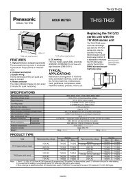
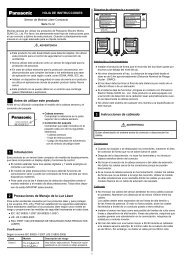
FEATURES<br />
1. 2.5 mm wide slim two-piece type<br />
connector<br />
Compact and slim body contributes to<br />
overall miniaturization of product design.<br />
<br />
• Width: 30% down<br />
• Footprint: 30% down<br />
1.0<br />
0.8<br />
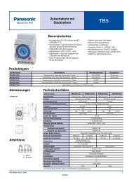
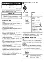
2. “ ”<br />
ensures high resistance to various<br />
environments in lieu of slim and low<br />
profile body<br />
Ni barrier<br />
construction<br />
(Against solder rise!)<br />
A4S<br />
2.5<br />
F4S<br />
3.6<br />
Bellows contact<br />
construction<br />
(Against dropping!)<br />
3. Mated heights of 0.8 and 1.0 mm are<br />
available for the same foot pattern.<br />
4. Connectors for inspection available<br />
APPLICATIONS<br />
Recommended for board-to-FPC<br />
connections of mobile equipment,<br />
such as cellular phones, smart<br />
phones, laptops and portable music<br />
players<br />
Porosity treatment<br />
(Against corrosive gases!)<br />
V notch and Double contact constructions<br />
(Against foreign particles and flux!)<br />
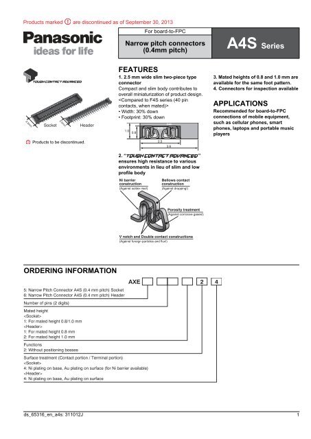
ORDERING INFORMATION<br />
5: Narrow Pitch Connector A4S (0.4 mm pitch) Socket<br />
6: Narrow Pitch Connector A4S (0.4 mm pitch) Header<br />
Number of pins (2 digits)<br />
Mated height<br />
<br />
1: For mated height 0.8/1.0 mm<br />
<br />
1: For mated height 0.8 mm<br />
2: For mated height 1.0 mm<br />
Functions<br />
2: Without positioning bosses<br />
Surface treatment (Contact portion / Terminal portion)<br />
<br />
4: Ni plating on base, Au plating on surface (for Ni barrier available)<br />
<br />
4: Ni plating on base, Au plating on surface<br />
AXE 2 4<br />
ds_65316_en_a4s: 311012J<br />
1
AXE5, 6 Products marked are discontinued as of September 30, 2013<br />
PRODUCT TYPES<br />
Mated height<br />
0.8mm<br />
1.0mm<br />
Number of pins<br />
Notes: 1. Order unit:<br />
For mass production: in 1-inner carton (1-reel) units<br />
Samples for mounting check: in 50-connector units. Please contact our sales office.<br />
Samples: Small lot orders are possible. Please contact our sales office.<br />
2. Please contact us for connectors having a number of pins other than those listed above.<br />
Part number<br />
Packing<br />
Socket Header Inner carton (1-reel) Outer carton<br />
10 AXE510124 AXE610124<br />
12 AXE512124 AXE612124<br />
14 AXE514124 AXE614124<br />
16 AXE516124 AXE616124<br />
18 AXE518124 AXE618124<br />
20 AXE520124 AXE620124<br />
22 AXE522124 AXE622124<br />
24 AXE524124 AXE624124<br />
26 AXE526124 AXE626124<br />
28 AXE528124 AXE628124<br />
30 AXE530124 AXE630124<br />
32 AXE532124 AXE632124<br />
34 AXE534124 AXE634124<br />
36 AXE536124 AXE636124<br />
38 AXE538124 AXE638124<br />
40 AXE540124 AXE640124<br />
44 AXE544124 AXE644124<br />
50 AXE550124 AXE650124<br />
54 AXE554124 AXE654124<br />
56 AXE556124 AXE656124<br />
60 AXE560124 AXE660124<br />
64 AXE564124 AXE664124<br />
70 AXE570124 AXE670124<br />
80 AXE580124 AXE680124<br />
10 AXE510124 AXE610224<br />
12 AXE512124 AXE612224<br />
14 AXE514124 AXE614224<br />
20 AXE520124 AXE620224<br />
24 AXE524124 AXE624224<br />
26 AXE526124 AXE626224<br />
30 AXE530124 AXE630224<br />
32 AXE532124 AXE632224<br />
40 AXE540124 AXE640224<br />
44 AXE544124 AXE644224<br />
50 AXE550124 AXE650224<br />
54 AXE554124 AXE654224<br />
60 AXE560124 AXE660224<br />
70 AXE570124 AXE670224<br />
80 AXE580124 AXE680224<br />
5,000 pieces 10,000 pieces<br />
2 ds_65316_en_a4s: 311012J
Products marked are discontinued as of September 30, 2013<br />
SPECIFICATIONS<br />
■ Characteristics<br />
<strong>Electric</strong>al<br />
characteristics<br />
Mechanical<br />
characteristics<br />
Environmental<br />
characteristics<br />
Lifetime<br />
characteristics<br />
Unit weight<br />
Item Specifications Conditions<br />
Rated current<br />
0.3A/pin contact (Max. 5 A at total pin contacts)<br />
Rated voltage<br />
60V AC/DC<br />
■ Material and surface treatment<br />
Part name Material Surface treatment<br />
Molded<br />
portion<br />
Contact and<br />
Post<br />
AXE5,6<br />
Breakdown voltage<br />
150V AC for 1 min.<br />
No short-circuiting or damage at a detection current of 1 mA<br />
when the specified voltage is applied for one minute.<br />
Insulation resistance Min. 1,000M (initial) Using 250V DC megger (applied for 1 min.)<br />
Contact resistance<br />
Composite insertion force<br />
Composite removal force<br />
Contact holding force<br />
(Socket contact)<br />
Max. 90m<br />
Max. 1.200N/pin contacts pin contacts (initial)<br />
Min. 0.165N/pin contacts pin contacts<br />
Min. 0.20N/pin contacts<br />
Based on the contact resistance measurement method<br />
specified by JIS C 5402.<br />
Measuring the maximum force.<br />
As the contact is axially pull out.<br />
Ambient temperature –55C to +85C No freezing at low temperatures. No dew condensation.<br />
Soldering heat resistance<br />
Storage temperature<br />
Thermal shock resistance<br />
(header and socket mated)<br />
Humidity resistance<br />
(header and socket mated)<br />
Saltwater spray resistance<br />
(header and socket mated)<br />
H2S resistance<br />
(header and socket mated)<br />
Insertion and removal life<br />
LCP resin<br />
(UL94V-0)<br />
Copper alloy<br />
—<br />
Peak temperature: 260C or less (on the surface of<br />
the PC board around the connector terminals)<br />
300C within 5 sec. 350C within 3 sec.<br />
–55C to +85C (product only)<br />
–40C to +50C (emboss packing)<br />
5 cycles,<br />
insulation resistance min. 100M,<br />
contact resistance max. 90m<br />
120 hours,<br />
insulation resistance min. 100M,<br />
contact resistance max. 90m<br />
24 hours,<br />
insulation resistance min. 100M,<br />
contact resistance max. 90m<br />
48 hours,<br />
contact resistance max. 90m<br />
30 times<br />
20 pin contact type: Socket: 0.02 g Header: 0.01 g<br />
Infrared reflow soldering<br />
Soldering iron<br />
No freezing at low temperatures. No dew condensation.<br />
Conformed to MIL-STD-202F, method 107G<br />
Order Temperature (°C) Time (minutes)<br />
0<br />
1 –55−3 30<br />
2<br />
Max. 5<br />
+3<br />
3<br />
85 0 30<br />
4<br />
Max. 5<br />
0<br />
–55 −3<br />
Bath temperature 402C,<br />
humidity 90 to 95% R.H.<br />
Bath temperature 352C,<br />
saltwater concentration 51%<br />
Bath temperature 402C, gas concentration 31 ppm,<br />
humidity 75 to 80% R.H.<br />
Repeated insertion and removal speed of max. 200 times/<br />
hours<br />
Contact portion: Base: Ni plating Surface: Au plating<br />
Terminal portion: Base: Ni plating Surface: Au plating (except the terminal tips)<br />
The socket terminals close to the portion to be soldered have nickel barriers (exposed nickel portions).<br />
Soldering terminals: Sockets: Base: Ni plating Surface: Pd+Au flash plating (except the terminal tips)<br />
Headers: Base: Ni plating Surface: Au plating (except the terminal tips)<br />
ds_65316_en_a4s: 311012J<br />
3
AXE5, 6 Products marked are discontinued as of September 30, 2013<br />
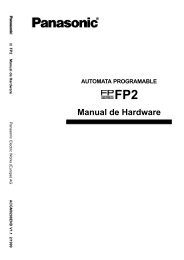
DIMENSIONS<br />
Interested in CAD <strong>data</strong>? You can obtain CAD <strong>data</strong> for all products with a<br />
mark from your local <strong>Panasonic</strong> <strong>Electric</strong> <strong>Works</strong> representative.<br />
CAD Data<br />
■ Socket (Mated height: 0.8 mm/1.0 mm)<br />
Dimension table (mm)<br />
(Unit: mm)<br />
0.70 (Suction face)<br />
A<br />
B±0.1<br />
0.40±0.05<br />
0.15±0.03<br />
0.77<br />
Terminal coplanarity<br />
0.08<br />
(Contact and<br />
soldering terminals)<br />
Number of contacts/<br />
dimension<br />
A B C<br />
10 4.5 1.6 3.4<br />
12 4.9 2.0 3.8<br />
14 5.3 2.4 4.2<br />
16 5.7 2.8 4.6<br />
2.20<br />
1.72<br />
2.50<br />
18 6.1 3.2 5.0<br />
(0.39)<br />
20 6.5 3.6 5.4<br />
22 6.9 4.0 5.8<br />
24 7.3 4.4 6.2<br />
26 7.7 4.8 6.6<br />
Y note<br />
(0.90)<br />
28 8.1 5.2 7.0<br />
30 8.5 5.6 7.4<br />
32 8.9 6.0 7.8<br />
2.50<br />
34 9.3 6.4 8.2<br />
Z note<br />
0.30±0.03<br />
C±0.1<br />
1.06<br />
36 9.7 6.8 8.6<br />
38 10.1 7.2 9.0<br />
40 10.5 7.6 9.4<br />
General tolerance: 0.2<br />
44 11.3 8.4 10.2<br />
50 12.5 9.6 11.4<br />
54 13.3 10.4 12.2<br />
Note: Since the soldering terminals has a single-piece construction,<br />
sections Y and Z are electrically connected.<br />
56 13.7 10.8 12.6<br />
60 14.5 11.6 13.4<br />
64 15.3 12.4 14.2<br />
70 16.5 13.6 15.4<br />
80 18.5 15.6 17.4<br />
■ Header (Mated height: 0.8 mm)<br />
Dimension table (mm)<br />
0.70 (Suction face)<br />
A<br />
B±0.1<br />
0.40±0.05<br />
0.15±0.03<br />
1.42<br />
0.65<br />
Terminal coplanarity<br />
0.08<br />
(Post and<br />
soldering terminals)<br />
2.00<br />
Number of contacts/<br />
dimension<br />
A B C<br />
10 3.8 1.6 3.2<br />
12 4.2 2.0 3.6<br />
14 4.6 2.4 4.0<br />
16 5.0 2.8 4.4<br />
18 5.4 3.2 4.8<br />
(0.36)<br />
1.28<br />
20 5.8 3.6 5.2<br />
22 6.2 4.0 5.6<br />
24 6.6 4.4 6.0<br />
26 7.0 4.8 6.4<br />
Soldering terminals<br />
0.15±0.03<br />
C±0.1<br />
(0.31)<br />
0.84<br />
1.46<br />
Soldering terminals<br />
28 7.4 5.2 6.8<br />
30 7.8 5.6 7.2<br />
32 8.2 6.0 7.6<br />
34 8.6 6.4 8.0<br />
36 9.0 6.8 8.4<br />
38 9.4 7.2 8.8<br />
40 9.8 7.6 9.2<br />
General tolerance: 0.2<br />
44 10.6 8.4 10.0<br />
50 11.8 9.6 11.2<br />
54 12.6 10.4 12.0<br />
56 13.0 10.8 12.4<br />
60 13.8 11.6 13.2<br />
64 14.6 12.4 14.0<br />
70 15.8 13.6 15.2<br />
80 17.8 15.6 17.2<br />
4 ds_65316_en_a4s: 311012J
Products marked are discontinued as of September 30, 2013<br />
■ Header (Mated height: 1.0 mm)<br />
AXE5,6<br />
0.70 (Suction face)<br />
Soldering terminals<br />
A<br />
B±0.1<br />
0.40±0.05<br />
0.15±0.03<br />
0.15±0.03<br />
C±0.1<br />
1.42<br />
(0.31)<br />
0.84<br />
1.46<br />
Soldering terminals<br />
0.85<br />
(0.36)<br />
Terminal coplanarity<br />
0.08<br />
(Post and<br />
soldering terminals)<br />
1.28<br />
2.00<br />
General tolerance: 0.2<br />
Dimension table (mm)<br />
Number of pins/<br />
dimension<br />
A B C<br />
10 3.8 1.6 3.2<br />
12 4.2 2.0 3.6<br />
14 4.6 2.4 4.0<br />
20 5.8 3.6 5.2<br />
24 6.6 4.4 6.0<br />
26 7.0 4.8 6.4<br />
30 7.8 5.6 7.2<br />
32 8.2 6.0 7.6<br />
40 9.8 7.6 9.2<br />
44 10.6 8.4 10.0<br />
50 11.8 9.6 11.2<br />
54 12.6 10.4 12.0<br />
60 13.8 11.6 13.2<br />
70 15.8 13.6 15.2<br />
80 17.8 15.6 17.2<br />
■ Socket and Header are mated<br />
Header<br />
0.80±0.1<br />
Header<br />
1.00±0.1<br />
Socket<br />
Socket<br />
EMBOSSED TAPE DIMENSIONS (Unit: mm) (Common for respective contact types, sockets and headers)<br />
■ Specifications for taping<br />
(In accordance with JIS C 0806-1990. However, not applied to<br />
the mounting-hole pitch of some connectors.)<br />
■ Specifications for the plastic reel<br />
(In accordance with EIAJ ET-7200B.)<br />
Leading direction after packaging<br />
Tape I<br />
(A±0.3)<br />
(C)<br />
(1.75)<br />
8.0 (2.0) (4.0)<br />
+0.1<br />
1.5 0 dia.<br />
Tape II<br />
(A±0.3)<br />
(B)<br />
(C)<br />
(1.75)<br />
8.0 (2.0) (4.0)<br />
+0.1<br />
1.5 0 dia.<br />
380 dia.<br />
(D±1)<br />
Top cover tape<br />
Embossed carrier tape<br />
Embossed mounting-hole<br />
Taping reel<br />
■ Dimension table (Unit: mm)<br />
Type/Mated height Number of pins Type of taping A B C D Quantity per reel<br />
Common for sockets<br />
and headers<br />
0.8 mm/1.0 mm<br />
Max. 24 Tape I 16.0 — 7.5 17.4 5,000<br />
26 to 70 Tape I 24.0 — 11.5 25.4 5,000<br />
80 Tape II 32.0 28.4 14.2 33.4 5,000<br />
■ Connector orientation with respect to embossed tape feeding direction<br />
Direction<br />
of tape progress<br />
Type<br />
Socket<br />
Common for A4S<br />
Header<br />
Note: There is no indication on this product regarding top-bottom or left-right orientation.<br />
ds_65316_en_a4s: 311012J<br />
5
AXE5, Products marked 6 are discontinued as of September Products 30, 2013marked are discontinued as of September 30, 2013<br />
For board-to-FPC<br />
Connectors for<br />
inspection usage<br />
(0.4mm pitch)<br />
A4S Series<br />
2.5mm<br />
2.0mm<br />
Socket<br />
Header<br />
Products to be discontinued.<br />
FEATURES<br />
1. 3,000 mating and unmating cycles<br />
2. Same external dimensions and foot<br />
patterns as standard type.<br />
3. Improved mating<br />
Insertion and removal easy due to a<br />
reduction in mating retention force. This<br />
is made possible by a simple locking<br />
structure design.<br />
Note: Mating retention force cannot be<br />
warranted.<br />
APPLICATIONS<br />
Ideal for module unit inspection and<br />
equipment assembly inspection<br />
TABLE OF PRODUCT TYPES<br />
✩: Available for sale<br />
Product name<br />
Number of pins<br />
A4S<br />
for inspection 10 12 14 16 18 20 22 24 26 28 30 32 34 36 38 40 44 50 54 56 60 64 70 80<br />
✩ ✩ ✩ ✩ ✩ ✩ ✩ ✩ ✩ ✩ ✩ ✩ ✩ ✩ ✩ ✩ ✩ ✩ ✩ ✩ ✩ ✩ ✩ ✩<br />
Notes: 1. Please inquire about numbers of pins other than those given above.<br />
2. Please inquire with us regarding availability.<br />
3. Please keep the minimum order quantities no less than 50 pieces per lot.<br />
4. Please inquire if further information is needed.<br />
PRODUCT TYPES<br />
Specifications Part No. Specifications Part No.<br />
Socket Without positioning bosses AXE5E26 Header Without positioning bosses AXE6E26<br />
Note: When placing an order, substitute the “” (asterisk) in the above part number with the number of pins for the specific connector.<br />
NOTES<br />
■ Recommended PC board and metal<br />
mask patterns<br />
Connectors are mounted with high pitch<br />
density, intervals of 0.35 mm, 0.4 mm or<br />
0.5 mm.<br />
In order to reduce solder bridges and<br />
other issues make sure the proper levels<br />
of solder is used.<br />
The figures to the right are recommended<br />
metal mask patterns. Please use them as<br />
a reference.<br />
• Socket (Mated height: 0.8mm/1.0mm)<br />
Recommended PC board pattern (TOP VIEW)<br />
2.90±0.03<br />
1.06±0.03<br />
(0.92)<br />
0.40±0.03<br />
0.23±0.03<br />
0.90±0.03<br />
1.45±0.03<br />
(0.50)<br />
0.20±0.03<br />
1.90±0.03<br />
C 0.30<br />
: Insulation area<br />
Recommended metal mask opening pattern<br />
Metal mask thickness: When 120m<br />
(Terminal opening ratio: 70%)<br />
(Metal-part opening ratio: 100%)<br />
2.90±0.01<br />
1.06±0.01<br />
(0.92)<br />
0.40±0.01<br />
0.20±0.01<br />
(0.40)<br />
2.00±0.01<br />
2.80±0.01<br />
• Header (Mated height: 0.8mm/1.0mm)<br />
Recommended PC board pattern (TOP VIEW)<br />
1.66±0.03<br />
0.60±0.03<br />
(0.53)<br />
0.40±0.03<br />
0.23±0.03<br />
0.45±0.03<br />
0.80±0.03<br />
Recommended metal mask opening pattern<br />
Metal mask thickness: When 120m<br />
(Terminal opening ratio: 70%)<br />
(Metal-part opening ratio: 100%)<br />
1.66±0.01<br />
0.60±0.01<br />
(0.53)<br />
0.40±0.01<br />
0.20±0.01<br />
(0.65)<br />
1.10±0.03<br />
2.40±0.03<br />
(0.52)<br />
1.26±0.01<br />
2.30±0.01<br />
0.90±0.01<br />
1.45±0.01<br />
C 0.30<br />
0.45±0.01<br />
0.80±0.01<br />
For Cautions for Use, see the “GENERAL NOTES ON USING ADVANCED SERIES<br />
NARROW-PITCH CONNECTORS” of the Connector Technical Information. For<br />
other details, please verify with the product specification <strong>sheet</strong>s.<br />
6 ds_65316_en_a4s: 311012J